

Abstract
DNA has become the biomolecule of choice for molecular computation that may one day complement conventional silicon-based processors. In general, DNA computation is done in individual tubes, is slow in generating chemical outputs in response to chemical inputs, and requires fluorescence readout. Here, we introduce a new paradigm for DNA computation where the chemical input is processed and transduced into a mechanical output using dynamic DNA-based motors operating far-from-equilibrium. We show that DNA-based motors with onboard logic (DMOLs) can perform Boolean functions (NOT, YES, AND, and OR) with 15 min readout times. Since DMOLs are micron-sized, massive arrays of DMOLs that are identical or uniquely encoded by size and refractive index can be multiplexed and perform motor-to-motor communication on the same chip. Finally, DMOL computational outputs can be detected using a conventional smartphone camera, thus transducing chemical information into the electronic domain in a facile manner suggesting potential applications.
One of the hallmarks of living systems is the ability to autonomously detect chemical inputs and process this chemical information to execute sophisticated functions such as locomotion.1 For example, E. coli switches the rotation of its flagella in response to nutrient concentrations. Creating synthetic systems that recapitulate the sense/process/respond capability of living systems is desirable as it would represent an important step toward next generation sensors, computational devices, and molecular robotics.
The most promising synthetic systems that demonstrate aspects of sensing, computation, and actuation at the molecular scale rely on engineering nucleic acids. This is because of the highly predictable kinetics and thermodynamics of Watson-Crick-Franklin base pairing and availability of triggered reactions such as toehold-mediated strand displacement (TMSD)2,3,4,5 and the hybridization chain reaction.6,7,8,9 In particular, the TMSD reaction has been used in building dynamic DNA nanostructures that process molecular inputs and produce specific responses.10,4,11,12,13 For example, Seelig et al. demonstrated that nucleic acid TMSD logic gates can sense, process, and release output oligonucleotides to generate a fluorescence signal.14 Qian and Winfree later applied the TMSD reaction to create a nucleic acid “robot” that undertakes a 2D random walk to sort DNA.15 More recently, Cherry and Qian used TMSD circuitry to create a “winner-takes-all” neural network that exhibits autonomous behavior.16 In all these examples, the logic gates use binary-encoded molecules as input (present=1, absent=0) and optical/electrochemical signals as output (high=1, low=0).14,17,18,19,20 To date, the primary output of DNA computing systems is fluorescence.21,22,23,24,25 Less common detection methods include single molecule readouts, such as TEM and AFM, to detect nanostructure translocation along a scaffold.26,27,28 Transducing the output of DNA computation into microscopic or macroscopic responses that parallel the input-triggered locomotion of living systems may become useful for real-world applications.
Herein, we address this challenge by engineering DNA-based motors with “onboard” logic (DMOLs) that transduce chemical information into mechanical output in the form of macroscopic locomotion. DMOLs take advantage of rolling DNA-based motors that move at ~μm/minute speeds with high endurance (up to ~mm).29,30 Motors are comprised of a single stranded DNA-coated (ssDNA) particle that hybridizes to complementary RNA immobilized on a planar chip (Fig. 1). Motors move upon addition of RNaseH as it selectively hydrolyzes RNA duplexed with DNA but is inactive against ssRNA. Thus, DNA-RNA hybridization at the motor-chip junction leads to rapid degradation of the RNA which creates a chemical gradient of RNA. The free energy of RNA-DNA hybridization down this gradient drives motion. Rolling motors are not switches and do not move by random diffusion, rather these are bona fide motors. Most reported DNA motors are not formally processive machines. Rather, these are often switches that toggle between two states and hence are unable to generate useful work such as motion.31,32
Fig. 1 |. Schematic of DNA-based motors with onboard logic (DMOLs) detecting the presence of a chemical input.
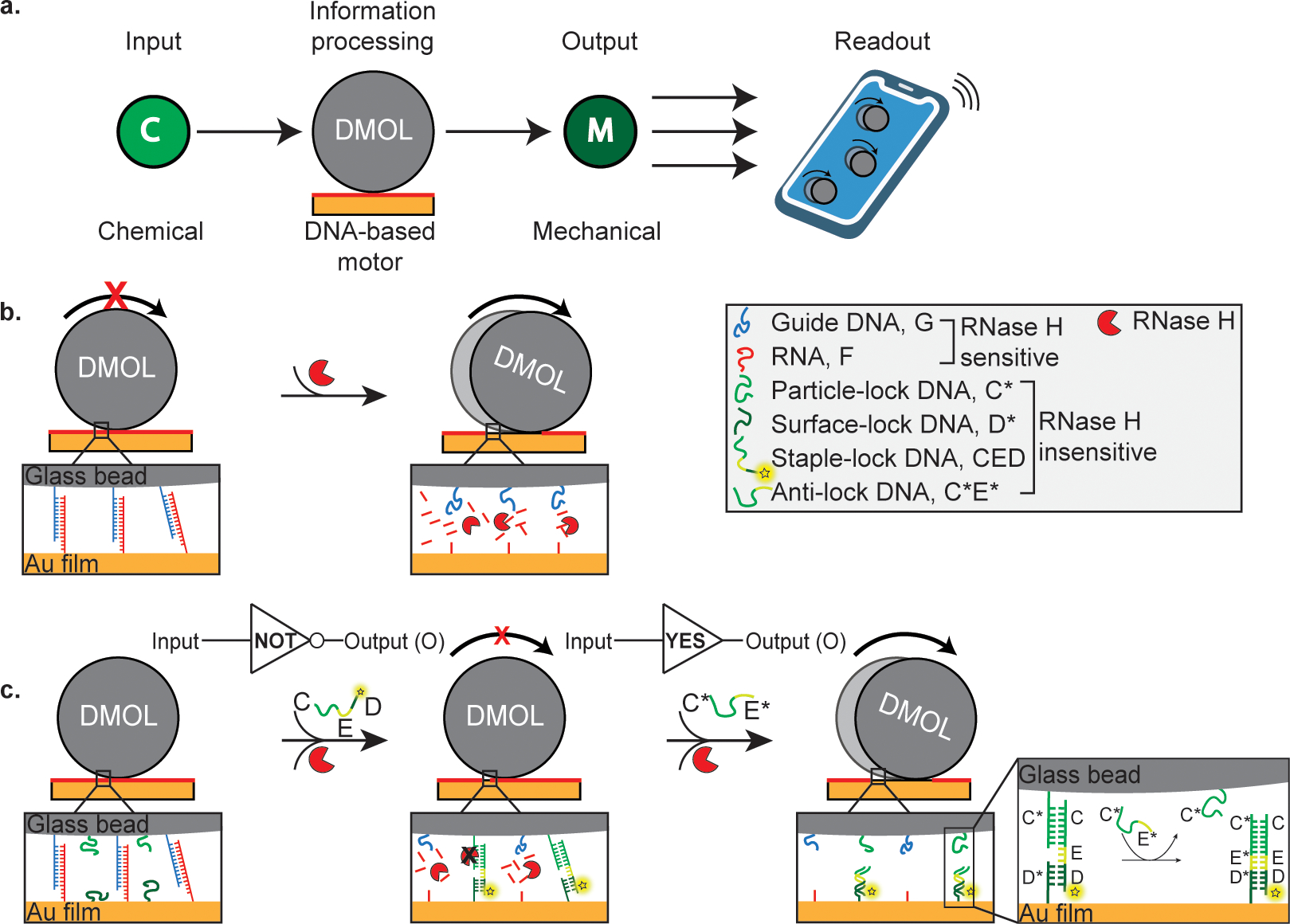
a, Illustration of information processing DMOLs sensing chemical input and transducing mechanical output which can be detected via smartphone readout. b, DMOLs modified with guide DNA (G) hybridize to complementary RNA (F) presented on the chip. The motors remain stationary until the addition of ribonuclease H (RNase H). In the presence of RNase H, RNA is selectively cleaved, and the motors roll forward through a burnt bridge mechanism. c, In addition to G, the DMOLs are functionalized with particle-lock DNA (C*). The chip is modified with a binary mixture of surface-lock (D*) and F. Two different types of duplexed strands form with the addition of the staple-lock DNA strands (CED): 1) G hybridizes with complementary F (degraded by RNase H) and 2) CED hybridizes with C* on the particle and the surface bound D* (RNase H resistant). In the presence of RNase H the particle remains stalled on the surface as it is mechanically locked by the DNA-DNA duplex formed (C*:CED:D*). The DMOLs serve as a NOT gate with the presence of CED stalling motion and the absence resulting in motion. An anti-lock DNA strand (C*E*) displaces CED from the particle through the toehold-mediated strand displacement (TMSD) reaction and engages motor motion. Acting as a YES gate, only the presence of an anti-lock DNA strand will result in motor motion.
DMOLs speed is highly sensitive to kcat, kon, and koff rates of RNA/DNA hydrolysis, hybridization, and dissociation, respectively, and therefore microscopic motion is a readout of molecular input signals. In this work, we first demonstrate the ability to stall motion using rationally designed nucleic acids. Next, we use TMSD reactions to engineer Boolean logic operations into motors including DMOLs with NOT, YES, AND, and OR gates. Because DMOLs produce motion rather than color or fluorescence as the output, multiple unique DMOLs with different logic operations can be mixed on the same chip to process information in a parallelized manner. Multiplexed DMOLs were barcoded by fluorescence tagging, or by using motors with specific particle size and refractive index (RI). DMOL size and RI can be detected using conventional brightfield microscopy, which is advantageous as this type of encoding potentially offers massive parallelization of information processing. Through cascading of simple logic gates, we show communication between different DMOLs performing independent logic operations on the same chip. Finally, we demonstrate the accessibility of multiplexed DMOLs by processing five unique inputs using a smartphone camera. Given that DMOL outputs trigger rapid mechanical work in the form of microscopic motion, readout was performed in as little as 15 min, providing a facile method for DNA computation.
Design of DNA-based motors with onboard logic (DMOLs)
We programmed the motors to develop stop-and-go motion in response to an external oligonucleotide input by conditioning motion to a TMSD reaction (Fig. 1). The particles were functionalized with the ssDNA guide (G) which binds to complementary ssRNA fuel (F) on the chip surface (Supplementary Table 1 and Supplementary Fig. 1). The motor and chip surface were also modified with ssDNA that can form stable lock complexes to stall the motors. The “onboard logic” requires oligonucleotide components that must be surface anchored to generate 100+ pN resistive forces that lead to stalling.33 Therefore, the lock complex was comprised of ssDNA on the motor (C*), ssDNA on the chip (D*), and a complementary strand that binds to both C* and D* with an internal unbound 10 nt toehold domain E (strand CED) as shown in Fig. 1c. The lock complex is insensitive to RNAseH hydrolysis and hence stalls motion in situ as it assembles at the junction between the motor and the chip surface. We hypothesized that displaying C*:CED on the motor along with complementary D* on the chip surface would lead to stalling (Fig. 1c). In this case, translocation requires mechanical shearing of multiple lock complexes which exceeds the 100+ pN force generation capacity of these motors.33 Because motion is ultrasensitive to the binding events at the motor-chip junction, the motor responds in a manner that is effectively binary to the lock complex, which lends itself to using motion as a digital output Boolean response; motion=1 and stalling=0. In Fig. 1c, for example, the motor behaves as a NOT gate where the presence of the CED (input=1) abrogates motion and output=0. Conversely, absence of CED (input=0) rescues motion (output = 1). Note that the starting state of all motors described in this work is a NOT gate.
In principle, displacement of the CED from the motor surface prevents formation of the lock complexes and rescues motion. In Fig. 1c, the presence of an anti-lock DNA (C*E*), input=1, leads to motion, output=1. The converse is true and absence of C*E*, input = 0, leads to stalling, output = 0. This type of Boolean operation is a YES gate (buffer gate), and CED release is driven by C*E* binding (Fig. 1c) because of the net gain in 10 base pairs in the toehold domain.2
To test the NOT/YES gate described above, we modified gold films with a binary mixture of two oligonucleotides, F and D* (Supplementary Fig.1). The total oligonucleotide density on the chip surface was ~50,000 molecules/μm2, and in initial experiments we introduced 1% D* and 99% F. Note that the F was Cy3-tagged to map RNA hydrolysis using fluorescence microscopy. The motors (5 μm silica particles) were modified with 90% G and 10% CED at an overall DNA density of ∼91,000 molecules/μm2 (ref33) (Supplementary Fig. 2). To visualize and quantify TMSD, CED was tagged with Cy5. We call these particles DMOL1 in subsequent discussion. With the addition of CED, DMOL1 was first immobilized on the chip surface due to D*-D and G-F hybridization. Addition of RNaseH led to a small but detectable motion (Fig. 2a). Despite the small translocation distances, we still observed consumption of Cy3-tagged F in the wake of the moving motors. CED-Cy5 oligo colocalized with the motors, confirming that the CED staple-lock remained bound during this experiment (Fig. 2a). Increasing the observation time to t=1 hr after RNaseH addition did not increase displacement significantly as the locked particles showed 2.9 ± 2.3 μm (n=100 particles) motion (Fig. 2b). Furthermore, DMOLs lacking the staple-lock DNA continued rolling on the surface with high displacements even at t=5 hr after RNaseH addition (Supplementary Fig. 3). This confirms that the CED lock complex irreversibly stalls motion through specific DNA-DNA hybridization.
Fig. 2 |. Computation of NOT and YES gates.

a, Representative fluorescence images along with overlay (at t = 30 minutes after RNase H addition) show Cy3-tagged RNA as well as the Cy5 fluorescently tagged DMOLs before the addition of anti-lock DNA (top) and after (bottom). b, The plot on the left shows the track lengths for DMOLs modified with 10% staple-lock DNA and added to the chip with 1% surface-lock. Track lengths are quantified 30 minutes and 60 minutes before the addition of anti-lock (−) as well as 30 minutes after (+). Similarly, the plot on the right shows the track lengths for the condition with 50% staple-lock and 5% surface-lock DNA. In both DMOL designs, track lengths increase in the presence of anti-lock. c, Plot of fluorescence intensity of the DMOLs (10% staple-lock, 1% surface-lock DNA) 30 minutes and 60 minutes before adding the anti-lock (−) and 30 minutes after (+). d, The plot on the left is the ratio of the mean track lengths with the anti-lock DNA (+) and without (−) with varying density of staple-lock and the surface-lock. The plot on the right is the ratio of the mean Cy5 fluorescence intensity with the anti-lock DNA (+) and without (−). e, Scheme of reversible YES/NOT gate operations showing 1 μm of anti-lock DNA (C*E*D*I*) rescuing motion and the staple-lock DNA (CEDI) stalling motion. f, Representative fluorescence images along with overlay (at t = 30 min after RNase H addition) show Cy3-tagged RNA as well as the FAM-staple-lock channel after the addition of staple-lock DNA (top) and anti-lock DNA (bottom). g, Ensemble DMOL trajectories (n> 100 DMOLs) plotted from the center (0,0) for two cycles of YES/NOT gate computation on the same chip. Color indicates time from 0–30 mins. h, The plot on the left shows the net displacements from brightfield particle tracking in presence of staple-lock/anti-lock DNA for both cycles. The plot on the right shows the corresponding FAM fluorescence intensity of the DMOLs. Green region represents DMOLs with output=1 and red with output=0. Error bars correspond to the standard deviation of n> 100 DMOLs from three independent experiments. ns,**,**** indicate not statistically significant, p=0.0013, and p<0.0001.
We next tested whether input C*E* can rescue DMOL1 motion. Here we used 1 μM C*E* for 1 hr prior to initiating motion with RNaseH (Supplementary Fig. 4). We observed a significant increase in the track length accompanied by a decrease in motor Cy5 intensity, confirming computation of the YES gate through TMSD-gated motion (Fig. 2a and Supplementary movie 1). Using the Cy3 depletion tracks from n > 100 motors, we found that the motor displacement increased from 2.3 ± 2.3 μm to 14.4 ± 7.6 μm at t=30 min after addition of C*E* (Fig. 2b). Similarly, motors lacking CED displayed track lengths of 11.5 ± 6.2 μm at t=30 min (Supplementary Fig. 5a). Plots of motor Cy5 intensity show that TMSD displaces >90% of the staple-lock strand (Fig. 2c). Brightfield particle tracking confirmed that anti-lock C*E* rescued motion and increased motor speed up to 2 μm/min from 0.25 μm/min (Supplementary Fig. 5b).
To further enhance the fidelity of the DMOL response we screened staple-lock and surface-lock DNA densities, as initial conditions with 10% staple-lock CED and 1% surface-lock D* showed incomplete stalling of DMOL1. We hypothesized that if we increase D* and CED density, or if we increase their rupture force, we could more effectively stall the motor while providing sufficient fuel RNA density and polyvalency to maintain processive and rapid motion. Our previous work showed that 3 or more 15mer DNA locks in a shearing geometry are required for stalling.33 Thus, the mechanical stability and density of the locks are important determinants of the S/N of our system. We explored four DMOL1 staple-lock/surface-lock densities: a) 10% staple-lock/1% surface-lock; b) 10% staple-lock/5% surface-lock; c) 50% staple-lock/1% surface-lock; and d) 50% staple-lock/5% surface-lock. Note that lock densities >50% led to motor dissociation (data not shown) and bounded the parameter space tested. We measured both track length and fluorescence intensity of the Cy5-labeled DMOLs with and without addition of anti-lock DNA (Fig. 2d, Supplementary Figs. 5c, 5d). To compare DMOL performance, we inferred the S/N of the logic gates based on the ratio of the track length with anti-lock normalized by the track length of motors lacking anti-lock. DMOLs were also compared based on the Cy5 intensity +/− anti-lock (Fig. 2d). DMOLs with 50% staple-lock/5% surface-lock showed the greatest S/N (Fig. 2d). This was mostly due to suppression of motion in the absence of anti-lock which was 0.4 ± 0.2 μm (Fig. 2b). Analysis of particle speed using brightfield videos confirmed this conclusion (Supplementary Fig. 5b). Taken together, we selected the 50% staple-lock and 5% surface-lock DMOL design for subsequent experiments as these motors displayed greater fidelity.
To test the reversibility of Boolean operations, we modified the staple-lock DNA on DMOL1 to include a 10nt terminal toehold. As illustrated in Fig. 2e, the FAM-tagged staple-lock DNA stalls DMOL1 while the anti-lock DNA rescues motion of DMOL1 on the same chip. Fluorescence microscopy confirmed that the staple-lock DNA stalls DMOL1 while the anti-lock DNA rescues motion (Fig. 2f and 2h). Ensemble particle tracking of n>100 DMOLs (taken at t=30 min) shows that we stalled and recovered motion between NOT/YES gates in the two cycles (Fig. 2g and 2h). In principle, one can go through many more cycles as the TMSD is reversible.
Computation of AND gate
Next, we designed and demonstrated an AND-gated motor, DMOL2, using two different staple-lock DNA strands (CED and MND) (Fig. 3a). When DMOL2 senses the two inputs (input=1), it is unlocked resulting in locomotion (output=1). In this design, input A displaces lock CED-Cy5, while input B displaces lock MND-FAM (Fig. 3a). These labels verified the TMSD reaction, as input A and input B led to loss of Cy5 and FAM signal from DMOL2, respectively. When DMOL2 was added to a surface comprised of 5% D*, motors were stalled as shown in Fig. 3b. Addition of either input A or input B (1 μM) did not trigger any detectable tracks (Fig. 3b). Fluorescence images confirmed that input A and B were active in mediating TMSD (Fig. 3b). Only when both inputs A and B were added did DMOL2 display motion (Supplementary movie 2). The track lengths for DMOL2 receiving input A (0.8 ± 0.7 μm) did not significantly differ from the tracks formed with no input added (0.3 ± 0.2 μm), p-value =0.6 (Fig. 3c). Track lengths increased to 6.6 ± 2.2 μm with both inputs A and B. Input A led to a ~20-fold reduction in Cy5 intensity, while input B led to a ~10-fold decrease in FAM signal (Fig. 3d). These fluorescence levels for DMOL2 were not different from background, indicating near quantitative removal of lock strands CED and MND. Taken together, this data confirms that DMOLs can be programmed to compute an AND gate through chemical to mechanical transduction.
Fig. 3 |. Computation of AND gate.

a, Illustration of the AND gate resulting in particle motion as output (O=1) only when both inputs A and B are present. b, Representative Cy3, Cy5 and FAM fluorescence images along with the overlay (at t = 30 minutes after RNase H addition) of no input, input A, input B, and input A+B. Addition of input A+B leads to an increase Cy3 depletion track lengths and a decrease in Cy5 and FAM fluorescence. c, Measured track lengths (t=30 minutes) with no input, input A, and input A+B. The track lengths for the control, without any staple-lock present, are also shown. DMOLs remain stalled with the addition of only one input; however, they are released from the surface when inputs A+B are present with average track lengths measuring 6.6 ± 2.2 μm. Green region represents DMOLs with output=1 and red with output=0. d, The plots show the difference in fluorescence intensity of DMOLs after 30 minutes of no input, input A, and input A+B. A decrease in Cy5 fluorescence intensity is observed when input A is added as the locks functionalized with Cy5 are displaced from the particle. In a similar manner, a decrease in FAM fluorescence intensity is observed when input B is added as locks functionalized with FAM are displaced from the particle. Error bars correspond to the standard deviation of n> 100 DMOLs from three independent experiments. ns, *, **** indicate not statistically significant, p=0.018, and p<0.0001.
Computation of OR gate
The OR gate function was designed such that either of two chemical inputs (input=1) yields locomotion (output=1). The OR gate motor (DMOL3) was functionalized with 10% C* and 90% guide DNA, G. DMOL3 was introduced to a chip with 5% surface-lock DNA, D*. The rationale for using lower density of C* (particle-lock) compared to the AND/YES gates which had 50% C* is because one of the inputs in the OR gate required that C* was occupied by binding to CED, and at high densities of CED, motors showed low processivity. As shown in Fig. 4a, lock CED is displaced from the particle by input A, thus leading to decrease of particle Cy5 fluorescence. Conversely, lock CED can also be displaced from the chip surface through input C, which maintains the CED lock on the particle but terminates its bond to the chip anchored D*. As a result, the Cy5 fluorescence intensity of the particle remains the same with input C. As we expected, when no input was present, DMOL3 was stalled on the surface (Fig. 4b). The addition of either input A or input C rescued motion. For example, input A led to a ~10-fold increase in track length from 0.5 ± 0.4 μm (no input) to 4.7 ± 1.5 μm (Fig. 4c). Likewise, input C triggered motion with track lengths of 4.1 ± 1.0 μm. For comparison, DMOL3 motors lacking staple-lock CED displayed tracks of 4.1 ± 1.4 μm on a surface with 5% D*. Note the track lengths for these motors are shorter due to the smaller size of DMOL3 (3 μm).29 Confirming the TMSD reaction, input A led to a decrease in particle Cy5 fluorescence intensity as CED was displaced from the particle (Fig. 4d). Meanwhile, input C did not change the particle’s fluorescence intensity validating that the lock CED is displaced from the chip surface. Therefore, we show that with careful design of nucleic acid lock domains, DMOLs can be programmed with OR gate function in a facile manner.
Fig. 4 |. Computation of OR gate.

a, Illustration of the OR gate indicating particle motion as an output (O=1) with either input A or C present. b, Representative Cy3 and Cy5 fluorescence images along with the overlay (at t = 30 minutes after RNase H addition) of no input, input A, and input C. Depleted Cy3-RNA tracks are observed with either input A or C. c, Measured track lengths (t= 30 minutes) of no input, input A or input C. The track lengths for the control, without any staple-lock present, are also shown. The DMOLs resulted in motion with either the addition of input A (4.7 ± 1.5 μm) or input C (4.1 ± 1.0 μm). Green region represents DMOLs with output=1 and red with output=0. The plot on the right shows the difference in fluorescence intensity of the DMOLs after 30 minutes of no input, input A or input C. A decrease in Cy5 fluorescence intensity is observed when input A is added as the locks labeled with Cy5 are displaced from the DMOL. However, no decrease in DMOL Cy5 intensity was observed upon the addition of input C as the labeled locks are displaced from the surface but remain on the particle. Error bars correspond to the standard deviation of n> 100 DMOLs from three independent experiments. ns, **, **** indicates not statistically significant, p=0.0015, and p<0.0001.
Multiplexing fluorophore-encoded DMOLs
More sophisticated computations require multiple orthogonal logic gates to operate in tandem and in sequence. Some of the advantages of DMOLs include their small size and ease of programmability and thus there is the potential for carrying out multiple logical operations in a massively parallel fashion. To demonstrate parallel multiplexing where two independent DMOLs perform computation in the same pot, we aimed to integrate YES as well as AND-gated computing DMOLs on the same chip. As a proof-of-concept, DMOLs were encoded with unique fluorophores denoting their identities. The CED lock sequence of the YES-gated DMOL (DMOL1) was tagged with Cy5 while the AND-gated DMOL (DMOL2) was tagged with Cy5 and FAM dyes that were conjugated to CED and MND lock, respectively. Cy5-encoded DMOL1 will respond only to input A, while the FAM/Cy5-encoded DMOL2 will respond to both input A and B (Fig. 5a). DMOL1 and DMOL2 were prepared and added to a chip at a 1:1 stoichiometry. Upon addition of input A, DMOL1 tracks increased to 8.4 ± 4.9 μm in length (Fig. 5b) accompanied by Cy3-RNA depletion tracks and loss of Cy5 signal (Fig. 5c, Supplementary Fig. 6, and Supplementary movie 3). In contrast, DMOL2 remained stalled with input A (track lengths 0.3 ± 0.2 μm) and as expected Cy5 signal was diminished while FAM was maintained (Figs. 5b and c). We next added input B to the same chip for 60 min and then imaged to monitor motion. The Cy5 and FAM channels now showed a loss in signal for DMOL2 confirming lock displacement (Fig. 5c and Supplementary Fig. 6). DMOL2 tracks significantly increased upon addition of input B. Confirming the specificity of multiplexed detection, both DMOLs 1 and 2 stalled when they were introduced only to input B (Fig. 5b and c). DMOL2 only moved in the presence of both inputs A and B. Thus, this data demonstrates that DMOLs can be multiplexed and parallelized to detect unique chemical inputs in the same chip.
Fig. 5 |. Encoding DMOLs to multiplex and demonstrate communication.

a, Illustration depicting computation of YES gate by DMOL1 and AND gate by DMOL2. DMOL1 moves when input A is present while DMOL2 moves when A+B are present. b, The plots show the difference in track lengths of the DMOLs after the addition of input A, input B, and input A+B for the two different motors. DMOL1 is triggered with the addition of input A whereas DMOL2 only in the presence of input A+B. Green region represents DMOLs with output=1 and red with output=0. c, Representative Cy3, Cy5 and FAM fluorescence images along with the overlay (at t = 30 minutes after RNase H addition). Cy3-RNA depleted tracks are observed for DMOL1 in the presence of input A and input A+B. The addition of input A also leads to a decrease in Cy5 fluorescence intensity. No Cy3 depleted tracks are observed for DMOLs 1 or 2 in the presence of input B. The addition of input B leads to a decrease in FAM fluorescence intensity. Input A+B engages motion for DMOLs 1 and 2 as shown by the increase in Cy3 depleted tracks. d, Schematic of a two-layer cascading logic circuit. DMOL4 (YES-gate) was functionalized with 30% particle-lock, C* and 70% G. The particle lock density was reduced to 30% to accommodate the long length of the staple-lock oligo (83nt). DMOL5 (OR-gate) was functionalized with 10% particle-lock, M* and 90% G. e, The plot on the top shows the track lengths for DMOLs 4 and 5 with no input, input D, and input E. Both DMOL4 and 5 engage in motion with the addition of input D whereas input E results in motion only for DMOL5. Green region represents DMOLs with output=1 and red with output=0. The plot on the bottom represents the difference in fluorescence intensity of the DMOLs with no input, input D, and input E. A decrease in FAM fluorescence intensity for both DMOLs is observed when input D is added as the FAM-labeled locks are displaced from the DMOLs. Input E only leads to a decrease in fluorescence for DMOL5. Error bars correspond to the standard deviation of n> 100 DMOLs from three independent experiments. ns, *, **** indicate not statistically significant, p=0.018, and p<0.0001.
DMOL-to-DMOL networking through cascading logic gates
Now that we established the ability to encode different DMOLs on the same chip and given that each DMOL operates as an independent “agent”, we next aimed to design DMOLs that can communicate through cascading logic gates. We leverage the facile scalability and programmability of our architecture in designing a two-layer YES-OR cascade as illustrated in Fig. 5d and Supplementary Fig. 7. In this design, DMOL4 (5 μm silica sphere) is a YES-gate while DMOL5 (6 μm polystyrene sphere) is an OR-gate. Both DMOL4 and 5 were then incubated with their respective FAM-tagged staple-lock DNA and added to a chip with 10% surface-lock DNA. In the absence of input, both DMOLs had high FAM intensity and remained stalled (Fig. 5e and Supplementary Fig. 8a). When input D was added (input= 1, 10 μM), motion was observed in both DMOL4 and 5 and accompanied by a decrease in FAM signal confirming loss of staple-lock DNA (output=1). When DMOL5 alone was exposed to input D (1 μM), no motion was observed and FAM fluorescence remained the same indicating that DMOL5 is responding to the output from DMOL4 (Supplementary Fig. 8b). Input E (input=1, 1 μM) only triggered DMOL5 motion (output=1) but not DMOL4 motion (Fig. 5e and Supplementary Fig. 8a). Although not demonstrated here, the output of DMOL5 can then bind downstream another set of logic gates. Taken together, we have demonstrated communication between DMOLs by organizing the logic gates such that the output of one DMOL could serve as the input for another downstream DMOL.
Multiplexing with DMOLs by size and material
For molecular computing to one day complement the capabilities of traditional silicon-based computers, molecular systems need to be able to perform massive multiplexing of logic operations. Fluorophore-based encoding described above is limited to tens of unique multiplexing DMOLs because of the spectral bandwidth of unique fluorophores. Another challenge is that chemical-to-mechanical transduction is currently being read out using fluorescence in a high-end microscope which limits wide-spread adoption and portability. To address these issues, we sought alternate encoding and readout strategies. One approach is the use of DMOLs of different size and material which can be detected through simple brightfield imaging (Fig. 6a). We chose to barcode the DMOLs based on size ranging from 3 μm to 6 μm comprised of materials such as silica and polystyrene which are easily distinguishable using brightfield imaging (Supplementary Fig. 9). Moreover, the μm size of DMOLs and their μm displacements can be conveniently detected using a smartphone-based microscope. Fig. 6a shows a representative brightfield image of three different DMOLs obtained using a smartphone camera. We encoded the DMOLs as follows: DMOL2 (2-input AND-gate) was a 6 μm polystyrene bead, DMOL3 (OR-gate) was a 3 μm polystyrene bead, and DMOL6 (3-input AND-gate) was a 5 μm silica bead. To test multiplexing, DMOLs 2, 3, and 6 were prepared and added to a chip at a 1:1:1 stoichiometry. As depicted in Fig. 6b, DMOL2 responds to input A+B, DMOL3 to input A or C, and DMOL6 to input A+B+D. Readout required the acquisition of 15 min timelapse videos following addition of RNaseH. The trajectories of DMOL2, 3, and 6 were analyzed by particle tracking through brightfield imaging and are shown in Fig. 6c after the addition of each input. When input A was added, DMOL3 moved along the surface with a net displacement of 1.1 ± 0.7 μm (Fig. 6c, i and Supplementary movie 4). In contrast, DMOL2 and 6 remained stalled (0.1 ± 0.1 μm and 0.1 ± 0.2 μm, respectively). When input A+B were added, DMOL2 moved 2.6 ± 0.9 μm while DMOL6 remained stalled (0.2 ± 0.1 μm) (Fig. 6c, ii and Supplementary movie 5). Input A+B+C once again rescued motion of DMOL3 along with DMOL2 (Fig. 6c, iii and Supplementary movie 6). Input A+B+C+F triggered the motion of all DMOLs displaying net displacements of 2.3 ± 1.1 μm, 1.2 ± 0.7 μm and 1.2 ± 1.2 μm, for DMOL2, 3, and 6, respectively (Fig. 6c, iv and Supplementary movie 7). The Cy3-RNA depletion tracks formed by each DMOL are shown in Supplementary Fig. 10 along with the quantification of their track lengths and fluorescence intensities. This data shows that DMOLs with different logic operations can be mixed on the same chip to process information in a parallelized manner. Importantly, brightfield readout allows DMOLs to convert chemical information into the modern electronic domain directly.
Fig. 6 |. Size and material encoded DMOLs.

a, (Left) Setup of smartphone microscope and a representative BF image of DMOLs 2,3, and 6 with the trajectories shown for a 15 min timelapse acquisition. (Right) A plot of the different sizes and material of DMOL2 (6 μm silica particle), 3 (3 μm polystyrene particle), and 6 (5 μm polystyrene particle). b, Schematic illustrating computation of two-input AND gate by DMOL2, OR gate by DMOL3, and three-input AND gate by DMOL6. c i), Ensemble trajectories of different size and material encoded DMOLs as well as the corresponding net displacements 15 minutes after RNase H addition with input A, ii) input A+B, iii), input A+B+C, and iv) input A+B+C+F. Green region represents DMOLs with output=1 and red with output=0. Error bars correspond to the standard deviation of n> 20 DMOLs from three independent experiments. ns, **, **** indicates not statistically significant, p=0.0015, and p<0.0001.
Conclusions
In this paper we present a method of molecular computation using DNA-based motors. We showed that DMOLs can compute NOT, YES, AND, and OR gates. Processing can be performed in series or in parallel with multiple uniquely encoded DMOLs. Specifically, the DMOLs respond to two inputs in series; at first, they are locked producing no motion (NOT gate), but then a different input leads to motion (YES/AND/OR gate). Figures 5 and 6 show orthogonal motors operating in tandem. Processing agents operating in parallel and in series represent important components to build more complex computational systems. While we have not extensively tested how the fidelity of DMOL processing responds with readout time, we find that a 15 min time window provides multi-micron displacements and offers sufficient specificity for the proof-of-concept experiments shown here. In principle, longer readout times will enhance the fidelity of information processing ∝ 1/t1/2. Nonetheless, 15 min readouts compare favorably to the state-of-the-art35 and given that DMOLs operate in a parallel fashion, scaling additional operations will not require longer readout times.
We demonstrate two types of barcoding for multiplexed DMOLs using either fluorophore-encoding or by using particles of different size and material. The latter type of encoding may offer upwards of thousands of unique barcodes. As a conservative estimate, there are tens of different microparticle materials reported, and each of these can be synthesized with tens to hundreds of distinguishable sizes and shapes. Additional channels of encoding are envisioned using recent advances in smartphone imaging.36,37 Our facile and label-free approach addresses a big challenge for complex DNA computing systems which is the readout of multiple outputs at the same time such as in parallel computing.
We also need to describe some of the caveats of DMOLs. For example, RNA is sensitive to environmental RNases that will deplete the fuel and diminish motion. The fairly slow kinetics of TMSD on surfaces is a bottleneck in terms of total assay time and faster reactions are needed to reduce information processing times. Communication between DMOLs such as in cascading logic gates is slow as the output signal from one gate is at a lower concentration and needs to diffuse across the chip to communicate with the next DMOL. Workarounds include the use of signal amplification techniques. Future advances in the chemistry and engineering of DMOLs will likely address these limitations.
Compared to previous molecular computation systems, our method has several advantages including easy to detect locomotion output and shorter response times. As a corollary, the label-free method described in this work could be important in nucleic acid sensing and other applications. Also, the logic-gate does not need to be “on-board” the motor; rather motion-based readout method can be integrated with any assay that generates oligonucleotide outputs. Thus, DMOLs allow the field of DNA computation to massively increase multiplexing capabilities by offering label-free readouts. Finally, we envision that DMOLs can be programmed to construct more complicated DNA-based networks for signal reception and processing which is a key goal of bottom-up synthetic biology.
Methods
Materials
All chemicals were purchased from Sigma-Aldrich and used without further purification unless otherwise stated. All oligonucleotides were purchased from Integrated DNA Technologies (IDT), stored at 4 °C (−20 °C for RNA), and used without purification. Their sequences, including functional group modifications, are shown in Table S1. Stock solutions were made using Nanopure water (Barnstead Nanopure system, resistivity = 18.2 MΩ), herein referred to as DI water. Aminated silica beads (5 μm) were purchased from Bangs Laboratory (# SA06N). Aminated silica beads (3 μm) and aminated polystyrene beads (6 μm) were purchased from Spherotech (#ASIP-10-10 and #AP-60-10). RNAseH was obtained from Takara Clontech (#2150A). Thin Au films were generated by using a home-built thermal evaporator system. All motor translocation measurements were performed in ibidi sticky-Slide VI0.4 17 × 3.8 × 0.4 mm channels. Smartphone microscope was obtained from Wilbur Lam, Emory University, (10×/0.25 NA objective and 20x WF eyepiece) (https://cellscope.berkeley.edu/).
Microscopy
BF and fluorescence images were acquired on a fully automated Nikon Inverted Research Microscope Eclipse Ti2-E with the Elements software package (Nikon), an automated scanning stage, a 1.49 NA CFI Apo TIRF 100× objective, a 0.50 NA CFI60 Plan Fluor 20× objective, a Prime 95B 25mm sCMOS (scientific complementary metal-oxide semiconductor) camera for image capture at 16-bit depth, a SOLA SE II 365 Light Engine for solid state white light excitation source, and a perfect focus system used to minimize drift during timelapse. Fluorescence images of Cy3, Cy5, and FAM were collected using a TRITC filter set (Chroma #96321), EGFP/FITC/Cy2/Alexa Fluor 488 Filter Set (Chroma #96226), CY5/Alexa Fluor 647/Draq 5 Filter Set (Chroma #96232) with an exposure time of 100 ms. All imaging was conducted at room temperature.
Thermal evaporation of gold films
A No. 1.5H ibidi glass coverslip (25 × 75 mm) (ibidi #10812) was cleaned by sonication in DI water for five minutes. The sample was then subjected to a second sonication in fresh DI water for five minutes. Finally, the slide was sonicated in 200 proof ethanol (Fischer Scientific #04-355-223) for five minutes and was subsequently dried under a stream of N2. The cleaned glass coverslip was then mounted into a home-built thermal evaporator chamber in which the pressure was reduced to 50 × 10−3 Torr. The chamber was purged with N2 three times and the pressure was reduced to 1–2 × 10⁻⁷ Torr by using a turbo pump with a liquid N2 trap. Once the desired pressure was achieved, a 3 nm film of Cr was deposited onto the slide at a rate of 0.2 Å s−1, which was determined by a quartz-crystal microbalance. After the Cr adhesive layer had been deposited, 6 nm of Au was deposited at a rate of 0.4 Å s−1. The Au-coated samples were used within one week of deposition.
Fabrication of RNA monolayers
An ibidi sticky-Slide VI0.4 flow chamber (ibidi #80608) was adhered to the Au-coated slide to produce six channels (17 × 3.8 × 0.4 mm dimensions). Prior to surface functionalization, each channel was rinsed with ∼5 mL of DI water. Next, thiol modified DNA anchor strands were added to each of the channels with 50 μL solution of 1 μM anchor in a 1 M potassium phosphate monobasic (KHPO4) buffer. The gold film was sealed by Parafilm to prevent evaporation and the reaction took place overnight at room temperature. After incubation, excess DNA was removed from the channel using a ∼5 mL DI water rinse. To block any bare gold sites and to maximize the hybridization of RNA to the DNA anchoring strand, the surface was backfilled with 100 μL of a 100 μM solution of 11-Mercaptoundecyl)hexa(ethylene glycol (referred to as SH-PEG) (Sigma Aldrich #675105) solution in ethanol for six hours. Excess SH-PEG was removed by a ∼5 mL rinse with ethanol and another ∼5 mL rinse with water. For a 1% surface-lock DNA surface, the RNA/DNA chimera (F) (99 nM) and the surface-lock DNA (D*) (1 nM) were mixed and added to the surface through hybridization in 1 × PBS for 12 hours. In addition, for a 5% surface-lock DNA surface, the RNA/DNA chimera (F) (95 nM) and the surface-lock DNA (D*) (5 nM) were mixed and added to the surface through hybridization in 1 × PBS for 12 hours. The wells were again sealed with Parafilm to prevent evaporation and the resulting RNA monolayer remained stable for days.
Synthesis of azide-functionalized DMOLs
Before functionalization with azide, the silica and polystyrene beads were washed to remove any impurities. For the wash, 1 mg of aminated silica beads were centrifuged down for 5 minutes at 15,000 revolutions per minute (r.p.m.) in 1 mL DI water. Similarly, 1 mg of aminated polystyrene beads were centrifuged down for 10 minutes at 15,000 revolutions per minute (r.p.m.) in 1 mL DI water with 0.005% of surfactant (Triton-X). The supernatant was discarded, and the resulting particles were resuspended in 1 mL of DI water (silica beads) and 1 mL of DI water with 0.005% Triton-X (polystyrene beads). This was repeated three times and the supernatant was discarded after the final wash. Azide-functionalized particles were then synthesized by mixing 1 mg of aminated silica and polystyrene beads with 1 mg of azido acetic NHS ester (BroadPharm #BP-22467). This mixture was subsequently diluted in 100 μL of dimethylsulfoxide (DMSO) and 1 μL of a 10× diluted triethylamine stock solution in DMSO. The reaction proceeded overnight for 24 hours at room temperature and the azide-modified silica particles were purified by adding 1 mL of DI water and centrifuging down the particles at 15,000 revolutions per minute (r.p.m.) for five minutes. The azide modified polystyrene particles were purified in a similar manner except they were centrifuged for 10 minutes in 0.005% of Triton-X. The supernatant was discarded and the resulting particles were resuspended in 1 mL of DI water. This process was repeated seven times, and during the final centrifugation step the particles were resuspended in 100 μL of DI water to yield an azide-modified particle stock. The azide-modified particles were stored at 4 °C in the dark and were used within one month of preparation.
Synthesis of high-density DNA silica and polystyrene DMOLs
High-density DNA-functionalized particles were synthesized by adding a total of 5 nanomoles (in 5 μL) of alkyne-modified DNA stock solution to 5 μL of azide-functionalized particles. For DMOL1: 2.5 nanomoles of guide DNA (G) and 2.5 nanomoles of particle-lock (C*) were mixed with 5 μL of azide-functionalized particles. For DMOL2: 2.5 nanomoles of guide DNA (G) and 1.25 nanomoles (each) of particle-lock C* and M* were mixed with 5 μL of azide-functionalized particles. For DMOL3: 4.5 nanomoles of guide DNA (G) and 0.5 nanomoles of particle-lock (C*) were mixed with 5 μL of azide-functionalized particles. For DMOL4: 3.5 nanomoles of guide DNA (G) and 1.5 nanomoles of particle-lock (C*) were mixed with 5 μL of azide-functionalized particles. For DMOL5: 4.5 nanomoles of guide DNA (G) and 0.5 nanomoles of particle-lock (M*) were mixed with 5 μL of azide-functionalized particles. For DMOL6: 2.5 nanomoles of guide DNA (G) and 0.83 nanomoles (each) of particle-lock C*, M*, and P* were mixed with 5 μL of azide-functionalized particles. The particles and DNA were diluted with 25 μL of DMSO and 5 μL of a 2 M triethyl ammonium acetate buffer (TEAA). Next, 4 μL from a super saturated stock solution of ascorbic acid was added to the reaction as a reducing agent. Cycloaddition between the alkyne-modified DNA and azide-functionalized particles was initiated by adding 2 μL from a 10 mM Cu-TBTA (tris((1-benzyl-1H-1,2,3-triazol-4-yl)methyl)amine) stock solution in 55 vol% DMSO (Lumiprobe #21050). The reaction was incubated for 24 hours at room temperature on a shaker and the resulting DNA-functionalized particles were purified by centrifugation. The particles were centrifuged at 15,000 r.p.m. for ten minutes, after which the supernatant was discarded and the particles resuspended in 1 mL of a 1 × PBS and 10% Triton-X (w/v) solution. This process was repeated seven times, with the particles resuspended in 1 mL 1 × PBS only for the fourth to sixth centrifugations. During the final centrifugation, the particles were resuspended in 50 μL of 1 × PBS. The high-density DNA-functionalized particles were stored at 4 °C and protected from light.
For modification with the staple-lock DNA strands, 10 μL of the DNA-functionalized particles (DMOL1, 2, 3, 5, 6) were diluted in 1 x PBS with 100 nM of staple-lock DNA. DMOL4 was diluted in the same manner but with 500 nM of staple-lock DNA. The solution was vortexed and incubated overnight at room temperature. The particles were then washed through centrifugation at 15,000 r.p.m for 10 minutes in 1 mL of 1 x PBS. The supernatant was discarded and the resulting particles were resuspended in 1 mL of 1 x PBS. This process was repeated three times, and during the final centrifugation step the particles were resuspended in 50 μL of 1 x PBS. The staple-lock modified particles were then stored at 4 °C in the dark.
Particle translocation
Before beginning experiments, RNA-substrate surfaces were washed with 5 mL of 1 x PBS to remove excess unbound RNA. The RNA monolayer quality in each well was checked for homogeneity and intensity (~10,000 intensity units is typical). Next, DNA-functionalized particles were hybridized to the RNA substrate. This was done by diluting 5 μL of DNA-functionalized particles in 45 μL of 1 x PBS. Hybridization between the particles and the complementary RNA/surface-lock DNA monolayer occurred over an incubation period of 10 minutes. After hybridization, the surface was gently washed out with 1 x PBS to remove any unbound particles. Particle translocation was then initiated by adding rolling buffer which consisted of water (77.5%), formamide (10%), 10% triton-X w/v in water (7.5%), and 10x RNAseH buffer (5%) (500 mM Tris(hydroxymethyl)aminomethane hydrochloride (Tris-HCl), 750 mM potassium phosphate monobasic, and 3 mM magnesium chloride (MgCl2), pH 8.0). RNAseH and DTT were then added to the rolling buffer: 1 μL of the RNAseH stock solution was diluted in 23 μL of 500 μM dithiotheitol (DTT) in 1xPBS and stored on ice for up to 2 hours. 1 μL of this dilution contains 5 units of RNAseH. A similar protocol was followed for the 3 μm particles except that the rolling buffer contained 15% of 10x RNAseH buffer rather than 5%. Particle tracking was achieved through BF imaging by recording a timelapse at five second intervals for 30 minutes via the Nikon Elements software. High-resolution epifluorescence images (×100) of fluorescence-depletion tracks as well as particle fluorescence intensity were acquired to verify that particle motion resulted from processive RNA hydrolysis and confirm TMSD reaction. The resulting timelapse files and high-resolution epifluorescence images were then saved for further analysis.
Image processing and particle tracking
Image processing and particle tracking was performed in Fiji (ImageJ) as well as python. The bioformats toolbox enabled direct transfer of Nikon Elements image files (*.nd2) into the Fiji (ImageJ) environment where all image/video processing was performed. The algorithms for processing the data for motor trajectories, net displacements, and speeds were performed on python v. 3.7.4. Calculation of drift correction was adapted from trackpy (github.com/softmatter/trackpy). Full python script from brightfield acquisition data can be found at https://github.com/spiranej/particle_tracking. Statistical analyses were performed in GraphPad v. 9.1.0.
Data availability
Source statistical data are provided with this paper. Raw data acquisitions for Figs. 2–6 can be found at 10.6084/m9.figshare.17698310. Additional data sets generated are available from the corresponding author on reasonable request.
Code availability
Python script from brightfield acquisition data regarding net displacements and particle ensemble trajectories can be found at https://github.com/spiranej/particle_tracking.
Supplementary Material
Timelapse videos of Cy3 (red) and Cy5 (blue) fluorescence channels overlaid acquired at 5 s intervals for a duration of 15 mins. The video was acquired ~30 mins after RNase H addition using a 100× 1.49 NA objective. YES-gated DMOLs modified with 10% staple-lock CED are shown translocating on a 1% surface-lock D* chip after the addition of 1 μM anti-lock. Note that the Cy5 signal gradually bleaches over time. Scale bar is 10 μm.
Timelapse videos of Cy3 (red), Cy5 (blue), and FAM (green) fluorescence channels overlaid acquired at 5 s intervals for a duration of 15 mins. The video was acquired ~30 mins after RNase H addition using a 100× 1.49 NA objective. AND-gated DMOLs modified with 50% staple-lock DNA (25% CED and 25% MND) are shown translocating on a 5% surface-lock D* chip after the addition of inputs A+B (1 μm each). Note that the Cy5 and FAM signals gradually bleach over time. Scale bar is 10 μm.
Timelapse videos of Cy3 (red), Cy5 (blue), and FAM (green) fluorescence channels overlaid acquired at 5 s intervals for a duration of 15 mins. The video was acquired ~30 mins after RNase H addition using a 100× 1.49 NA objective. DMOL 1 (located at the top of the frame) modified with 50% staple-lock CED is shown translocating on a 5% surface-lock DNA chip after the addition of input A. DMOL 2 (located at the bottom of the frame) modified with 50% staple-lock (25% CED and 25% MND) is shown stalled on a 5% surface-lock D* chip after the addition of input A as it requires input A+B to unlock and translocate. Note that the Cy5 and FAM signals gradually bleach over time. Scale bar is 10 μm.
Representative timelapse brightfield video acquired at 5 s intervals for a duration of 15 mins using cellscope. DMOLs 2 (6 μm polystyrene), 3 (3 μm polystyrene), and 6 (5 μm silica) are shown. DMOLs were added to a 5% surface-lock D* chip and introduced to input A which rescued motion of DMOL 3. Scale bar is 10 μm.
Representative timelapse brightfield video acquired at 5 s intervals for a duration of 15 mins using cellscope. DMOLs 2 (6 μm polystyrene), 3 (3 μm polystyrene), and 6 (5 μm silica) are shown. DMOLs were added to a 5% surface-lock D* chip and introduced to input A+B which rescued motion of DMOLs 2 and 3. Scale bar is 10 μm.
Representative timelapse brightfield video acquired at 5 s intervals for a duration of 15 mins using cellscope. DMOLs 2 (6 μm polystyrene), 3 (3 μm polystyrene), and 6 (5 μm silica) are shown. DMOLs were added to a 5% surface-lock D* chip and introduced to input A+B+C which rescued motion of DMOLs 2 and 3. Scale bar is 10 μm.
Representative timelapse brightfield video acquired at 5 s intervals for a duration of 15 mins using cellscope. DMOLs 2 (6 μm polystyrene), 3 (3 μm polystyrene), and 6 (5 μm silica) are shown. DMOLs were added to a 5% surface-lock D* chip and introduced to input A+B+C+F which rescued motion of DMOLs 2, 3, and 6. Scale bar is 10 μm.
Acknowledgements
We acknowledge support from NIH grant U01AA029345-01, NSF DMR 1905947, and NSF MSN 2004126. We thank S. Urazhdin for access to the thermal evaporator and Wilbur Lam for cellscope.
Footnotes
Competing Interests
The authors declare no competing interests.
References
- 1.Wadhams GH & Armitage JP Making sense of it all: bacterial chemotaxis. Nat. Rev. Mol. Cell Biol. 5, 1024–1037 (2004). [DOI] [PubMed] [Google Scholar]
- 2.Srinivas N et al. On the biophysics and kinetics of toehold-mediated DNA strand displacement. Nucleic Acids Res. 41, 10641–10658 (2013). [DOI] [PMC free article] [PubMed] [Google Scholar]
- 3.Genot AJ, Zhang DY, Bath J & Turberfield AJ Remote Toehold: A mechanism for flexible control of DNA hybridization kinetics. J. Am. Chem. Soc. 133, 2177–2182 (2011). [DOI] [PubMed] [Google Scholar]
- 4.Yurke B, Turberfield AJ, Mills AP, Simmel FC & Neumann JL A DNA-fuelled molecular machine made of DNA. Nature 406, 605–608 (2000). [DOI] [PubMed] [Google Scholar]
- 5.Zhang DY & Seelig G Dynamic DNA nanotechnology using strand-displacement reactions. Nat. Chem. 3, 103–113 (2011). [DOI] [PubMed] [Google Scholar]
- 6.Dirks RM & Pierce NA Triggered amplification by hybridization chain reaction. Proc. Natl. Acad. Sci. 101, 15275–15278 (2004). [DOI] [PMC free article] [PubMed] [Google Scholar]
- 7.Augspurger EE, Rana M & Yigit MV Chemical and biological sensing using hybridization chain reaction. ACS Sens. 3, 878–902 (2018). [DOI] [PubMed] [Google Scholar]
- 8.Ge Z et al. Hybridization chain reaction amplification of microRNA detection with a tetrahedral DNA nanostructure-based electrochemical biosensor. Anal. Chem. 86, 2124–2130 (2014). [DOI] [PubMed] [Google Scholar]
- 9.Bi S, Chen M, Jia X, Dong Y & Wang Z Hyperbranched hybridization chain reaction for triggered signal amplification and concatenated logic circuits. Angew. Chem. Int. Ed. 54, 8144–8148 (2015). [DOI] [PubMed] [Google Scholar]
- 10.Qian L & Winfree E A simple DNA gate motif for synthesizing large-scale circuits. J. R. Soc. Interface 8, 1281–1297 (2011). [DOI] [PMC free article] [PubMed] [Google Scholar]
- 11.Qian L & Winfree E Scaling up digital circuit computation with DNA strand displacement cascades. Science 332, 1196–1201 (2011). [DOI] [PubMed] [Google Scholar]
- 12.Song X, Eshra A, Dwyer C & Reif J Renewable DNA seesaw logic circuits enabled by photoregulation of toehold-mediated strand displacement. RSC Adv. 7, 28130–28144 (2017). [Google Scholar]
- 13.Benenson Y et al. Programmable and autonomous computing machine made of biomolecules. Nature 414, 430–434 (2001). [DOI] [PubMed] [Google Scholar]
- 14.Seelig G, Soloveichik D, Zhang DY & Winfree E Enzyme-free nucleic acid logic circuits. Science 314, 1585–1588 (2006). [DOI] [PubMed] [Google Scholar]
- 15.Thubagere AJ et al. A cargo-sorting DNA robot. Science 357, eaan6558 (2017). [DOI] [PubMed] [Google Scholar]
- 16.Cherry KM & Qian L Scaling up molecular pattern recognition with DNA-based winner-take-all neural networks. Nature 559, 370–376 (2018). [DOI] [PubMed] [Google Scholar]
- 17.Zhou C, Geng H, Wang P & Guo C Programmable DNA nanoindicator-based platform for large-scale square root logic biocomputing. Small 15, 1903489 (2019). [DOI] [PubMed] [Google Scholar]
- 18.Benenson Y Biomolecular computing systems: principles, progress and potential. Nat. Rev. Genet. 13, 455–468 (2012). [DOI] [PubMed] [Google Scholar]
- 19.Wang F et al. Implementing digital computing with DNA-based switching circuits. Nat. Commun. 11, 121 (2020). [DOI] [PMC free article] [PubMed] [Google Scholar]
- 20.Wang K et al. Autonomous DNA nanomachine based on cascade amplification of strand displacement and DNA walker for detection of multiple DNAs. Biosens. Bioelectron. 105, 159–165 (2018). [DOI] [PubMed] [Google Scholar]
- 21.You M, Zhu G, Chen T, Donovan MJ & Tan W Programmable and multiparameter DNA-based logic platform for cancer recognition and targeted therapy. J. Am. Chem. Soc. 137, 667–674 (2015). [DOI] [PMC free article] [PubMed] [Google Scholar]
- 22.Zhu J, Zhang L, Zhou Z, Dong S & Wang E Aptamer-based sensing platform using three-way DNA junction-driven strand displacement and its application in DNA logic circuit. Anal. Chem. 86, 312–316 (2014). [DOI] [PubMed] [Google Scholar]
- 23.Chen Y et al. A DNA logic gate based on strand displacement reaction and rolling circle amplification, responding to multiple low-abundance DNA fragment input signals, and its application in detecting miRNAs. Chem. Commun. 51, 6980–6983 (2015). [DOI] [PubMed] [Google Scholar]
- 24.Song T et al. Fast and compact DNA logic circuits based on single-stranded gates using strand-displacing polymerase. Nat. Nanotechnol. 14, 1075–1081 (2019). [DOI] [PubMed] [Google Scholar]
- 25.Shah S et al. Using strand displacing polymerase to program chemical reaction networks. J. Am. Chem. Soc. 21, 9587–9593 (2020). [DOI] [PubMed] [Google Scholar]
- 26.Douglas SM, Bachelet I & Church GM A logic-gated nanorobot for targeted transport of molecular payloads. Science 335, 831–834 (2012). [DOI] [PubMed] [Google Scholar]
- 27.Kang H et al. DNA dynamics and computation based on toehold-free strand displacement. Nat. Commun. 12, 4994 (2021). [DOI] [PMC free article] [PubMed] [Google Scholar]
- 28.Wang D et al. Molecular logic gates on DNA origami nanostructures for microRNA diagnostics. Anal. Chem. 86, 1932–1936 (2014). [DOI] [PubMed] [Google Scholar]
- 29.Yehl K et al. High-speed DNA-based rolling motors powered by RNAseH. Nat. Nanotechnol. 11, 184–190 (2016). [DOI] [PMC free article] [PubMed] [Google Scholar]
- 30.Bazrafshan A et al. Tunable DNA origami motors translocate ballistically over μm distances at nm/s speeds. Angew. Chem. Int. Ed. 59, 9514–9521 (2020). [DOI] [PMC free article] [PubMed] [Google Scholar]
- 31.Credi A, Balzani V, Langford SJ & Stoddart JF Logic operations at the molecular level. An XOR gate based on a molecular machine. J. Am. Chem. Soc. 119, 2679–2681 (1997). [Google Scholar]
- 32.Hu L, Lu C-H & Willner I Switchable catalytic DNA catenanes. Nano Lett. 15, 2099–2103 (2015). [DOI] [PubMed] [Google Scholar]
- 33.Blanchard AT et al. Highly polyvalent DNA motors generate 100+ pN of force via autochemophoresis. Nano Lett. 19, 6977–6986 (2019). [DOI] [PubMed] [Google Scholar]
- 34.McKinnon KM Flow cytometry: An overview. Curr. Protoc. Immunol 120, (2018). [DOI] [PMC free article] [PubMed] [Google Scholar]
- 35.Chatterjee G, Dalchau N, Muscat RA, Phillips A & Seelig G A spatially localized architecture for fast and modular DNA computing. Nat. Nanotechnol. 12, 920–927 (2017). [DOI] [PubMed] [Google Scholar]
- 36.Vashist SK, Mudanyali O, Schneider EM, Zengerle R & Ozcan A Cellphone-based devices for bioanalytical sciences. Anal. Bioanal. Chem. 406, 3263–3277 (2014). [DOI] [PMC free article] [PubMed] [Google Scholar]
- 37.Ghonge T et al. Smartphone-imaged microfluidic biochip for measuring CD64 expression from whole blood. The Analyst 144, 3925–3935 (2019). [DOI] [PubMed] [Google Scholar]
Associated Data
This section collects any data citations, data availability statements, or supplementary materials included in this article.
Supplementary Materials
Timelapse videos of Cy3 (red) and Cy5 (blue) fluorescence channels overlaid acquired at 5 s intervals for a duration of 15 mins. The video was acquired ~30 mins after RNase H addition using a 100× 1.49 NA objective. YES-gated DMOLs modified with 10% staple-lock CED are shown translocating on a 1% surface-lock D* chip after the addition of 1 μM anti-lock. Note that the Cy5 signal gradually bleaches over time. Scale bar is 10 μm.
Timelapse videos of Cy3 (red), Cy5 (blue), and FAM (green) fluorescence channels overlaid acquired at 5 s intervals for a duration of 15 mins. The video was acquired ~30 mins after RNase H addition using a 100× 1.49 NA objective. AND-gated DMOLs modified with 50% staple-lock DNA (25% CED and 25% MND) are shown translocating on a 5% surface-lock D* chip after the addition of inputs A+B (1 μm each). Note that the Cy5 and FAM signals gradually bleach over time. Scale bar is 10 μm.
Timelapse videos of Cy3 (red), Cy5 (blue), and FAM (green) fluorescence channels overlaid acquired at 5 s intervals for a duration of 15 mins. The video was acquired ~30 mins after RNase H addition using a 100× 1.49 NA objective. DMOL 1 (located at the top of the frame) modified with 50% staple-lock CED is shown translocating on a 5% surface-lock DNA chip after the addition of input A. DMOL 2 (located at the bottom of the frame) modified with 50% staple-lock (25% CED and 25% MND) is shown stalled on a 5% surface-lock D* chip after the addition of input A as it requires input A+B to unlock and translocate. Note that the Cy5 and FAM signals gradually bleach over time. Scale bar is 10 μm.
Representative timelapse brightfield video acquired at 5 s intervals for a duration of 15 mins using cellscope. DMOLs 2 (6 μm polystyrene), 3 (3 μm polystyrene), and 6 (5 μm silica) are shown. DMOLs were added to a 5% surface-lock D* chip and introduced to input A which rescued motion of DMOL 3. Scale bar is 10 μm.
Representative timelapse brightfield video acquired at 5 s intervals for a duration of 15 mins using cellscope. DMOLs 2 (6 μm polystyrene), 3 (3 μm polystyrene), and 6 (5 μm silica) are shown. DMOLs were added to a 5% surface-lock D* chip and introduced to input A+B which rescued motion of DMOLs 2 and 3. Scale bar is 10 μm.
Representative timelapse brightfield video acquired at 5 s intervals for a duration of 15 mins using cellscope. DMOLs 2 (6 μm polystyrene), 3 (3 μm polystyrene), and 6 (5 μm silica) are shown. DMOLs were added to a 5% surface-lock D* chip and introduced to input A+B+C which rescued motion of DMOLs 2 and 3. Scale bar is 10 μm.
Representative timelapse brightfield video acquired at 5 s intervals for a duration of 15 mins using cellscope. DMOLs 2 (6 μm polystyrene), 3 (3 μm polystyrene), and 6 (5 μm silica) are shown. DMOLs were added to a 5% surface-lock D* chip and introduced to input A+B+C+F which rescued motion of DMOLs 2, 3, and 6. Scale bar is 10 μm.
Data Availability Statement
Source statistical data are provided with this paper. Raw data acquisitions for Figs. 2–6 can be found at 10.6084/m9.figshare.17698310. Additional data sets generated are available from the corresponding author on reasonable request.