Abstract
The presence of air bubbles boosts the shear resistance and causes pressure fluctuation within fluid-perfused microchannels, resulting in possible cell damage and even malfunction of microfluidic devices. Eliminating air bubbles is especially challenging in microscale where the adhesive surface tension force is often dominant over other forces. Here, we present an air bubble removal strategy from a novel surface engineering perspective. A microfluidic port-to-port interconnect was fabricated by modifying the peripheral of the microfluidic ports superhydrophobic, while maintaining the inner polymer microchannels hydrophilic. Such a sharp wettability contrast enabled a preferential fluidic entrance into the easy-wetting microchannels over the non-wetting boundaries of the microfluidic ports, while simultaneously filtering out any incoming air bubbles owing to the existence of port-to-port gaps. This bubble-eliminating capability was consistently demonstrated at varying flow rates and liquid analytes. Compared to equipment-intensive techniques and porous membrane-venting strategies, our wettability contrast-governed strategy provides a simple yet effective route for eliminating air bubbles and simultaneously sealing microfluidic interconnects.
Keywords: Microfluidics, Interconnect, Air bubble removal, Superhydrophobic surface
1. Introduction
Undesirable air bubbles have numerous adverse effects on microfluidic systems, including elevated interfacial force that detaches adherent cells, clogged narrow microchannels that alter fluidic paths, pressure fluctuation and distorted laminar flow that destructs cell membranes, and the presence of liquid-air interface that deteriorates cell viability [1–6]. Although disadvantageous, the occurrence of air bubbles may be mitigated by taking preventive measures, e.g., optimizing the design of microfluidic channels, pre-degassing of sample liquids, pre-filling of low-surface-tension liquids to stabilize initial flow, proper selection of chip materials and fluidic fittings, etc [7,8]. However, the formation of air bubbles is often inevitable in microfluidic systems owing to their various origins, such as the temperature variation induced air/gas release, air permeation through porous materials, heterogeneous pressure and wettability, sharp corner-based dead volumes, and incomplete sealings [9–11]. Additionally, the surface tension force becomes dominant in microscale as it scales down linearly with size, while other forces (e.g., pressure and inertial forces) scale down more rapidly at a higher power. This makes it difficult to remove adhered air bubbles in many microfluidic chambers [12–15]. Accordingly, eliminating unfavorable air bubbles for the normal operation of microfluidic systems remains a significant challenge.
Previous attempts for eliminating air bubbles may be classified into two major categories: (1) trapping and (2) venting air bubbles. First, trapping free-moving air bubbles securely in a restricted microfluidic region can effectively halt their migration into downstream flow systems, thereby allowing the fluidic paths to remain uninterrupted. An air bubble trap is usually a built-in microstructure integrated into a main microfluidic device, serving to expel air bubbles owing to its microtextured geometrical features (e.g., grooves, pillars, cavities) and non-wetting surface properties [16–20]. However, an air bubble trap itself occupies fluidic space and thus introduces dead volume. For a long-term microfluidic operation, the captured air bubbles must be vented periodically to avoid exceeding the limited trapping capacity. Second, venting air bubbles typically relies on the permeability of microstructures (e.g., breathing holes, porous membranes) to transport air, either actively or passively. For example, active venting strategies are commonly pressure-driven techniques including positive-pressure pumping [21,22] or negative-pressure vacuuming [23–25]. In comparison, passive venting strategies utilize permeable hydrophobic microstructures that only allow air bubbles to escape while preventing fluidic leakage [26,27]. Although promising, previous passive strategies suffer from drawbacks such as complex microstructures and lack of generality. To improve those passive strategies, it is favorable to develop a less complex yet highly configurable for eliminating air bubbles.
Recently, many new strategies have been proposed for eliminating microfluidic air bubbles. Cortes et al [28]. reported an air bubble removal strategy by multichannel nanofluidic valves with simple construction and flexible compatibility in analytical applications. He et al [29]. conducted a comprehensive study on preventing air bubble formation by studying the factors such as channel structures and wettability, liquid flow rate, and the change of flow rate and pressure. Furthermore, Huang et al [30]. reported a simple sloped microstructure with easy integration and compatibility with a range of microfluidic systems for preventing and removing air bubbles. Nevertheless, the fabrication time and operational complexity of microfluidic system in previous studies usually increase with the number of bubble removal sites/locations. It is favorable to add bubble removal sites/locations for higher-frequency air bubble removal in microfluidic systems, without increasing the fabrication time and operation complexity. Ideally, this could provide a pathway for the orthogonal design of air bubble removal technology that synergistically implements the scalable bubble removal sites and the fabrication/operational simplicity.
In this study, we report a wettability contrast-governed strategy to allow chip-to-chip microfluidic flow and simultaneously filtering out air bubbles. Two microfluidic chips were held port-to-port by built-in magnets and the gaps were maintained by pin-in-V-groove alignment structures. Multiple pairs of microfluidic ports were vertically aligned to allow fluidic passage, while air bubbles were free to escape via the chip-to-chip air gaps. This is because the superhydrophobic port peripheral enabled a high Laplace pressure to prevent lateral fluidic leakage, and simultaneously promoted the fluidic entrance into the inner hydrophilic microchannels. Meanwhile, the superhydrophobic coatings exhibited high optical transparency that allowed the real time tracking of air bubbles within microfluidic systems. We further demonstrated the simultaneous interconnect sealing and air bubble eliminating at varying liquid analytes and flow rates.
2. Results & discussions
The superhydrophobic coating was prepared by spin coating a layer of dual-sized silica particles (400/70 nm) and silica-based oligomer binders on a plastic substrate (Fig. 1a). Both polymethylmethacrylate (PMMA) or polycarbonate (PC) were used as substrates for fabricating microfluidic chips. For simplicity, the following characterization and testing results are presented on PMMA substrates unless otherwise specified. The results for PC substrates were detailed in Experimental Section and Supplementary Information. To lower the overall surface energy, 1 H,1 H,2 H,2 H-perfluorodecyltrichlorosilane (FDTS) was grafted onto the silica coating layer through silanization reactions. Previous studies revealed that FDTS exhibited excellent biocompatibility with body tissue, cells, and biological reagents [31,32]. The dual-sized silica particles led to a hierarchical surface roughness (Fig. 1b), and thus enabled a suspended Cassie-Baxter state for superhydrophobic surfaces [33–35]. Meanwhile, a transparent coating formulation was employed to allow the facile visual inspection of air bubbles within microchannels. Such a high optical transmittance was obtained by maintaining the particle film thickness lower than the visible wavelength (400–700 nm, Fig. 1c) [36–38]. Likewise, we observed a similitude of high optical transmittance on superhydrophobic PC substrates (Fig. S6). Additionally, the silica-based oligomer binders provided strong adhesion of silica particles to the plastic substrates by introducing covalent Si-O-Si bonds, and consequently prevented any potential contaminations caused by silica particle detachment. Notably, the silica-based oligomer concentration was optimized sufficiently high for effective silica particle anchoring while not too high for smoothing the hierarchical micro- and nanostructures.
Fig. 1.
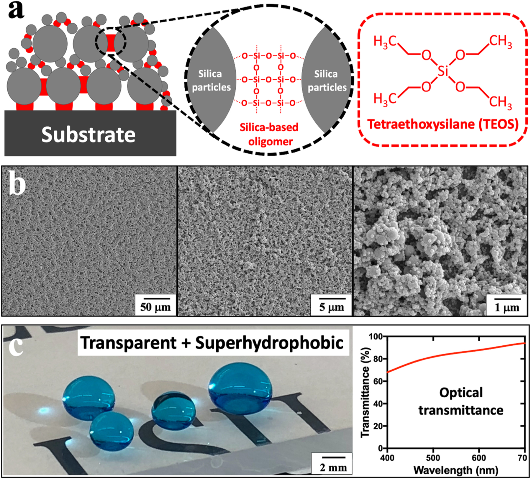
Fabrication of transparent and superhydrophobic microfluidic chips. (a) Schematics of the superhydrophobic coating layer containing silica-based oligomer and silica particles with strong anchoring on plastic substrate, and the chemical structure of TEOS that serves as a silica-based oligomer precursor. (b) SEM images of the superhydrophobic coating films with dual-sized silica particles (400/70 nm). (c) Optical image shows the methylene blue-dyed water droplets deposited on a transparent and superhydrophobic PMMA substrate, and its optical transmittance graph at the visible wavelength range (400–700 nm). Transmittance percentage is determined relative to pristine PMMA substrates.
To obtain a sharp wettability contrast at the edge of the microfluidic ports (500 μm in diameter), precise micromilling was performed for machining micro-holes while not to damage the superhydrophobic coating films (PMMA in Fig. 2a, PC in Fig. S8). In comparison, spin coating after machining micro-holes may cause the leaking of superhydrophobic coating solution into the port inner wall (Fig. S1). As verified by scanning electron microscopy (SEM) images, the inner wall of the microfluidic port was free of silica particles, representative of a hydrophilic pristine PMMA surface. In contrast, the peripheral of the microfluidic port was densely covered with silica particles, indicating a superhydrophobic coating film (Fig. 2b). Specifically, the static water contact angles (CAs) of PMMA before and after superhydrophobic silica coating were measured as 70° and 163°, respectively. Also, for PMMA substrates directly vapor deposited with PDTS without being coated with silica particles, the static water CAs were reduced from 166° (silica particles + PDTS) to 119° (Fig. S7). X-ray photoelectron spectroscopy (XPS) analysis further confirmed such a wettability contrast. In the XPS spectrum, the fluorine 1 s electron signal (689 eV) from fluorocarbon motif was clearly observed at the outer port peripheral, while no fluorine signal was detected at the inner port wall (Fig. 2c). Such a wettability contrast led to a preferential affinity of air bubbles to superhydrophobic surfaces over hydrophilic surfaces. For example, an in-air superhydrophobic surface is contrarily underwater bubble-philic and vice versa (Fig. 2d) [39,51]. Consequently, the superhydrophobic microfluidic port peripheral was highly attractive to air bubbles over aqueous liquids, and thus facilitating air escape via the air gaps. A similitude of wettability contrast was observed on PC substrates.
Fig. 2.
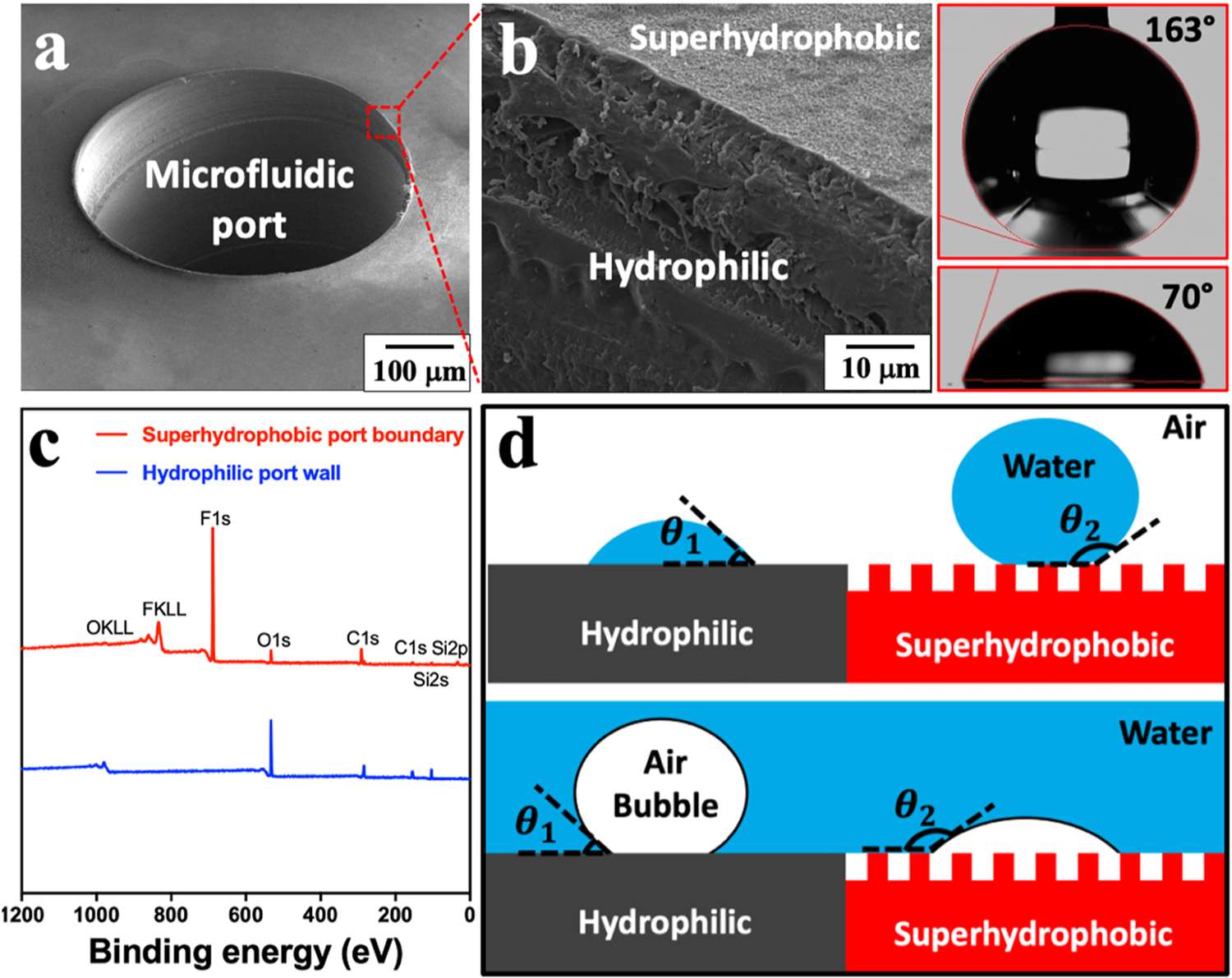
Sharp wettability contrast at the microfluidic port edge. (a) SEM image of a microfluidic port. (b) Close-up image shows the edge of the microfluidic port and the static water CAs before/after superhydrophobic silica coating. (c) XPS analysis on superhydrophobic port peripheral and hydrophilic inner port wall. (d) Schematics showing the interaction of in-air water droplets and underwater air bubbles with hydrophilic and superhydrophobic surfaces, respectively.
The microfluidic assembly was fabricated via a well-established double-sided micro-embossing method [40–42,50] and served as a proof-of-concept test platform. The micro-embossing parameters for both PMMA and PC substrates were detailed in Table 1. This microfluidic test platform included two microfluidic modules mounted on a motherboard, which was assembled with the assistance of built-in pin-in-V-groove structures and embedded magnets. Pin-in-V-groove structures were pre-embossed onto the plastic microfluidic substrates, in which they simultaneously aligned the microfluidic ports as well as maintained the air gap distance [42,43]. Briefly, three pairs of hemisphere-tipped pins and V-shaped grooves were employed to constrain the relative motion between two paired microfluidic chips (Fig. 3d). Confocal microscopic imaging confirmed the low variations in air gap distances (10 ± 2 μm) and the port-to-port misalignments (59 ± 13 μm) for each pair of microfluidic ports. The embedded magnets served to passively clamp two PMMA chips, which enabled a passive chip-to-chip assembling (Fig. 3e). According to the Original K&J Magnet Calculator (K&J Magnetics, Inc., Pipersville, PA, USA) [44], four pairs of circular N52 magnets (10 μm gap distance) theoretically provide roughly 3.4 N pulling force, which was sufficiently high for our centimeter-sized microfluidic chips. When a liquid analyte went through a microfluidic interconnect, liquid bridge was spontaneously formed, and the lateral leakage was prevented by superhydrophobic peripheral sealing (Fig. 3a,b). In addition, the microfluidic modules were designed to be air bubble-prone owing to their serpentine microchannels and high density micropillar structures (Fig. 3c). That is, a small variation in the microchannel widths or micropillar spacings would cause the fluctuations of the Laplace pressure resistance, leading to the selective blocking/delaying of fluidic flow and consequently the formation of air bubbles (Fig. S2).
Table 1.
Micro-embossing parameters for PMMA and PC substrates.
| Glass transition temperature (°C) | Molding temperature (°C) | Demolding temperature (°C) | Pressing force (kN) | Holding time (min) | |
|---|---|---|---|---|---|
| PMMA | 105 | 160 | 90 | 20 | 2 |
| PC | 147 | 195 | 140 | 25 | 2 |
Fig. 3.
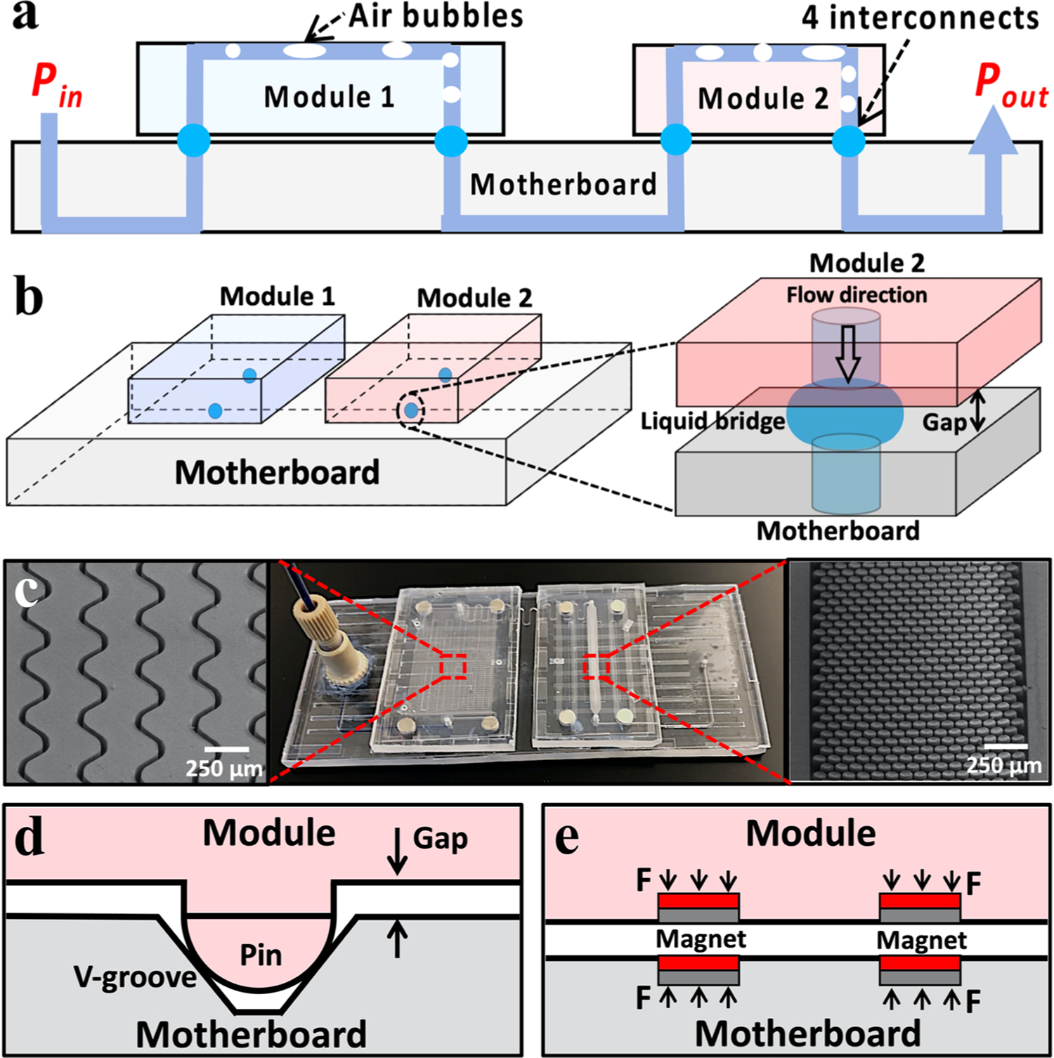
Proof-of-concept microfluidic setup for air bubble removal. (a) 2D and (b) 3D schematics showing proof-of-concept microfluidic assembly and close-up image showing the formation of liquid bridge between two assembled microfluidic chips. (c) Optical image of the microfluidic setup and SEM images of serpentine microchannels and high density micropillar structures in microfluidic modules. Schematics of (d) pin-in-V-groove structures and (e) built-in magnets for microfluidic port-to-port aligning and passive assembling.
Typical results for microfluidic sealing and air bubble eliminating were presented in Fig. 4. As mentioned above, the wettability contrast enabled a preferential fluidic entrance into the microfluidic ports while simultaneously eliminated air bubbles owing to the presence of air gaps (Fig. 4a). Importantly, the presence of chip-to-chip air gap would not introduce any new air bubbles into microfluidic systems, as the inner hydrophilic channel walls were air bubble phobic. This was further confirmed by the experimental observations on the microfluidic setup, where air bubbles were continuously removed after aqueous liquid passing through the microfluidic interconnects (Fig. 4b, Movie S1 for PMMA, Movie S2 for PC). For a typical flow test, a syringe and a custom-built computer-controlled syringe pump were employed to pump methylene blue-dyed deionized (DI) water (surface tension γ = 72.8 mN/m), fetal bovine serum (FBS, γ = 52.0 mN/m), and healthy donor plasma (γ = 55.9 mN/m) into the microfluidic assemblies at a flow rate of 5–200 μL/min. To estimate the maximum sealing pressure (or leakage pressure) of the microfluidic interconnects, we calculated the interfacial Laplace pressure according to the modified Young-Laplace equation: [45] ΔP ≈ γ/R = 2γcosθ/z, where R is the radius of curvature in normal plane, θ is the liquid static CA of the superhydrophobic surfaces (Table S1), γ is interfacial surface tension, and z is air gap distance. Taking zmax = 12 μm and zmin = 8 μm as aforementioned, the surface tension (γ) dependence of leakage pressure (ΔPleak) can be estimated for DI water, FBS, and healthy donor plasma (Fig. 4c). For experimental verification, our theoretical values were in a good agreement with the measured (by Elveflow pressure sensor) leakage pressures (Fig. 4d). Meanwhile, for microfluidic motherboard directly treated with PDFS without prior silica particle coating, the leakage pressure was also reported (Fig. S7). For a typical operation of the microfluidic interconnect, the liquid bridge meniscus was capable of changing shapes (i.e., radius of curvature R) and adapting to the real time liquid-air pressure difference. Nevertheless, such a pressure difference must be controlled below leakage pressure (ΔPleak) for the proper microfluidic operation. Additionally, we further characterized the volume distribution of individual air bubbles within microchannels (Fig. 4e). Note that the air bubble volume was calculated based on the length of air bubbles and the cross-sectional area of microchannels. We observed a smaller size range of air bubbles for FBS and heathy donor plasma, possibly owing to their lower surface tension and thus a reduced variation in interfacial Laplace pressure. Meanwhile, the air bubble removal efficiency in volumes was measured with varying flow rates and liquid analytes. For a typically experiment, the sum of air bubble length before and after passing though the interconnect was measured by optical imaging over a 5 min period, respectively. Since the microchannels on both module and motherboard have the same cross-sectional area, the air bubble removal efficiency was calculated by the fraction of overall bubble length at the outlet and inlet of the interconnect (Fig. S11). For all three types of liquids, we observed an air bubble removal efficiency > 95% with flow rates ranging from 5 to 200 μL/min (Figure f-h, Table S3). The unremoved air bubbles may be due to the following reasons: (1) the boost of flow rate and pressure at the beginning of liquid perfusion process; (2) the circular open-air interconnect with a complex solid-liquid-air interface; and (3) the air bubbles were not attached to the inner channel wall, which prevented them from being vented by the ‘bubble-philic’ superhydrophobic boundary surfaces at the interconnect. For comparison between the conditions with and without wettability contrast, we also conducted the flow of DI water (100 μL/min) into interconnect without superhydrophobic boundary coatings. That is, both interconnect port inner wall and boundary were maintained hydrophilic. As a result, we observed the leakage of DI water into air gaps but the wettability contrast-enabled interconnect remained sealed with no leakage (Fig. 5, Movie S3).
Fig. 4.
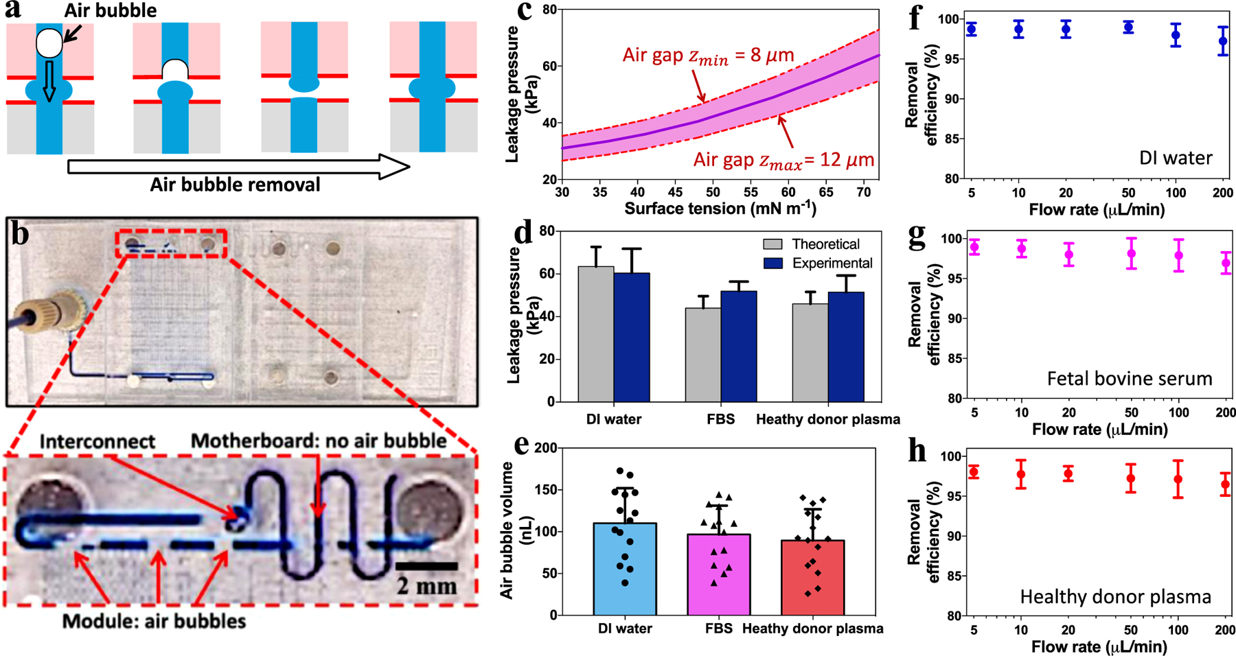
Results of sealing microfluidic interconnects and eliminating air bubbles. (a) Schematics illustrating the mechanism of air bubbles escaping via the air gap between two microfluidic chips. (b) The assembly of two microfluidic modules mounted on a motherboard, and the close-up view shows the air bubbles removal after passing through the microfluidic interconnect. (c) The theoretical leakage pressures (with upper and lower limits due to air gap variations) at the microfluidic interconnects for liquids of varying surface tensions. (d) The estimated and experimentally measured leakage pressures, (e) the volume distribution of individual air bubbles, and (f-h) air bubble removal efficiency vs. air bubble removal rate for DI water, FBS, and healthy donor plasma.
Fig. 5.
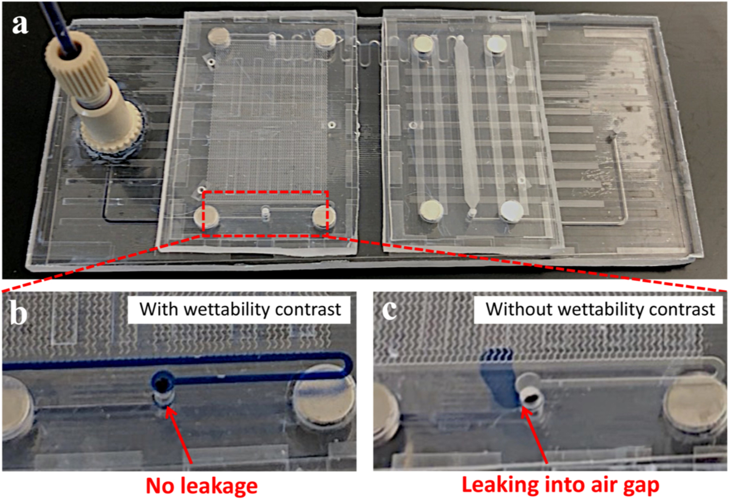
(a) The flow of blue-dyed DI water into microfluidic assembly with zoomed views of interconnects (b) with and (c) without wettability contrast.
Supplementary material related to this article can be found online at doi:10.1016/j.addma.2020.101681.
Supplementary material related to this article can be found online at doi:10.1016/j.addma.2020.101681.
Supplementary material related to this article can be found online at doi:10.1016/j.addma.2020.101681.
To understand the interfacial mechanism of air bubbles passing through microchannels and fluidic interconnects, we conducted theoretical analysis on their wetting properties and pressure resistance. The Jamin effect, which describes the gas bubble induced impedance on liquid flow through capillary tubes, is attributed to the hysteresis force caused by the difference between the advancing and receding CAs [46, 47]. Or in short, the presence of air bubbles within microchannels increases the shear resistance of fluidic flow. This Jamin effect is more evident at a smaller microchannel cross-section owing to the increased Laplace pressure. Due to the microscale channel dimension (250 × 500 μm) in our experiments, an air bubble usually spans the entire microchannel cross-section as observed from the microfluidic flow experiments (Fig. 4b, Movie S1). That is, a relatively large air bubble divides the liquid flow into two disconnected parts (Fig. 6a). Without loss of generality, let us consider an air bubble advances through a liquid-perfused microchannel. The receding contact angle (θrec) at the front of air bubble meniscus, and the advancing contact angle (θadv) at the back of air bubble meniscus, result in a pressure resistance (Fig. 6b): Presist = Padv – Prec = 4γ (cosθrec – cosθadv) /Dh, where Dh is the hydraulic diameter of microchannel [48]. Note that the interfacial pressure resistance for each individual air bubble remains unchanged with its length/volume, as long as it spans the entire microchannel cross-section (Fig. 6c). Meanwhile, we restricted our analysis to quasi-static equilibrium of air bubbles, without taking account into their dynamic contributions or surface frictions [5]. As a consequence, for a microchannel containing N discrete air bubbles, the total pressure resistance Ptotal = NPresist = 2Nγ(cosθrec – cosθadv)/Dh. By incorporating the microfluidic interconnect for air bubble removal, the air bubble-induced Ptotal can be thoroughly relaxed within microchannels. Importantly, the microfluidic interconnect is advantageous over conventional methods utilizing hydrophobic venting membranes in terms of air bubble removal efficiency, as evidenced from our experimental results showing approximately > 95% air bubble removal rate (Fig. 4f–h). Further, our interconnects show advantages in removing ultra-small air bubbles. For example, if an air bubble is smaller than the width of a microchannel, it cannot be removed by conventional strategies unless migrating at the vicinity of their venting structures (Fig. 6d). In contrast, the two fluidic ports in our interconnects are fully separated by an air gap, enabling efficient venting of tiny air bubbles at any adhered locations (Fig. 6e).
Fig. 6.
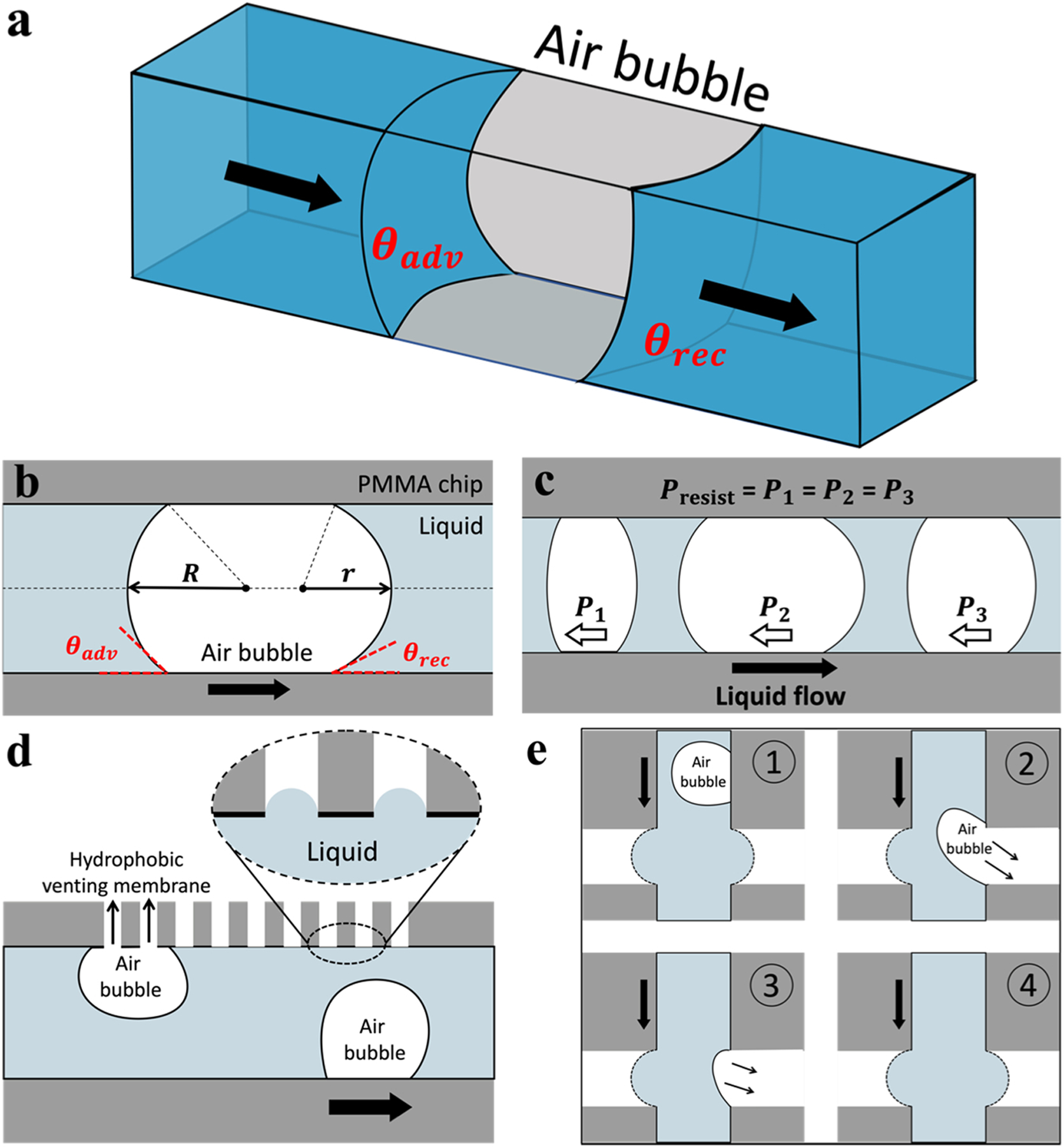
Interfacial analysis of air bubbles in microfluidic system. (a) 3-D schematic and (b) 2-D schematic of an air bubble spanning the entire cross-section of a liquid-perfused microchannel. The receding (θrec) and advancing (θadv) contact angles at the front and back of air bubble meniscus, respectively. (c) The air bubbles in a microchannel have the same pressure resistance regardless of their length/volume. Schematics showing air bubbles being removed by (d) conventional hydrophobic venting membrane and (e) wettability-contrast enabled microfluidic interconnect.
3. Conclusion
We have proposed a wettability contrast-governed strategy for air bubble removal in microfluidic systems, which was enabled by the sharp wetting contrast at the port edge of a microfluidic interconnect. We have demonstrated that air bubbles can be continuously removed from the liquid analytes of varying surface tensions within microfluidic systems. Meanwhile, no liquid leakage was observed at the microfluidic interconnect, representing an adequate chip-to-chip sealing by the transparent superhydrophobic boundary surfaces. We also discussed the potential advantage of this wettability strategy in terms of air bubble removal efficiency, when compared to conventional passive strategies utilizing porous microstructures/membranes. Further, the reported concept and strategy for wettability-contrast sealing and air bubble removing may be extended to more complex mixed-scale or Lego®-like microfluidic assemblies with high-density interconnects.
4. Experimental section
4.1. Materials
Polymethylmethacrylate (PMMA) (Cope Plastics, Alton, IL, 100 × 100 mm surface area, 3 mm thick) and polycarbonate (PC) (SABIC Innovative Plastics, Houston, TX, 100 × 100 mm surface area, 3 mm thick) were used as microfluidic substrate. Neodymium N52 magnets (8 mm in diameter; 1 mm in thickness) were purchased from Stritra. Anhydrous ethanol, 200 proof, was obtained from Decon Laboratories (Montco, PA). Tetraethyl orthosilicate (TEOS) was supplied by Acros Organics (98%) (Geel, Belguim). Ammonia (28–30%) and Hydrochloric acid (HCl) were purchased from VWR International (Radnor, PA). Methylene Blue was purchased from Aldon Corporation (Avon, NY). Perfluorodecyltrichlorosilane (FDTS) was obtained from Gelest, Inc (Morrisville, PA). Fetal bovine serum (FBS) and healthy donor plasma were received from Life Technologies (Caersbad, CA).
4.2. Synthesis of silica particles
Silica particles with nominal diameters of 70 nm and 400 nm were synthesized using the Stöber method [49]. For a typical synthesis route of 400 nm silica particles, we first prepared a mixture of 200 mL ethanol and 10 mL ammonia in a flask, then added with 7.5 mL TEOS dropwise while maintaining the magnetic stirring at 1000 rpm. Next, the mixture of TEOS/ethanol/ammonia was magnetically stirred at 600 rpm for 18 h at room temperature, followed by centrifuging and vacuum-drying overnight. Table S2 shows the volume of ethanol, ammonia, and TEOS used for synthesizing 400 nm and 70 nm silica particles.
4.3. Transparent superhydrophobic coating
The superhydrophobic coating procedures utilizing silica particles and silica-based oligomers were described previously [37]. Briefly, the silica-based oligomer solution was prepared by mixing TEOS (1 g), HCl (1 g), and ethanol (10 g), followed by magnetic stirring (700 rpm, 60 °C, 90 min). Next, 70 nm (0.25 g) and 400 nm (0.5 g) silica particles were dispersed into the oligomer solution and sonicated for 15 min. The obtained silica particle/oligomer mixture were spin coated (750 rpm) on the plastic substrates. The spin coated substrate was then oxygen plasma (30 W, 0.15 Torr, Harrick Plasma PDC-32 G) treated for 3 min, followed by vapor deposition of FDTS for low energy surface treatment.
4.4. Fabrication of microfluidic test platform
The brass molds used for embossing the microfluidic assembly, incorporating one module with serpentine-shaped microchannels (4 × 2.7 cm), the other module with high-density micropillars (4 × 2.4 cm), and a motherboard (10 × 4 cm), were designed using AutoCAD (AutoCAD® 2019. Autodesk, Inc., San Rafael, CA) (front and back, Fig. S3, S4). The AutoCAD designs of brass molds were then imported to GibbsCAM (3D Systems, Moorpark, CA) for subsequent micromilling by Kern Evo Ultra Precision CNC machining (KERN Microtechnik GmbH, Germany).
A single-step, double-sided hot-embossing method40 was used to replicate the microchannels, pin-in-V-groove structures, and fluidic ports in PMMA and PC substrates from the two brass molds. The pin-in-V-groove structures, which comprised of three pairs of hemisphere-tipped pin and a V-shaped grooves, have been demonstrated in our group as passive alignment features (to avoid over- and under-constraint) for modular microfluidic systems [43]. The micro-patterns were printed from the brass molds to a 3 mm thick PMMA or PC substrate using a Jenoptik HEX02 hot-embossing machine (Jena, Germany). The micro-embossing parameters for PMMA and PC including molding temperature, demolding temperature, pressing force, holding time are shown in Table 1. The open microfluidic channels were oven bonded by a 250 µm thick PMMA (108 °C) or PC coversheet (155 °C) for 1 h. The misalignment of the top and bottom micropatterns on the hot-embossed plastic substrates were measured by microscope, and the position of the brass molds was then adjusted to minimize the misalignment. Four magnets (3 mm in diameter; 1 mm in thickness) were embedded into each plastic module, and eight magnets were embedded into a plastic motherboard (Fig. 4b).
4.5. Fluidic leakage test
A syringe and a computer-controlled syringe pump were used to inject DI water, fetal bovine serum (FBS), and healthy donor plasma into the microfluidic system at 10 μL/min. FBS and health donor plasma were selected for potential analytical applications in cell isolation and detection. A commercial microfluidic pressure sensor (MPS; Elveflow, France) was connected to the microfluidic system to measure the fluid leakage pressures at the interconnects (Fig. S4). After the test liquids passing though the interconnect, the downstream flow valve was closed and maximum leakage pressure was recorded upon fluidic leakage. For each liquid type, at least 10 measurements of leakage pressure were conducted (Fig. 4d).
4.6. Characterization
The surface morphologies of the silica particle coatings were imaged using a Field Emission Gun Scanning Electron Microscope (FEG-SEM, The quanta 3D DualBeam). Prior to SEM imaging, the surface surfaces were sputtered with roughly 10 nm platinum layer (EMS550X sputter coater) to improve electrical conductivity and reduce charging effect. Contact angles (CAs) were measured by a VCR Optima goniometer (AST Products, Inc.) and a droplet shape software (VCA Optima XE, AST Products), using a sessile droplet technique. The static CAs was measured by depositing a 10 μL droplet of liquids onto sample surfaces using a microsyringe. CAH was recorded as the difference of the advancing and receding CAs, which were obtained by adding and removing liquids from the sample surface. X-ray photoelectron spectroscopy (XPS) analysis was performed using a Scienta Omicron ESCA 2SR X-ray Photoelectron Spectroscope with an aluminum monochromatic source. The transmittance spectra of were obtained using a Thermo Electron Helios UV–Vis spectrophotometer (Thermo Electron Corp.) in the visible wavelength range (400–700 nm). The transmittance percentage of the silica particle coatings was based on the uncoated PMMA/PC substrates.
Supplementary Material
Acknowledgments
This project was supported by the National Institute of Biomedical Imaging and Bioengineeing of the National Institutes of Health through a Biotechnology Resource Center Grant P41-EB-020594, the State of Louisiana Board of Regents Enhancement Program LEQSF (2015–2016)-ENH-TR-16, the Louisiana Governor’s Biotechnology Initiative, and the LSU Department of Mechanical & Industrial Engineering, through the Roy O. Martin Jr. Lumber Co. Professorship of Mechanical Engineering.
Biography
Xiaoxiao Zhao obtained my Ph.D. in Mechanical Engineering from Louisiana State University, and his research focuses on superhydrophobic coatings, lab-on-a-chip devices, and nano-imprinting techniques. His overall goal is to leverage interfacial surface science to overcome challenges in energy efficiency, sustainability, and biology.
Footnotes
CRediT authorship contribution statement
Xiaoxiao Zhao: Conceptualization, Methodology, Writing – original draft preparation. Chenbo Ma: Writing – review & editing. Daniel S. Park: Writing – review & editing. Steven A. Soper: Writing – review & editing. Michael C. Murphy: Conceptualization, Writing – review & editing.
Declaration of Competing Interest
The authors declare the following financial interests/personal relationships which may be considered as potential competing interests, Xiaoxiao Zhao reports was provided by Louisiana State University and Nanjing Forestry University. Xiaoxiao Zhao reports a relationship with Louisiana State University and Nanjing Forestry University that includes:.
Appendix A. Supporting information
Supplementary data associated with this article can be found in the online version at doi:10.1016/j.snb.2022.131687.
References
- [1].Lochovsky C, Yasotharan S, Günther A, Bubbles no more: in-plane trapping and removal of bubbles in microfluidic devices, Lab Chip 12 (2012) 595–601. [DOI] [PubMed] [Google Scholar]
- [2].Born C, Zhang Z, Al-Rubeai M, Thomas CR, Estimation of disruption of animal cells by laminar shear stress, Biotechnol. Bioeng 40 (1992) 1004–1010. [DOI] [PubMed] [Google Scholar]
- [3].Zhao Y, Cho SK, Micro air bubble manipulation by electrowetting on dielectric (EWOD): transporting, splitting, merging and eliminating of bubbles, Lab Chip 7 (2007) 273–280. [DOI] [PubMed] [Google Scholar]
- [4].Gravesen P, Branebjerg J, Jensen OS, Microfluidics-a review, J. Micromech. Microeng 3 (1993) 168–182. [Google Scholar]
- [5].Jensen MJ, Goranović G, Bruus H, The clogging pressure of bubbles in hydrophilic microchannel contractions, J. Micromech. Microeng 14 (2004) 876–883. [Google Scholar]
- [6].Elwenspoek M, Lammerink TSJ, Miyake R, Fluitman JHJ, Towards integrated microliquid handling systems, J. Micromech. Microeng 4 (1994) 227–245. [Google Scholar]
- [7].Nakayama T, Kurosawa Y, Furui S, Kerman K, Kobayashi M, Rao SR, Yonezawa Y, Nakano K, Hino A, Yamamura S, Circumventing air bubbles in microfluidic systems and quantitative continuous-flow PCR applications, Anal. Bioanal. Chem 386 (2006) 1327–1333. [DOI] [PubMed] [Google Scholar]
- [8].Nakayama T, Hiep HM, Furui S, Yonezawa Y, Saito M, Takamura Y, Tamiya E, An optimal design method for preventing air bubbles in high-temperature microfluidic devices, Anal. Bioanal. Chem 396 (2010) 457–464. [DOI] [PubMed] [Google Scholar]
- [9].Stucki JD, Guenat OT, A microfluidic bubble trap and oscillator, Lab Chip 15 (2015) 4393–4397. [DOI] [PubMed] [Google Scholar]
- [10].Zheng W, Wang Z, Zhang W, Jiang X, A simple PDMS-based microfluidic channel design that removes bubbles for long-term on-chip culture of mammalian cells, Lab Chip 10 (2010) 2906–2910. [DOI] [PubMed] [Google Scholar]
- [11].Liu C, Thompson JA, Bau HH, A membrane-based, high-efficiency, microfluidic debubbler, Lab Chip 11 (2011) 1688–1693. [DOI] [PubMed] [Google Scholar]
- [12].Hosokawa K, Shimoyama I, Miura H, Two-dimensional micro-self-assembly using the surface tension of water, Sens. Actuators A Phys 57 (1996) 117–125. [Google Scholar]
- [13].Lee J, Kim C-J, An improved anodic bonding process using pulsed voltage technique, J. Micro Syst 9 (2000) 171–180. [Google Scholar]
- [14].Shih C, Lee LJ, Analysis of void removal in liquid composite molding using microflow models, Polym. Compos 23 (2002) 120–131. [Google Scholar]
- [15].Blackmore B, Li D, Gao J, Detachment of Bubbles in Slit Microchannels by Shearing Flow, J. Colloid Interface Sci 241 (2001) 514–520. [Google Scholar]
- [16].Lai Y, Lin L, Pan F, Huang J, Song R, Huang Y, Lin C, Fuchs H, Chi L, Bioinspired patterning with extreme wettability contrast on TiO2 nanotube array surface: a versatile platform for biomedical applications, Small 9 (2013) 2945–2953. [DOI] [PubMed] [Google Scholar]
- [17].Kamei J, Saito Y, Yabu H, Biomimetic ultra-bubble-repellent surfaces based on a self-organized honeycomb film, Langmuir 30 (2014) 14118–14122. [DOI] [PubMed] [Google Scholar]
- [18].Cheng H-B, Lu Y-W, Applications of textured surfaces on bubble trapping and degassing for microfluidic devices, Microfluid. Nanofluidics 17 (2014) 855–862. [Google Scholar]
- [19].Pereiro I, Khartchenko AF, Petrini L, Kaigala GV, Nip the bubble in the bud: a guide to avoid gas nucleation in microfluidics, Lab Chip 19 (2019) 2296–2314. [DOI] [PubMed] [Google Scholar]
- [20].Liu H-B, Gong H-Q, Ramalingam N, Jiang Y, Dai C-C, Hui KM, Micro air bubble formation and its control during polymerase chain reaction (PCR) in polydimethylsiloxane (PDMS) microreactors, J. Micromech. Microeng 17 (2007) 2055–2064. [Google Scholar]
- [21].Johnson M, Liddiard G, Eddings M, Gale B, Bubble inclusion and removal using PDMS membrane-based gas permeation for applications in pumping, valving and mixing in microfluidic devices, J. Micromech. Microeng 19 (2009) 95011. [Google Scholar]
- [22].Kang JH, Kim YC, Park J-K, Analysis of pressure-driven air bubble elimination in a microfluidic device, Lab Chip 8 (2008) 176–178. [DOI] [PubMed] [Google Scholar]
- [23].Skelley AM, Voldman J, An active bubble trap and debubbler for microfluidic systems, Lab Chip 8 (2008) 1733–1737. [DOI] [PubMed] [Google Scholar]
- [24].Sung JH, Shuler ML, Prevention of air bubble formation in a microfluidic perfusion cell culture system using a microscale bubble trap, Biomed. Micro 11 (2009) 731–738. [DOI] [PubMed] [Google Scholar]
- [25].Meng DD, Kim J, Kim C-J, A degassing plate with hydrophobic bubble capture and distributed venting for microfluidic devices, J. Micromech. Microeng 16 (2006) 419–424. [Google Scholar]
- [26].Cheng Y, Wang Y, Ma Z, Wang W, Ye X, A bubble- and clogging-free microfluidic particle separation platform with multi-filtration, Lab Chip 16 (2016) 4517–4526. [DOI] [PubMed] [Google Scholar]
- [27].Chang F-M, Sheng Y-J, Cheng S-L, Tsao H-K, Tiny bubble removal by gas flow through porous superhydrophobic surfaces: Ostwald ripening, Appl. Phys. Lett 92 (2008), 264102. [Google Scholar]
- [28].Cortes DF, Tang T-X, Capelluto DGS, Lazar IM, Nanoflow valve for the removal of trapped air in microfluidic structures, Sens. Actuators B Chem 243 (2017) 650–657. [Google Scholar]
- [29].He X, Wang B, Meng J, Zhang S, Wang S, How to Prevent Bubbles in Microfluidic Channels, Langmuir 37 (2021) 2187–2194. [DOI] [PubMed] [Google Scholar]
- [30].Huang C, Wippold JA, Stratis-Cullum D, Han A, Eliminating air bubble in microfluidic systems utilizing integrated in-line sloped microstructures, Biomed. Micro 22 (2020) 1–9. [DOI] [PubMed] [Google Scholar]
- [31].Kobrin B, Nowak R, Chinn J and Yi R, 2006.
- [32].Kiryukhin MV, Lau HH, Lim SH, Salgado G, Fan C, Ng YZ, Leavesley DI, Upton Z, Arrays of Biocompatible and Mechanically Robust Microchambers Made of Protein-Polyphenol-Clay Multilayer Films, ACS Biomater. Sci. Eng 6 (2020) 5653–5661. [DOI] [PubMed] [Google Scholar]
- [33].Cassie ABD, Baxter S, Wettability of porous surfaces, Trans. Faraday Soc 40 (1944) 546. [Google Scholar]
- [34].Zhao X, Park DS, Choi J, Park S, Soper SA and Murphy MC, J. Colloid Interface Sci, DOI: 10.1016/j.jcis.2020.04.065. [DOI] [Google Scholar]
- [35].Zhao X, Khandoker MAR, Golovin K, Non-fluorinated omniphobic paper with ultralow contact angle hysteresis, ACS Appl. Mater. Interfaces 12 (2020) 15748–15756. [DOI] [PubMed] [Google Scholar]
- [36].Yoo D, Kang K, Kim Y, Ahn H, Lee W, Pak J, Chung S, Lee T, Solution-processed transparent superhydrophobic protection layers for enhancing the device reliability of flexible organic optoelectronics, Adv. Mater. Technol 5 (2020), 2000449. [Google Scholar]
- [37].Zhao X, Soper SA and Murphy MC, Colloids Surfaces A Physicochem. Eng. Asp, DOI: 10.1016/j.colsurfa.2021.126810. [DOI] [PMC free article] [PubMed] [Google Scholar]
- [38].Zhao X, Park DS, Choi J, Park S, Soper SA, Murphy MC, Flexible-templated imprinting for fluorine-free, omniphobic plastics with re-entrant structures, J. Colloid Interface Sci 585 (2021) 668–675. [DOI] [PMC free article] [PubMed] [Google Scholar]
- [39].Cao M, Li Z, Ma H, Geng H, Yu C, Jiang L, Is superhydrophobicity equal to underwater superaerophilicity: regulating the gas behavior on superaerophilic surface via hydrophilic defects, ACS Appl. Mater. Interfaces 10 (2018) 20995–21000. [DOI] [PubMed] [Google Scholar]
- [40].Xu F, Datta P, Wang H, Gurung S, Hashimoto M, Wei S, Goettert J, McCarley RL, Soper SA, Polymer microfluidic chips with integrated waveguides for reading microarrays, Anal. Chem 79 (2007) 9007–9013. [DOI] [PMC free article] [PubMed] [Google Scholar]
- [41].Park DS, Witek M, Zhao X, Kang Y, Dathathreya K, You BH, Soper SA, Murphy MC, ASME International Mechanical Engineering Congress and Exposition, vol. 59476, American Society of Mechanical Engineers, 2019. V010T12A015. [Google Scholar]
- [42].Zhao X, Park DS-W, Soper SA, Murphy MC, J. Micro Syst (2020) 1–6. [DOI] [PMC free article] [PubMed] [Google Scholar]
- [43].You BH, Chen P-C, Park DS, Park S, Nikitopoulos DE, Soper SA, Murphy MC, Passive micro-assembly of modular, hot embossed, polymer microfluidic devices using exact constraint design, J. Micromech. Microeng 19 (2009), 125025. [Google Scholar]
- [44].Yuen PK, A reconfigurable stick-n-play modular microfluidic system using magnetic interconnects, Lab Chip 16 (2016) 3700–3707. [DOI] [PubMed] [Google Scholar]
- [45].Hibara A, Iwayama S, Matsuoka S, Ueno M, Kikutani Y, Tokeshi M and Kitamori T, Anal. Chem, DOI: 10.1021/ac0490088. [DOI] [PubMed] [Google Scholar]
- [46].Jamin J, Comptes Rendus Acad. Sci. Fr 50 (1860) 172. [Google Scholar]
- [47].Smith WO, Crane MD, The jamin effect in cylindrical tubes, J. Am. Chem. Soc 52 (1930) 1345–1349. [Google Scholar]
- [48].Lewis AM, Measuring the hydraulic diameter of a pore or conduit, Am. J. Bot 79 (1992) 1158–1161. [DOI] [PubMed] [Google Scholar]
- [49].Stöber W, Fink A, Bohn E, Controlled growth of monodisperse silica spheres in the micron size range, J. Colloid Interface Sci 26 (1968) 62–69. [Google Scholar]
- [50].Brown CR, Zhao X, Park T, Chen P, You B, Park DS, Soper SA, Baird A, Murphy MC, Leakage pressures for gasketless superhydrophobic fluid interconnects for modular lab-on-a-chip systems, Microsystems & nanoengineering 7 (2021) 1–14. [DOI] [PMC free article] [PubMed] [Google Scholar]
- [51].Xia Y, Li R, Gao X, Influence of Surface Wettability on Bubble Formation and Motion, Langmuir 37 (49) (2022) 14483–14490. [DOI] [PubMed] [Google Scholar]
Associated Data
This section collects any data citations, data availability statements, or supplementary materials included in this article.


