

Abstract
Spinal screw placement is a challenging task due to small bone corridors and high risk of neurological or vascular complications, benefiting from precision guidance / navigation and quality assurance (QA). Implicit to both guidance and QA is the definition of a surgical plan – i.e., the desired trajectories and device selection for target vertebrae – conventionally requiring time-consuming manual annotations by a skilled surgeon. We propose automation of such planning by deriving the pedicle trajectory and device selection from a patient’s preoperative CT or MRI.
An atlas of vertebrae surfaces was created to provide the underlying basis for automatic planning – in this work, comprising 40 exemplary vertebrae at three levels of the spine (T7, T8, and L3). The atlas was enriched with ideal trajectory annotations for 60 pedicles in total. To define trajectories for a given patient, sparse deformation fields from the atlas surfaces to the input (CT or MR image) are applied on the annotated trajectories. Mean value coordinates are used to interpolate dense deformation fields. The pose of a straight trajectory is optimized by image-based registration to an accumulated volume of the deformed annotations. For evaluation, input deformation fields were created using coherent point drift (CPD) to perform a leave-one-out analysis over the atlas surfaces.
CPD registration demonstrated surface error of 0.89 ± 0.10 mm (median ± interquartile range) for T7/T8 and 1.29 ± 0.15 mm for L3. At the pedicle center, registered trajectories deviated from the expert reference by 0.56 ± 0.63 mm (T7/T8) and 1.12 ± 0.67 mm (L3). The predicted maximum screw diameter differed by 0.45 ± 0.62 mm (T7/T8), and 1.26 ± 1.19 mm (L3). The automated planning method avoided screw collisions in all cases and demonstrated close agreement overall with expert reference plans, offering a potentially valuable tool in support of surgical guidance and QA.
Keywords: Atlas registration, pedicle screw, image-guided surgery, quality assurance, surgical guidance, spine surgery, automatic planning
1. Introduction
Spinal pedicle screws are placed for purposes of spine fixation in a broad spectrum of surgical interventions addressing trauma, scoliosis, spondylolisthesis, and degenerative instability. Typically, screws are placed bilaterally via posterior approach in two or more vertebrae as anchors for fusion hardware (rods or plates). For stabilization, rods are attached to the transpedicle screws by locking channels within the screw heads, and for deformity correction, the rods are bent to the desired spinal curvature. The main challenge in such surgery is accurate placement of screws within the narrow corridor of the pedicle, a small bone structure adjacent to the spinal cord, nerve bundles, and blood vessels. Breach of the pedicle can damage nerve roots, the dural sac, vascular structures, and pleura (Attar et al., 2001). Medial breach of the spinal canal / cord is particularly hazardous and can cause paralyzation. In a meta-analysis covering 37,337 pedicle screw placements (Kosmopoulos and Schizas, 2007), misplacements were reported in 8.7% of screw insertions. Lower breach rates have also been reported – for example, 5.1% of 4790 screws by (Lonstein et al., 1999) and 1.7% of 6816 screw placements by (9.0% of patients) (Parker et al., 2011). In the meta-analysis of (Kosmopoulos and Schizas, 2007), 0.0-2.0% of patients in 36 studies reported neurological complications. This agrees with reports showing a 2.4% complication rate (Lonstein et al., 1999) and 0.9% revisions (Parker et al., 2011). With nearly 500,000 spinal fusion cases performed in the U.S. each year (Weiss et al., 2014), even a low percentage can amount to a large number of avoidable errors – for example, 2.0% equates to nearly 10,000 cases per year with neurological complications, and 1.0% revision rate equates to nearly 5000 avoidable repeat surgeries (at a cost of ~$24,000 each (Watkins et al., 2010)).
To improve the accuracy and precision of screw placement, surgical navigation systems have been developed to provide real-time 3D virtual representation of the screw trajectory with respect to preoperative CT or MRI (Peters, 2006). The last decade also saw broader introduction of intraoperative 3D imaging to permit visualization within a more up-to-date anatomical scene (Ritschl et al., 2016), (Silbermann et al., 2011), (Schafer et al., 2011), (Zhang et al., 2009), (Siewerdsen et al., 2005). Such capability also gives opportunity to detect and localize surgical implants (Görres et al., 2014), (Pauwels et al., 2013) for the purpose of quality assurance (QA). Recently, a method for accurate 3D localization of spinal screws from 2D fluoroscopic views has also been proposed as a means of both guidance and QA of the surgical product (Uneri et al., 2015). For these purposes, the measured position of the implanted device(s) is compared to the desired position – i.e., to a surgical plan. For pedicle screws, manual annotation of desired trajectories is certainly possible – e.g., simple linear trajectories defined in preoperative CT or MRI; however, manual definition of trajectories introduces a somewhat time-consuming and largely unacceptable addition to standard workflow. We address this shortfall by developing a method for automatic pedicle trajectory planning.
Previous work demonstrated automated trajectory estimation for spine screws by aligning a line to the pedicle shape (Wicker and Tedla, 2004). In subsequent work (Lee et al., 2012), trajectories were optimized with respect to a safety margin. This concept was extended by further considering screw fixation strength in planning (Daemi et al., 2015), and further work (Knez et al., 2016) proposed an image-based concept of fastening strength based on Hounsfield units. In (Solitro and Amirouche, 2016), a set of geometrical constraints was presented to provide an ideal trajectory for manually provided surface annotations. Despite such progress, automatic planning has not incorporated certain requirements implicit in surgical approach, such as realistic accessibility of the entry point and expert (sometimes intangible gestalt) understanding on how to obtain screw purchase (or in some cases, even purposeful breach) in the lateral cortex of the pedicle (rather than placing the screw in the center of the pedicle). Previous methods optimize with respect to knowledge restricted to pedicle geometry or bone density and so may indicate trajectories that are not practically accessible – e.g., entry-point location within a joint space – or simply assume that the center of the pedicle represents the best path. We instead follow the idea of a general geometric concept with respect to the patient’s vertebra shape, proven to result in excellent clinical outcome as reported in the work of (Parker et al., 2011). In their work, parts of the vertebra shape are simplified to geometric entities like planes, triangles, and single anatomical landmarks, used to constrain the trajectory by orthogonality and parallelism. Rather than manually defining and assessing such geometric entities, we statistically derive the geometric concept automatically from a set of vertebra shapes with well-defined trajectories. As described below, we report a method that computes a trajectory based on previously defined expert reference trajectories within an anatomical atlas, and to the extent that the reference trajectories incorporate such considerations of expert approach, so too will the automatically planned trajectory.
The development and evaluation of an automatic pedicle screw planning method is detailed below. The method is based upon an anatomical atlas of vertebral surfaces within which expert reference pedicle trajectories have been defined. Automatic planning is achieved by interpreting nonrigid surface deformation of the atlas to a particular patient’s CT or MR image. The reference trajectories are transferred to the patient image via the same nonrigid transformations and probabilistically aggregated to determine an automatically planned trajectory that reflects the principles of the reference trajectory – e.g., practical entry points and tendency toward screw purchase on the lateral cortex. In combination with previous work of automatic CT vertebra segmentation as summarized in (Yao et al., 2016) and systems for surgical guidance and QA, the resulting trajectory provides an important element with minimal addition to surgical workflow.
2. Methods
We present an atlas-based technique to determine an estimate for pedicle screw trajectory based on expert-defined reference trajectories. The method automatically estimates the points of entry and anterior-most extent for the transpedicle trajectory from a set of sparse deformation fields that transform vertebra surfaces from a previously defined atlas to the patient’s vertebrae, created from manual segmentations in CT/MRI or as commonly available in semi-automatic surface-to-image registration approaches (Castro-Mateos et al., 2015), (Rasoulian et al., 2013), (Seitel et al., 2015). The method also yields the maximum length and diameter of a screw that can be placed on the trajectory without breach of the medial, lateral, or anterior cortex. Therefore, the method facilitates streamlined planning of pedicle screw selection and placement.
The process is illustrated in Figure 1, with a glossary of notation provided in Table 1. The method draws from an atlas containing two important elements of prior knowledge: (i) an ensemble of vertebra shapes (surfaces defined by vertices Vi); and (ii) expertly defined transpedicle trajectories therein (point annotations, ti). Three registration steps detailed in subsections below are used to transfer this knowledge to the patient-specific input surface segmentation (denoted P): (1) each atlas surface Vi is non-rigidly deformed to the input shape P by point-based registration; (2) cylinder meshes Ci, representing the pedicle screws, are created from the trajectory annotations ti and deformed using the non-rigid registration resulting from (1), and an overlap distribution of the deformed cylinders is accumulated voxel-by-voxel in the coordinate frame of P; and (3) a straight cylinder (binary) I is rigidly registered to the accumulation function A to maximize overlap. The last step implicitly optimizes according to the importance of certain regions along the trajectory, e.g., the narrow region of the pedicle neck, where less variation in trajectory definition can be tolerated compared to other regions (e.g., inside the vertebra body).
Figure 1.

Overall workflow of the pedicle screw planning method.
Table 1.
Summary of variables in the automatic planning method.
| Variable | Description |
|---|---|
| Input surface (patient-specific segmentation from CT or MRI) with vertices pk where k is a vertex index | |
| Atlas member index referring to a set of n similar shapes, e.g. vertebrae of level 3, or of level 7 merged with level 8 | |
| Annotation categories including entry point (e), anterior-most extent of a non-breaching trajectory (a), and pedicle center (p) | |
| Surface for atlas member i | |
| Annotated point in a category j of an atlas member i | |
| Mean value coordinate of annotated point in a category j of an atlas member i | |
| Non-rigid displacement transformation mapping atlas member Vi to surface P | |
| Annotated point in a catergory j, transformed using the deformation field | |
| Mean (over i) of transformed annotations | |
| Non-breaching transpedicle trajectory comprising an entry point and anterior-most extent of the trajectory in atlas member i | |
| Cylinder surface modelling the volumetric extent of atlas trajectory ti | |
| Deformed cylinder surface, with each vertex transformed using the deformation Ti | |
| Binary image of deformed cylinder surface for a padded bounding box described by length (l), width (w), and height (h) | |
| Cylinder surface based on mean of transformed annotations | |
| Accumulation map for a padded bounding box described by length (l), width (w), and height (h) | |
| Rigid transform parameters: translation and rotation | |
| Rigid transform matrix based on z | |
| Point locations (entry, anterior) on the estimated trajectory relative to P | |
| Trajectory projected on reference (evaluation of anterior and entry point) | |
| Reference projected on trajectory (evaluation at pedicle center) | |
| α ∈ [0°, 180°) | Angle between reference and planned trajectory |
2.1. Atlas of vertebrae and trajectories
An atlas of n vertebral surfaces is created from 3D image segmentations. Details of the source data, number of atlas members, and particular vertebrae analyzed in the current work are provided in Section 2.4, below. For each member of the atlas i, a closed surface Vi is generated with annotations of categories j ∈ {a, e, p}, referring to anterior (a), entry (e), and pedicle center (p). The atlas also includes transpedicle trajectories ti for each atlas member, defined by the line , where defines the entry point and the anterior-most extent of the trajectory without breach of the anterior cortex. For purposes of evaluation, the atlas also contains annotation of the pedicle center (which may or may not reside on the trajectory), taken as the center of the smallest pedicle area as presented in coronal slices. To allow volumetric deformations of the trajectory, a cylindrical surface Ci is generated from each trajectory ti by computing orthogonal discs at equidistant intervals along the trajectory. The vertices of the disc perimeters are then triangulated to a cylindrical surface mesh as shown in Fig. 1. Figure 2(a) illustrates the entry point , the anterior location , and the resulting cylindrical mesh trajectory.
Figure 2.
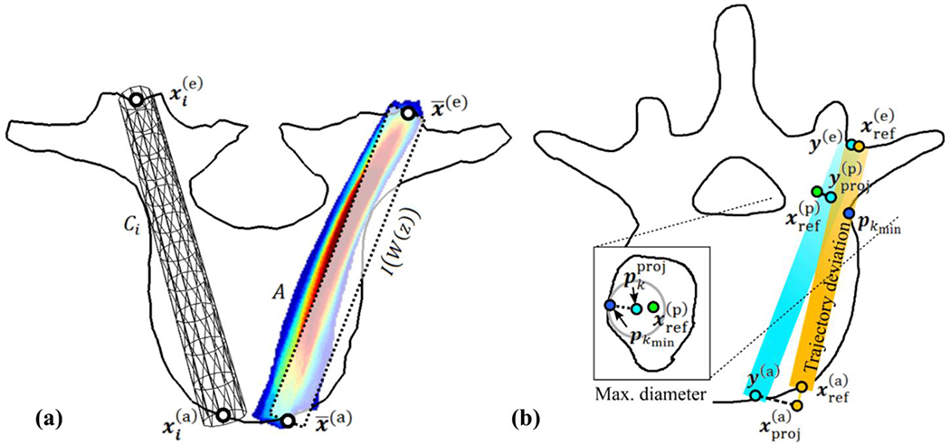
Illustration of pedicle screw (a) planning method and (b) analysis. (a) Definition of atlas trajectory (left) and accumulation function A (right). (b) Point-based deviation between the orange reference and estimated trajectories (y(e), y(a)) with axial cut (zoomed inset image) showing the maximal non-breaching radius determined by the distance from the center of the estimated trajectory to the closest vertex pkmin on the patient-specific surface P on the coronal slice containing (left).
In order to relate pre-operative clinical image input (CT or MRI) to the atlas, a vertebra segmentation or surface-to-image registration is required to obtain the modality-independent input surface P. A large variety of methods has been published in the last decade, allowing accurate vertebra detection and segmentation in CT data (Castro-Mateos et al., 2015), (Ibragimov et al., 2015), (Ma and Lu, 2013), (Korez et al., 2015), (Rasoulian et al., 2013), (Seitel et al., 2015). For the purpose of broad applicability, the following section takes the least structured shape representation (a binary segmentation) as input, which can be provided by any of these methods. As detailed below, all of the segmentations in the current work were derived from CT data. Surface-to-surface registration is performed to transfer the atlas knowledge and to provide measurements of registration error present throughout the experiments. This error allows to describe the required accuracy to obtain the trajectory quality achieved in this work. The error therefore allows to estimate feasibility of any surface-to-image registration method with integrated atlas representation used for regularization of local image-based vertex displacement estimates (Castro-Mateos et al., 2015), (Rasoulian et al., 2013), (Seitel et al., 2015). Such methods can provide the required set of sparse deformation fields Ti at any iteration with negligible computational cost. Direct integration of trajectory annotations into an atlas used for atlas-to-image registration was not investigated in the current work and remains of interest for future work.
2.2. Non-rigid surface deformation
Each atlas surface Vi is deformed to the input surface P using a displacement-based transformation Ti = cpd(Vi, P) computed using the Coherent Point Drift (CPD) algorithm (Myronenko and Song, 2010) to non-rigidly align the vertices of Vi to those of P such that Vi + Ti ≈ P. This method considers the alignment of two point sets as a probability density estimation: the centroids of a Gaussian mixture model (GMM) representing the vertices vk of Vi, k = 1, …, |Vi| are fit to the vertices pk of P, k = 1, …, |P| by maximum likelihood with |Vi|, |P| being the number of vertices in V, P. In this process, the GMM centroids are forced to move coherently as a group aiming at the preservation of topological structure. Coherence is achieved by regularizing the displacement field using a Gaussian kernel G with width β = 1:
| (1) |
For each vertex pair, a correspondence probability qμv is computed and stored in the matrix Q, for which an adjustable parameter, w = 0.1 nominally, describes the relative noise level in the data. The matrix
| (2) |
is iteratively updated and used to solve for a matrix of coefficients H|Vi|×3 in order to obtain the final transformations Ti = Vi + GH. A regularization parameter λ = 3 describes the trade-off between the maximum likelihood fit and the applied regularization:
| (3) |
where d−1(·) is the inverse diagonal matrix and 1 is the unity column vector. The Gaussian variance is initially defined by and updated in each iteration using the diagonal matrix d(·) and trace tr(·) in order to obtain:
| (4) |
In total, the three parameters of CPD affect its behavior with respect to noise (w), smoothness in regularization (β), and influence of the regularization (λ). The parameters selection was experimentally validated to achieve reasonable similarity of structures for all vertebrae, and these parameter settings were consistently used throughout the experiments below.
The CPD algorithm yields a sparse displacement field for each atlas surface to the input shape. To incorporate the effect of the deformation on the transpedicle trajectory within each vertebra, we invoked Mean Value Coordinates (MVC) (Ju et al., 2005) to interpolate a volumetric deformation field based on closed surfaces. The MVC approach deforms an annotation associated with an atlas surface Vi to the annotation relative to the deformed atlas shape Vi + Ti in Cartesian coordinates using a function m and its inverse m−1. The function m transforms Cartesian coordinates to mean value coordinates by incorporating projections of surface triangles onto the unit sphere of :
| (5) |
| (6) |
for which the triangles on the closed surface Vi defined by k′ ∈ {k − 1, k, k + 1} are projected on the unit sphere of . Three values θk′ define spherical edge lengths between projections of vk′. The vectors nk′ are inward unit normals, each computed for two of the obtained edges (Ju et al., 2005).
The estimated Mean Value Coordinates are weight coefficients in a linear combination of transformed vertices used in m−1 to estimate the corresponding annotation relative to Vi + Ti ≈ P as
| (7) |
with being the kth component of the coordinate vector being the kth vertex location component of the deformed surface Vi + Ti, and |Vi| being the number of vertices in Vi. This procedure is applied to each vertex in the cylinder surface Ci, leading to the deformed cylinder surface .
2.3. Estimation of transpedicle trajectory
By deforming the cylinder surfaces Ci, the entire volumetric extent of a pedicle screw trajectory is considered, allowing incorporation of knowledge about patient-specific vertebra shape along the trajectory. Therefore, if a trajectory represented by Ci in vertebra Vi goes through the pedicle narrowing, it will also go through the pedicle for the deformed cylinder surface in input vertebra P. We therefore optimize the pose of the trajectory with regard to the set of deformed cylinder surfaces by maximizing overlap volume. First, the cylinders are voxelized with isotropic voxel spacing of 0.25 mm. Each voxel o in the resulting binary image Bi is either 0 or 1 depending on whether it is outside or inside the deformed cylinder:
| (8) |
We then compute the trajectory determined by the accumulation of deformed cylinders by aggregating the binary images into an accumulation map:
| (9) |
as illustrated in Figure 2(a). To derive a trajectory from the accumulation map, we compute a rigid intensity-based registration of a straight binary cylindrical trajectory I (taken as the moving image) whose pose is altered to maximize its overlap with the accumulation map (taken as the fixed image). The moving image is simply a straight cylinder D derived from the mean entry point and mean anterior location , defined by:
| (10) |
The cylinder D is then voxelized to obtain the moving image I, which is registered to the accumulation map A using an intensity-based registration with gradient descent optimization. Transformation parameters z with 6 degrees of freedom (DoF) are optimized to obtain the transformation matrix W, which is applied to image I using linear interpolation. The sum of squared difference of intensity at each voxel defines the cost function:
| (11) |
The intensity values of I are multiplied by the number of atlas members n to match the maximally possible intensity in the accumulation map A, occurring at locations where all deformed trajectories overlap.
| (12) |
At each iteration μ, the discretely approximated derivative of the cost function is computed and added as a fraction to the parameters of the current iteration. This yields an update to the transformation given by:
| (13) |
We stop the optimization at 100 iterations as experimentally validated to converge for all cases. The resulting rigid transform W (z) is then applied on the mean entry and mean anterior point to yield the locations:
| (14) |
| (15) |
which represent the entry and anterior-most points, respectively of the estimated trajectory. Although the two resulting points define the final trajectory, they are not guaranteed to lie on the surface (as the input is not either), which is required for accurate guidance and measurement of screw length. A further step explained in section 2.5.3 below was used to derive the final locations on the surface.
2.4. Experimental design
The atlas was created using binary segmentations available in the public domain (SpineWeb1). We used dataset “number 2” (Yao et al., 2012) consisting of 10 thoracic and lumbar segmentations as well as dataset “number 5” (Ibragimov et al., 2014) consisting of 10 lumbar cases. Experiments reported below focused on vertebral levels T7, T8, and L3. Twenty atlas members were collected by merging the T7 and T8 data (referred to as T7/T8), and another twenty were collected by merging the L3 data from Spineweb datasets 2 and 5. Each atlas member (40 in total) was converted to a closed surface representation (triangulated mesh) and remeshed (Valette and Chassery, 2004) to obtain approximately |Vi| ≈ 2000 equidistant vertices on each. Each member of the atlas was augmented with a corresponding transpedicle trajectory defined by a fellowship-trained spinal neurosurgeon in CT data according to anatomical expertise and concepts described by Parker et al. (Parker et al., 2011). Level L3 was annotated with bilateral (left and right) trajectories, permitting investigation of screw collisions as described below. For the T7/T8 level, unilateral (left-side) trajectories were considered (and collisions were not specifically investigated, since trajectories at this level tend to be nearly parallel). For the resulting total of 60 trajectories in the atlas, three points were annotated manually: entry point , anterior location , and pedicle center , where the last was selected based on the smallest pedicle cross section visualized in coronal CT slices. The cylinder meshes Ci were created using 12 equidistant discs along the length of the trajectory, each perimeter sampled by 11 vertex points. The cylinder diameter was 5 mm for T7/T8 and 6 mm for L3. For each of the three pedicles, a leave-one-out cross-validation was conducted by constructing 20 separate atlases of 19 surface meshes and trajectories therein. Therefore, one sample (of vertebra surface and trajectory annotation) is left out of the atlas, and the 19 remaining surfaces are registered to the one vertebra surface. A new trajectory is estimated based on these 19 registrations together with the 19 atlas trajectories and then compared to the left-out trajectory annotation.
2.5. Automatic screw planning: Performance evaluation
2.5.1. Surface registration
The methodology described above yields a transpedicle trajectory that is automatically derived for a given, patient-specific vertebra surface. Assumed input are a valid segmentation of the patient-specific vertebrae (e.g., from preoperative CT or MRI) and corresponding labels (“T5,” “T6,” etc.) to provide basic correspondence with the atlas. The performance of the system is governed in part by the accuracy of the CPD non-rigid registration of each atlas member to the patient-specific surface. To evaluate registration accuracy, we compute the minimum distance between a vertex p on the input surface P to the closest vertex on the atlas surface Vi:
| (16) |
Based on this distance, the root mean square error is computed considering all vertices on the input surface P:
| (17) |
We evaluated this error using a cross-validation over the 20 vertebrae for each set (L3 and T7/T8) described above. In each leave-one-out step, input surface P ≔ Vref was selected and the 19 remaining surfaces Vi≠ref were non-rigidly registered to give drmse (Vref, Vi≠ref). Although this distance measure is not based on correspondence of vertices or anatomical landmarks in the image, the high density of vertices and the complex shape of vertebrae in general help to prevent the occurrence of a low variance for heavily misaligned surfaces (as would be possible for featureless shapes like spheres). The distance approximately quantifies the accuracy and describes the acceptable error in surface-to-image registration methods, for which this distance measure is commonly reported.
2.5.2. Screw trajectory
The main output of the process described above is an automatic estimate of transpedicle trajectory that could form the basis for planning and surgical navigation as well as comparison to intraoperative image updates by 3D2D registration (Uneri et al., 2015) and/or cone-beam CT (Schafer et al., 2011). The accuracy of the trajectory estimate, (y(e), y(a), was evaluated in comparison to the “reference” trajectory, tref, described above and illustrated in Figure 2(b). Several error measures regarding the orientation and dislocation of transpedicle trajectories were analyzed. In the leave-one-out evaluation, the left-out atlas member i was selected to be the reference. We denote the reference annotations by , which is the single selection ref = i for the current reference atlas member i. The angle between the reference and planned trajectory is then:
| (18) |
The orthogonal deviation from the reference trajectory was computed using vector projection represented by ω, where the calculated trajectory at position y(j) is projected onto the reference trajectory to obtain
| (19) |
as visualized at the bottom of Figure 2(b) by dashed lines. The distance is simply . In general, a trajectory does not (should not) necessarily go through the pedicle center, so the distance from center was not directly considered in the trajectory evaluation. However, since we are interested in the trajectory deviation at the location closest to the pedicle center, we evaluated as a surrogate of y(p) using the projected reference pedicle center:
| (20) |
to obtain the distances . Additionally, the Euclidean distance between the reference and mean of the transformed pedicle centers was measured to estimate the accuracy of in the input surface P based on mean value coordinates. This distance describes the error of estimating the pedicle center for unknown shapes and is the result of registration error, mean value interpolation error, and annotation error. It therefore describes the internal error of the presented approach to localize points inside the vertebra at the most vulnerable location: the pedicle center.
2.5.3. Maximum screw length
In addition to transpedicle trajectory, the method also yields important information such as maximum screw length dlen and maximum diameter d∅ that may be useful as decision support in device selection for a particular case. The maximum length is defined as the maximum distance along the trajectory that is inside bone – and in particular, does not breach the anterior cortex. An ideal case would imply this simply to be the Euclidean distance between the entry point and anterior location. However, since the atlas annotations are not forced to be perfectly on the surface, and since the rigid registration can slightly move points off the cortex (each introducing potential for small, ~voxel-level error), we instead intersect the trajectory line with the input surface P, and the two intersection points are used instead to measure the maximal length .
The trajectory lengths inside bone are first determined for the expert reference in order to demonstrate the maximum length possible for the anticipated trajectory. Since our goal is to compute a similar trajectory to the reference, we are interested in obtaining a similarly large maximum length for the automatic trajectory. Therefore, a pairwise difference was computed for each member of the atlas in the leave-one-out analysis. Negative (positive) values demonstrate a decreased (increased) length compared to the reference. Deviations were also compared using the characterization of commercially available screw types, limiting the resulting dlen, to nearest screw lengths ranging from 25 mm to 80 mm in 5 mm steps with two additional types of 90 mm and 100 mm length.
2.5.4. Maximum non-breaching screw diameter
In order to determine the maximum trajectory diameter that does not cause a breach, we iterate through the reference bone surface vertices pk ∈ P and check their shortest distance to the trajectory (y(e), y(a)). This concept is visualized in Figure 2(b), in which a small box shows the pedicle boundary in proximity to the annotated pedicle center. The distance between the trajectory color-coded in cyan and the closest vertex pkmin defines the maximum possible radius. To determine distances between vertices and a trajectory, the vertices were projected onto the estimated trajectory:
| (21) |
The vertex index kmin of the smallest distance between vertices pk and their projections on the trajectory was then determined by:
| (22) |
Thresholds of θ = 5 mm for T7/T8 and θ = 10 mm for L3 were used to ignore the cortex at the entry and anterior locations, because they do not affect the choice of screw diameter. The maximum diameter is then . Similar to the determination of maximum length, the maximum diameter was also first determined for the expert reference. The pairwise difference was computed with obtained by the same procedure as d∅, but using the reference trajectory instead. The values d∅, , and were then computed for each atlas member i in the leave-one-out analysis. Deviations were also compared using the characterization of commercially available screw types, limiting the results to screw diameters 4.0 mm, 5.0 mm, 5.5 mm, 6.0 mm, 7.0 mm, 8.0 mm, and 9.0 mm.
2.5.5. Screw collision investigation
To investigate, whether the computed trajectories implied undesirable screw collisions, a volume overlap between left and right trajectories was determined for various screw diameters and lengths following the specifications of commercially available screw types. The same range of screw diameters was investigated as for the maximum non-breaching screw diameter investigation, but the length was limited to vertebra sizes contained in the dataset: 45 mm to 70 mm. (See Figure 5 for different vertebra sizes). Volume overlaps were computed based on binarized cylinder surfaces (e.g., constructed in the same manner as Ci created for the estimated and reference trajectories of vertebra L3 to verify similar properties. Vertebrae T7/T8 were not investigated, since screw trajectories at these levels tend to be nearly parallel and not prone to collision.
Figure 5.

Visualization of all 60 reference (left subcolumns) and estimated (right subcolumns) trajectories in the experiment in relation to the vertebra shape. Three columns show the three trajectories (a) T7/T8 left, (b) L3 left, and (c) L3 right. The top row shows a set of rotated axial slices aligned to the trajectory. The bottom row shows rotated coronal slices at the pedicle center. The location of the coronal slices is highlighted in the top row by a thin line at the direction arrow color-coded in red.
3. Results
3.1. Accuracy of deformable registration
The overall surface distance error (median ± IQR) in deformably registering the atlas surfaces to the input surface was 0.87 ± 0.10 mm for T7/T8 and 1.29 ± 0.15 mm for L3. Figure 3 shows the individual error distributions in the leave-one-out analysis. The inter-case variation in the median error was less than 0.20 mm. A slightly higher median surface distance (0.87 mm versus 1.29 mm, p < 0.001) and IQR (0.10 mm versus 0.15 mm, p < 0.001) was evident for the L3 vertebrae as well as a larger variation between cases (standard deviations 0.06 ± 0.02 mm versus 0.07 ± 0.07 mm, p < 0.05). The colormap surface images in Figure 3 show the median distance to the closest vertices of 19 atlas vertebrae for two exemplary cases of T7 and L3. The results imply a relatively homogeneous distribution of registration error across the surface, with an increase in errors or outliers tending to arise about structures with high curvature. The systematic error to localize points inside the vertebra (including the mean value coordinate interpolation error) resulted in the accuracy 0.53 ± 0.75 mm (T7/T8 left), 0.93 ± 0.70 mm (L3 left), and 0.85 ± 0.85 mm (L3 right) at the pedicle center.
Figure 3.

Accuracy of deformable registration of atlas surfaces (leave-one-out analysis). (a) Error distributions for the T7/T8 (each left) and L3 (each right) vertebrae. The box and whisker plots show surface distance errors for 20 cases. (b) Surface rendering shows the distribution of registration errors for case #1.
3.2. Accuracy of transpedicle trajectories
The discrepancy between the estimated and reference trajectory is summarized in Table 2. For each case, we separately analyzed the error at the entry point, anterior location, and at the pedicle center. Consistent with the results of Figure 3, the errors were again slightly smaller for the T7/T8 vertebrae than for the L3. Pooling T7/T8 and L3 vertebrae, we observe a difference of (1.16 ± 1.02) mm at the entry point, (1.05 ± 0.74) mm at the pedicle center, and (1.95 ± 2.48) mm at the anterior point. The overall angular error was (3.01° ± 2.81°). Figure 4 provides visualization that is helpful to interpretation of the errors at various positions along the trajectory. The top row shows boxplots of distance errors for the three trajectories with highlighted entry point (left), pedicle center (center), and anterior (right) locations. For these positions, deviations are shown as scatter plots with ellipses overlaid showing the first, second, and third standard deviation of the distribution. In these plots, the T7/T8 results show a similar vertical distribution compared to L3 left/right, but a smaller deviation on the lateral axis. For all atlases at the entry point, superior deviations tended to be more medial, whereas inferior deviations tended to be more lateral. All estimated and expert reference trajectories are visualized in Figure 5, which also shows their distances to the bone boundary as described in the following section.
Table 2.
Trajectory deviation from reference. All values are median distance error ± IQR.
| Trajectory | Error at Pedicle Center (mm) | Error at Entry Point (mm) | Error at Anterior Point (mm) | Angular Error α (deg) |
|---|---|---|---|---|
| T7/T8 left | 0.56 ± 0.63 | 0.94 ± 0.71 | 1.11 ± 0.77 | 2.27 ± 2.01 |
| L3 left | 1.16 ± 0.70 | 1.18 ± 0.89 | 2.19 ± 2.65 | 3.13 ± 2.76 |
| L3 right | 1.09 ± 0.50 | 1.40 ± 1.42 | 2.98 ± 2.15 | 3.60 ± 3.31 |
Figure 4.

Difference between the estimated and reference trajectory as a function of position along the trajectory. (a) T7/T8 left (b) L3 left, and (c) L3 right. The entry point and anterior point mark the left and right bounds, respectively, and the position of the pedicle center is also noted (with all trajectories shifted to as origin for purposes of illustration). The boxplots show the median, IQR, and range over 20 trajectories. Bottom row: Bull’s-eye view through the reference trajectory at entry, pedicle center, and anterior location, showing the 2D perpendicular distance to the estimated trajectory.
Since T7/T8 were merged in the current study to increase the atlas size, a separate evaluation was conducted with atlases of just ten T7 and ten T8 vertebrae to investigate whether the merge had any undesirable effects on registration accuracy. At the pedicle center, the separate T7 atlas demonstrated a discrepancy from the reference trajectory of 0.64 ± 0.43 mm (compared to 0.53 ± 0.56 mm for the merged atlas, p = 0.08), and the separate T8 atlas showed a discrepancy of 0.61 ± 0.40 mm (compared to 0.56 ± 0.54 mm for the merged atlas, p = 0.20). The pose optimization step described in section 2.3 incorporated a knowledge of the deformation field along the length of the trajectory (rather than only focusing on the entry and anterior points). By virtue of this optimization, the discrepancy between estimated and reference trajectories at the pedicle center was decreased: for the L3 left pedicle (1.09 ± 0.50 mm versus 1.53 ± 1.09 mm, p < 0.001); for the L3 right pedicle (1.16 ± 0.70 mm versus 1.96 ± 1.54 mm, p < 0.05); and at the T7/T8 right pedicle (0.56 ± 0.63 mm versus 0.83 ± 0.22 mm, p = 0.33).
3.3. Maximum diameter and maximum length
Calculations of the maximum non-breaching screw diameter and length are summarized in Table 3. The maximum diameter of the estimated trajectories deviates from the reference trajectories by 0.45 ± 0.62 mm for T7/T8, which is within the categorical differences in commercially available screws (typically 1 mm). The differences are slightly larger for the L3 left/right screws (1.58 ± 1.32 mm and 1.09 ± 0.96 mm), where, in contrast to T7/T8, the pedicles are 20–30% thicker than the typically used screw diameters. The distribution of maximum screw diameter deviation (rounded to commercially available screw diameters) showed for 95% (T7/T8), 85% (L3 right), and 60% (L3 left) of the trajectories a maximal deviation of 1 mm to the expert reference. Despite lower performance of L3 left, it still provides (aside from one outlier with 4 mm error) sufficient space for commonly used 6 mm screws. Also summarized in Table 3 are the estimated and reference maximum length of screw. The maximum length deviates at most by 3.4 mm (for T3 left). Deviations are larger for the L3 left/right cases and smaller in T7/T8 left, but all are within ~1–3% of the reference maximum length. The distribution of maximum screw length (rounded to commercially available screw lengths) showed perfect agreement in 80% (T7/T8), 75% (L3 right), and 75% (L3 left) between the estimated trajectories and the expert reference.
Table 3.
Maximum screw diameter and length estimated by the model in comparison to the reference. The results suggest agreement within 0.06 ± 3.48% for maximum length and within 6.7 ± 33.7% for maximum diameter.
| Maximum Diameter (mm) | Maximum Length (mm) | |||||
|---|---|---|---|---|---|---|
|
| ||||||
| Estimation | Reference | Deviation | Estimation | Reference | Deviation | |
| T7T8 left | 5.0 ± 1.1 | 5.5 ± 1.0 | 0.5 ± 0.6 | 41.2 ± 2.2 | 41.7 ± 3.8 | 0.6 ± 1.2 |
| L3 left | 8.2 ± 3.1 | 7.8 ± 2.2 | 1.6 ± 1.3 | 55.9 ± 7.5 | 54.8 ± 7.6 | 0.7 ± 1.9 |
| L3 right | 9.3 ± 3.0 | 8.8 ± 2.0 | 1.1 ± 1.0 | 55.5 ± 6.2 | 54.8 ± 6.6 | 0.9 ± 1.7 |
Figure 5 compares the distances of the estimated and reference trajectories to the bone boundary. Each column represents a set of 20 vertebrae used to create the trajectories shown in the top row by a line in an axial slice and in the bottom row by a dot in a coronal slice. The bone boundaries are aligned with respect to the trajectory, allowing one to see the available space quantified by maximum length and diameter for reference and estimated trajectory (left and right subcolumns). The lower performing set (L3 left) shows a larger variability in reference annotation than L3 right in the entry-point area, which may affect the shape consistency of trajectory with respect to the vertebra.
3.4. Screw collisions
Figure 6 shows the overlap in calculated screw trajectories occurring between left and right pedicle trajectories for a variety of screw length and diameter selections for 40 L3 pedicle trajectories. In the left column, the concept is schematically explained by showing an example for a collision overlap volume. The color maps show at each cell the overlap volume for a specific screw length and diameter, being applied to both the left and right pedicle trajectory. Figure 6b shows the maximum collision over all L3 vertebrae, allowing one to see, for example, that a screw of diameter 7.0 mm and length 50 mm or less did not collide for all trajectories in the dataset. An additional comparison to the expert reference demonstrates a similar collision behavior between estimation and reference. The results suggest a slightly lower collision occurrence for the estimated trajectories for short screws and a slightly higher occurrence for long screws. Since the reference trajectories were annotated to be collision-free for 6 mm screws, we also verified that collisions with 6 mm screws never occurred for the estimated trajectories by limiting the results to collisions inside the vertebrae (not shown).
Figure 6.
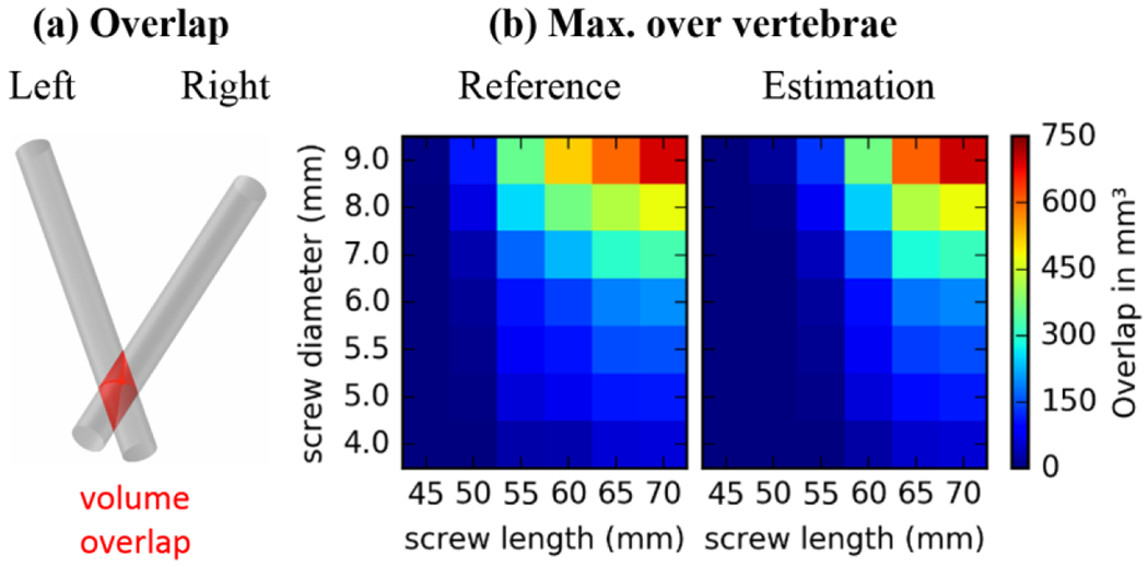
Screw collision: (a) Illustration of the volume overlap displayed in the right subfigures. (b) Maximum collision over all 20 L3 vertebrae showing the worst case at each cell for estimated (right) and reference (left) trajectory.
4. Discussion
Non-rigid registration of a vertebral atlas was shown to be a robust and accurate basis for automatically determining pedicle screw trajectories as well as maximum tolerable screw diameter and length. The median error in surface registration was 0.87 mm for T7/T8 and 1.29 mm for L3, which corresponds to approximately 14% - 19% of the pedicle diameter (Misenhimer et al., 1989). In Misenhimer’s measurements, the median (and range in) outer diameter of the T7, T8, and L3 cortex was 4.7 mm (4.0–5.7 mm), 5.3 mm (3.8–6.9 mm), and 9.2 mm (7.8–10.5 mm), respectively. The surface registration error was similar for T7/T8 and L3 vertebrae despite the different size of the pedicle and vertebral body. On one hand, this may be attributed to the higher density of surface points for a similar number of vertices, and on the other hand, the shape of T7/T8 appears to be less variable among individuals than the shape of L3 and therefore is well suited to registration using a relatively small atlas. More importantly for this work, the accumulation method illustrated in Figure 2a tends to compensate for individual registration errors such that the surface errors do not strongly affect the accuracy of the resulting transpedicle trajectory. This explains to a certain degree why the median trajectory deviation at the T7/T8 pedicle center (0.56 mm) is lower than the median surface registration error (0.87 mm).
The entry point associated with the planned trajectory is an important practical consideration. The results showed that the deviation between the planned and reference entry point was less than 1.4 mm. This suggests that the automatically planned trajectories involve a practical entry point that is surgically accessible (e.g., relative to the joint space, ~5 - 10 mm away). The maximum screw length predicted by the algorithm corresponded closely to that of the expert reference, owing in part to the accuracy in computed trajectory angle (within 3° median deviation from reference).
The maximum diameter also corresponded closely to the expert reference, with the exception of 1–3 outliers likely associated with aggressive purchase of the lateral cortex in the reference data. The L3 left and right trajectories in particular exhibited different performance with respect to maximum non-breaching diameter, owing at least in part to the quality of annotation with respect to the consistency of shape. As evident in Figure 5(b–c, left columns), a difference in consistency of annotation can be seen in the posterior region, reducing the reliability of the L3 left registration. The pose optimization / accumulation step of section 2.3 accommodates such variations to a large extent, evident in the degree of deformation along the trajectory. Not surprisingly, the pose optimization was most important in estimating the trajectory for the L3 left vertebra. Thus, the pose optimization / accumulation step is most important in cases of greater variation in shape or annotation. In order to avoid local minima in this optimization step, the accumulation map should show a single elevation without branches. The accumulation map itself is a direct result of the surface registration and the structure of the expert annotations. It is therefore important that trajectories follow a consistent geometric rule regarding the vertebra shape guided by clinical expertise, to ensure that the cylinder volumes are guaranteed to accumulate properly.
In Figure 7, exemplary trajectory estimations are overlaid on CT image data and input surfaces, showing high correspondence with the expert reference. Accessible entry points, sufficient pedicle space for the screw diameter (5 mm for T7/T8 and 6 mm for L3), and maximal screw length are visible in the CT overlays of Figures 8(a-c) for transverse, coronal, and sagittal slices through the pedicle. Figures 8(d,e) show the corresponding vertebra surface with a comparison of the estimated trajectory (color-coded in yellow) to the reference (color-coded in blue), demonstrating a high similarity.
Figure 7.

Example results. Trajectory plan overlaid on CT: (a) transverse, (b) sagittal, and (c) coronal. Vertebra surface with estimated (blue) and reference trajectory (yellow): (a) axial, and (e) sagittal. A T7/T8 case is shown in the top row, and a L3 case is shown at the bottom.
The atlas underlying the method includes (“reference”) transpedicle trajectories that could be formulated in a variety of ways. For example, the reference trajectories could represent an individual surgeon’s preference and experience. Alternatively, they could reflect consensus agreement of multiple surgeons and related specialists (e.g., neuroradiologists). Furthermore, the reference trajectories could represent biomechanically “optimal” trajectories computed with input from mechanical modeling of each vertebra in the atlas with respect to the anticipated spinal construct. Note that while the atlas does not specify the concept of a “pedicle” (specifying only the vertebrae surfaces and reference trajectory therein), it implicitly incorporates the importance of geometry local to the pedicle via the statistical accumulation of cylindrical trajectories within that region – c.f., the anterior tip of the screw within the vertebral body, where greater variation is tolerable. A benefit of this generic method of definition is the ability to accommodate alternative trajectory techniques as the “reference” – e.g., purposely breaching the lateral pedicle for increased purchase of cortical bone or using two very long bilateral (non-colliding) screws at positive and negative angle of attack for increased purchase within the vertebral body.
The atlas involves vertebrae segmentations that can be defined offline - i.e., with the benefit of time for meticulous manual / semi-automatic definition – and can be expanded to include additional atlas members as desired. The (patient-specific) vertebrae (as depicted in preoperative CT or MRI) must also be segmented. However, the planning method does not depend on a specific segmentation method; rather, any method that provides a reasonable segmentation can be used – for example, recent methods for CT reported in (Castro-Mateos et al., 2015), (Ibragimov et al., 2015), (Ma and Lu, 2013), (Korez et al., 2015), (Rasoulian et al., 2013), (Seitel et al., 2015), (Klinder et al., 2009) and for MRI reported in (Kadoury et al., 2013). Although detection and segmentation of vertebral bodies and discs in MRI is a well-covered area of research (Huang et al., 2009), (Shi et al., 2007), methods for automatic segmentation of CT images are more prevalent in also including the pedicles, which are important for pedicle trajectory estimation. Given such segmentation, the patient-specific pedicle trajectory is then derived from the nonrigid surface registration using the proposed method. Recognizing segmentation to carry additional workflow, ongoing and future work involves adapting the method to register the surface atlas directly to the (segmentation-free) patient image using concepts presented in (Castro-Mateos et al., 2015), (Rasoulian et al., 2013), (Seitel et al., 2015). Moreover, the ability to register the atlas directly within intra-operative time constraints, as demonstrated in (Görres et al., 2016) for calcaneus surfaces, would allow planning of pedicle trajectories based on intraoperative imaging like CBCT or a calibrated set of x-ray images.
Spine surgery carries steep workflow demands, and time consuming processes are unlikely to find broad utilization. Manual delineation of linear transpedicle trajectories in preoperative CT or MRI, for example – while requiring as little as “two clicks” per trajectory – is not consistent with typical workflow, recognizing that 3D visualization tools streamlined to this particular task would be very valuable. Similarly, placement of “virtual screws” using a surgical navigation system requires the surgeon to step physically through each pedicle with a tracked tool and finds limited widespread use. The proposed method is potentially automatic, recognizing that automatic segmentation (by example methods referenced above) requires further validation. Overall, the method is consistent with spine surgery workflow, namely: the atlas of surfaces and transpedicle trajectories is pre-existing; the patient receives pre-operative CT or MRI; the target vertebrae are segmented in the preoperative image (alternatively avoiding this step via surface-to-image registration); the atlas surfaces are registered to the patient image data; and patient-specific trajectories (transformed by the same registrations and accumulated as described above) are available to be loaded along with patient images for purposes of navigation. While the process for atlas-based planning is in many respects automatic and could support streamlined surgical planning, considering the highly delicate surgical task, use of the method should certainly be accompanied by expert supervision and confirmation by the operating surgeon. In particular, the anatomical shape representation resulting from the non-rigid surface-to-surface registration and the trajectory estimation resulting from the rigid image-based registration should be validated by the surgeon with respect to the pre-operative CT or MRI. Computation time is less critical in the context of preoperative planning, since such workflow proceeds outside the operating room hours or days prior to surgery. Provided a segmentation of the target anatomy, the current prototype implementation requires ~10 minutes to create pedicle plans, which is likely compatible with a variety of realistic workflow scenarios.
Automatic planning of pedicle trajectories will allow faster integration of surgical navigation by replacing time-consuming manual planning, automatic intra-operative QA to warn the surgeon in case of deviation from the plan to prevent revision surgeries, and post-operative QA for long-term studies that will help to further elucidate the relation between geometric construct and surgical outcome. For example, recent work combining 3D-2D registration with mobile fluoroscopy can be used for 3D localization of implant devices (Uneri et al., 2015) (Görres et al., 2014), and the measured location can be compared to the planned trajectory as a form of intraoperative QA. Such capability would allow detection of suboptimal screw placement in the OR and immediate revision if warranted, thereby helping to improve surgical outcome and reduce the need for revision surgery.
The patient is described by the deformed atlas, providing an individual vertebra shape. Despite safe and reliable surgical outcome using only geometric concepts based on the vertebra shape (Parker et al., 2011), there are many more patient-specific clinical factors, which might contribute to better surgical outcome. For example, biomechanical properties or the bone density (Knez et al., 2016) are potentially useful to optimize stability of the surgical construct. Combining the current method with additional information, e.g., during the accumulation map creation, is certainly possible and of interest for future work. The method draws from an atlas of nominally “normal” vertebral shapes and therefore may be limited in application to dramatically deformed, degenerated, or fractured vertebral bodies. Future work includes investigation of registration to abnormal target shape, hypothesizing that the solution in the region of the pedicle may be sufficiently constrained and accurate, analogous to the effect observed above with L3 (left), where high variability in shape did not significantly perturb the accuracy of the transpedicle trajectory. Even in the case of strongly deformed vertebrae (e.g., compression fracture), the method may be useful, since the target vertebrae are often the adjacent vertebrae (rather than fractured vertebrae) for placement of screws and rods for fixation.
Furthermore, the method is extensible to automatic planning in other anatomical contexts – e.g., the pelvis, femur, tibia, cranium, etc. – for which an atlas reflecting reliable “reference trajectories” can be defined. Treatment of pelvis trauma, for example, involves a set of fairly well defined trajectories in bone corridors that may be modeled using this approach. Common pelvic trajectories, include the superior pubic ramus (Routt et al., 1995), the anterior inferior iliac spine (AIIS) to posterior superior iliac spine (PSIS) (Schildhauer et al., 2002), and the iliosacral screw going through either S1 or S2 (Routt et al., 1993). Previous work has resulted in pelvic atlases well suited to 3D-2D registration (Yao and Taylor, 2003), (Chintalapani et al., 2007), (Ehlke et al., 2013), and (Zheng et al., 2009). Application of such atlases to our method for automatic planning simply requires the annotation of reference trajectories within each atlas member. We also anticipate application in the calcaneus, where the biomechanically important sustentaculum tali screw (Pang et al., 2014) is placed into protruding bone structure, which carries vulnerable joint surfaces.
5. Conclusion
We have developed an automatic method for pedicle screw trajectory planning based on deformable atlas registration for a given vertebra shape of known level. The method accurately calculates the transpedicle trajectory that provides a close match to expert reference trajectories defined in a manner consistent with the knowledge and experience of good practice. By integrating this method into clinical workflow, we anticipate that the method could streamline intraoperative guidance and quality assurance in spine surgery.
Acknowledgments:
This research was supported by NIH grant R01-EB-017226, and academic industry partnership with Siemens Healthcare (XP Division, Erlangen Germany)
Footnotes
References:
- Attar A, Ugur HC, Uz A, Tekdemir I, Egemen N, Genc Y, 2001. Lumbar pedicle: surgical anatomic evaluation and relationships. Eur. Spine J 10, 10–15. [DOI] [PMC free article] [PubMed] [Google Scholar]
- Castro-Mateos I, Pozo JM, Pereanez M, Lekadir K, Lazary A, Frangi AF, 2015. Statistical Interspace Models (SIMs): Application to Robust 3D Spine Segmentation. IEEE Trans. Med. Imaging 34, 1663–1675. [DOI] [PubMed] [Google Scholar]
- Chintalapani G, Ellingsen LM, Sadowsky O, Prince JL, Taylor RH, 2007. Statistical Atlases of Bone Anatomy: Construction, Iterative Improvement and Validation, in: Ayache N, Ourselin S, Maeder A (Eds.), Medical Image Computing and Computer-Assisted Intervention – MICCAI 2007, Lecture Notes in Computer Science. Springer Berlin; Heidelberg, pp. 499–506. [DOI] [PubMed] [Google Scholar]
- Daemi N, Ahmadian A, Mirbagheri A, Ahmadian AH, Saberi H, Amidi F, Alirezaie J, 2015. Planning screw insertion trajectory in lumbar spinal fusion using pre-operative CT images, in: 2015 37th Annual International Conference of the IEEE Engineering in Medicine and Biology Society (EMBC). pp. 3639–3642. [DOI] [PubMed] [Google Scholar]
- Ehlke M, Ramm H, Lamecker H, Hege H-C, Zachow S, 2013. Fast Generation of Virtual X-ray Images for Reconstruction of 3D Anatomy. IEEE Trans. Vis. Comput. Graph 19, 2673–2682. [DOI] [PubMed] [Google Scholar]
- Görres J, Brehler M, Franke J, Barth K, Vetter SY, Córdova A, Grützner PA, Meinzer H-P, Wolf I, Nabers D, 2014. Intraoperative detection and localization of cylindrical implants in cone-beam CT image data. Int. J. Comput. Assist. Radiol. Surg 9, 1045–1057. [DOI] [PubMed] [Google Scholar]
- Görres J, Brehler M, Franke J, Vetter SY, Grützner PA, Meinzer H-P, Wolf I, 2016. Articular surface segmentation using active shape models for intraoperative implant assessment. Int. J. Comput. Assist. Radiol. Surg 11, 1661–1672. [DOI] [PubMed] [Google Scholar]
- Huang SH, Chu YH, Lai SH, Novak CL, 2009. Learning-Based Vertebra Detection and Iterative Normalized-Cut Segmentation for Spinal MRI. IEEE Trans. Med. Imaging 28, 1595–1605. [DOI] [PubMed] [Google Scholar]
- Ibragimov B, Korez R, Likar B, Pernuš F, Vrtovec T, 2015. Interpolation-Based Detection of Lumbar Vertebrae in CT Spine Images. Recent Adv. Comput. Methods Clin. Appl. Spine Imaging, Lecture Notes in Computational Vision and Biomechanics 73–84. [Google Scholar]
- Ibragimov B, Likar B, Pernus F, Vrtovec T, 2014. Shape Representation for Efficient Landmark-Based Segmentation in 3-D. IEEE Trans. Med. Imaging 33, 861–874. [DOI] [PubMed] [Google Scholar]
- Ju T, Schaefer S, Warren J, 2005. Mean Value Coordinates for Closed Triangular Meshes, in: ACM SIGGRAPH 2005 Papers, SIGGRAPH ’05. ACM, pp. 561–566. [Google Scholar]
- Kadoury S, Labelle H, Paragios N, 2013. Spine Segmentation in Medical Images Using Manifold Embeddings and Higher-Order MRFs. IEEE Trans. Med. Imaging 32, 1227–1238. [DOI] [PubMed] [Google Scholar]
- Klinder T, Ostermann J, Ehm M, Franz A, Kneser R, Lorenz C, 2009. Automated model-based vertebra detection, identification, and segmentation in CT images. Med. Image Anal 13, 471–482. [DOI] [PubMed] [Google Scholar]
- Knez D, Likar B, Pernuš F, Vrtovec T, 2016. Computer-Assisted Screw Size and Insertion Trajectory Planning for Pedicle Screw Placement Surgery. IEEE Trans. Med. Imaging 35, 1420–1430. [DOI] [PubMed] [Google Scholar]
- Korez R, Ibragimov B, Likar B, Pernuš F, Vrtovec T, 2015. A Framework for Automated Spine and Vertebrae Interpolation-Based Detection and Model-Based Segmentation. IEEE Trans. Med. Imaging 34, 1649–1662. [DOI] [PubMed] [Google Scholar]
- Kosmopoulos V, Schizas C, 2007. Pedicle Screw Placement Accuracy: A Meta-analysis. Spine 32, E111–E120. [DOI] [PubMed] [Google Scholar]
- Lee J, Kim S, Kim YS, Chung WK, 2012. Optimal surgical planning guidance for lumbar spinal fusion considering operational safety and vertebra–screw interface strength. Int. J. Med. Robot 8, 261–272. [DOI] [PubMed] [Google Scholar]
- Lonstein JE, Denis F, Perra JH, Pinto MR, Smith MD, Winter RB, 1999. Complications Associated with Pedicle Screws*. J Bone Jt. Surg Am 81, 1519–28. [DOI] [PubMed] [Google Scholar]
- Ma J, Lu L, 2013. Hierarchical segmentation and identification of thoracic vertebra using learning-based edge detection and coarse-to-fine deformable model. Comput. Vis. Image Underst 117, 1072–1083. [DOI] [PubMed] [Google Scholar]
- Misenhimer GR, Peek RD, Wiltse LL, Rothman SLG, Widell EHJ, 1989. Anatomic Analysis of Pedicle Cortical and Cancellous Diameter as Related to Screw Size. Spine 14, 367–372. [DOI] [PubMed] [Google Scholar]
- Myronenko A, Song X, 2010. Point Set Registration: Coherent Point Drift. IEEE Trans. Pattern Anal. Mach. Intell 32, 2262–2275. [DOI] [PubMed] [Google Scholar]
- Pang Q-J, Yu X, Guo Z-H, 2014. The sustentaculum tali screw fixation for the treatment of Sanders type II calcaneal fracture: A finite element analysis. Pak. J. Med. Sci 30, 1099–1103. [DOI] [PMC free article] [PubMed] [Google Scholar]
- Parker SL, McGirt MJ, Farber SH, Amin AG, Rick A-M, Suk I, Bydon A, Sciubba DM, Wolinsky J-P, Gokaslan ZL, Witham TF, 2011. Accuracy of free-hand pedicle screws in the thoracic and lumbar spine: analysis of 6816 consecutive screws. Neurosurgery 68, 170–178; discussion 178. [DOI] [PubMed] [Google Scholar]
- Pauwels R, Jacobs R, Bosmans H, Pittayapat P, Kosalagood P, Silkosessak O, Panmekiate S, 2013. Automated implant segmentation in cone-beam CT using edge detection and particle counting. Int. J. Comput. Assist. Radiol. Surg 9, 733–743. [DOI] [PubMed] [Google Scholar]
- Peters TM, 2006. Image-guidance for surgical procedures. Phys. Med. Biol 51, R505. [DOI] [PubMed] [Google Scholar]
- Rasoulian A, Rohling R, Abolmaesumi P, 2013. Lumbar Spine Segmentation Using a Statistical Multi-Vertebrae Anatomical Shape+Pose Model. IEEE Trans. Med. Imaging 32, 1890–1900. [DOI] [PubMed] [Google Scholar]
- Ritschl L, Kuntz J, Fleischmann C, Kachclrieß M, 2016. The rotate-plus-shift C-arm trajectory. Part I. Complete data with less than 180° rotation. Med. Phys 43, 2295–2302. [DOI] [PubMed] [Google Scholar]
- Routt MLCJ, Meier MC, Kregor PJ, Mayo KA, 1993. Percutaneous iliosacral screws with the patient supine technique. Oper. Tech. Orthop 3, 35–45. [Google Scholar]
- Routt MLCJ, Simonian PT, Grujic L, 1995. Preliminary Report: The Retrograde Medullary Superior Pubic Ramus Screw for the Treatment of Anterior Pelvic Ring Disruptions: A New Technique. J. Orthop. Trauma 9, 35–44. [DOI] [PubMed] [Google Scholar]
- Schafer S, Nithiananthan S, Mirota DJ, Uneri A, Stayman JW, Zbijewski W, Schmidgunst C, Kleinszig G, Khanna AJ, Siewerdsen JH, 2011. Mobile C-arm cone-beam CT for guidance of spine surgery: Image quality, radiation dose, and integration with interventional guidance. Med. Phys 38, 4563–4574. [DOI] [PMC free article] [PubMed] [Google Scholar]
- Schildhauer TA, McCulloch P, Chapman JR, Mann FA, 2002. Anatomic and Radiographic Considerations for Placement of Transiliac Screws in Lumbopelvic Fixations. J. Spinal Disord 15,199–205. [DOI] [PubMed] [Google Scholar]
- Seitel A, Rasoulian A, Rohling R, Abolmaesumi P, 2015. Lumbar and Thoracic Spine Segmentation Using a Statistical Multi-object Shape+Pose Model, in: Yao J, Glocker B, Klinder T, Li S (Eds.), Recent Advances in Computational Methods and Clinical Applications for Spine Imaging, Lecture Notes in Computational Vision and Biomechanics. Springer International Publishing, pp. 221–225. [Google Scholar]
- Shi R, Sun D, Qiu Z, Weiss KL, 2007. An Efficient Method for Segmentation of MRI Spine Images, in: 2007 IEEE/ICME International Conference on Complex Medical Engineering, pp. 713–717. [Google Scholar]
- Siewerdsen JH, Moseley DJ, Burch S, Bisland SK, Bogaards A, Wilson BC, Jaffray DA, 2005. Volume CT with a flat-panel detector on a mobile, isocentric C-arm: Pre-clinical investigation in guidance of minimally invasive surgery. Med. Phys 32, 241–254. [DOI] [PubMed] [Google Scholar]
- Silbermann J, Riese F, Allam Y, Reichert T, Koeppert H, Gutberlet M, 2011. Computer tomography assessment of pedicle screw placement in lumbar and sacral spine: comparison between free-hand and O-arm based navigation techniques. Eur. Spine J 20, 875–881. [DOI] [PMC free article] [PubMed] [Google Scholar]
- Solitro GF, Amirouche F, 2016. Innovative approach in the development of computer assisted algorithm for spine pedicle screw placement. Med. Eng. Phys 38, 354–365. [DOI] [PubMed] [Google Scholar]
- Uneri A, Silva TD, Stayman JW, Kleinszig G, Vogt S, Khanna AJ, Gokaslan ZL, Wolinsky J-P, Siewerdsen JH, 2015. Known-component 3D–2D registration for quality assurance of spine surgery pedicle screw placement. Phys. Med. Biol 60, 8007. [DOI] [PMC free article] [PubMed] [Google Scholar]
- Valette S, Chassery J-M, 2004. Approximated Centroidal Voronoi Diagrams for Uniform Polygonal Mesh Coarsening. Comput. Graph. Forum 23, 381–389. [Google Scholar]
- Watkins RG, Gupta A, Watkins RG, 2010. Cost-Effectiveness of Image-Guided Spine Surgery. Open Orthop. J 4, 228–233. [DOI] [PMC free article] [PubMed] [Google Scholar]
- Weiss AJ, Elixhauser A, Andrews RM, 2014. Characteristics of Operating Room Procedures in U.S. Hospitals, 2011 (Internet No. 170), Healthcare Cost and Utilization Project (HCUP) Statistical Briefs. [Google Scholar]
- Wicker R, Tedla B, 2004. Automatic determination of pedicle screw size, length, and trajectory from patient data, in: 26th Annual International Conference of the IEEE Engineering in Medicine and Biology Society, 2004. IEMBS ’04. pp. 1487–1490. [DOI] [PubMed] [Google Scholar]
- Yao J, Burns JE, Forsberg D, Seitel A, Rasoulian A, Abolmaesumi P, Hammernik K, Urschler M, Ibragimov B, Korez R, Vrtovec T, Castro-Mateos I, Pozo JM, Frangi AF, Summers RM, Li S, 2016. A multi-center milestone study of clinical vertebral CT segmentation. Comput. Med. Imaging Graph 49, 16–28. [DOI] [PMC free article] [PubMed] [Google Scholar]
- Yao J, Burns JE, Munoz H, Summers RM, 2012. Detection of Vertebral Body Fractures Based on Cortical Shell Unwrapping, in: Medical Image Computing and Computer-Assisted Intervention – MICCAI 2012. pp. 509–516. [DOI] [PMC free article] [PubMed] [Google Scholar]
- Yao J, Taylor R, 2003. Assessing accuracy factors in deformable 2D/3D medical image registration using a statistical pelvis model, in: Ninth IEEE International Conference on Computer Vision, pp. 1329–1334 vol. 2. [Google Scholar]
- Zhang J, Weir V, Fajardo L, Lin J, Hsiung H, Ritenour ER, 2009. Dosimetric characterization of a cone-beam O-arm™ imaging system. J. X-Ray Sci. Technol 17, 305–317. [DOI] [PubMed] [Google Scholar]
- Zheng G, Zhang X, Steppacher SD, Murphy SB, Siebenrock KA, Tannast M, 2009. HipMatch: An object-oriented cross-platform program for accurate determination of cup orientation using 2D–3D registration of single standard X-ray radiograph and a CT volume. Comput. Methods Programs Biomed 95, 236–248. [DOI] [PubMed] [Google Scholar]