Abstract
Bioprinting is an emerging multidisciplinary technology for organ manufacturing, tissue repair, and drug screening. The manufacture of organs in a layer-by-layer manner is a characteristic of bioprinting technology, which can also determine the accuracy of constructs confined by the printing resolution. The lack of sufficient resolution will result in defect generation during the printing process and the inability to complete the manufacture of complex organs. A computer vision-based method is proposed in this study to detect the deviation of the printed helix from the reference trajectory and calculate the modified reference trajectory through error vector compensation. The new printing helix trajectory resulting from the modified reference trajectory error is significantly reduced compared with the original helix trajectory and the correction efficiency exceeded 90%.
Keywords: Bioprinting, Computer vision, Error detection, Quality assurance, Sobel operator
1. Introduction
As a novel and advanced method, bioprinting is developed based on additive manufacturing technologies and has attracted significant attention from academia and the medical sector since it may deliver a promising solution to the shortage of organ for transplantation[1-3]. Although artificial human heart was successfully produced by bioprinting technology, systematic investigations of organ bioprinting are still rare, especially on the integrity of organ and tissue regeneration[4]. Hence, the utilization of artificial bioprinted organs is still in its infancy and facing tremendous challenges[5].
At present, bioprinting is divided into extrusion-based, injection-based, droplet, and stereolithography bioprinting[6-8]. Extrusion-based bioprinting is the most popular bioprinting method with much higher efficiency than other bioprinting methods since it can support large-volume printing structures[9,10]. The power sources of extrusion-based bioprinting can be categorized into three types, that is, air pressure, rotation, and force, as shown in Figure 1A. These external forces push the bioink in the pipeline then the bioink is extruded from the extrusion nozzle in a layer-by-layer manner, according to a predetermined trajectory and the organ manufacturing model.
Figure 1.
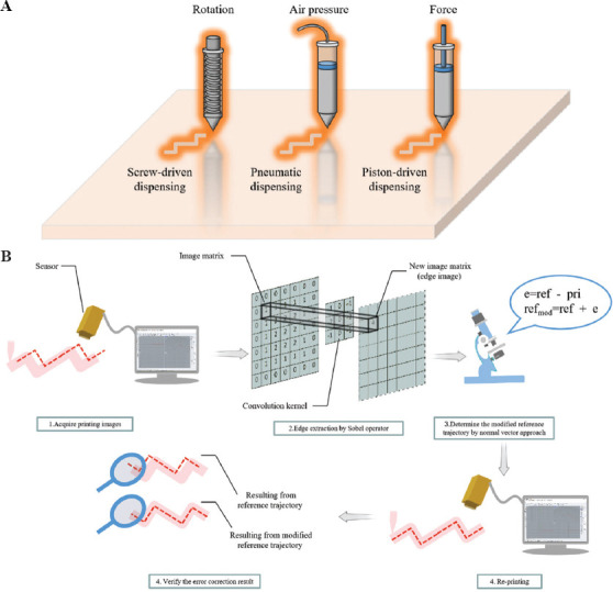
(A) Three sources of bioprinting power. From left to right: Rotation dispensing by screw driven, air pressure dispensing by pneumatic, and force dispensing by piston driven. (B) Schematic illustration of computer vision-aided trajectory error assessment and correction in bioprinting.
Despite the numerous advantages of bioprinting, low printing resolution is a critical issue limiting bioprinting development and utilization. It should be noted that bioprinting resolution is a decisive factor affecting the overall quality of printing[11,12]. A lower resolution substantially reduces the accuracy in the bioprinting model, thereby resulting in tremendous hidden dangers which affect treatment procedure and the overall success of organ transplantation. For instance, studies have shown that the survival rate and differentiation of osteoblasts in the lattice area are higher than those in the film area in the bioprinting experiment. In the same printing environment, the low printing resolution leads to fading and the blur between the lattice area and the film area that finally will induce ambiguity and problems in the final cell survival rate and classification status[13]. Furthermore, recent studies on the bioprinting of the human heart have indicated that the resolution of utilized bioprinting technology has a significant impact on the formation of blood vessels in the heart[4].
Poor process control and feedback during the printing by extrusion-based bioprinting devices is the principal factor of the low resolution of extrusion-based bioprinting, which is a primary limitation of this printing process[14]. The actual printing trajectory often does not reflect according to the originally designed reference trajectories, and some error remains between the designed reference trajectories. The deviation error between the actual trajectory and the reference trajectory is small during the straight-line printing scheme, while the deviation error significantly increases during the printing process of bending and curving structures[15,16].
Many organ bioprinting models, including ear bioprinting model, have been proposed in recent studies[17,18]. The ear is a typical three-dimensional (3D) organ with a curved structure. A computer vision system was never used to achieve process control in most of the studies, which means the error between the actual printing trajectory and the reference trajectory during the printing process remains and affects the final product, reducing the resolution of ears[19].
The main objective of this research is to reduce the deviation error between the printing helix trajectory and the reference trajectory to improve the printing resolution, as shown in Figure 1B. A process control method is proposed based on computer vision to locate the helix coordinates and ensure that the helix is extruded at the correct position. The central concept of computer vision is to use equipment and algorithm to replace the human eye to identify objects and obtain information to achieve exact object positioning, object size measurement, and defect detection[20-22]. The deviation error is difficult to distinguish by the naked eye but could be effectively detected and visualized by computer vision. The collected deviation error plays an important role in modifying the reference trajectory to readjust the position of the helix printing. Improved computer vision strategies are required to ensure that the printed structures are of high shape complexity and to improve extrusion bioprinting.
2. Method
2.1. System parameters and material design
A non-contact camera (Samsung SM-G7810) is placed above the XY printing plane to take helix images. The original helix image data are abstract and cannot be directly used for error calculation, so the helix images must be preprocessed by image algorithms. The content of the algorithm will be discussed in sections 2.3 and 2.4.
Alginate-based hydrogel is used as the bioink material for helix printing. The core component of the alginate-based hydrogel, alginate, is a derivative of alginic acid, which has the structure of long chains of polysaccharides to maintain the state of the gel[23-26]. At present, alginate-based hydrogels are still among the mainstream substances for biological tissue engineering, including drug delivery[27], vaccine manufacturing[28], tissue regeneration[29], and bioprinting[30].
2.2. Printing helix number
To verify the universality of the proposed computer vision-based process control method, three helixes with different sizes and trajectories were put into the printing and correction system. The printing error produced by each helix will show different fluctuations degrees during the bioprinting process due to the difference in the size and curvature degree of the helix. These helix structures are designed by computer-aided design software as a printing helix reference trajectory composed of various straight and curved lines.
2.3. Process control
Process control of bioprinting is proposed to detect and reduce the possible errors between the ideal reference trajectory and the actual printing trajectory that remains in the printed helix. The overall process control can be divided into a measurement part and an execution part; these two parts are shown in Figure 2A. The purpose of the measurement part is to determine the error between the actual printing trajectory and the ideal reference trajectory. Next, the error correction and verification procedure will be accomplished in the execution part. MATLAB was used to calculate the deviation value between two trajectories and to obtain the new reference trajectory.
Figure 2.
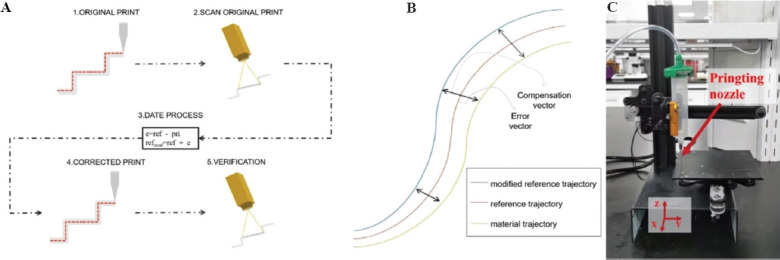
Schematic illustration of the process control principle for helix trajectory detection and correction. (A) Five steps from process control to identification and correction of helix trajectory. (B) Example of normal vector approach to compensate the error vector of the reference trajectory by mirroring to obtain a new modified reference trajectory. (C) Extrusion-based bioprinting machine with standard Cartesian coordinates.
The first step of the procedure is the original bioprinting part. The extrusion-based bioprinting machine performs printing according to the original helix reference trajectory. There is no correction operation added in this step, and the error between the printed helix trajectory and the ideal reference trajectory is retained in the final helix. The second step uses a camera to take the printed helix images. The camera is horizontally fixed to the top of the printed helix and takes the entire helix trajectory images after bioprinting is finished. The captured helix images are required to be preprocessed to acquire the point cloud data; then, the point cloud data will be transmitted to the Cartesian coordinate system to facilitate the subsequent error calculations. The third step is error calculation which is the most critical part. The different vector between the actual printing helix trajectory and the reference trajectory is defined as the error value. The normal vector approach, as shown in Figure 2B, uses the compensation vector calculated by the error vector to obtain a new corrected reference path. First, the algorithm determines the size of the compensation vector based on the error and then compensates the original reference trajectory by mirroring to obtain a new reference trajectory[31]. The fourth step is a correction step. The new printing helix trajectory will be guided with the corrected reference trajectory of the replenishment vector obtained in the previous step. The fifth step is the verification step. The specific operation is the same as the second step, in which the new helix trajectory is put into the Cartesian coordinate system to detect the error value compared with the ideal reference trajectory.
2.4. Image algorithm
Figure 3A-G shows the steps in detail to transform abstract helix image data into coordinate data by the algorithm. Furthermore, the error between the helix and the reference trajectory is calculated based on the coordinate data of the helix; accordingly, the modification of the reference trajectory is proposed.
Figure 3.
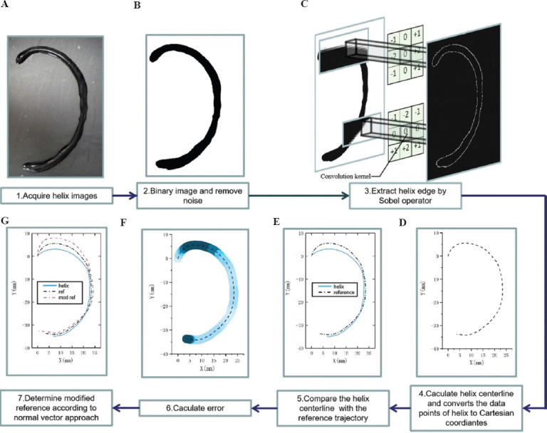
(A-G) The input data required for trajectory correction and seven different processing steps for the helix image. The captured helix trajectory photos cannot be directly calculated by the trajectory error since the image data are unacceptable for the error algorithm. The coordinate data converted from the image data by binarization and edge extraction processing is used for comparison with the reference trajectory, and calculation of the deviation value of the helix trajectory.
At first, the original images of the printed helix trajectory are collected. Then, the collected images are binarized to reduce the 3D image channel of the picture into the single channel. The purpose is to strengthen the contour edge feature of the image and facilitate subsequent image processing. In the third step, the edges of the binarized helix are identified and extracted by the Sobel operator, as shown in Figure 3C, to convert the abstract image data into specific point cloud data. Object contour recognition is an emerging field of computer vision to visualize algorithms to recognize the contours of objects to quickly determine the type of objects. The convolution kernel is used to process the image matrix. Which is the most popular object contour recognition algorithm[32–35]. Two 3×3 convolution kernels are shown in Figure 4. Each pixel in the image matrix is convolved by the convolution kernel. The convolution kernels on the left and right in Figure 4 have a maximum response to the vertical edge and level edge, respectively. The helix edge is obtained according to the maximum value of the two convolution kernels.
Figure 4.
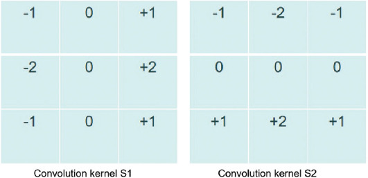
Sobel edge operator
In the fourth step, the centerline estimate of the helix is calculated based on the helix contour. The centerline of the helix is defined as the helix trajectory after the bioprinting and is placed in the Cartesian coordinate system for subsequent error calculations. In the fifth step, the print helix trajectory in the Cartesian coordinate system (blue solid line) deviates from the predetermined reference trajectory (black dashed line). Figure 3E records the print trajectory and reference trajectory of the helix in the same Cartesian coordinate system. In the sixth step, due to the offset of the helix print trajectory (blue solid line) in the Cartesian coordinate system, the difference between each point of the helix trajectory and the reference trajectory could be calculated. Figure 3F illustrates the error generation in each of the trajectory segments. In the seventh step, the new reference trajectory is obtained by compensating the error vector, on the foundation of the reference trajectory.
3. Results
3.1. Original printing
The point cloud data of the printing helix trajectory after bioprinting were collected according to the algorithm introduced in Section 2.4. The printing trajectory and the reference trajectory were both established in the same Cartesian coordinate system. Figure 5 shows the printed helix trajectory (solid flesh-colored line), the estimated value of the printing helix centerline (red dotted line), and the designed ideal reference trajectory (black dotted line).
Figure 5.
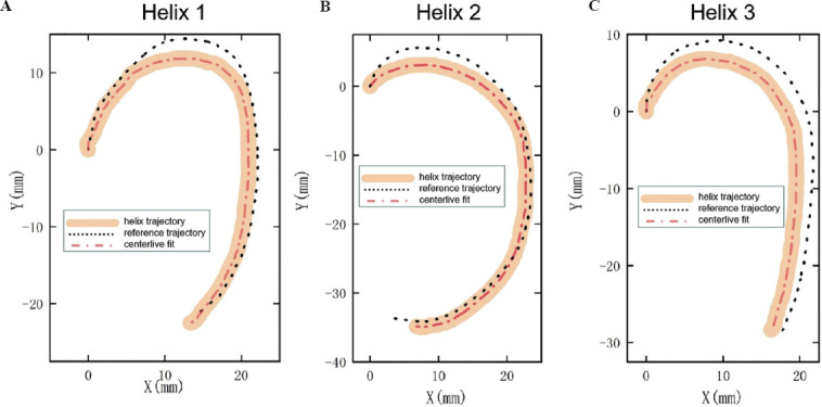
(A-C) The observed solid flesh-colored, black-dashed, and red-dashed lines indicated the print helix locus, reference locus, and the printed helix centerline estimation, respectively. The black-dashed line was the printing helix trajectory obtained in an ideal state, and the red-dashed line output of the algorithm represents the helix printing trajectory.
3.2. Correct printing
The coordinate data of the ideal helix reference trajectory and printing helix trajectory could be collected and counted; then, the modified helix reference trajectory with error vector compensation could be determined through the normal vector approach. Figure 6 shows the XY plane containing the printing helix trajectory resulting from the modified helix reference trajectory and the original printing helix trajectory. The white path was the original helix trajectory, and the translucent blue path was the new printing helix trajectory resulting from modified reference trajectory. The black dashed line was the pre-designed reference trajectory, which was the ideal printing result without error interference.
Figure 6.
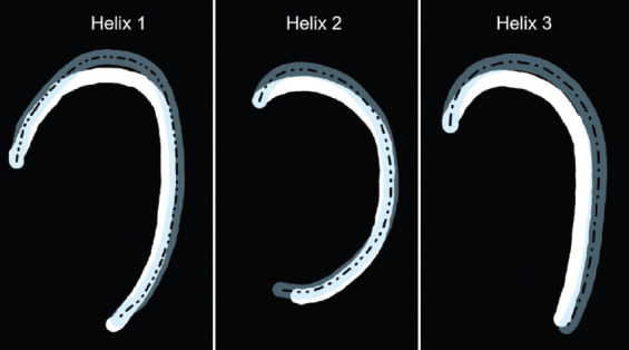
The original printed helix trajectory (white material), the new printed helix trajectory (translucent blue material), and the pre-designed reference trajectory (translucent blue material).
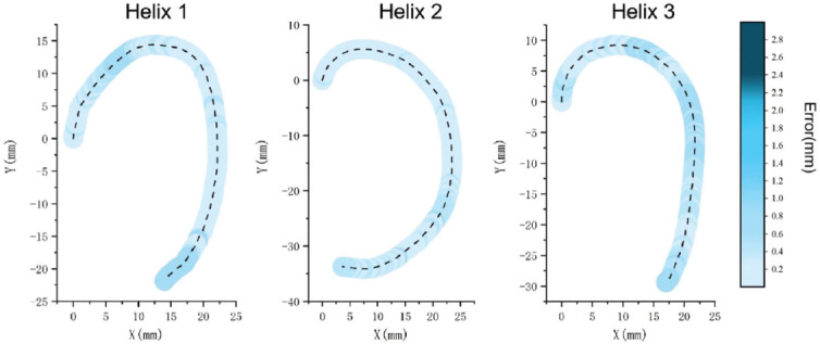
The deviation vector between the original printing helix trajectory and the ideal reference trajectory was defined as the bioprinting error. Figure 7 reveals the error values of different positions for each original helix trajectory in the coordinate system by mapping the error values to the printed helix trajectory. The color depth was carried by the color column placed on the right side of the coordinate system, reflecting the error magnitude of each printing helixes. The error and its degree for each printing helix showed an increasing tendency with the color transitioning from light blue to dark blue. The error exceeded 2.4 mm which the color was between blue and black, reaching the high error range. The dashed line in Figure 7 represents the centerline of the printing helix trajectory, and the different depths of blue color surrounding the centerline represent the error value carried by the helix at different positions, which correspond to the error color column on the right. The dark blue magnitude of error could be seen in the three-helix trajectories, illustrating that the three helixes showed a significant error, exceeding 2.4 mm.
Figure 7.
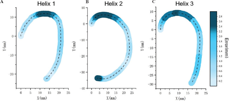
(A-C) The error between the printing helix trajectory and the reference trajectory was mapped to the helix trajectory; the darker blue represents higher level of error. The error value of each helix was shown in the color column on the right. Each helix model was tested 3 times repeatedly.
Figure 8 presents additional data of the normal vector approach for each helix: Corrected reference trajectory and corrected printing helix trajectory. In Figure 8A, the original reference trajectory and the modified reference trajectory of the compensation error were compared. “Orig Ref” was a black-dashed line representing the original reference trajectory, and “Corr Ref” was a blue solid line representing the modified reference trajectory. Figure 8B compared two printing trajectories resulting from the original reference trajectory and the modified reference trajectory. Compared with the original printing, the printed helix trajectory resulting from the modified reference trajectory was overlapped with the ideal helix trajectory as much as possible. “Orig Ref” was a black-dashed line representing the original reference trajectory; “Orig Prt” was a blue solid line representing the printing helix trajectory that resulted from the initial reference trajectory; and “Corr Prt” was the red dashed line representing the printed helix trajectory resulting from the modified reference trajectory.
Figure 8.
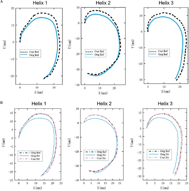
(A) Comparison of the original reference path (blue solid line) and the modified reference path (black-dashed line). (B) Original reference path (black-dashed line), printing helix trajectory resulting from original reference trajectory (blue solid line), and printing helix trajectory resulting from modified reference trajectory (red-dashed line).
The corrected printing helix trajectory stemming from the modified reference trajectory for each helix was collected, and the error between the ideal reference trajectory and printing helix trajectory was counted, as shown in Figure 9. The black-dashed line represented the correct printing helix trajectory, and the surrounding blue line mapped the errors at different positions. The depth of the color reflected the error value between the corrected printing helix trajectory and the ideal reference trajectory. The error value corresponded to the error color column on the right, which was consistent with the color column, as shown in Figure 7. Obviously, the error value of the corrected printing helix trajectory had been reduced dramatically by algorithm processing and a high error range represented by dark blue hues for each helix compared with the original printing helix trajectory was absent.
Figure 9.
The error between the corrected printing helix trajectory and the reference trajectory was mapped to the helix trajectory; the darker blue represents higher level of error. The error value of each helix was shown in the color column on the right.
3.3. Repeatability
To ensure that the error statistics of the corrected helix print trajectory maintained high repeatability, three repeated corrected printing helix trajectories for each helix were tested independently. Figure 10 illustrates the error distribution state in three printings for each helix. The value of the overall error in the low error range (light blue) was less than 1.0 mm, while there was no high error range (dark blue) in the three printing experiments of each helix.
Figure 10.
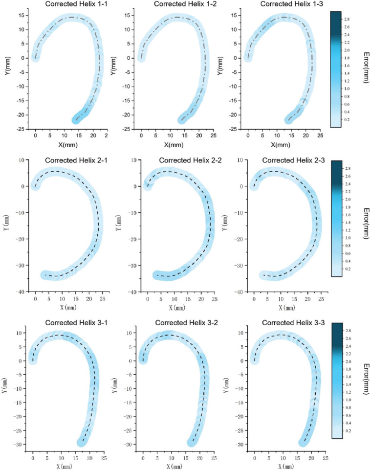
Printing helix trajectory resulting from modified reference trajectory was printed 3 times, and all errors of each helix were located in the low error range (light blue).
4. Discussion
Many studies have indicated that bioprinting resolution is a crucial printing parameter. However, the number of studies aiming to improve printing resolution, including printing error detection and correction, is still limited. Most of the printing helix trajectories contain large curves, which induce much greater challenges in the error correction stage. Figure 5 shows the deviation error between the printed helix trajectory and the ideal reference trajectory. Therefore, the significance of this study is to correct this deviation value and to improve the resolution of extrusion-based bioprinting. The error of each helix reference trajectory is compensated according to the normal vector approach, and the printed helix trajectory is overlapped with the ideal helix trajectory as much as possible. Furthermore, the printing error is reduced to an acceptable range.
Figure 7 shows that the errors are not similar at different positions between the printing helix trajectory and the ideal reference trajectory in the same Cartesian coordinate system. The dark blue area with high error is concentrated on the top curvature position for each helix, which indicates that the error value at the curvature position is higher than the error at the other positions, and the highest error reaches 2.53 mm in the second helix calculated by Euclidean norm (1)[36]. The error level shows a decreasing tendency due to the helix trajectory changes from curve to straight, which dropped to the blue and light blue middle error range. Furthermore, compared with straight trajectory, relying on single-axis control, the curved trajectory requires two axes to control the print head during the printing process, and the error level is also higher than the straight trajectory because of the low accuracy of multiple axis motion.
For the new printing helix trajectory resulting from the modified reference trajectory, the errors are all located in the light blue area with low error and less than 1.0 mm. The errors higher than 1.0 mm are corrected by the algorithm and do not appear in the statistical results for each helix, as shown in Figure 8. Especially, the average error in the dark blue area with high error at the top curvature position calculated by Euclidean norm (1), has dropped from 2.33 mm, 2.34 mm, and 2.15 mm to 0.21 mm, 0.19 mm, 0.28 mm, respectively, and reached to efficiency rates of about 91%, 92%, and 87%, respectively in Table 1. The curve structure error has been greatly reduced, which proves that the normal vector approach algorithm has a strong correction ability in the curve structure.
Table 1.
Error results before and after correction for each helix
| Helix 1 | Helix 2 | Helix 3 | |
|---|---|---|---|
| Average error (mm) | 1.06 | 1.15 | 1.58 |
| Corrected error (mm) | 0.36 | 0.25 | 0.48 |
| Average error (mm) (high error range) | 2.33 | 2.34 | 2.15 |
| Corrected error (mm) (high error range) | 0.21 | 0.19 | 0.25 |

Computer vision technology is applied to the experimental operation to obtain the point cloud data of the printing helix and realize the process control. A non-contact camera is placed directly above the printing platform and records the entire printing of the helix images during the bioprinting process. The recorded helix images will be transferred from the camera to the computer system, the edges of the helix will be identified and extracted by the Sobel operator. The estimated value of the printing helix centerline can be calculated by the edges of the helix, which represents the printing helix trajectory. In the future, computer vision will play an important role in process control with the development of computer science, including more accurate measurement of the printed components’ size. More precise centerline data accurately reflect the printing helix trajectory, and the modified reference trajectory could be exactly expressed by the normal vector approach, which indirectly improves the accuracy of correction.
At present, the position of the printed helix trajectory is adjusted as much as possible to be consistent with the reference trajectory, and the helix error in the two-dimensional (2D) space has been significantly reduced with computer vision processing. In the future work, an extension of the 2D space to the entire 3D space to evaluate and correct the errors of other 3D organs should be attempted. However, the study was afflicted with a few challenges. For example, the current computer vision is beneficial in processing flat images, but in the case of a target object with a 3D image, the limitations of computer vision will be magnified. Furthermore, the error definition will also shift from 2D space to 3D space. Hence, further investigations are required on this topic.
5. Conclusions
The main limitation for high-precision bioprinting is the low resolution caused by the lack of process control, which is reflected in the printing trajectory as a deviation from the original reference trajectory. The error caused by this deviation is one of the reasons that affect the resolution of extrusion-based bioprinting. In this study, computer vision technology was applied to helix bioprinting to achieve process control. The average error of the three helixes has been reduced from 1.06 mm, 1.15 mm, and 1.58 mm to 0.36 mm, 0.25 mm, and 0.48mm, respectively. For the high error area of each helix, the average error has been reduced from 2.33 mm, 2.34 mm, and 2.15 mm to 0.21 mm, 0.19 mm, and 0.25mm, respectively, and the correction efficiency has reached 91%, 92%, and 87%, respectively. The resolution of bioprinting shows a great improvement, it should be noted that only the reference trajectory is modified. More intuitively, the error is significantly reduced compared with the original helix printing trajectory after correction and shows high repeatability.
This study, for the 1st time, proposes the use of a computer vision technology in bioprinting procedure to reduce the deviation values of the printing helix trajectory compared to the reference trajectory through process control. This method is applicable to the printing of other organs, in addition to the human ear, so as to reduce printing errors. Through this procedure, the bioprinting resolution can be further increased and the printing accuracy can be improved, thereby improving the areas of organ manufacturing and tissue engineering.
Acknowledgments
Guangxi Science and Technology Program: The central government guides the local science and technology development science and technology innovation base project (Guike Jizi[2020] No.198): Basic Research and Transformation Technology Innovation Base of Bone and Joint Degenerative Diseases.
Funding
The authors thankfully acknowledge the financial support listed as below: National Natural Science Foundation of China under (Grant Nos.51831011, 52011530181), Shanghai Science and Technology Commission under Grant No.20S31900100.
Conflict of interest
The authors declare no competing financial interests.
Authors’ contributions
The manuscript was written through contributions of all authors. All authors have given approval to the final version of the manuscript.
References
- 1.Lawlor KT, Vanslambrouck JM, Higgins JW, et al. Cellular Extrusion Bioprinting Improves Kidney Organoid Reproducibility and Conformation. Nat Mater. 2021;20:260–71. doi: 10.1038/s41563-020-00853-9. https://doi.org/10.1038/s41563-020-00853-9. [DOI] [PMC free article] [PubMed] [Google Scholar]
- 2.Cui X, Breitenkamp K, Finn MG, et al. Direct Human Cartilage Repair Using Three-Dimensional Bioprinting Technology. Tissue Eng A. 2012;18:1304–12. doi: 10.1089/ten.tea.2011.0543. https://doi.org/10.1089/ten.tea.2011.0543. [DOI] [PMC free article] [PubMed] [Google Scholar]
- 3.Yanez M, Rincon J, Dones A, et al. In Vivo Assessment of Printed Microvasculature in a Bilayer Skin Graft to Treat Full-Thickness Wounds. Tissue Eng A. 2015;21:224–33. doi: 10.1089/ten.tea.2013.0561. https://doi.org/10.1089/ten.tea.2013.0561. [DOI] [PMC free article] [PubMed] [Google Scholar]
- 4.Lee A, Hudson AR, Shiwarski DJ, et al. 3D Bioprinting of Collagen to Rebuild Components of the Human Heart. Science. 2019;365:482–7. doi: 10.1126/science.aav9051. https://doi.org/10.1126/science.aav9051. [DOI] [PubMed] [Google Scholar]
- 5.Daly AC, Prendergast ME, Hughes AJ, et al. Bioprinting for the Biologist. Cell. 2021;184:18–32. doi: 10.1016/j.cell.2020.12.002. https://doi.org/10.1016/j.cell.2020.12.002. [DOI] [PMC free article] [PubMed] [Google Scholar]
- 6.Jose RR, Rodriguez MJ, Dixon TA, et al. Evolution of Bioinks and Additive Manufacturing Technologies for 3D Bioprinting. ACS Biomater Sci Eng. 2016;2:1662–78. doi: 10.1021/acsbiomaterials.6b00088. https://doi.org/10.1021/acsbiomaterials.6b00088. [DOI] [PubMed] [Google Scholar]
- 7.Murphy SV, Atala A. 3D Bioprinting of Tissues and Organs. Nat Biotechnol. 2014;32:773–85. doi: 10.1038/nbt.2958. https://doi.org/10.1038/nbt.2958. [DOI] [PubMed] [Google Scholar]
- 8.Zorlutuna P, Jeong JH, Kong H, et al. Stereolithography-Based Hydrogel Microenvironments to Examine Cellular Interactions. Adv Funct Mater. 2011;21:3642–51. https://doi.org/10.1002/adfm.201101023. [Google Scholar]
- 9.Darwish LR, El-Wakad MT, Farag MM. Towards an Ultra-Affordable Three-Dimensional Bioprinter:A Heated Inductive-Enabled Syringe Pump Extrusion Multifunction Module for Open-Source Fused Deposition Modeling Three-Dimensional Printers. J Manuf Sci Eng. 2021;143:125001. https://doi.org/10.1115/1.4050824. [Google Scholar]
- 10.Duan B, Hockaday LA, Kang KH, et al. 3D Bioprinting of Heterogeneous Aortic Valve Conduits with Alginate/Gelatin Hydrogels. Bone. 2008;23:1–7. doi: 10.1002/jbm.a.34420. https://doi.org/10.1002/jbm.a.34420.3D. [DOI] [PMC free article] [PubMed] [Google Scholar]
- 11.Hinton TJ, Lee A, Feinberg AW. 3D Bioprinting from the Micrometer to Millimeter Length Scales:Size Does Matter. Curr Opin Biomed Eng. 2017;1:31–7. https://doi.org/10.1016/j.cobme.2017.02.004. [Google Scholar]
- 12.Ozbolat IT, Hospodiuk M. Current Advances and Future Perspectives in Extrusion-Based Bioprinting. Biomaterials. 2016;76:321–43. doi: 10.1016/j.biomaterials.2015.10.076. https://doi.org/10.1016/j.biomaterials.2015.10.076. [DOI] [PubMed] [Google Scholar]
- 13.McBeth C, Lauer J, Ottersbach M, et al. 3D Bioprinting of GelMA Scaffolds Triggers Mineral Deposition by Primary Human Osteoblasts. Biofabrication. 2017;9:015009. doi: 10.1088/1758-5090/aa53bd. https://doi.org/10.1088/1758-5090/aa53bd. [DOI] [PubMed] [Google Scholar]
- 14.Dababneh AB, Ozbolat IT. Bioprinting Technology:A Current State-of-the-Art Review. J Manuf Sci Eng Trans ASME. 2014;136:1–11. https://doi.org/10.1115/1.4028512. [Google Scholar]
- 15.Armstrong AA, Norato J, Alleyne AG, et al. Direct Process Feedback in Extrusion-Based 3D Bioprinting. Biofabrication. 2020;12:015017. doi: 10.1088/1758-5090/ab4d97. https://doi.org/10.1088/1758-5090/ab4d97. [DOI] [PubMed] [Google Scholar]
- 16.Armstrong AA, Alleyne AG, Johnson AJ. 1D and 2D Error Assessment and Correction for Extrusion-Based Bioprinting Using Process Sensing and Control Strategies. Biofabrication. 2020;12:045023. doi: 10.1088/1758-5090/aba8ee. https://doi.org/10.1088/1758-5090/aba8ee. [DOI] [PubMed] [Google Scholar]
- 17.Hockaday LA, Kang KH, Colangelo NW, et al. Rapid 3D Printing of Anatomically Accurate and Mechanically Heterogeneous Aortic Valve Hydrogel Scaffolds. Biofabrication. 2012;4:035005. doi: 10.1088/1758-5082/4/3/035005. https://doi.org/10.1088/1758-5082/4/3/035005. [DOI] [PMC free article] [PubMed] [Google Scholar]
- 18.Rastogi P, Kandasubramanian B. Review of Alginate-Based Hydrogel Bioprinting for Application in Tissue Engineering. Biofabrication. 2019;11:042001. doi: 10.1088/1758-5090/ab331e. https://doi.org/10.1088/1758-5090/ab331e. [DOI] [PubMed] [Google Scholar]
- 19.Fisch P, Broguiere N, Finkielsztein S, et al. Bioprinting of Cartilaginous Auricular Constructs Utilizing an Enzymatically Crosslinkable Bioink. Adv Funct Mater. 2021;31:1–15. https://doi.org/10.1002/adfm.202008261. [Google Scholar]
- 20.Wibisono A, Mursanto P. Multi Region-Based Feature Connected Layer (RB-FCL) of Deep Learning Models for Bone Age Assessment. J Big Data. 2020;7:67. https://doi.org/10.1186/s40537-020-00347-0. [Google Scholar]
- 21.Qiu C, Ravi GA, Attallah MM. Microstructural Control During Direct Laser Deposition of a b-Titanium Alloy. Materials and Design. 2015;81:21–30. https://doi.org/10.1016/j.matdes.2015.05.031. [Google Scholar]
- 22.Fu G, Corradi P, Menciassi A, Dario P. An Integrated Triangulation Laser Scanner for Obstacle Detection of Miniature Mobile Robots in Indoor Environment. IEEE/ASME Trans Mechatron. 2011;16:778–83. https://doi:10.1109/TMECH.2010.2084582. [Google Scholar]
- 23.Yang JS, Xie YJ, He W. Research Progress on Chemical Modification of Alginate:A Review. Carbohydr Polym. 2011;84:33–9. https://doi.org/10.1016/j.carbpol.2010.11.048. [Google Scholar]
- 24.Wang B, Wan Y, Zheng Y, et al. Alginate-Based Composites for Environmental Applications:A Critical Review. Crit Rev Environ Sci Technol. 2019;49:318–56. doi: 10.1080/10643389.2018.1547621. https://doi.org/10.1080/10643389.2018.1547621. [DOI] [PMC free article] [PubMed] [Google Scholar]
- 25.Thakur S, Sharma B, Verma A, et al. Recent Progress in Sodium Alginate Based Sustainable Hydrogels for Environmental Applications. J Clean Prod. 2018;198:143–59. https://doi.org/10.1016/j.jclepro.2018.06.259. [Google Scholar]
- 26.Axpe E, Oyen ML. Applications of Alginate-Based Bioinks in 3D Bioprinting. Int J Mol Sci. 2016;17:1976. doi: 10.3390/ijms17121976. https://doi.org/10.3390/ijms17121976. [DOI] [PMC free article] [PubMed] [Google Scholar]
- 27.Abasalizadeh F, Moghaddam SV, Alizadeh E, et al. Erratum:Alginate-Based Hydrogels as Drug Delivery Vehicles in Cancer Treatment and Their Applications in Wound Dressing and 3D Bioprinting. J Biol Eng. 2020;14:8. doi: 10.1186/s13036-020-0227-7. https://doi.org/10.1186/s13036-020-00239-0. [DOI] [PMC free article] [PubMed] [Google Scholar]
- 28.Farjah A, Owlia P, Siadat SD, et al. Immunological Evaluation of an Alginate-Based Conjugate as a Vaccine Candidate Against Pseudomonas Aeruginosa. Apmis. 2015;123:175–83. doi: 10.1111/apm.12337. https://doi.org/10.1111/apm.12337. [DOI] [PubMed] [Google Scholar]
- 29.Rastogi P, Kandasubramanian B. Review of Alginate-Based Hydrogel Bioprinting for Application in Tissue Engineering. Biofabrication. 2019;11:042001. doi: 10.1088/1758-5090/ab331e. https://doi.org/10.1088/1758-5090/ab331e. [DOI] [PubMed] [Google Scholar]
- 30.Reakasame S, Boccaccini AR. Oxidized Alginate-Based Hydrogels for Tissue Engineering Applications:A Review. Biomacromolecules. 2018;19:3–21. doi: 10.1021/acs.biomac.7b01331. https://doi.org/10.1021/acs.biomac.7b01331. [DOI] [PubMed] [Google Scholar]
- 31.Bandy HT, Donmez MA, Gilsinn DE, et al. A Methodology for Compensating Errors Detected by Process-Intermittent Inspection. Maryland, United States: National Institute of Standards and Technology; 2001. [Google Scholar]
- 32.Kanopoulos N, Vasanthavada N, Baker RL. Design of an Image Edge Detection Filter Using the Sobel Operator. IEEE J Solid-State Circuits. 1988;23:358–67. https://doi.org/10.1109/4.996. [Google Scholar]
- 33.Gao W, Yang L, Zhang X, et al. An Improved Sobel Edge Detection. Proceedings-2010 3rd IEEE International Conference on Computer Science and Information Technology, ICCSIT No. 5. 2010:67–71. https://doi.org/10.1109/ICCSIT.2010.5563693. [Google Scholar]
- 34.Vairalkar MM. Edge Detection of Images Using Sobel Operator. Int J Emerg Technol Adv Eng. 2012;2:291–3. [Google Scholar]
- 35.Perra C, Massidda F, Giusto DD. Image Blockiness Evaluation Based on Sobel Operator. Proceedings-International Conference on Image Processing, ICIP No. 1. 2005:389–92. https://doi.org/10.1109/ICIP.2005.1529769. [Google Scholar]
- 36.Celebi ME, Celiker F, Kingravi HA. On Euclidean Norm Approximations. Pattern Recognit. 2011;44:278–83. https://doi.org/10.1016/j.patcog.2010.08.028. [Google Scholar]


