Abstract
Wall shear stress is the most critical factor in determining the viability of cells during the bioprinting process, and controlling wall shear stress remains a challenge in extrusion bioprinting. We investigated the effect of various bioprinting parameters using computational simulations on maximum wall shear stress (MWSS) in the nozzle to optimize the bioprinting process. Steady-state simulations were done for three nozzle geometries (conical, tapered conical, and cylindrical) with varying nozzle diameters (0.1 mm–0.5 mm) at different inlet pressure (0.025 MPa–0.25 MPa) as inlet conditions. Non-Newtonian power law was used to model the bioink rheology and four different bioinks with power-law constants ranging from 0.0863 to 0.5050 were examined. To capture the dynamic behavior of the bioink and the thread profile of the extruded bioink, transient simulations were carried out. Our results indicate that although the MWSS is lowest in the cylindrical nozzle, this stress condition lasts for a longer portion of the nozzle and for the same inlet pressure and nozzle diameter, the mass flow rate is lower compared to the tapered conical and conical nozzle, contributing to lower cell viability.
Keywords: Computational fluid dynamics, Non-Newtonian fluid, Power-law fluid model, Extrusion bioprinting, Bioprinting parameters
1. Introduction
Bioprinting refers to the biofabrication involving specially designed three-dimensional (3D) bioprinters that deposit bioinks in a controlled manner to create tissues and biocompatible structures. Bioinks are composed of living cells suspended in a biocompatible polymer (hydrogel) in the presence of other additives, such as differentiation and growth factors, or other biomaterials. Bioprinting is increasingly being considered an ideal tool for biofabricating rejection-free tissues and organs for transplantation[1].
Bioprinting can be categorized into four main technologies: Micro-extrusion, inkjet, laser assisted, and stereolithography. Among these categories, extrusion-based bioprinting is the most used due to its relative simplicity, affordability, and scalability as high viscous materials with high cell density can be used. In extrusion bioprinting, continuous bioink filaments are deposited layer by layer on a surface mechanically by displacement of a piston or screw or using pneumatic pressure[2]. In contrast, inkjet bioprinting is comparable to conventional two-dimensional (2D) printing and cannot generate a continuous flow, whereas in laser-assisted bioprinting, a high-intensity laser is used to deposit the bioink without applying direct force to the cell and finally, stereolithography makes use of light-sensitive polymer material[3]. While the advantage of extrusion-based bioprinting is that it can create more clinically relevant printed structures using bioink with higher viscosity, cell viability in extrusion bioprinting ranges from 40 to 80% which is lower compared to >85% in inkjet-based bioprinting and >95% in laser-assisted bioprinting[4,5].
Nozzles are very important in determining the printability of bioinks and survivability of cells; therefore, the nozzle design is critical and takes into consideration various aspects, including viscosity of bioink, shear-thinning property, and shear stress induced during the printing process. Cells are exposed to various mechanical forces, and among these, shear stress is regarded as especially significant since it is the main cause of cell damage and death. These forces are directly proportional to the inlet pressure of the nozzle and an increased pressure corresponds to an increased shear stress endured by the cells. The cells near the wall experience greater shear stress compared to the cells in the center of the nozzle, and the cell viability decreases in an exponential manner as shear stress increases[6]. On the other hand, an overly low inlet pressure will result in no or little bioink being deposited, whereas a pressure too high will result in excess bioink being deposited[7].
The behavior of the bioink flowing inside a nozzle is an important aspect to determine, but is difficult to achieve with experimental tests, mainly due to the small size of the nozzles, which make it harder to directly probe without interfering with the measurements. Experimental tests of bioink behavior are usually focused on bioprinting results, such as printability, shape fidelity, or cell viability, but studies on influential bioprinting parameters, such as shear stress, pressure, and velocity, are not as common experimentally[8]; therefore, computational simulations are increasingly being used to address this gap.
Computational fluid dynamics (CFD) can provide key insights into the effect of specific bioprinting parameters that cannot be measured while running an experiment. For instance, using CFD, we can calculate microfluidics inner parameters, such as velocity, pressure, or shear stress, which are experimentally difficult to measure[7]. Experimental tests focus on bioprinting results (printability, shape fidelity, or cell viability) but require a large number of iterations, thereby increasing the cost, especially if the bioink is prepared using expensive materials. CFD can reduce such iterations, thereby making the process cost and time efficient. As previously mentioned, doing a measurement itself can affect the parameters since the measurement devices have a non-negligible size compared to the conditions of the experiment[7]. CFD is widely used to obtain flow behavior in simple or more complicated designs and can pinpoint the exact spatial coordinates where forces are exerted on the cells, facilitating bioprinter optimization for complex geometries.
In recent years, several papers have discussed optimizing extrusion bioprinting using computational simulations. Magalhães et al.[2] looked at optimizing nozzle geometry through CFD simulation using wall shear stress as a measure of cell viability and concluded that convergence angle of the nozzle and exit diameter had the greatest effect on printability and cell viability. Emmermacher et al.[9] used computational simulations and analytical calculations to predict mechanical stress, pressure gradient, and flow rate for optimizing the bioprinting process and developing new bioinks. Göhl et al.[10] simulated the flow of bioink from a nozzle onto a printing plate using a proprietary CFD simulation tool IPS IBOFlow to evaluate the effect of bioprinting parameters, such as printing speed and nozzle height, on the printed strand resolution. Gómez-Blanco et al.[11] investigated the effect of inlet velocity, which is proportional to flow rate and can affect the extent of pressure endured by cells during the bioprinting process. Reina-Romo et al.[12] studied the effect of conical and blunted nozzle geometry on cell viability through computational simulations and conducted additional comparisons with experimental results. Most computational studies are limited by the fact that they are specific to certain bioinks and/or nozzle geometries and some by the use of proprietary software that hinders reproducibility. Our study aims to not only characterize holistically the effect of bioprinting parameters but also investigate whether the trends in the results observed for a particular bioink are transferable to and reproducible in other bioinks.
In this paper, we will use CFD to provide an overview of the effects of dispensing pressure, nozzle diameter, and nozzle geometry, which are bioprinting parameters known to greatly affect the shear stress experienced by cells in bioink[6]. Using the wall shear stress as a measure of cell viability, we will analyze the effect of these parameters taking into consideration the rheological properties of the bioinks. We also investigate the impact of printing speed and dynamic behavior of the extruded bioink through transient simulations.
2. Materials and methodology
2.1. Modeling
We adapted the procedure outlined by Magalhães et al.[2] using three distinct nozzle geometries, namely, tapered conical, conical, and cylindrical, as shown in Figure 1. Three-dimensional models were created for each of the nozzle designs using 3D Computer-Aided Design software, Solidworks. The inlet diameter (Din) was kept constant at 10.0 mm across all three nozzle geometries, whereas the outlet diameter (Dout) was varied as 0.1 mm, 0.3 mm, and 0.5 mm, which correspond to the nominal inner diameter of 32G, 24G, and 21G commercial nozzles commonly used in bioprinting, respectively. The angle of convergence was noted as a driven variable. The complete specification of the nozzles is provided in Table 1. The 3D models were imported into Ansys Fluent® 2021 R1 Academic License for the CFD simulations. Meshes were generated in Fluent for each nozzle using a hex dominant method with default element size (1.4 mm). In hindsight, sweep mesh method could have been used. All meshes had average element quality >0.50 and orthogonal quality >0.60. For the transient simulation, adaptive mesh sizing with a resolution of 6 was used for the nozzle, and sizing of 0.1 mm was used for the bottom environment half of the mesh.
Figure 1.
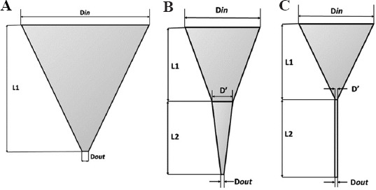
Diagram of selected nozzle geometry. (A) Tapered conical nozzle. (B) Conical nozzle. (C) Cylindrical nozzle.
Table 1.
Nozzle parameters for the three nozzle geometries
| Nozzles | Din(mm) | D’’ (mm) | Dout(mm) | L1 (mm) | L2 (mm) | a1 | a2 |
|---|---|---|---|---|---|---|---|
| Tapered conical | 10 | 0.1 | 10 | 26.84 | |||
| Tapered conical | 10 | 0.3 | 10 | 25.87 | |||
| Tapered conical | 10 | 0.5 | 10 | 25.41 | |||
| Conical | 10 | 3 | 0.1 | 10 | 10 | 19.29 | 8.25 |
| Conical | 10 | 3 | 0.3 | 10 | 10 | 19.29 | 7.69 |
| Conical | 10 | 3 | 0.5 | 10 | 10 | 19.29 | 7.13 |
| Cylindrical | 10 | 0.1 | 0.1 | 10 | 10 | 26.34 | |
| Cylindrical | 10 | 0.3 | 0.3 | 10 | 10 | 25.87 | |
| Cylindrical | 10 | 0.5 | 0.5 | 10 | 10 | 25.41 |
2.2. Bioinks
Four different bioinks whose viscous behavior was described by the power-law viscosity model for non-Newtonian fluids (Equation 1) were chosen from existing literature, and the power-law parameters along with the density are tabulated in Table 2.
Table 2.
Power law parameters and density of bioinks
| Bioink | K (Pa.s) | n | Density (kg/m3) | Reference |
|---|---|---|---|---|
| Ink 6040 (NFC/alginate) | 109.73 | 0.154 | 998.2 | Dharmadasa[16] |
| CELLINK Bioink | 102.53 | 0.170 | 1000 | Gómez-Blanco, Mancha-Sánchez, Marcos[8] |
| Alginate-Sulfate Nanocellulose | 56.503 | 0.0863 | ~1000 | Müller, Öztürk, Arlov[17] |
| CM-cellulose + Alginate + k-carrageenan + Gelatin | 24.943 | 0.505 | 1039.8 | Pössl[20] |

Where, η is the viscosity (Pa s), n is the power-law constant (unitless), γ is the shear strain rate (s−1), and K is the flow consistency index (Pa s). The initial viscosity of the bioink is given by K and is related to the extrudability of bioinks, with lower values indicating higher extrudability[13]. Based on the flow behavior index, n: if 0 < n <1, then, the fluid shows pseudo-plastic or shear-thinning behavior, with a smaller value of n meaning a greater degree of shear-thinning. If n = 1, the fluid shows Newtonian behavior, and if n > 1, the fluid shows dilatant or shear-thickening behavior with a higher value of n resulting in greater thickening[14].
Several studies have previously used the shear-dependent power-law to simulate the flow of non-Newtonian bioinks in different nozzle geometries using empirically obtained K and n values from curve approximation[2,8,15-17]. In addition, Markstedt et al.[18] used a linear PTT model in IPS IBOFlow, whereas Emmermacher et al.[9] used a model based on Herschel-Bulkley law to simulate the fluid flow inside the nozzle. The Herschel-Bulkley and Carreau-Yasuda model were considered but the value for required parameters was not readily available for chosen bioink, whereas n and K values were more readily available in the literature. All the chosen bioinks exhibit shear thinning, that is, viscosity decreases when shear rate increases. Shear-thinning is a desirable property in bioinks as it is crucial in determining printability by preventing clogging of nozzle and reducing shear stress, leading to greater cell survivability[19]. The bioinks were added into ANSYS Fluent® as user-defined materials with the density and power-law parameters enlisted in Table 2.
2.3. Simulations
Steady-state simulations were run in ANSYS Fluent® with each of the bioinks comprising the fluid domain. The boundary conditions were set to 0-gauge pressure at the outlet and six different values for inlet pressure were chosen: 0.025 MPa, 0.050 MPa, 0.10 MPa, 0.15 MPa, 0.20 MPa, and 0.25 MPa, similar to values found in the literature[20-22]. For the printing speed, multiphase volume of fluid transient simulations were run for 1000 timesteps with step size of 0.01 s, giving a flowtime of 10 s. The inlet condition was chosen as a constant mass flow rate of 0.0015 kgs−1 and ink6040 was used as the extruded bioink. The substrate was set as a moving wall condition with the desired translational speed (1 mms−1, 5 mms−1, and 10 mms−1) corresponding to the printing speed, whereas the nozzle position was stationary. As described by Talluri[23], the movement of the nozzle is proportional to the movement of the substrate (bottom wall), and acceleration is approximately 0. This means that the simulation with moving substrate is equivalent to the simulation with moving nozzle. The pressure-implicit with splitting of operators (PISO) method was used as pressure-velocity coupling, and either the first- or second-order upwind was used to discretize momentum. PISO was chosen because solution convergence was obtained within acceptable computational time without having to use even smaller timestep and lower iteration per timestep.
There are some inherent assumptions made while using computational simulations to reduce the complexity of the simulations. It was assumed that (a) there was no slip between the bioink and the wall of the nozzle boundary condition of the nozzle wall; (b) the flow of bioink is incompressible, meaning its density is constant; and (c) the flow of the fluid is laminar.
3. Results and discussion
3.1. Nozzle geometry
In general, as shown in Figure 2, the tapered conical nozzle has a lower value for maximum wall shear stress (MWSS) than the conical nozzle, except for a dispensing pressure equal to 0.025 MPa for a given outlet diameter. The cylindrical nozzle with an outlet diameter of 0.5 mm has greater MWSS than the corresponding conical and tapered conical nozzle for inlet pressure >0.15 MPa. Besides this, the MWSS is lower in the cylindrical than the tapered conical and conical nozzles for all other combinations. This indicates that the cells would have higher survivability in the cylindrical nozzle. However, on examining the contours of MWSS for the three nozzles of outlet diameter 0.30 mm at 0.2 MPa presented in Figure 3, the region where the most wall shear stress is experienced by the cell is confined closer to just the outlet region of the tapered conical (Figure 3A) and conical nozzle (Figure 3B), which agrees with the findings of Liu et al.[24] and Gómez-Blanco et al.[8]. In contrast, for the cylindrical nozzle, the entirety of the cylindrical portion of the nozzle experiences a greater wall shear stress (Figure 3C). While this particular combination was chosen as a representative condition to demonstrate where the region of MWSS occurred across the three nozzles, similar characteristic contours were attained for other combination of outlet diameter and pressure. The region of maximum shear stress is longer in cylindrical nozzle because it has a uniform radius and requires a constant pressure throughout for extrusion in contrast to conical needles where high pressure is only needed at the tip of the nozzle[25]. Billiet et al.[15] also compared conical and cylindrical nozzle of internal diameter 200 mm at 1 bar inlet pressure and noted that the conical nozzle experienced greater shear stress for approximately 1 mm near the outlet, but the cylindrical nozzle experienced lower shear stress for >16 mm from the nozzle. This meant that cell death was higher in the cylindrical nozzle due to the higher passage time in the high shear stress region. This observation is indicative of the reduced cell viability in tubular (cylindrical) nozzles compared to conical nozzles, as shown by experimental observations[26,27].
Figure 2.
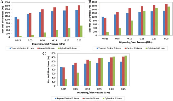
Variation of maximum wall shear stress with respect to different nozzle geometry at constant pressures. (A) 0.1 mm. (B) 0.3 mm. (C) 0.5 mm.
Figure 3.
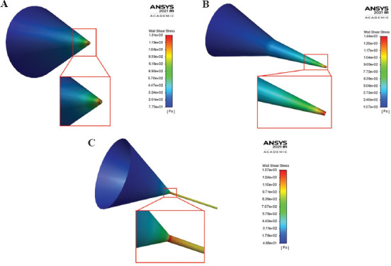
Contour of wall shear stress for (A) tapered conical, (B) conical, and (C) cylindrical nozzle with outlet diameter 0.3 mm at inlet pressure 0.20 MPa with regions of MWSS emphasized.
The cylindrical nozzles that have a smaller volumetric footprint compared to the conical nozzle are ideal for printing in confined spaces and can reduce wastage of bioink, which is an added benefit while using expensive biomaterials or cells[7]. Although the MWSS in the cylindrical nozzle is much lower, the mass flow rate is comparatively lower than the tapered conical and conical nozzle for the same nozzle diameter and pressure, as shown in Figure 4. Since the flow rate is proportional to the applied pressure, increased pressure translates to an increased flow rate[28]. This means that to achieve the same flow rate in the cylindrical nozzle as in the conical and tapered conical nozzle, a greater pressure would be required, which consequently increases shear stress[17]. In our simulations, an inlet mass flow rate >0.003 kg/s was obtained in a cylindrical nozzle with an outlet diameter of 0.50 mm only at 0.25 MPa inlet pressure with a corresponding MWSS of 1490 Pa. In contrast, an inlet mass flow rate >0.003 kg/s was obtained in a tapered conical and conical nozzle with outlet diameter 0.50 mm at 0.15 MPa inlet pressure with a corresponding MWSS of 1142 Pa and 1360 Pa, respectively. The difference in mass flow rate was more drastic at lower inlet pressure values; for instance, the mass flow rates were 0.0017 kg/s and 0.0015 kg/s for tapered conical and conical nozzles, respectively, but the mass flow rate for the cylindrical nozzle was 0.00014 kg/s at an inlet pressure of 0.05 MPa. Consequently, at equivalent flow rates, cell damage was lower in a tapered needle compared to a cylindrical one[27].
Figure 4.
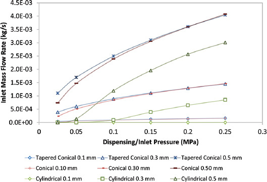
Graph of inlet mass flow rate with respect to pressure for different nozzles.
3.2. Nozzle diameter
As shown in Figure 5, for both tapered conical and conical nozzles, our findings agree that as the nozzle diameter increases from 0.1 mm to 0.5 mm, the MWSS decreases under constant pressure, possibly leading to greater cell viability. As shown in Table 3, the decrease of the diameter from 0.5 mm to 0.1 mm increases the MWSS by approximately 30% for the tapered conical nozzle and by 25% for the conical nozzle at a given pressure. However, for the cylindrical nozzle, the MWSS is the lowest for nozzle diameter 0.1 mm, and the maximum shear stress increases as outlet nozzle diameter increases. In addition, while the cylindrical nozzle with a diameter of 0.3 mm has a lower shear stress than the cylindrical nozzle with a diameter of 0.5 mm, for pressures higher than 0.2 MPa, the wall shear stress is greater in the cylindrical nozzle with outlet diameter 0.3 mm. One explanation for these deviations from the expected result for the cylindrical nozzles can be accounted to the choice of inlet condition as constant pressure. There is a significant increase in the flow rate, as evident in Figure 6, to maintain a constant pressure difference, which leads to the increased MWSS in the nozzle with the largest outlet diameter[12].
Figure 5.
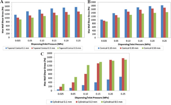
Variation of maximum wall shear stress with respect to different nozzle diameters at constant pressures for (A) tapered conical, (B) conical, and (C) cylindrical nozzles.
Table 3.
Percentage increase in maximum wall shear stress (Pa) on decreasing diameter of nozzle outlet from 0.5 mm to 0.1 mm
| Pressure (MPa) | Tapered conical | Conical | Cylindrical |
|---|---|---|---|
| 0.025 | 26.1 | 11.9 | −79.4 |
| 0.050 | 31.7 | 21.1 | −79.6 |
| 0.100 | 30.1 | 24.0 | −78.2 |
| 0.150 | 30.5 | 25.7 | −70.9 |
| 0.200 | 30.9 | 27.1 | −62.8 |
| 0.250 | 30.9 | 27.1 | −55.0 |
Figure 6.
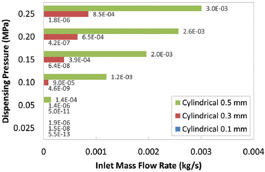
Inlet mass flow rate at specified pressures for cylindrical nozzles.
Cell survivability is crucial in the bioprinting process. As such, several studies have indicated the adverse effect on cell survivability with the decrease in nozzle diameter due to the increased shear forces experienced by the cells[29-31]. Conversely, an increase in nozzle diameter reduces the velocity gradient and thus reduces shear stress, in turn, increasing the cell survivability[22]. Although a larger outlet diameter increases flow rate and reduces shear stress, it also results in lower resolution; a smaller outlet diameter with higher inlet pressure gives higher resolution[2]. It is crucial to balance both cell survivability and printing resolution to obtain an optimum result.
3.3. Dispensing pressure
Cells are exposed to various mechanical forces while moving through the nozzles; this generates internal pressures that can damage the cells[7]. These forces are directly proportional to the dispensing pressure as it determines the force with which the extruded material is being pushed. Increasing the dispensing pressure also increases the MWSS, much like decreasing the nozzle diameter. Nair et al.[31] suggested that the effect of increasing the inlet pressure has a more prominent negative effect on cell viability than nozzle diameter. However, taking into consideration, the maximum percentage increase in wall shear stress on increasing the pressure by 5 times (Table 4) and decreasing the outlet diameter by a factor of 5 at constant pressure (Table 3), our results do not conclusively show the more pronounced effect of inlet pressure. At a given outlet diameter, our findings suggest that on increasing the pressure from 0.05 MPa to 0.25 MPa, the increase in MWSS is highest in the cylindrical nozzle followed by the conical and finally tapered conical nozzle. Furthermore, the variation of the overall percentage increase in MWSS is lower for tapered conical and conical nozzles as compared to the cylindrical nozzle of different outlet diameter, as shown in Table 4.
Table 4.
Percentage increase in maximum wall shear stress (Pa) on increasing pressure from 0.05 MPa to 0.25 MPa for different outlet nozzle diameter
| Diameter (mm) | Tapered conical | Conical | Cylindrical |
|---|---|---|---|
| 0.1 | 16.5 | 32.6 | 401.9 |
| 0.3 | 17.9 | 33.1 | 290.3 |
| 0.5 | 17.2 | 26.3 | 127.5 |
In addition, a very low inlet pressure will result in no or little bioink being deposited, whereas a very high pressure will result in excess bioink being deposited[7]. It is very important to obtain a higher volumetric flow because it leads to a faster dispensing speed so as to shorten the time for the cells under pressure. However, the overall volumetric flow cannot be fully controlled by the dispensing pressure alone as it depends on the fluid viscosity and the inner geometry where the fluid flows[8]. Thus, the optimum dispensing pressure varies for different nozzles.
From Figure 7, the best pressure ranges are in the regions where there is a linear relationship between the pressure and the shear stress with a gentle slope. In these regions, it is easier to control the cell viability and volumetric flow. As we can see, these regions are different for all the nozzles. When determining the optimum working pressure, it is recommended to choose the lower pressures from the pressure ranges to reduce the risk of cell damage, but one must also consider the flow rate and choose the best compromise.
Figure 7.
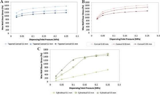
Variation of maximum wall shear stress of different nozzle diameters at different pressures. (A) Tapered conical. (B) Conical. (C) Cylindrical.
3.4. Bioink rheology
During extrusion bioprinting, bioinks go from a resting state to a high shear stress condition in the nozzle and then go back to a resting state. The decrease in the viscosity caused by the shear-thinning property of the bioink facilitates the deposition of the bioink and leads to high printing fidelity as shear stress is drastically reduced as the ink exits the nozzle[32]. The power-law constant (n) is representative of the bioink’s shear thinning behavior. Bioinks with lower value of n exhibit a more shear thinning behavior, that is, an increase in shear rate causes a greater decrease in the viscosity of the bioink. Figure 8 shows the results of the MWSS obtained for each of the nozzles with an outlet diameter of 0.3 mm using the four different bioinks at varying inlet pressure. Alginate-sulfate nanocellulose bioink with the lowest power-law constant value (n = 0.0863), that is, the highest shear thinning behavior experiences the lowest maximum shear stress. Ink6040 (n = 0.154) and CELLINK bioink (n = 0.170), both of which have similar n-value, show the same trend in MWSS with similar values. This is further supported by the fact that the viscosity is determined by the polymer concentration and molecular weight and both ink6040 and CELLINK bioink are made up of similar concentrations of nano-fibrillated cellulose and alginate, in the ratios of 60:40 and 80:20, respectively. In general, the results follow the expected trend, except for the inlet pressure value of 0.05–0.15 MPa in the cylindrical nozzle where the bioink with the highest n-value (0.5050) has a lower MWSS than the ink6040 and CELLINK bioink. When we look at the outlet mass flow rate for the four bioinks in the cylindrical nozzle, as shown in Figure 9, the flow rate of the CM-cellulose + Alginate + k-carrageenan + Gelatin bioink (n = 0.5050) has an almost negligible mass flow rate, indicating that the bioink is not extrudable at the lower values of dispensing pressure due to its weaker shear-thinning properties. The trend in the values of MWSS is similar for all the four bioinks in the tapered conical and conical nozzles, suggesting that the aforementioned observations and inferences for ink6040 with respect to dispensing pressure, nozzle geometry, and outlet diameter would hold for the three other bioinks. With that said, the effect of the power-law constant is confounded by the difference in the consistency index value (K) in the power-law equation.
Figure 8.
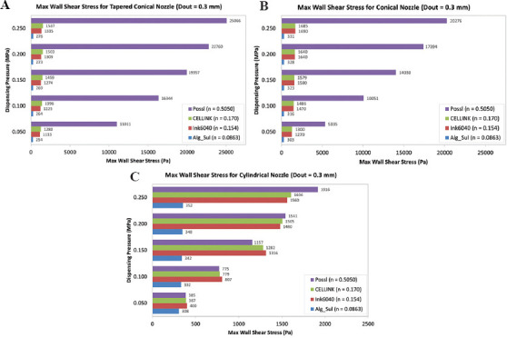
Graph of maximum wall shear stress at varying inlet pressure for bioinks with different power-law constant using (A) tapered conical nozzle (Dout = 0.3 mm), (B) conical nozzle (Dout = 0.3 mm), and (C) cylindrical nozzle (Dout = 0.3 mm).
Figure 9.
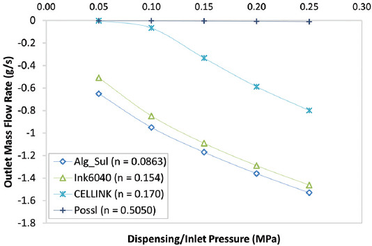
Line graph of outlet mass flow rate against inlet pressure for the four bioinks.
3.5. Printing speed
The 2D thread profiles for ink6040 in the conical nozzle with outlet diameter 0.3 mm obtained through transient simulations at printing speed 5 mms−1 for 10 s with an interval of 2 s are shown in Figure 10. The thread profiles for the other nozzles at varied printing speeds (1 mms−1, 5 mms−1, and 10 mms−1) at the same time intervals are shown in the Appendix Figures 1-9. Quantitative assessment of the thread profile using volume fraction of the bioink across all three nozzles shows that at lower printing speed, the strand of extruded bioink is continuous and uniform, but at higher printing speeds, the strand is discontinuous and smaller in width. Furthermore, the ideal printing speed seems to be the same regardless of the chosen nozzle geometry for a constant diameter at a constant inlet mass flow rate. A change in the strand width results in decreased accuracy of the printed strand at higher printing speed as observed experimentally[22]. As such, using CFD to simulate the effect of printing speed can assist in identifying the ideal printing speed for a given bioink in a particular system.
Figure 10.
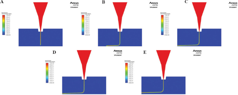
Contour of volume fraction for extruded bioink in conical nozzle with printing speed 5 mms−1 at (A) 2 s, (B) 4 s, (C) 6 s, (D) 8 s, and (E) 10 s.
As shown in Figure 11A, in general, the conical nozzle has the lowest outlet velocity, whereas the cylindrical nozzle has the highest outlet velocity. This result is contrary to the result expected from the steady-state simulations, but it can be explained by the choice of constant inlet mass flow rate used for the transient simulations contrary to the constant inlet pressure for the steady simulations. For the lower printing speed (1 mms−1 and 5 mms−1), the outlet velocity plateaued at a constant velocity throughout the simulation across all three nozzles. However, the variation in velocity was greater for the higher printing speed especially in the latter half of the simulations. A similar trend was observed in the case of the outlet pressure across the three nozzles, as shown in Figure 11B. These variations can be explained by looking at the strand profile for the individual simulations. Due to the higher translational velocity of the bottom wall, the strands moved further away from the nozzle, causing the thread profile to move upwards. For instance, in the case of the conical nozzle at 10 mms−1 (Appendix, Figure 3E), the strand was broken and caused coagulation at the outlet, which caused the fluctuation. In practical applications, the variations in the velocities are in terms of a fraction of millimeters, so it is unlikely that it would make a significant difference.
Figure 11.

Variation of (A) outlet velocity (m/s) and (B) outlet pressure (Pa) in the nozzle against time (s) for different printing speeds through transient simulation.
3.6. Empirical relationship
As cell viability and survivability are closely related to the shear stress experienced by the cell in the nozzle, predicting the amount of shear stress experienced by the cell can serve to increase cell viability. Nair et al.[31] developed an empirical model from experimental data to predict the degree of survivability of cells as a function of inlet pressure and outlet diameter. Since the dispensing pressure and diameters are independent variables, a complete second-order model with two independent variables can be expressed as shown in Equation 2[31].

Based on this, we fitted a second-degree curve to the results of our computational simulations to get an empirical relationship for ink6040 and estimate the MWSS (z) experienced in the nozzle as a function of the inlet pressure (x) used for extrusion and the outlet diameter of the nozzle (y). Empirical equations can be calculated similarly for other bioinks and could be used to compare the MWSS and, in turn, survivability of cells in different bioinks.
The surface plot for the observed relationship is shown in Figure 12 and the empirical relation is given by Equations 3, 4, and 5 for the tapered conical, conical, and cylindrical nozzles, respectively. For the cylindrical nozzle, the computational relationship suffers due to the wide variations in the MWSS (abbreviated as MWSS in the following equations) due to the effect of a drastic increase in flow rate to maintain the constant inlet pressure condition. As such, at low values of pressure and diameter, the model predicts a negative MWSS, as shown in Figure 12C.
Figure 12.
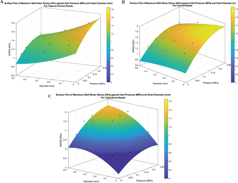
Surface plot for maximum wall shear stress (in kPa) for (A) tapered conical, (B) conical, and (C) cylindrical nozzles.


4. Conclusions
Our aim was to investigate the effect of crucial bioprinting parameters – nozzle geometry, nozzle diameter, inlet pressure, and bioink rheology, specifically, shear-thinning properties – on the MWSS and thus cell viability through computational simulation. In addition, we simulated the effect of printing speed on the thread profile along with outlet velocity and pressure. The main conclusions of our study can be summarized as follows:
In general, the MWSS for the tapered conical nozzle is lower than the conical nozzle, and the cylindrical nozzle has the lowest MWSS. However, the cells experience higher shear stress for a greater portion of the nozzle length in the cylindrical nozzle.
The flow rate of bioink is crucial in the investigation of shear stress. Higher pressure needs to be applied in the cylindrical nozzle to attain the same flow rate as the other two nozzles, resulting in higher shear stress. Increasing the pressure is a possible confounding factor because it increases mass flow rate which decreases the time spent by the cell under high shear stress.
Increasing the nozzle diameter increases mass flow rate and decreases the wall shear stress, but it may negatively affect the printing resolution.
Our findings do not suggest that increasing the inlet pressure has a more prominent negative effect than decreasing the outlet diameter.
We demonstrated that computational simulations can be used to generate a thread profile of printed strand and our simulations suggest that the ideal printing speed is independent of nozzle geometry for a constant nozzle diameter at a constant inlet mass flow rate.
We presented empirical relationships based on our simulations, which would facilitate comparisons amongst different bioinks and experimental setups.
Most importantly, the effects of these bioprinting parameters are in constant interplay with each other and they need to be considered as a whole to fully understand their effect in the bioprinting process. With CFD simulations, we could even observe the effect of these bioprinting parameters, which would not be possible in an experimental setup. It provides insights that may assist in optimizing the bioprinting parameters, developing and comparing different bioinks and experimental setups, and reducing the number of trial iterations required while bioprinting. As such, the efficiency of bioprinting processes can be increased and the development of novel approaches can be furthered.
The results for the cylindrical nozzle were confounded due to the drastic changes in mass flow rate, and hence, further simulations with a constant mass flow rate are needed. Three-dimensional simulations of the bioink thread profile under experimental conditions, simulations involving cells, and experimental verification of the results to validate the usefulness of the computational simulation are proposed as future work.
Acknowledgments
Beni Shimwa Muhire acknowledges NYU Abu Dhabi’s Virtual Summer 2021 Visiting Undergraduate Research Program for the opportunity to work on this project.
Funding
This research received no specific grant from any funding agency in the public, commercial, or not-for-profit sectors.
Conflicts of interest
The authors declare no conflicts of interest.
Authors’ contributions
R.C. carried out design of experiment, ran steady and transient simulation, and drafted and revised the manuscript. B.M. ran steady simulation and cowrote the manuscript. S.V. was responsible for ideation, manuscript review and editing, as well as overall supervision. Figure 12. Surface plot for maximum wall shear stress (in kPa) for (A) tapered conical, (B) conical, and (C) cylindrical nozzles.
References
- 1.Vijayavenkataraman S, Yan WC, Lu WF, et al. 3D Bioprinting of Tissues and Organs for Regenerative Medicine. Adv Drug Deliv Rev. 2018;132:296–332. doi: 10.1016/j.addr.2018.07.004. https://doi.org/10.1016/j.addr.2018.07.004. [DOI] [PubMed] [Google Scholar]
- 2.Magalhães IP, Oliveira PM, Dernowsek J, et al. Investigation of the Effect of Nozzle Design on Rheological Bioprinting Properties Using Computational Fluid Dynamics. Matéria (Rio de Janeiro) 2019;24:714. https://doi.org/10.1590/s1517-707620190003.0714. [Google Scholar]
- 3.Wang Z, Abdulla R, Parker B, et al. A Simple and High-resolution Stereolithography-based 3D Bioprinting System Using Visible Light Crosslinkable Bioinks. Biofabrication. 2015;7:045009. doi: 10.1088/1758-5090/7/4/045009. https://doi.org/10.1088/1758-5090/7/4/045009. [DOI] [PubMed] [Google Scholar]
- 4.Zhang J, Wehrle E, Rubert M, et al. 3D Bioprinting of Human Tissues:Biofabrication, Bioinks, and Bioreactors. Int J Mol Sci. 2021;22:3971. doi: 10.3390/ijms22083971. https://doi.org/10.3390/ijms22083971. [DOI] [PMC free article] [PubMed] [Google Scholar]
- 5.Biazar E, Najafi SM, Heidari KS, et al. 3D Bio-printing Technology for Body Tissues and Organs Regeneration. J Med Eng Technol. 2018;42:187–202. doi: 10.1080/03091902.2018.1457094. https://doi.org/10.1080/03091902.2018.1457094. [DOI] [PubMed] [Google Scholar]
- 6.Boularaoui S, Al Hussein G, Khan KA, et al. An Overview of Extrusion-based Bioprinting with a Focus on Induced Shear Stress and its Effect on Cell Viability. Bioprinting. 2020;20:e00093. [Google Scholar]
- 7.Bahrd A. Computational Fluid Dynamics and Quantitative Cell Viability Measurements in Dispensing-Based Biofabrication. 2017:37. [Google Scholar]
- 8.Gómez-Blanco JC, Mancha-Sánchez E, Marcos AC, et al. Bioink Temperature Influence on Shear Stress, Pressure and Velocity Using Computational Simulation. Processes. 8:865. [Google Scholar]
- 9.Emmermacher J, Spura D, Cziommer J, et al. Engineering Considerations on Extrusion-based Bioprinting:Interactions of Material Behavior, Mechanical Forces and Cells in the Printing Needle. Biofabrication. 2020;12:025022. doi: 10.1088/1758-5090/ab7553. [DOI] [PubMed] [Google Scholar]
- 10.Göhl J, Markstedt K, Mark A, et al. Simulations of 3D Bioprinting:Predicting Bioprintability of Nanofibrillar Inks. Biofabrication. 2018;10:034105. doi: 10.1088/1758-5090/aac872. https://doi.org/10.1088/1758-5090/aac872. [DOI] [PubMed] [Google Scholar]
- 11.Gómez-Blanco JC, Mancha-Sánchez E, Ortega-Morán JF, et al. Computational Fluid Dynamics Study of Inlet Velocity on Extrusion-Based Bioprinting. in XV Mediterranean Conference on Medical and Biological Engineering and Computing MEDICON 2019. Cham: Springer International Publishing; 2020. [Google Scholar]
- 12.Reina-Romo E, Mandal S, Amorim P, et al. Towards the Experimentally-Informed In Silico Nozzle Design Optimization for Extrusion-Based Bioprinting of Shear-Thinning Hydrogels. Front Bioeng Biotechnol. 2021;9:701778. doi: 10.3389/fbioe.2021.701778. https://doi.org/10.3389/fbioe.2021.701778. [DOI] [PMC free article] [PubMed] [Google Scholar]
- 13.Gillispie G, Prim P, Copus J, et al. Assessment Methodologies for Extrusion-Based Bioink Printability. Biofabrication. 2020;12:022003. doi: 10.1088/1758-5090/ab6f0d. https://doi.org/10.1088/1758-5090/ab6f0d. [DOI] [PMC free article] [PubMed] [Google Scholar]
- 14.Rapp BE. Fluids, in Microfluidics:Modeling, Mechanics and Mathematics. Amsterdam, Netherlands: Elsevier; 2016. pp. 250–51. [Google Scholar]
- 15.Billiet T, Gevaert E, De Schryver R, et al. The 3D Printing of Gelatin Methacrylamide Cell-laden Tissue-engineered Constructs with High Cell Viability. Biomaterials. 2014;35:49–62. doi: 10.1016/j.biomaterials.2013.09.078. https://doi.org/10.1016/j.biomaterials.2013.09.078. [DOI] [PubMed] [Google Scholar]
- 16.Dharmadasa V. Department of Mechanics. Sweden: KTH Royal Institute of Technology; 2016. Investigation of Cell-viability in the Bioprinting Process; p. 54. [Google Scholar]
- 17.Müller M, Öztürk E, Arlov O, et al. Alginate Sulfate-Nanocellulose Bioinks for Cartilage Bioprinting Applications. Ann Biomed Eng. 2017;45:210–23. doi: 10.1007/s10439-016-1704-5. https://doi.org/10.1007/s10439-016-1704-5. [DOI] [PubMed] [Google Scholar]
- 18.Markstedt K, Mantas A, Tournier I, et al. 3D Bioprinting Human Chondrocytes with Nanocellulose-Alginate Bioink for Cartilage Tissue Engineering Applications. Biomacromolecules. 2015;16:1489–96. doi: 10.1021/acs.biomac.5b00188. [DOI] [PubMed] [Google Scholar]
- 19.Wu Y, Wenger A, Golzar H, et al. 3D Bioprinting of Bicellular Liver Lobule-mimetic Structures via Microextrusion of Cellulose Nanocrystal-incorporated Shear-thinning Bioink. Sci Rep. 2020;10:77146. doi: 10.1038/s41598-020-77146-3. https://doi.org/10.1038/s41598-020-77146-3. [DOI] [PMC free article] [PubMed] [Google Scholar]
- 20.Pössl A. A Targeted Rheological Bioink Development Guideline and its Systematic Correlation with Printing Behavior. Biofabrication. 2021;13:035021. doi: 10.1088/1758-5090/abde1e. [DOI] [PubMed] [Google Scholar]
- 21.Paxton N, Smolan W, Böck T, et al. Proposal to Assess Printability of Bioinks for Extrusion-based Bioprinting and Evaluation of Rheological Properties Governing Bioprintability. Biofabrication. 2017;9:044107. doi: 10.1088/1758-5090/aa8dd8. https://doi.org/10.1088/1758-5090/aa8dd8. [DOI] [PubMed] [Google Scholar]
- 22.Webb B, Doyle BJ. Parameter Optimization for 3D Bioprinting of Hydrogels. Bioprinting. 2017;8:8–12. [Google Scholar]
- 23.Talluri DJ. Numerical Modeling of the Fiber Deposition Flow in Extrusion-Based 3D Bioprinting. Rowan University; Ann Arbor: 2021. p. 103. [Google Scholar]
- 24.Liu W, Heinrich MA, Zhou Y, et al. Extrusion Bioprinting of Shear-Thinning Gelatin Methacryloyl Bioinks. Adv Healthc Mater. 2017;6:1601451. doi: 10.1002/adhm.201601451. https://doi.org/10.1002/adhm.201601451. [DOI] [PMC free article] [PubMed] [Google Scholar]
- 25.Kraynak J. Minimizing Cell Death During the Extrusion Bioprinting of Gelatin-Alginate Bioinks. Temple University, Libraries; 2021. [Google Scholar]
- 26.Anandan A, Courtial EJ, Lemarié L, et al. Rheology, Simulation and Data Analysis toward Bioprinting Cell Viability Awareness. Bioprinting. 2020;21:e00119. https://doi.org/10.1016/j.bprint.2020.e00119. [Google Scholar]
- 27.Li M, Tian X, Schreyer DJ, et al. Effect of Needle Geometry on Flow Rate and Cell Damage in the Dispensing-based Biofabrication Process. Biotechnol Prog. 2011;27:1777–84. doi: 10.1002/btpr.679. https://doi.org/10.1002/btpr.679. [DOI] [PubMed] [Google Scholar]
- 28.Udofia E, Zhou W. Solid Freeform Fabrication 2018:Proceedings of the 29th Annual International Solid Freeform Fabrication Symposium an Additive Manufacturing Conference. Austin, TX: 2018. Microextrusion Based 3D Printing a Review. [Google Scholar]
- 29.Blaeser A, Campos DF, Puster U, et al. Controlling Shear Stress in 3D Bioprinting is a Key Factor to Balance Printing Resolution and Stem Cell Integrity. Adv Healthc Mater. 2016;5:326–33. doi: 10.1002/adhm.201500677. https://doi.org/10.1002/adhm.201500677. [DOI] [PubMed] [Google Scholar]
- 30.Chang R, Sun W. Effects of Dispensing Pressure and Nozzle Diameter on Cell Survival from Solid Freeform Fabrication-based Direct Cell Writing. Tissue Eng Part A. 2008;14:41–48. doi: 10.1089/ten.a.2007.0004. https://doi.org/10.1089/ten.a.2007.0004. [DOI] [PubMed] [Google Scholar]
- 31.Nair K, Gandhi M, Khalil S, et al. Characterization of Cell Viability during Bioprinting Processes. Biotechnol J. 2009;4:1168–77. doi: 10.1002/biot.200900004. https://doi.org/10.1002/biot.200900004. [DOI] [PubMed] [Google Scholar]
- 32.Hölzl K, Lin S, Tytgat L, et al. Bioink Properties before, during and after 3D Bioprinting. Biofabrication. 2016;8:032002. doi: 10.1088/1758-5090/8/3/032002. https://doi.org/10.1088/1758-5090/8/3/032002. [DOI] [PubMed] [Google Scholar]


