Abstract
Hollow microneedle patches (HMNPs) have great promise for efficient and precise transdermal drug delivery in a painless manner. Currently, the clinical application of HMNPs is restricted by its complex manufacturing processes. Here, we use a new three-dimensional (3D) printing technology, static optical projection lithography (SOPL), for the fast fabrication of HMNPs. In this technology, a light beam is modulated into a customized pattern by a digital micromirror device (DMD) and projected to induce the spatial polymerization of monomer solutions which is controlled by the distribution of the light intensity in the monomer solutions. After an annulus picture is inputted into the DMD via the computer, the microneedles with hollow-cone structure can be precisely printed in seconds. By designing the printing pictures, the personalized HMNPs can be fast customized, which can afford the scale-up preparation of personalized HMNPs. Meanwhile, the obtained hollow microneedles (HMNs) have smooth surface without layer-by-layer structure in the commonly 3D-printed products. After being equipped with a micro-syringe, the HMNPs can efficiently deliver insulin into the skin by injection, resulting in effective control of the blood glucose level in diabetic mice. This work demonstrates a SOPL-based 3D printing technology for fast customization of HMNPs with promising medical applications.
Keywords: Microneedle, Three-dimensional printing, Hollow microneedle patches, Fabrication, Drug delivery
1. Introduction
Microneedles are micron-sized needles, capable of perforating stratum corneum painlessly and delivering drugs into the body. The primary superiority of microneedles is that they combine the potential delivery ability of a hypodermic needle with the user-friendly benefits of a percutaneous patch. Based on the application characteristics of microneedles, they can be divided into solid microneedles, coated microneedles, dissolving microneedles, porous microneedles, and hollow microneedles (HMNs). The pretreatment of skin with solid microneedles in advance promotes the permeation of transdermal preparations (e.g., ointments, gels, and emulsions). Solid microneedles can also be used to destroy the skin cell structures and induce the expression and deposition of elastin and collagen. Coated microneedles deliver the drugs coated on the surface of microneedles into the skin. Dissolving microneedles are made of dissolvable materials and release the drugs after microneedle dissolution. Porous microneedles release the drug into the skin through the pores of the needle body, such as swelling hydrogel-forming microneedle[1], and other porous microneedles[2-4]. HMNs can be regarded as scaled-down traditional hypodermic needles with a micron-level length and diameter. When connected to a syringe or device, they have the potential to replace syringe-based administration that usually causes fear in the user. Compared with the other four types of microneedles, HMNs have major advantages, such as rapid drug delivery directly into the body without a time-consuming slow penetration and release process, and a higher drug utilization rate. By combining with the minimally invasive, painless, and convenient delivery of microneedles, HMNs have been used for transdermal drug delivery of insulin[5,6], vaccine[7,8], lidocaine,[9] etc.
HMN patches (HMNPs) are commonly fabricated using microelectromechanical systems (MEMS) techniques, including photolithography[10,11], etching[12,13], laser direct writing,[14] etc. In these methods, a thin substrate film is firstly created by chemical, physical vapor deposition, or spin coating. Next, the two-dimensional master pattern of the required material is transferred from the original photomask to the photosensitive film on the substrate by photolithography technology. Finally, microneedles are made by wet or dry (plasma-based) etching[15]. However, MEMS techniques cannot achieve the high-precision manufacturing of HMNs with fine structures. In addition, MEMS techniques can hardly be used for customization and large-scale manufacturing because of the cumbersome, time-consuming, and costly manufacturing processes. Therefore, the translation of HMNPs to clinical applications is challenging and novel techniques for rapid fabrication of HMNPs are urgently needed.
Recently, three-dimensional (3D) printing technology has been used to flexibly customize with intricate structures, and the manufacturing period has been decreased to dozens of minutes[14,16-18]. For example, laser stereolithography (SLA) can be used to fabricate cone- and pyramid-shaped HMNs and basic syringe-shaped needle arrays (12.5 min are needed for the generation of each device)[17]. Liquid crystal display vat polymerization and digital light processing (DLP) have an improved molding speed when constructing HMNs[16,19]. These 3D printing technologies shorten the fabrication period and simplify the production processes of customized HMNs. However, layer-by-layer additive manufacturing always resulted in a layered structure, which affects the mechanical properties of the microneedle and potentially causes needle break and penetration failure during use. The layer-by-layer structure can be improved by high printing precision, such as high-precision two-photon polymerization (TPP). Moreover, TPP enables the fabrication of HMNs with various straightforward shapes and small openings[20] as well as in-plane and out-of-plane microneedles with different aspect ratios[18,21]. However, it requires a long period to prepare microneedle arrays (10 min per needle) by TPP[14], leaving considerable room for improvement in terms of fabrication speed. Together, it remains a challenge to rapidly fabricate high-quality HMNs. Nonetheless, our group developed a 3D printing technology, namely static optical projection lithography (SOPL), for rapid customizing high-quality solid microneedle arrays[22]. The obtained solid microneedles do not have the stair-like surface and layer-by-layer structure that are associated with the common 3D-printing technologies.
Herein, we innovatively use the SOPL technique for rapid customization of HMNPs within 5 s. In this technology, the digital light is modulated by a digital micromirror device (DMD) and projected to induce spatial polymerization controlled by the distribution of the light intensity in the monomer solutions. After an annulus picture is inputted into the DMD via the computer, the microneedles with hollow-cone structure can be precisely printed in seconds. By adjusting printing pictures, various structures of HMNs can be customized. The obtained HMNs have smooth surfaces and good mechanical properties. After being equipped with a micro-syringe, the HMNP enables the quantitative, minimally invasive, and pain-free insulin injection, which greatly reduces physical pain and mental anguish.
2. Materials and methods
2.1. Materials
Photosensitive resin was purchased from Ausbond (China). Cell-Counting Kit-8 was purchased from SUNBAO BIOTECH (China). Quick-drying adhesive was obtained from ergo (Switzerland). Agarose gel was purchased from Bioweste (Spain). Insulin injection was purchased from Jiangsu Wanbang Biochemical Medicine Co., Ltd (China). Streptozocin (STZ) was purchased from BioFroxx (Germany). All chemical reagents were of analytical grade. C57BL/6 mice were provided by Chengdu Dossy Experimental Animals Co., LTD. Animal studies were in compliance with the guidelines for the ethical use of animals and were conducted at State Key Laboratory of Biotherapy, Sichuan University, China.
2.2. HMNPs customized by SOPL
The main modules for SOPL equipment to prepare HMNPs are excitation light source, DMD chip, high magnification micromirror, and reservoir. Printing picture is one of the key points of this technology. The printing picture of a HMN, made of Adobe Photoshop CC 2019, consists of two non-concentric circles, which can be regarded as an annulus. Its small inner circle represents the unexposed area, while the large outer circle represents the exposed area. Large circle and small circle are overlaid to form an annular pattern of the exposure area. The size of the large white circle represents the bottom size of the HMN. The size of the small black circle and the relative position to the large circle represent the opening size and opening position of the HMN, respectively.
The preparation of the HMN was as follows: First, the printing picture of the HMN was inputted into a DLP LightCrafter 4500 Control Software. Second, a light beam (405 nm) was modulated into the customized pattern of the HMN by DMD on the basis of the aforementioned printing picture. Thirdly, digital light projected from DMD was adjusted by a high magnification microlens to improve the printing resolution. Finally, the resin in the reservoir was solidified according to the special spatial distribution of digital light in the monomer solutions and a 3D structure was formed. In addition, various structures of HMNs were prepared by adjusting printing pictures.
HMNPs were fabricated to prepare HMN syringes. The printing picture of the HMN array and substrate were drawn respectively. Multiple annular pictures were arranged to form a printing picture of the HMN array. The printing picture of the substrate was set as a rectangular picture with large white circles of HMNs turned to nonexposed area. The glass slide was placed on a photosensitive resin bath before printing. The HMNP was printed consecutively in two steps. First, the photosensitive resin underwent polymerization under the first projected light pattern originating from the printing picture of HMN array and HMNs formed. Then, the second projected light pattern from the printing picture of the substrate was exposed in turn, and the substrate of the HMNP was printed and the HMMP was obtained.
The morphology of 3D-printed HMNs and HMNPs were observed by the camera and scanning electron microscope (SEM) (JSM-7500F) at 15 kV.
2.3. Simulation of the HMN formation process
To visualize the diffractive lithography by microlens effect and the complicated diffracted intensity distribution within the photosensitive resin in our fabrication, numerical simulation was implemented using an electromagnetic wave beam envelope module in COMSOL Multiphysics software. The ultraviolet (UV) light electric field when z = 0 (the surface of liquid resin), namely, E (r’, 0) was introduced as uniform distribution propagating along the positive z-direction. The original intensity at z =0 was set as I0 = 30 mW.cm–2, according to the UV power measurement and the attenuation coefficients along needle growing direction were set as C0=0.9627, C1=0, and C2=0.002878, respectively[23,24].
2.4. Post-treatment of HMNPs
The printed HMNPs were separated from the glass slide with a sharp blade. Since there were residual uncured materials on the printed products, HMNPs were soaked in anhydrous ethanol 3 times (each with 2 min) to completely remove the residual resin on the surface and in the cavity of microneedles. HMNPs were then dried. To enhance the mechanical properties of printed objects, HMNPs were exposed to UV-visible radiation at 450 nm under a light-emitting diode, LED lamp for 3 min to polymerize remaining uncured resin. They were successively soaked in 75% ethanol for 24 h and ×1 phosphate-buffered saline (PBS) for 24 h to improve the biocompatibility of HMNPs. The resultant HMNPs were dried at room temperature before used.
2.5. In vitro biocompatibility of HMNPs
In accordance with EN ISO 10993-12:2012 guidelines, the in vitro biocompatibility of HMNPs was conducted using six 1 cm3 cubes with the same printing materials and post-processing as HMNPs. The cubes were soaked in 6 ml of PBS for 24 h to obtain the extract of printing materials[25’26]. Skin cells of human adult low calcium high temperature (HaCaT, human-immortalized keratinocytes) and human dermal fibroblast (HDF) were used to assess the toxicity of the printed HMNPs. Cells were cultured in each well of 96-well microtiter plates, treated with 180 ml of fresh culture medium plus 20 ml of the extract for each well. The negative control was incubated with 180 ml of fresh culture medium and 20 ml of sterile PBS. After incubated for 24 h (day 1) and 72 h (day 3), CCK-8 assay was used to analyze cell viability with an absorbance wavelength of 450 nm.
2.6. Mechanical strength testing of HMNs
Compression test of a single HMN was performed to investigate the mechanical property of HMNs by a dynamic mechanical analysis (DMA) (Q800 TA Instruments). In brief, a single HMN was placed on the test stage positioned vertically and a metal probe was moved to the point where it touched the tip of HMN. The metal probe was then moved vertically downward at a compressive force of 2.5 N/min. The deformation process of the HMN during compression tests was captured by a camera. The relationship between compression displacement and static force was recorded by TA Instruments Universal Analysis 2000 (software of DMA). The fracture (failure) force was the turning point of static force on the curve.
2.7. Puncture experiment and skin healing experiment
Puncture experiment was applied on the skin of mice to evaluate the skin insertion ability of HMNPs. The hair on the back of mouse was shaved and depilated immediately after death by over anesthesia of the mouse and then wiped clean with saline. HMNPs were inserted into the dorsal skin of mice for 3 min to check their puncture ability. Then, the treated skin was fixed with formalin for 48 h and rinsed with running water for 2 h. Samples were then dehydrated before they were embedded in paraffin. Five-micrometer-thick cross-sections were cut from the samples followed by hematoxylin-eosin (H&E) staining. In addition, we applied HMNPs to the mouse skin for 3 min, and then removed them to verify whether the skin would quickly heal after microneedle treatment. The skin of mice was observed with the naked eye at 0, 10, 20, 30, 60, and 120 min after the HMNP application. Pictures were taken with a camera for recording them.
2.8. Preparation of HMN syringe
A 3D-printed HMNP was pasted after post-treatment on the punched steel plate with quick-drying adhesive. The punched steel plate had the same size as HMNP, and the holes in the plate correspond to the cavities of microneedles. The HMN syringe was then formed by connecting HMNP at one end of the converter and a micro-syringe at the other end. The converter was customized by 3D printing technology of SLA to match HMNPs and micro-syringes.
2.9. Delivery ability of HMN syringe in vitro
The agarose gel was used as an in vitro skin model and rhodamine as the model drug to assess the in vitro drug delivery ability of the HMN syringe. According to the literature[27], agarose powder was added with distilled water (0.0265 g/mL), heated to 100°C until completely dissolved, and then poured into the mold for cooling and molding for later use. Rhodamine was slowly injected into the above skin model using the HMN syringe, and the delivery process was photographed under an optical microscope.
2.10. Mouse models of diabetes
C57BL/6 mice were placed in a pathogen-free room with a 12 h light-dark cycle. The diabetic mouse was induced by STZ. Generally, male C57BL/6 mice (6 – 8 weeks old) were intraperitoneally injected with 2% STZ (150 mg/kg) after overnight fasting. Mice were then fed with a normal diet. One week later, the experiment was carried out in the morning where diabetic mice had fasted for 12 h. The blood was collected from tail clipping, and blood glucose levels were monitored with a glucometer of Yuwell. Fasting blood glucose higher than 16.7 mmol/L (or 300 mg/dl) were confirmed as type 1 diabetic mice and were used for further experiment[28].
2.11. Blood glucose control study in type 1 diabetic mice
The experiment began in the morning with diabetic mice fasted for 12 h. The hair of mice was partially shaved the day before the experiment to facilitate the injection. The initial blood glucose levels of the diabetic mice were measured at first. Diabetic mice with similar blood glucose were randomly divided into three groups (n = 5 for each group) with untreated diabetic mice as the negative control group, commercial insulin syringe as the positive control group, and HMN syringe group. The insulin injection dose of two IU/kg was selected for the positive control group and experimental group to avoid hypoglycemia. The blood glucose levels were then monitored at 0, 0.5, 1, 2, and 4 h after insulin injection. In the negative control group, mice received no other treatment except that blood was collected at the same time to monitor blood glucose levels.
2.12. Ethics statement
The experimental procedures were approved by the Institutional Animal Care and Use Committee of West China Hospital of Sichuan University (20211424A) and were performed in accordance with the guidelines and regulations of the Sichuan University Committee on Animal Research and Ethics.
2.13. Statistical/data analysis
All data were analyzed and arranged using GraphPad Prism 8 (GraphPad Software Inc., CA, USA). The significance of the data was calculated using Student’s t-test or one-way ANOVA methods. Results were presented as means with standard error of the mean and a P < 0.05 was considered statistically significant.
3. Results
3.1. HMNPs customized by SOPL
Schematic diagram for fabricating HMNPs via SOPL is depicted in Figure 1. During the printing process, according to the printing picture, a light beam was modulated into a customized pattern by a DMD and then passed through a high magnification microlens, which significantly improved the printing resolution to 5 μm. An annulus consisting of two non-concentric circles, namely a large white circle and a small black circle was designed in the printing picture to customize the HMN. The white circle represented the area exposed by the digital light, and the black circle was the unexposed area. The formation principle of HMNs was based on the spatial intensity distribution of projected annulus light. On the one hand, the light intensity distribution of circle light gradually weakened from the center of the focal plane to the outside and resembled an inverted cone. The small black circle represented nonexposed area, thus forming a hollow-cone structure. On the other side, the light intensity was greatly reduced after being absorbed by photosensitive resin according to the Beer-Lambert Law. The unique distribution of light intensity enabled the formation of HMNs accordingly. In addition, we simulated the light propagation and light intensity distribution during printing (see video in Supplementary File) to visualize the formation process of the HMN. It can be observed that the hollow-cone light intensity distribution was adjusted with the curing of the monomer solution, and finally, the HMN was formed.
Figure 1.
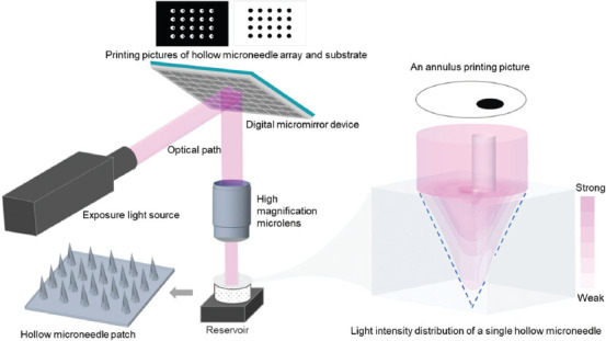
Schematic diagram of fabrication principle of hollow microneedle patches (HMNPs) via static optical projection lithography.
HMNs with three different opening sizes were obtained (Figure 2B and C) by adjusting the size of small black circles in printing pictures (Figure 2A). The opening sizes of HMNs enlarged with the increase of small black circles in size, and the bottom of HMNs remained unchanged when keeping large white circles unchanged. HMNs with five different opening positions are formed by adjusting the relative position of small black circles (Figure 3). The HMNs in Figure 3A-C had holes at the bottom; while HMNs in Figure 3D and E had no holes at the bottom. This is mainly due to the different intensity distribution of digital light in photosensitive resin. When the small black circle is too close to the edge of the large white circle, the exposure area at the edge is small and the light intensity is not enough to support the closed loop at the bottom of the HMN. When the small black circle is too close to the center of the large white circle, the stronger annular light will be scattered in the solution, thus blocking the cavity of the microneedle. All the HMNs can be fabricated by a single exposure within 5 s. These results indicate that SOPL technology can flexibly and rapidly customize HMNs with various structures, which may have broader applications. For instance, HMNs with large openings can be made into coated HMNs, which would increase drug loading efficiency[29].
Figure 2.
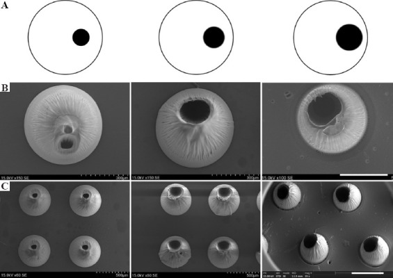
The morphologies of hollow microneedles (HMNs) observed by scanning electron microscope (SEM). As the size of small black circles in printing pictures increased, the opening sizes of HMNs were enlarged. (A) Printing pictures. (B) HMNs with different opening sizes (Scale bar: 300 μm). (C) HMN arrays with different opening sizes (Scale bar: 500 μm).
Figure 3.
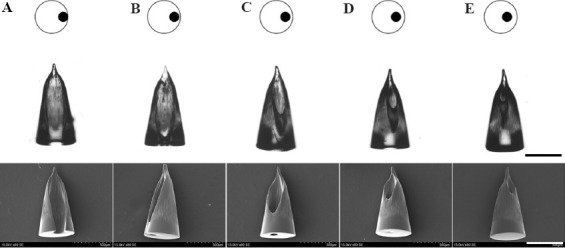
The morphologies of HMNs with different opening positions observed by SEM (Scale bars: 500 μm). (A-C) HMNs had holes at the bottom. (D-E) HMNs had no holes at the bottom.
HMNPs can be fabricated by sequentially exposing printing pictures of HMN arrays and substrates. SOPL technique can customize HMN arrays with various alignments by designing printing pictures. For example, HMNPs with the aligned arrangement and dislocated arrangement were portrayed in Figure 4A and B, respectively. As shown in Figure 4A, a 5 × 8 aligned HMNP could be obtained by exposing the specific printing pictures of the HMN array and the substrate in sequence. The dislocation-arranged HMNP could be prepared by changing the arrangement of the printing pictures (Figure 4B). It was worth noting that the printing picture of the substrate should be consistent with the arrangement of the large white circles. A 10 × 6 mm HMNP could be formed within 5 s via rapid photopolymerization. SEM showed that the height of each HMN was about 1000 mm. HMNs had distinct opening and sharp tip without the layered structure commonly associated with other 3D printing methods (Figure 4B).
Figure 4.
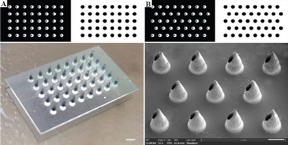
The printing pictures and morphologies of HMNPs. (A) A HMNP with aligned arrangement observed by camera (Scale bar: 1 mm). (B) A HMNP with dislocated arrangement observed by SEM (Scale bar: 500 μm).
In short, to fabricate the ideal HMNPs, the first step is to design printing pictures. For example, the sizes of the large white circle and the small black circle, which are related to the sizes of the bottom and opening of the HMNs. The relative position of the small black circle and the white circle is designed to prepare the suitable structure of HMN. The arrangement between the large white circles and the shape of the substrate determines the distribution of the microneedle array and the structure of the patch respectively. Then, according to the designed printing pictures, digital light allows the photosensitive materials to rapidly polymerize to form the HMNP without layer-by-layer structure. As a result, SOPL technology enables rapid customization of high-quality HMNPs.
3.2. In vitro biocompatibility of HMNPs
The safety issue of materials used in 3D printing was controversial[30] and the biocompatibility of the printing ink should be evaluated. In this study, the cytotoxicity of the extract of printing material was used to assess the in vitro biocompatibility of HMNP. The printed 1 cm3 cubes were processed according to section 2.4. Post-treatment of HMNPs for the extract, and then co-incubated with HaCaT and HDF cells. The relative cell viability of cells incubated with the extract of 3D printing material had no significant difference at 24 h (1 day) and 72 h (3 days) when compared with the cells incubated with PBS (Figure 5). This implies that 3D-printed HMNPs have no cytotoxicity to skin cells after post-treatment.
Figure 5.
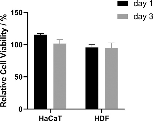
Relative cell viability of human adult low calcium high temperature (HaCaT) and human dermal fibroblast (HDF) cells as a percentage of their controls after 24 h and 72 h of incubation with 3D printed polymer extract. Data are mean ± standard error of the mean (n = 6).
3.3. Mechanical strength testing of HMNs
Microneedles must have enough mechanical strength to retain their intact shape when used for drug delivery. Therefore, it is necessary to test the mechanical strength of HMNs. The schematic diagram of mechanical test of a HMN is shown in Figure 6A. The HMN was placed on the test stage positioned vertically and a metal probe moved vertically downward at a compressive force of 2.5N/min. From the pictures of the compression process, the HMN initially remained intact, then gradually fractured (Figure 6B). Force-displacement curve showed the relationship between displacement and the force was almost linear at the outset. Thereafter, the HMN was broken, the curve shook suddenly, and the arrow in the figure indicated its turning point with the compression distance of about 250 mm and compression strength of about 4 N. It was reported that insertion forces of 0.1 – 3 N were sufficient to permit insertion by hand[31]. This reveals that the mechanical strength of HMNs is sufficient for skin puncture.
Figure 6.
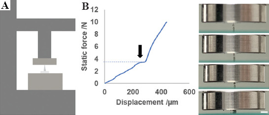
Mechanical strength testing of HMNs. (A) Schematic diagrams of mechanical strength testing of an HMN. (B) Force-displacement curve of a single HMN subjected to a compressive force of 2.5 N/min, and pictures for the deformation process of the HMN during compression tests (Scale bar: 1 mm).
3.4. Puncture experiment and skin healing experiment on mouse skin
Good puncture ability is critical for the microneedles to pierce stratum corneum and to assess the efficacy of transdermal drug delivery. As shown in Figure 7A, HMNPs efficiently penetrated the skin of mice, as evidenced by the H&E staining of tissue section with a puncture depth of about 300 μm. The pores formed by HMNs facilitated drug injection. After puncture, the skin barrier should be restored to avoid infection and other adverse reactions. Figure 7B showed that the micropore array on the surface of the mouse skin could be seen by naked eyes, and the shape was just the same as that of the HMNP. Then, the micropores gradually disappeared after HMNPs removal. After 120 min, the skin almost completely recovered, indicating that the skin could heal from HMNP insertion. These results show that HMNPs can be used for drug injection in a minimally invasive way.
Figure 7.

Puncture experiment and skin healing experiment. (A) Hematoxylin-eosin-stained cross-section of inserted skin by HMNs (Scale bar: 50 μm). (B) Skin healing images at 0 min, 10 min, 20 min, 30 min, 60 min, and 120 min after the HMNP treatment (Scale bar: 500 μm).
3.5. Preparation of HMN syringes
Many drugs need to be injected subcutaneously/intracutaneously to exert their effects. HMN syringes transdermally deliver drugs in minimally invasive and painless way, showing notable advantages due to the convenient quantitative delivery. In this study, HMNPs with holes at the bottom (Figure 3C) were used to manufacture HMN syringes for efficient and convenient drug delivery. The HMN syringe was assembled according to the schematic diagram shown in Figure 8A. An HMN syringe consists of an HMNP, a 3D printed converter and a micro-syringe. After assembly, an actual picture of the HMN syringe is shown in Figure 8B, which was a small, portable microinjection device. Based on the range and scale of syringe, injection volume and injection precision of HMN syringe can be determined, such as 0 – 10 ml, 0 – 25 ml, 0 – 50 ml, etc.
Figure 8.
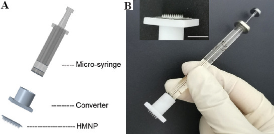
Preparation of the HMN syringe. (A) Schematic diagram for assembly of an HMN syringe. (B) An actual picture of an HMN syringe (Scale bar: 500 μm).
3.6. Delivery ability of HMN syringes in vitro
The drug delivery ability of HMN syringes needs to be first verified in vitro. Agarose gel is commonly used to simulate skin in vitro. It is a homogeneous and semi-clear material that enables the observation of the drug delivery process with an optical microscope[27]. Rhodamine is often used as a model drug for microneedle delivery. The results of multiple intermittent photographs within 0 – 1 min showed that rhodamine gradually diffused along the injection site within the agarose gel while an HMN syringe was used to perform injection (Figure 9). These results indicate that HMN syringes can be used for drug delivery.
Figure 9.
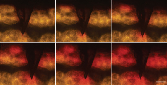
Delivery process of rhodamine into agarose gel by the HMN syringe (Scale bar: 200 μm).
3.7. Blood glucose control study in type 1 diabetic mice
People with Type 1 diabetes must inject insulin to control blood glucose. The long insulin needle causes huge physical and psychological pain to the patient. Therefore, repeated injection always causes poor compliance and unsatisfactory glycemic control. A portable HMN syringe is found to be useful for quantitative, minimally invasive, painless, and user-friendly injection, which can ease diabetic patients from needle phobia under traditional subcutaneous injection of insulin, thus improving their life quality.
In this study, our HMN syringes were used to deliver insulin for regulating blood glucose levels in diabetic mice. First, diabetic mice were successfully induced after STZ administration. The initial blood glucose level was 23 ± 5 mmol/L. Diabetic mice were then randomly divided into three groups. Diabetic mice in the commercial insulin syringe and HMN syringe group were treated with insulin (2 IU/kg). Their schematic representations of insulin injection are shown in Figure 10A and B. Commercial insulin needles often penetrate deep into the body, which often irritates nerves and causes pain. While the HMN with micron needles only penetrate the superficial layer of skin, which holds the advantages of minimal invasiveness and painlessness. The regulation of blood glucose levels detected at the time points of 0, 0.5, 1, 2, 4 h in the untreated group, commercial insulin syringe, and HMN syringe group are shown in Figure 10C. The reduction in blood glucose level in the HMN syringe group was similar to that in the commercial insulin syringe group. There was no obvious improvement in blood glucose levels in the untreated group, and the slight increase in 0.5 h might be due to stress response caused by blood sampling for monitoring blood glucose. The results indicate that the HMN syringe can be used for insulin injection to control blood glucose levels in a quantitative, minimally invasive, painless, and user-friendly way, which is beneficial for blood glucose management.
Figure 10.

Blood glucose control study in type 1 diabetic mice. (A) Schematic representation of insulin injection via commercial insulin syringe. (B) Schematic representation of insulin injection via HMN syringe. (C) Comparative blood glucose levels versus time (at time point of 0, 0.5, 1, 2, 4 h) for the untreated group, commercial insulin syringe and HMN syringe group applied to diabetic mice (n = 5).
4. Discussion
Currently, HMNs have been used for drug delivery in four main forms, that is, coated HMNs with drug-impregnated outer surface and inner cavity[29], HMN-based patch-like drug delivery system combining HMNP with drug reservoir[32], microinjection devices with a complex auxiliary injection device[5,7,8,33], and HMN syringe connecting HMN with a syringe[34-36]. However, coated HMNs are similar to commonly coated microneedles and hardly enable quantitative drug delivery. HMN-based patch-like drug delivery system and microinjection devices suffer from the limitation of complicated preparation and difficulty in drug dosage control. Microinjection devices need to connect the HMNs with a MEMS and injection device; therefore, the entire device has a large volume and is not conducive to portable use. In comparison, HMN syringe holds obvious advantages in the convenient quantitative delivery of drugs without complicated devices. HMN syringes have been effectively used for transdermal delivery of insulin[5,6,34,37], vaccines[7,38], immune checkpoint blockers[39], gene drugs[36], phenylephrine[40], etc. In addition, it is worth noted that HMNs are only suitable for local and small-dose drug delivery. Therefore, the insertion site and dosage of the drug administration should be carefully considered when exploiting the application of HMNs.
In this study, SOPL technology customizes an HMNP in seconds, which is the fastest speed for fabricating HMNPs at present. Meanwhile, the obtained HMNs have a smooth surface without layer-by-layer structure, improving the quality of 3D-printed HMNs. Despite the unprecedented progress in 3D printing of HMNPs, there are still several hurdles in this technology. First, because of the one-step photopolymerization of SOPL, it may be difficult to make microneedles with particularly complex structures, such as hollow surgical microneedle[41]. Second, only photopolymeric materials with certain transparency are available for preparing 3D-printed HMNPs. Third, most photopolymeric materials cannot meet the requirement of fabricating HMNs with good mechanical properties. Therefore, there is an urgent need to develop photopolymer materials with high strength, high toughness and high transparency. Finally, complicated post-treatment processes are required for the resultant HMNPs, including washing to remove residual materials, secondary photocuring to enhance HMNs and soaking into alcohol to improve biocompatibility, etc. The issue of complex post-processing can also be solved by exploiting new materials with better properties. Collectively, SOPL, a compelling and suitable approach, overcomes the limitations of speed, volume, and quality in HMNP fabrication. With the development of materials and technology, SOPL technology could promote the effective clinical translation and commercialization of HMNP.
5. Conclusions
In summary, this study innovatively used SOPL technology for fast customization of HMNPs with high quality. An HMNP could be obtained by one-step photopolymerization within 5 s. The obtained HMNs had good biocompatibility, mechanical properties, and puncture performance. After being equipped with syringes, HMNPs could be used for minimally invasive and painless injection of insulin to control blood glucose levels. Collectively, SOPL technology is expected to provide technical support for the mass production of HMNPs and promote their widespread clinical application.
Acknowledgments
We thank H. Wang from the Analytical and Testing Center, Sichuan University, P. R. China for the SEM observation and analysis of the data. We thank Zhiyuan Gou for his help in the preparation of the HMN syringe. We also thank Xide Dai for his work in the simulation video for the visualization of the HMN formation process.
Funding
This research was funded by National Key Research and Development Program of China (2021YFF1200800), Sichuan Innovative Research Team Program for Young Scientists (2021JDTD0001), 1·3·5 project for disciplines of excellence, West China Hospital, Sichuan University (ZYJC18017, ZYYC08007).
Conflict of interest
No conflict of interest was reported by all authors.
Author contributions
The manuscript was written through contributions of all authors. All authors have given approval to the final version of the manuscript. M.G. and Xian.J. designed and supervised the project. R.L., X.L., and B.L. contributed to experiment design and results. R.L., X.L., X.Y., S.W., L.L., Xue.J. and B.L. performed experiments. R.L., X.J., X.Y., S.W., L.L. and Xue.J. wrote the manuscript.
References
- 1.Gao B, Guo M, Lyu K, et al. Intelligent Silk Fibroin Based Microneedle Dressing (i-SMD) Adv Funct Mater. 2021;31:2006839. http://doi.org/10.1002/adfm.202006839. [Google Scholar]
- 2.Li X, Huang X, Mo J, et al. A Fully Integrated Closed-Loop System Based on Mesoporous Microneedles-Iontophoresis for Diabetes Treatment. Adv Sci (Weinh) 2021;8:e2100827. doi: 10.1002/advs.202100827. http://doi.org/10.1002/advs.202100827. [DOI] [PMC free article] [PubMed] [Google Scholar]
- 3.Yao S, Wang Y, Chi J, et al. Porous MOF Microneedle Array Patch with Photothermal Responsive Nitric Oxide Delivery for Wound Healing. Adv Sci (Weinh) 2021;9:e2103449. doi: 10.1002/advs.202103449. http://doi.org/10.1002/advs.202103449. [DOI] [PMC free article] [PubMed] [Google Scholar]
- 4.Sadeqi A, Kiaee G, Zeng W, et al. Hard Polymeric Porous Microneedles on Stretchable Substrate for Transdermal Drug Delivery. Sci Rep. 2022;12:1853. doi: 10.1038/s41598-022-05912-6. http://doi.org/10.1038/s41598-022-05912-6. [DOI] [PMC free article] [PubMed] [Google Scholar]
- 5.Economidou SN, Uddin MJ, Marques MJ, et al. A Novel 3D Printed Hollow Microneedle Microelectromechanical System for Controlled, Personalized Transdermal Drug Delivery. Addit Manuf. 2021;38:101815. http://doi.org/10.1016/j.addma.2020.101815. [Google Scholar]
- 6.Mishra R, Maiti TK, Bhattacharyya TK. Feasibility Studies on Nafion Membrane Actuated Micropump Integrated With Hollow Microneedles for Insulin Delivery Device. J Microelectromech Syst. 2019;28:987–96. http://doi.org/10.1109/Jmems.2019.2939189. [Google Scholar]
- 7.Niu L, Chu LY, Burton SA, et al. Intradermal Delivery of Vaccine Nanoparticles Using Hollow Microneedle Array Generates Enhanced and Balanced Immune Response. J. Control Release. 2019;294:268–78. doi: 10.1016/j.jconrel.2018.12.026. http://doi.org/10.1016/j.jconrel.2018.12.026. [DOI] [PubMed] [Google Scholar]
- 8.van der Maaden K, Heuts J, Camps M, et al. Hollow Microneedle-mediated Micro-injections of a Liposomal HPV E743-63 Synthetic Long Peptide Vaccine for Efficient Induction of Cytotoxic and T-helper Responses. J Control Release. 2018;269:347–54. doi: 10.1016/j.jconrel.2017.11.035. http://doi.org/10.1016/j.jconrel.2017.11.035. [DOI] [PubMed] [Google Scholar]
- 9.Gupta J, Denson DD, Felner EI, et al. Rapid Local Anesthesia in Humans Using Minimally Invasive Microneedles. Clin J Pain. 2012;28:129–35. doi: 10.1097/AJP.0b013e318225dbe9. http://doi.org/10.1097/AJP.0b013e318225dbe9. [DOI] [PMC free article] [PubMed] [Google Scholar]
- 10.Dardano P, De Martino S, Battisti M, et al. One-Shot Fabrication of Polymeric Hollow Microneedles by Standard Photolithography. Polymers (Basel) 2021;13:520. doi: 10.3390/polym13040520. http://doi.org/10.3390/polym13040520. [DOI] [PMC free article] [PubMed] [Google Scholar]
- 11.Wang PC, Wester BA, Rajaraman S, et al. Hollow Polymer Microneedle Array Fabricated by Photolithography Process Combined with Micromolding Technique. Annu Int Conf IEEE Eng Med Biol Soc. 20092009:7026–9. doi: 10.1109/IEMBS.2009.5333317. http://doi.org/10.1109/IEMBS.2009.5333317. [DOI] [PMC free article] [PubMed] [Google Scholar]
- 12.Bolton CJ, Howells O, Blayney GJ, et al. Hollow Silicon Microneedle Fabrication Using Advanced Plasma Etch Technologies for Applications in Transdermal Drug Delivery. Lab Chip. 2020;20:2788–95. doi: 10.1039/d0lc00567c. http://doi.org/10.1039/d0lc00567c. [DOI] [PubMed] [Google Scholar]
- 13.Li Y, Zhang H, Yang R, et al. Fabrication of Sharp Silicon Hollow Microneedles by Deep-reactive Ion Etching Towards Minimally Invasive Diagnostics. Microsyst Nanoeng. 2019;5:41. doi: 10.1038/s41378-019-0077-y. http://doi.org/10.1038/s41378-019-0077-y. [DOI] [PMC free article] [PubMed] [Google Scholar]
- 14.Trautmann A, Roth GL, Nujiqi B, et al. Towards a Versatile Point-of-care System Combining Femtosecond Laser Generated Microfluidic Channels And Direct Laser Written Microneedle Arrays. Microsyst Nanoeng. 2019;5:6. doi: 10.1038/s41378-019-0046-5. http://doi.org/10.1038/s41378-019-0046-5. [DOI] [PMC free article] [PubMed] [Google Scholar]
- 15.Carcamo-Martinez A, Mallon B, Dominguez-Robles J, et al. Hollow Microneedles:A Perspective in Biomedical Applications. Int J Pharm. 2021;599:120455. doi: 10.1016/j.ijpharm.2021.120455. http://doi.org/10.1016/j.ijpharm.2021.120455. [DOI] [PubMed] [Google Scholar]
- 16.Xenikakis I, Tsongas K, Tzimtzimis EK, et al. Fabrication of Hollow Microneedles Using Liquid Crystal Display (LCD) Vat Polymerization 3D Printing Technology for Transdermal Macromolecular Delivery. Int J Pharm. 2021;597:120303. doi: 10.1016/j.ijpharm.2021.120303. http://doi.org/10.1016/j.ijpharm.2021.120303. [DOI] [PubMed] [Google Scholar]
- 17.Yeung C, Chen S, King B, et al. A 3D-Printed Microfluidic-enabled Hollow Microneedle Architecture for Transdermal Drug Delivery. Biomicrofluidics. 2019;13:064125. doi: 10.1063/1.5127778. http://doi.org/10.1063/1.5127778. [DOI] [PMC free article] [PubMed] [Google Scholar]
- 18.Ovsianikov BC, Mente P, Monteiro-Riviere NA, et al. Two Photon Polymerization of Polymer–Ceramic Hybrid Materials for Transdermal Drug Delivery. Int J Appl Ceram Technol. 2007;4:22–9. http://doi.org/10.1111/j.1744-7402.2007.02115.x. [Google Scholar]
- 19.Mathew E, Pitzanti G, Dos Santos AL, et al. Optimization of Printing Parameters for Digital Light Processing 3D Printing of Hollow Microneedle Arrays. Pharmaceutics. 2021;13:1837. doi: 10.3390/pharmaceutics13111837. http://doi.org/10.3390/pharmaceutics13111837. [DOI] [PMC free article] [PubMed] [Google Scholar]
- 20.Liao C, Anderson W, Antaw F, et al. Two-Photon Nanolithography of Tailored Hollow three-dimensional Microdevices for Biosystems. ACS Omega. 2019;4:1401–9. doi: 10.1021/acsomega.8b03164. http://doi.org/10.1021/acsomega.8b03164. [DOI] [PMC free article] [PubMed] [Google Scholar]
- 21.Doraiswamy A, Ovsianikov A, Gittard SD, et al. Fabrication of Microneedles Using Two Photon Polymerization for Transdermal Delivery of Nanomaterials. J Nanosci Nanotechnol. 2010;10:6305–12. doi: 10.1166/jnn.2010.2636. http://doi.org/10.1166/jnn.2010.2636. [DOI] [PubMed] [Google Scholar]
- 22.Liu X, Li R, Yuan X, et al. Fast Customization of Microneedle Arrays by Static Optical Projection Lithography. ACS Appl Mater Interfaces. 2021;13:60522–30. doi: 10.1021/acsami.1c21489. http://doi.org/10.1021/acsami.1c21489. [DOI] [PubMed] [Google Scholar]
- 23.Tan JY, Kim A, Kim JJ. Modeling, Characterization, and Fabrication of Bell-tip Microneedle Array by Diffraction and Self-aligned Lens Effects. Appl Phys Lett. 2021;119:023501. http://doi.org/10.1063/5.0055073. [Google Scholar]
- 24.Yang C, Yu Y, Wang X, et al. Cellular Fluidic-based Vascular Networks for Tissue Engineering. Eng Regen. 2021;2:171–4. http://doi.org/10.1016/j.engreg.2021.09.006. [Google Scholar]
- 25.Use of International Standard ISO-10993-1. Biological Evaluation of Medical Devices Part 1:Evaluation and Testing within a Risk Management Process. US Department of Health and Human Services FDA, Center for Devices and Radiological Health, Center for Biologics Evaluation and Research 2020 [Google Scholar]
- 26.Lim SH, Tiew WJ, Zhang J, et al. Geometrical Optimisation of a Personalised Microneedle Eye Patch for Transdermal Delivery of Anti-wrinkle Small Peptide. Biofabrication. 2020;12:035003. doi: 10.1088/1758-5090/ab6d37. http://doi.org/10.1088/1758-5090/ab6d37. [DOI] [PubMed] [Google Scholar]
- 27.Zhang D, Das DB, Rielly CD. Microneedle Assisted Micro-Particle Delivery from Gene Guns:Experiments Using Skin-Mimicking Agarose Gel. J Pharm Sci. 2014;103:613–27. doi: 10.1002/jps.23835. http://doi.org/10.1002/jps.23835. [DOI] [PubMed] [Google Scholar]
- 28.Wang J, Yu J, Zhang Y, et al. Charge-switchable Polymeric Complex for Glucose-responsive Insulin Delivery in Mice and Pigs. Sci Adv. 2019;5:eaaw4357. doi: 10.1126/sciadv.aaw4357. http://doi.org/10.1126/sciadv.aaw4357. [DOI] [PMC free article] [PubMed] [Google Scholar]
- 29.Zhou C, Tang H, Zhang L, et al. Hollow Microneedle Arrays Produced by Low?Cost, High?Fidelity Replication of Hypodermic Needle Tips for High?Dose Transdermal Drug Delivery. Adv Eng Mater. 2021;23:2001355. http://doi.org/10.1002/adem.202001355. [Google Scholar]
- 30.Oskui SM, Diamante G, Liao C, et al. Assessing and Reducing the Toxicity of 3D-Printed Parts. Environ Sci Technol Lett. 2016;3:1–6. http://doi.org/10.1021/acs.estlett.5b00249. [Google Scholar]
- 31.Davis SP, Landis BJ, Adams ZH, et al. Insertion of Microneedles into Skin:Measurement and Prediction of Insertion Force and Needle Fracture Force. J Biomech. 2004;37:1155–63. doi: 10.1016/j.jbiomech.2003.12.010. http://doi.org/10.1016/j.jbiomech.2003.12.010. [DOI] [PubMed] [Google Scholar]
- 32.Roxhed N, Samel B, Nordquist L, et al. Painless Drug Delivery through Microneedle-based Transdermal Patches Featuring Active Infusion. IEEE Trans Biomed Eng. 2008;55:1063–71. doi: 10.1109/TBME.2007.906492. http://doi.org/10.1109/TBME.2007.906492. [DOI] [PubMed] [Google Scholar]
- 33.Burton SA, Ng CY, Simmers R, et al. Rapid Intradermal Delivery of Liquid Formulations Using a Hollow Microstructured Array. Pharm Res. 2011;28:31–40. doi: 10.1007/s11095-010-0177-8. http://doi.org/10.1007/s11095-010-0177-8. [DOI] [PMC free article] [PubMed] [Google Scholar]
- 34.Ma Y, Li CG, Kim S, et al. An Insulin Microneedle Pen (IMP) for Self-Subcutaneous Insulin Injection. Adv Mater Technol. 2018;3:1800234. http://doi.org/10.1002/admt.201800234. [Google Scholar]
- 35.Jung YS, Koo DH, Yang JY, et al. Peri-tumor Administration of 5-fluorouracil Sol-gel Using a Hollow Microneedle for Treatment of Gastric Cancer. Drug Deliv. 2018;25:872–9. doi: 10.1080/10717544.2018.1455760. http://doi.org/10.1080/10717544.2018.1455760. [DOI] [PMC free article] [PubMed] [Google Scholar]
- 36.Dul M, Stefanidou M, Porta P, et al. Hydrodynamic Gene Delivery in Human Skin Using a Hollow Microneedle Device. J Control Release. 2017;265:120–31. doi: 10.1016/j.jconrel.2017.02.028. http://doi.org/10.1016/j.jconrel.2017.02.028. [DOI] [PubMed] [Google Scholar]
- 37.Norman JJ, Brown MR, Raviele NA, et al. Faster Pharmacokinetics and Increased Patient Acceptance of Intradermal Insulin Delivery Using a Single Hollow Microneedle in Children and Adolescents with Type 1 Diabetes. Pediatr Diabetes. 2013;14:459–65. doi: 10.1111/pedi.12031. http://doi.org/10.1111/pedi.12031. [DOI] [PubMed] [Google Scholar]
- 38.Ogai N, Nonaka I, Toda Y, et al. Enhanced Immunity in Intradermal Vaccination by Novel Hollow Microneedles. Skin Res Technol. 2018;24:630–5. doi: 10.1111/srt.12576. http://doi.org/10.1111/srt.12576. [DOI] [PubMed] [Google Scholar]
- 39.Chen G, Chen Z, Wen D, et al. Transdermal Cold Atmospheric Plasma-mediated Immune Checkpoint Blockade Therapy. Proc Natl Acad Sci U S A. 2020;117:3687–92. doi: 10.1073/pnas.1917891117. http://doi.org/10.1073/pnas.1917891117. [DOI] [PMC free article] [PubMed] [Google Scholar]
- 40.Jun H, Han MR, Kang NG, et al. Use of Hollow Microneedles for Targeted Delivery of Phenylephrine to Treat Fecal Incontinence. J Control Release. 2015;207:1–6. doi: 10.1016/j.jconrel.2015.03.031. http://doi.org/10.1016/j.jconrel.2015.03.031. [DOI] [PubMed] [Google Scholar]
- 41.Szeto B, Aksit A, Valentini C, et al. Novel 3D-printed Hollow Microneedles Facilitate Safe, Reliable, and Informative Sampling of Perilymph from Guinea Pigs. Hear Res. 2020;400:108141. doi: 10.1016/j.heares.2020.108141. http://doi.org/10.1016/j.heares.2020.108141. [DOI] [PMC free article] [PubMed] [Google Scholar]
Associated Data
This section collects any data citations, data availability statements, or supplementary materials included in this article.


