

Abstract
This Letter reports ring-shaped photoacoustic (PA) tweezers that are capable of manipulating single or multiple micron-sized particles. By illuminating a thin layer of an optically absorptive liquid medium with a focused annular pulsed laser beam and a higher pulse repetition rate (e.g., 800 Hz), both acoustic radiation force and instantaneous vaporization repulsion are generated within a certain distance of the illumination region. This makes it possible to conduct continuous and versatile locomotion of single or multiple microparticles. In this Letter, interactions between two or more particles are demonstrated, such as separation, attachment, and grouping of microparticles. The PA tweezers combine some of the advantages of conventional optical and acoustic tweezers and are expected to be a useful alternative approach for the manipulation of microscale objects.
In recent years, optical and acoustic tweezers have gained significant attention for single-particle manipulation. Optical tweezers utilize the optical radiation force from a highly focused continuous wave laser beam to trap a single particle at the focal point [Fig. 1(a)] [1–4]. The optical radiation force is directly exerted on the surface of the target due to the exchange of momentum between the object and the light field. Because the laser beam can be tightly focused and easily steered, optical tweezers can provide high spatial resolution and excellent maneuverability of the particle in question. Nevertheless, optical tweezers can only function on targets that are either transparent or polarizable. In contrast, acoustic tweezers exploit standing or focused ultrasound waves to generate acoustic radiation forces (ARFs) that can trap single or multiple particles without the material-specific demands of optical tweezers [Fig. 1(b)] [5–8]. The ARF is generated on the surface of the target in the path of acoustic wave due to the apparent pressure difference between the target surface and its surrounding medium. However, the spatial resolution of acoustic tweezers is limited by the relatively long wavelengths of ultrasound waves. In addition, a physical contact is needed between the transducer and the liquid medium for acoustic coupling, which complicates the manipulation setup and operation process.
Fig. 1.

Three methods of single particle manipulation. (a) Optical tweezers. (b) Single-beam acoustic tweezers. (c) PA tweezers. OB, optical beam; OL, optical lens; ORF, optical radiation force; FUT, focused ultrasound transducer; ARF, acoustical radiation force; IVR, instantaneous vaporization repulsion. The black arrows, dotted arrows, and bold arrow show the directions of ORF, ARF, and IVR, respectively.
Previously, the photoacoustic (PA) effect has been investigated as an alternative approach for single particle manipulation [Fig. 1(c)] [9]. A focused short-pulsed laser beam is projected onto the surrounding liquid medium of the target. Upon optical absorption, the short-laser pulse is converted into a heat pulse, which can induce high-frequency ultrasound waves (i.e., PA waves) through a transient thermoelastic process. When the laser pulse energy is below the instantaneous vaporization threshold, only the ARF is generated from the (traveling) PA waves within a certain distance of the illumination spot. With higher pulse energy, instantaneous vaporization repulsion (IVR) [10] can also occur near the illumination spot, creating localized repulsive forces that can be much stronger than the ARF.
With optically generated PA waves, PA tweezers combine some of the advantages of their optical and acoustic counterparts, such as high spatial resolution, easy maneuverability, and versatility. Especially through using an annular pulsed laser beam for illumination (Fig. 2), an ARF field can be generated between the center and inner edge of the laser ring [9,11,12]. Although the initial concept has been demonstrated before, many technical aspects of ring-shaped PA tweezers have yet to be explored. For example, the optics for controlling the ring geometry has not been fully developed. In addition, PA manipulation has been conducted with single laser pulses or low pulse repetition rates (PRRs) (<20 Hz). As a result, only sporadic hopping motions of the manipulated particles have been obtained, and the particles could easily escape from the ring through the border. Furthermore, the manipulation with ring geometry has been solely based on the ARF and the application of the IVR and a combination of both IVR and ARF near the edge has not been explored. In this Letter, we explore the development of ring-shaped PA tweezers based on specially designed laser delivery optics with a much higher PRR. Continuous locomotion of microparticles with different sizes is achieved through dual action of ARF and IVR. Interactions between two or more particles, including separation, attachment, and grouping are also demonstrated.
Fig. 2.

Manipulations of microparticles by annular pulsed laser beam. The green ring geometry represents the annular laser beam. The dotted and bold arrows show the direction of forces due to ARF and IVR, respectively.
Figure 3 shows the experimental setup for the PA tweezers. A 532-nm Nd:YAG pulsed laser (ELFORLIGHT FQS-200-1-532, 4 ns pulse duration) is used as the light source. Its PRR is set to 800 Hz, which is the highest frequency at which it can maintain constant output pulse energy. The pulsed laser generates a collimated beam with a diameter of 3 mm, which is expanded to 15 mm by a pair of lenses (L1 and L2) and filtered by a pinhole (PH). An axicon (AX1) converts the beam into a Bessel beam, which is a cone of collimated annular beam. With a focusing lens (L3), the cone is converted into a focused ring. The diameter of the ring is controlled by the distance between the two axicons (AX2 and AX3). AX2 is mounted on a motorized stage to adjust the distance. The ring radius (r1) of the beam after AX3 can be given as r1 = d tan(4.7°) − r0, where r0 is the beam radius before AX2, and d is the distance between AX2 and AX3. After being reflected by a mirror (M1) and a dichroic mirror (DM), the ring is imaged onto the sample plate (SP) by a 20× objective lens (OL1). The thickness of the laser ring is determined by the ring diameter before OL1 and the magnification ratio of OL1. The SP is illuminated by a white light beam through the DM and monitored by a CMOS camera through a second objective lens (OL2), a convex lens (L4), and an attenuator (AT). The SP consists of two cover glasses with a thickness of 0.1 mm and a vinyl spacer with a thickness of ~15 μm. A layer of phenol red (PR) dye solution (0.1% concentration) containing polystyrene beads is added between the two cover glasses. In practice, the actual thickness of the liquid layer could range between 15 μm and 30 μm.
Fig. 3.

Optical setup for the ring-shaped PA tweezers. L1–L4, lenses (focal length f1 = 5 cm, f2 = 25 cm, f3 = 10 cm, f4 = 15 cm); PH, pinhole; AX1–AX3, axicons (deflection angle 4.7°); DM, dichroic mirror; WL, white light; OL1–OL2, objective lenses (20×, NA = 0.4); SP, sample plate; M1–M2, mirrors; AT, attenuator; VS, vinyl spacer; CG1–CG2, cover glasses; LB, laser beam; PB, polystyrene beads; PR, phenol red.
There are several factors that determine the amplitude of the PA-generated ARF and IVR, including laser pulse energy, ring diameter, dye concentration, and ring thickness. Among them, bead size is able to affect the threshold of laser pulse energy for ARF, while its effect on IVR is much less impactful. Therefore, three representative cases are characterized, including ARF on 8-μm and 15-μm polystyrene beads and IVR on 15-μm beads. The threshold of laser pulse energy (of the whole annular beam with different ring diameters) for moving beads in the PR dye solution with different concentrations (50%, 67%, 80%) are characterized. The polystyrene beads are suspended in a mixture of the sodium azide solution (where the polystyrene beads are stored) and PR solution. The concentration of PR is controlled by the volume ratio of PR solution to total volume. With transmission testing, the absorption coefficients of the three concentrations (50%, 67%, and 80%) for a 20-μm-thick liquid layer are determined to be 66/cm, 131/cm, and 195/cm, respectively. Figure 4 shows the threshold pulse energy for moving the 8-μm beads with the ARF at the inner edge of the annular beam. Higher pulse energy is needed for lower-concentration solutions, because the amplitude of the PA wave is nearly proportional to the local optical fluence and the absorber concentration [12]. Figure 5 shows the threshold pulse energy for moving the 15-μm beads with the ARF near the inner edge of the ring. The thresholds are typically 5 – 10 μJ higher than those using ARF on 8-μm beads. Figure 6 shows the threshold pulse energy for moving the 15-μm beads with IVR near the inner edge. The threshold is 15–20 μJ higher than that using ARF and also increases almost linearly with the ring diameter. Based on the testing results, the threshold of ARF on 8-μm beads and 15-μm beads, and IVR on 15-μm beads are estimated as Pt = 0.49r/C − 0.85, Pt = 0.44r/C + 4.70, and Pt = 0.28r/C+24.43, respectively, where Pt is the threshold pulse energy in μJ, r is a certain ring radius in μm, and C is the dye concentration. Because the illumination area increases linearly with the ring diameter, when the ring diameter increases, a higher pulse energy will be needed to maintain the optical intensity density. The minimum optical intensity for (1) ARF to move 8-μm beads, (2) ARF to move 15-μm beads, and (3) IVR to move 15-μm beads is estimated to be ~2.3 × 10⁷ J/(cm2 s), ~ 2.9 × 10⁷ J/(cm2 s), and ~6.1 × 10⁷ J/(cm2 s), respectively. It is also observed that with an even higher pulse energy (over twice the threshold pulse energy), visible micro bubbles appear. The expansion and contraction during the formation of micro bubbles create additional repulsive or attracting forces, making the particle motion uncontrollable. Therefore, it is necessary to set up ceiling pulse energies for the manipulations.
Fig. 4.

Threshold of laser pulse energy for ARF to move 8-μm polystyrene beads.
Fig. 5.

Threshold of laser pulse energy for ARF to move 15-μm polystyrene beads.
Fig. 6.

Threshold of laser pulse energy for IVR to move 15-μm polystyrene beads.
With the optical setup, different manipulation schemes, such as single particle manipulation and grouping or separating multiple particles are demonstrated. Figures 7(a)–7(c) (see Visualization 1) show the manipulation of an 8-μm polystyrene bead by IVR (ring diameter 90 μm, pulse energy 55 μJ). Figures 7(d)–7(f) (see Visualization 2) show a similar manipulation with a 15-μm bead (85 μm, 50 μJ). The beads move with the laser ring at an average velocity of ~5 μm/s. The velocity of particle movement with IVR is controlled by the movement of the laser ring, which can reach up to 30 μm/s when the particles are enclosed inside the laser ring. Figures 8(a)–8(c) (see Visualization 3) show the manipulation of an 8-μm bead with ARF (100 μm, 40 μJ). The laser ring remains still, and the particle is pushed by ARF at an average velocity of ~0.7 μm/s. Figures 8(d)–8(f) (see Visualization 4) show the manipulation of a 15-μm bead with ARF (105 μm, 43 μJ). The bead inside is pushed upward by the static ring at a velocity of ~1 μm/s. Furthermore, the particles can also be pushed by the outer edge of the ring with a velocity as high as 20 μm/s. According to Stokes’ law [13], the maximum time-averaged force due to the ARF on a particle is estimated to be around 1 pN, while the instantaneous forces of IVR should be of the order of μNs [9].
Fig. 7.

Single particle manipulation with IVR: (a)–(c) 8-μm polystyrene bead; (d)–(f) 15-μm polystyrene bead. (See Visualization 1 and Visualization 2.) The white arrows indicate the particle’s direction of movement. The static particles marked with a dashed circle serve as a reference for location.
Fig. 8.

Single particle manipulation with ARF: (a)–(c) 8-μm bead; (d)–(f) 15-μm bead. (See Visualization 3 and Visualization 4.)
Figures 9(a)–9(c) (see Visualization 5) show the attachment of two 15-μm beads inside the laser ring. The ring diameter is 90 μm and the pulse energy is 55 μJ. With the IVR near the inner edge, the particle on the right is moved toward the particle on the left at an average velocity of ~6 μm/s. If the two particles are separated by a distance larger than the ring diameter, the particles can be brought closer together first (by moving one particle as shown in Figs. 7 and 8), and then attached to each other. Figures 9(d)–9(f) (see Visualization 6) show the process of two particles detaching from each other. The ring diameter remains 90 μm and the pulse energy is 55 μJ. The right-hand particle is pushed away at a velocity of ~6 μm/s by the IVR near the outer edge of the laser ring while the left-hand one remains almost still within the ring. It should be noted that the static particle could have slight motion caused by ARFs; however, this motion is much slower than that of the moving particle pushed by IVR and, therefore, can be neglected.
Fig. 9.
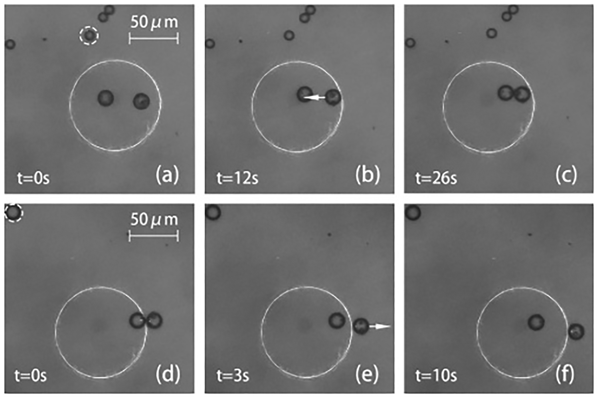
Manipulation of two particles. (a)–(c) One particle being moved toward the other. (d)–(f) One particle being moved away from the other. (See Visualization 5 and Visualization 6.)
Particle manipulation can also be conducted by changing the ring diameter. Figure 10 (see Visualization 7) shows the grouping of multiple beads by gradually shrinking the laser ring. AX2 is gradually moved toward AX3 to decrease the ring diameter from 126 μm to 90 μm. The pulse energy of the whole ring is kept at 50 μJ. The six 8-μm-diameter beads trapped inside the ring are pushed towards each other by the ARF with a velocity of ~0.5 μm/s [Figs. 10(a)–10(d)]. Next, the ring is shifted to the right to make small adjustments and to finally complete the attachment of the six particles [Figs. 10(e) and 10(f)].
Fig. 10.

Grouping of six particles with size-changing laser ring. (a)–(d) Grouping done by decreasing the ring diameter. (e), (f) Attachment of six particles. (See Visualization 7.)
The PA manipulation operations are affected by several factors. The acoustic forces generated by the PA effect are short pulses. As long as the required pulse energy can be maintained, increasing the PRR helps to create stronger effective forces and a more continuous and controllable motion of the manipulated particles. The thickness of the liquid layer also affects particle entrapment. With larger thickness, the movements of particles will become less stable due to the occurrence of acoustic streaming. The uniformity of the annular beam is also critical. With a non-uniform ring, the particle may escape more easily from the section with lower optical fluence.
In conclusion, this Letter demonstrates ring-shaped PA tweezers with a higher PRR, which are capable of the manipulation of single or multiple particles in a highly controllable manner. So far, the functionality of the PA tweezers requires the addition of dyes to excite the PA waves, which could be made unnecessary by using sample plates with desirable optical absorption properties. Without the need of direct optical illumination onto the target, the PA tweezers could be as biocompatible as conventional acoustic tweezers and, therefore, could be useful for the manipulation of single cells, which will be investigated in future studies.
Supplementary Material
Acknowledgment.
The authors thank Mr. Logan Lu for proofreading the manuscript.
Funding.
National Institutes of Health (R01GM141055, U18TR003778, UG3TR002978); National Science Foundation (ECCS-1807601, ECCS-1809710).
Footnotes
Disclosures. T.J.H. has co-founded a company, Ascent Bio-Nano Technologies Inc., to commercialize acoustofluidics and acoustic tweezers technologies; however, this company does not support this work.
Data availability.
Data underlying the results presented in this paper are not publicly available at this time but may be obtained from the authors upon reasonable request.
REFERENCES
- 1.Schonbrun E, Piestun R, Jordan P, Cooper J, Wulff KD, Courtial J, and Padgett M, Opt. Express 13, 3777 (2005). [DOI] [PubMed] [Google Scholar]
- 2.Shao B, Song D, Zlatanovic S, Esener SC, Vinson J, Botvinick EL, and Berns MW, in 2005. OSA Topical Meeting on Information Photonics, Charlotte, North Carolina, June 6, 2005, 1. [Google Scholar]
- 3.Zhao Q, Wang H, Yu P, Zhang S, Zhou J, Li Y, and Gong L, Front. Bioeng. Biotechnol 8, 422 (2020). [DOI] [PMC free article] [PubMed] [Google Scholar]
- 4.Lei M, Li Z, Yan S, Yao B, Qi Y, Qian J, Yang Y, Gao P, and Ye T, PLoS One 8, e57984 (2013). [DOI] [PMC free article] [PubMed] [Google Scholar]
- 5.Wu J, J. Acoust. Soc. Am 89, 2140 (1991). [DOI] [PubMed] [Google Scholar]
- 6.Ding X, Lin SS, Kiraly B, Yue H, Li S, Chiang I, Shi J, Benkovic SJ, and Huang TJ, Proc. Natl. Acad. Sci 109, 11105 (2012). [DOI] [PMC free article] [PubMed] [Google Scholar]
- 7.Lee J, Teh SY, Lee A, Kim HH, Lee C, and Shung KK, Appl. Phys. Lett 95, 073701 (2009). [DOI] [PMC free article] [PubMed] [Google Scholar]
- 8.Lam K, Li Y, Li Y, Lim HG, Zhou Q, and Shung KK, Sci. Rep 6, 37554 (2016). [DOI] [PMC free article] [PubMed] [Google Scholar]
- 9.Zharov VP, Malinsky TV, and Kurten RC, J. Phys. D: Appl. Phys 38, 2662 (2005). [Google Scholar]
- 10.Lyamshev LM, Sov. Phys. Usp 24, 977 (1981). [Google Scholar]
- 11.Gorkov LP, Sov. Phys. Dokl 6, 773 (1962). [Google Scholar]
- 12.Wang Q, Riaud A, Zhou J, Gong Z, and Baudoin M, Phys. Rev. Appl 15, 044034 (2021). [Google Scholar]
- 13.Pesce G, Jones P, Marago O, and Volpe G, Eur. Phys. J. Plus 135, 949 (2020). [Google Scholar]
Associated Data
This section collects any data citations, data availability statements, or supplementary materials included in this article.
Supplementary Materials
Data Availability Statement
Data underlying the results presented in this paper are not publicly available at this time but may be obtained from the authors upon reasonable request.