

Abstract
Powered prostheses can enable individuals with above-knee amputations to ascend stairs step-over-step. To accomplish this task, available stair ascent controllers impose a pre-defined joint impedance behavior or follow a pre-programmed position trajectory. These control approaches have proved successful in the laboratory. However, they are not robust to changes in stair height or cadence, which is essential for real-world ambulation. Here we present an adaptive stair ascent controller that enables individuals with above-knee amputations to climb stairs of varying stair heights at their preferred cadence and with their preferred gait pattern. We found that modulating the prosthesis knee and ankle position as a function of the user’s thigh in swing provides toe clearance for varying stair heights. In stance, modulating the torque-angle relationship as a function of the prosthesis knee position at foot contact provides sufficient torque assistance for climbing stairs of different heights. Furthermore, the proposed controller enables individuals to climb stairs at their preferred cadence and gait pattern, such as step-by-step, step-over-step, and two-steps. The proposed adaptive stair controller may improve the robustness of powered prostheses to environmental and human variance, enabling powered prostheses to more easily move from the lab to the real-world.
Index Terms—: Robotic Leg, Prosthesis, Powered Prosthetics, Amputation, Gait, Biomechanics
Video Abstract
I. Introduction
CONVENTIONAL knee and ankle prostheses cannot provide net-positive energy [1], which is necessary to propel the body forward and upward during ambulation [2]. Additionally, they cannot actively control the joint movements, which is critical, for example, to achieve toe clearance in swing [2]. While walking, individuals with an above-knee amputation make up for the deficiencies in their passive prostheses by performing undesirable compensatory movements with their residual limb, intact leg, and upper body [3]–[5]. Unfortunately, these compensatory movements are insufficient for most users to ascend stairs step-over-step [4]–[6]. As a result, individuals with a conventional passive prosthesis commonly ascend stairs using a slower and less efficient step-by-step gait pattern, leading each step with their intact leg [4]–[6]. With this step-by-step pattern, the intact leg and upper body perform all the effort required to climb the step, which requires significant strength and endurance [3], [7]. Moreover, the residual limb hip joint needs to extend and circumduct unnaturally for the passive prosthesis to clear the step during swing as the prosthetic knee joint cannot flex as the biological leg would [8]. This residual limb extension is often difficult due to muscle contractures [9] further challenging the user’s balance [10]. Improved prosthesis technologies are needed to enable individuals with above-knee amputations to ascend stairs more naturally.
Powered prostheses [11] have the potential to imitate the biological leg biomechanics during stair ascent [12], [13]. A powered prosthesis can propel the body upward by injecting positive energy when the prosthetic foot is in contact with the step (i.e., stance phase). Also, a powered prosthesis can ensure adequate clearance with the step and correctly place the prosthetic foot in preparation for the next step to be climbed by actively controlling the joint movements when the prosthetic foot is off the ground (i.e., swing phase). Because climbing taller stairs requires larger net-positive energy and higher joint torque than climbing smaller stairs [12], the torque generated by the prosthesis in stance phase must be adapted to the stair height. In addition, different stair heights or variations in gait patterns require the prosthesis to change the swing movement trajectory so that proper clearance and foot placement on the step can be achieved. Thus, powered prosthesis controllers must be robust to variability in stair geometry, gait pattern, and gait cadence to enable ascending stairs in the real world.
Experimental studies have shown that powered prostheses can enable individuals with an above-knee amputation to ascend stairs step-over-step [14]–[22] resulting in improved stair ambulation speed and reduced metabolic effort compared to using a conventional passive prosthesis [19]. However, available stair ascent controllers are designed to produce a predefined, fixed action of the powered prosthesis [15], [17], which must be manually tuned for each subject and staircase [23]. Thus, if a user attempts to climb a taller step than the one the stair controller was tuned for, the prosthesis may not provide enough clearance, the prosthetic foot may hit the step riser, and the user may trip and fall. Even if the step is cleared by the user through hip circumduction and sound-side vaulting, the prosthetic foot may not lay flat on the step. So, when the prosthetic knee starts generating torque as necessary to climb the step, the subject may be pushed backward rather than upward, potentially causing the user to fall. Similarly, the amount of energy injected by the prosthesis when climbing the step may be too large or too small, if a shorter or taller step is taken compared to the tuning step. We need powered prosthesis controllers that automatically adapt to the variability of stair height encountered in the real world.
In this paper, we propose an alternative control strategy for a powered knee and ankle prosthesis to ascend stairs with varying stair heights, cadences, and gait patterns. Specifically, we propose modulating the prosthesis knee and ankle position in swing as a continuous function of the user’s thigh position, thigh velocity, and vertical acceleration of the prosthesis. In addition, we propose modulating energy injection in stance using a continuous adaptation of the knee joint torque-angle relationship as a function of the prosthesis knee position when the prosthetic foot contacts the step. Previous studies have proposed using the orientation of the residual limb as a proxy for the gait phase to produce a desired prosthesis trajectory in level-ground [24] and inclined walking [25]. In contrast, we propose changing the swing trajectory online during stair ambulation. We hypothesize that such a continuous modulation of stance energy and swing trajectory will enable individuals with above-knee amputations to climb stairs of different heights at different cadences and to seamlessly transition between different stair climbing strategies, such as step-by-step, step-over-step, and two-steps. We will test this hypothesis by asking an individual with a unilateral above-knee amputation to ascend stairs of different heights using different gait patterns at their self-selected speed. We expect a stair controller with these characteristics to facilitate translating powered prostheses to real-world use.
II. Adaptive Stair Controller
Biomechanical analysis of nonamputee subjects and pilot testing with the powered prostheses showed that the knee flexion angle increases with the hip flexion angle during swing, when the foot is off the ground. Moreover, faster hip flexion movements result in higher knee flexion angles. Preliminary analysis also showed that the hip joint does not initially flex during early swing, while the knee flexes. However, during early swing the residual hip joint (i.e., prosthesis side) moves vertically (without rotating), which allows the foot to clear the first step.
To capture the behavior of the biological leg, in Swing, we use a position controller that continuously adapts the desired angles of the knee joint and ankle joint based on the movements of the user’s thigh (i.e., residual limb). Specifically, the desired angle of the knee joint is defined as the sum of three terms determined as shown in (1–4) and graphically represented in Fig.1(a–d).
| (1) |
| (2) |
| (3) |
| (4) |
Fig.1. Swing Controller.
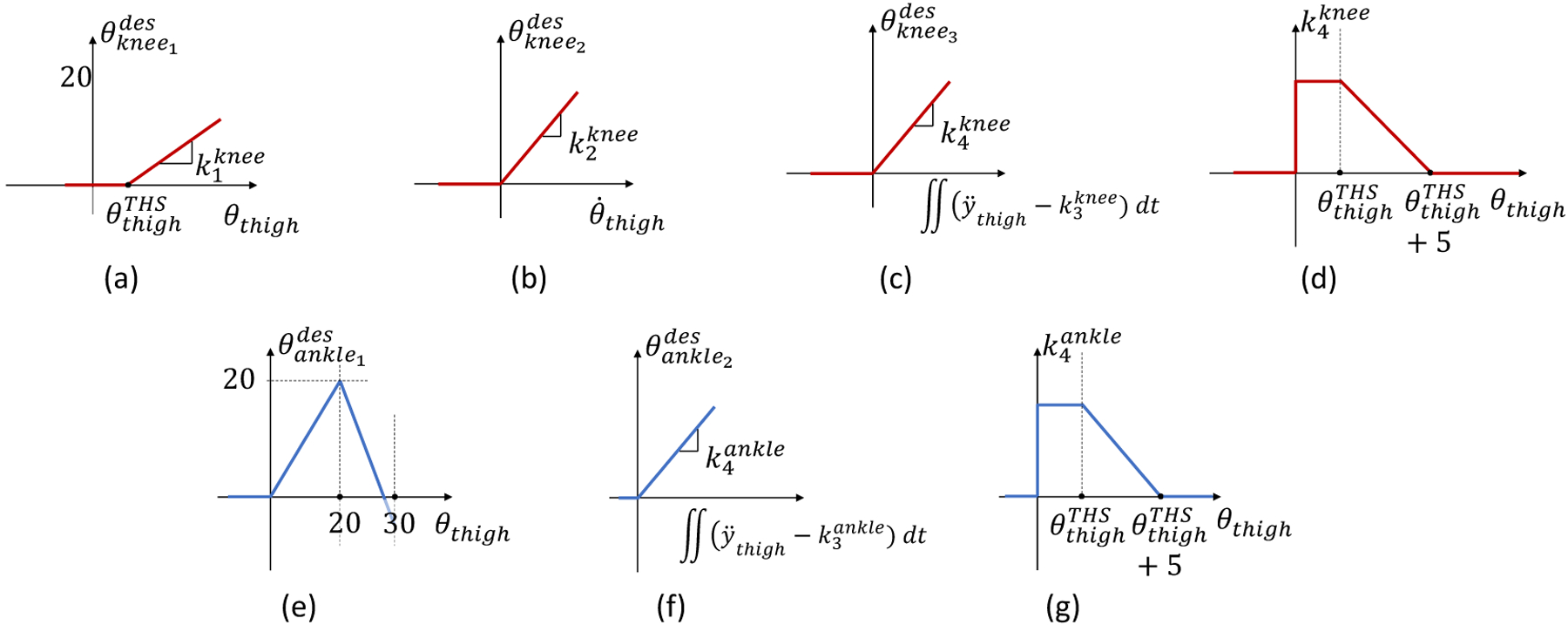
(a-d) Express the relationship between the thigh position (a), thigh velocity (b), and thigh vertical acceleration (c,d) for the powered prosthesis knee joint desired position. (e-g) Express the relationship between the thigh position (e), and thigh vertical acceleration (f,g) for the powered prosthesis ankle joint desired position.
The first term is proportional to the orientation of the user’s thigh with respect to gravity (θthigh) provided a predefined threshold is exceeded as defined in (1) and shown in Fig.1(a). The second term is proportional to the positive angular velocity of the user’s thigh as defined in (2) and shown Fig.1(b). Thus, using (1) and (2), the proposed Swing controller captures the dependency of the biological knee joint angle to the angle and velocity of the hip joint observed in nonamputee biomechanics.
The third term determining the desired knee position in Swing depends on the vertical acceleration of the user’s thigh with respect to gravity . As defined in (3) and shown in Fig.1(c) a constant is subtracted from the thigh acceleration before calculating the double integral. The result of the double integration is multiplied by a non-constant factor . This multiplication factor changes as a function of the thigh orientation (θthigh) as shown in (4) and Fig.1. (d). Specifically, the multiplication factor is kept constant until the thigh orientation (θthigh) exceeds a certain threshold . Above this thigh threshold, the multiplication factor decreases linearly, reaching zero when the thigh orientation equals the thigh threshold plus 5° , Fig.1(d). So, the multiplication factor works as a linear gain that decreases as the thigh orientation angle increases after a certain thigh threshold is exceeded. Thus, the proposed Swing controller captures the initial vertical movement of the hip and translates that movement into a desired flexion of the prosthesis knee joint as defined in (3) and (4). The prosthesis knee flexion resulting from (3–4) enables the prosthetic foot to clear the step in early swing.
The desired angular position of the ankle joint in Swing is the sum of two terms. The first term depends on the thigh position as defined in (5) and shown in Fig.1. (e). This term is zero for thigh angles lower than zero. When the thigh angle is between 0° and 20°, the desired ankle angle is proportional to the thigh orientation angle. For thigh angles greater than 30°, the desired ankle angle is equal to the shank orientation angle, so that the prosthetic foot can remain perpendicular to gravity and stay parallel to the ground/step. For thigh angles between 20° and 30°, the desired ankle angle is linearly decreased from 20° degrees to the ankle angle required to match the shank angle at 30°. The second term of the desired ankle angle depends on the vertical acceleration of the user’s thigh with respect to gravity similarly to the knee joint, although ankle-specific gains are used as described in (6–7) and shown in Fig.1. (f).
| (5) |
| (6) |
| (7) |
In Stance, we use a torque controller that increases the assistance provide to the user by the powered prosthesis proportionally to the step height. Similar to our previous studies [17], [26], [27], we define the desired knee torque in Stance as a continuous function of the knee position, imitating the quasi-stiffness shape of the intact biological leg [12]. Differently from our previous work, the desired torque-angle relationship is not fixed but changes as a function of the knee position when the controller switches from Swing to Stance . The proposed torque modulation is based on a heuristic algorithm inspired by non-amputee biomechanics. As shown in Fig.2(a), the peak knee torque changes as a function of the measured knee angle at the transition between Swing and Stance , which is an indicator of the stair height and is determined by the Swing controller. The knee angle at which the peak knee torque is generated also changes with the measured knee angle at the transition between Swing and Stance as shown in Fig.2(b). The desired torque is then encoded in the controller using a bi-dimensional look-up table (Fig.2(c)) for maximum computational efficiency. An impedance controller is used if the measured knee angle exceeds the knee angle at the transition between Swing and Stance . This impedance controller responds to any movements of the knee joint in the flexion direction, providing additional stability in Stance. With the proposed adaptive controller, larger knee extension torque is produced when the powered prosthesis transitions between Swing and Stance at a larger knee flexion angle, ultimately injecting higher mechanical energy into the stair-climbing cycle. Moreover, if the powered prosthesis transitions between Swing and Stance with the knee fully extended, for example when the user shuffles around with no intention to climb a step, the desired torque is defined solely by the impedance component, which stabilizes the knee joint and prevents it from collapsing under the user’s body weight. Thus, the proposed Stance controller adapts the desired knee torque and energy injection to the stair height while giving the user freedom to take the step at their preferred cadence.
Fig.2.
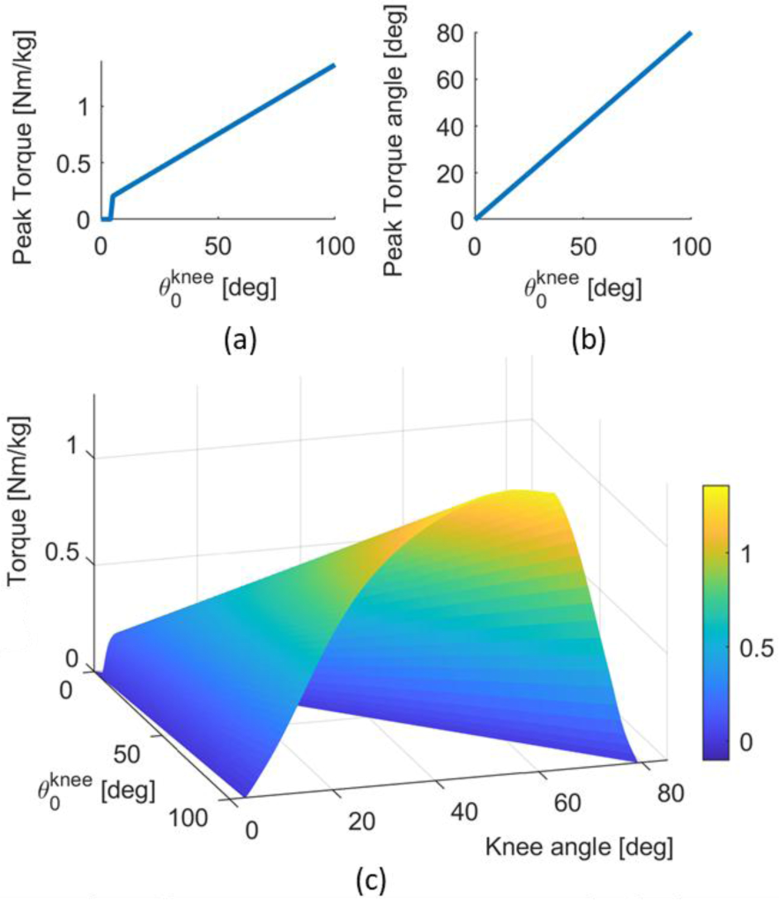
Stance Controller (a-b) Relationship between the knee position at the start of stance with respect to both the peak knee torque, and the knee position at peak torque. (c) Desired torque as a function of the knee positions for the knee joint during stance.
The ankle behavior during Stance is defined using an impedance controller with an adaptive virtual equilibrium angle . Due to the adaptive nature of the Swing controller, the angles of the powered ankle and knee joints at the transition between Swing and Stance (i.e., , ) are not fixed but change as a function of the user’s thigh orientation and acceleration as defined by (1–7). Thus, at the transition between Swing and Stance, the equilibrium angle of the ankle is set to the measured ankle angle . Then, the equilibrium angle of the ankle changes linearly with the knee position as defined by (8), where , are the angle of the ankle and knee joint, respectively, at the transition between Swing and Stance.
| (8) |
With the proposed Stance controller, the powered ankle joint moves from whatever its initial angle is when the prosthetic foot contacts the step to a neutral position (i.e., 0°) as the powered knee joint extends from its measured angle when the prosthetic foot contacts the step to zero (i.e., fully extended position). Thus, the powered ankle can contribute positive power to the Stance movement. At the same time, if the subject shuffles around without taking a step, the ankle stays in a neutral position while providing compliant support to help the user balance while standing. The knee flexion to ankle dorsiflexion ratio defined in (8) is inspired by biomechanical analysis of nonamputee subjects climbing stairs with different heights, gait patterns, and cadences as well as from the biomechanical analysis of individuals with an above-knee amputation using our previous, non-adaptive stair ascent controller [28].
The proposed controller uses a finite-state machine with two states (i.e., Stance and Swing) to transition between the two controllers (Fig.3. (a)). When the ground reaction force (GRF) is lower than a predefined threshold (, TABLE I) the stair controller is in Swing. Whenever the ground reaction force (GRF) is higher than a fixed threshold (, TABLE I), the prosthesis controller transitions from Swing to Stance.
Fig.3.
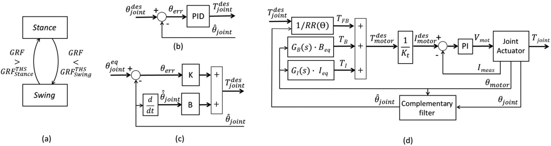
Block diagrams of the (a) finite-state machine, (b) mid-level position controller, (c) mid-level impedance controller, and (d) low-level torque controller.
TABLE I.
Adaptive Swing Control Parameters
| Parameter | Value | Fixed/tuned |
|---|---|---|
| Tuned | ||
| 0.02 s | Fixed | |
| 1.05 g | ||
| 1.05 g | ||
| 10 deg | ||
| 120 N | ||
| 40 N |
The desired torque or angle defined by the Stance and Swing controllers are enforced by a dedicated low-level controller using a hybrid feedforward/feedback approach. During Swing, closed-loop position controllers (Fig.3(b)) are used to impose the desired joint angles at the ankle and knee joints. For each powered joint, the closed-loop position controller takes as input the desired angle and compares it to the measured angle , which is estimated using a complementary filter. The angle error is fed to a PID controller that determines the desired torque command . In Stance, the ankle joint uses a virtual impedance controller [11], [18] (Fig.3(c)) with predefined stiffness and damping parameters (K, B) to define the desired torque command . Also, in Stance, the knee controller defines the desired torque command using the approach shown in Fig.3. The desired torque command is then sent to a low-level torque controller (Fig.3(d)).
The low-level torque controller comprises a feedforward command based on the position-dependent transmission ratio (RR(θ)). In addition, two compensators are used to reduce the apparent impedance (i.e., viscosity and inertia) of the transmission system improving the fidelity of the virtual impedance controller [20]. The first one (i.e., GB(s) · Beq) takes as input the motor position and generates an online estimate of the viscous torque due to the linear actuator. The second one takes as input the motor position and computes a scaled and low-pass filtered estimate of the transmission inertia (i.e., GI(s) · Ieq). The performance of the proposed low-level controller was validated in our previous study [29].
III. Powered Knee and Ankle Prosthesis
For this experiment, we used the Utah Lightweight Leg. This powered knee and ankle prosthesis can generate biologically appropriate torque and power during ambulation while fitting within the 1st percentile male leg profile [17]. The Utah Lightweight Leg weighs ~2.7 kg including battery and protective covers–approximately half of similar powered prostheses [20].
The ankle-foot module uses a compact, lightweight powered polycentric design, which is contained within a commercially-available foot shell [30][31]. The powered polycentric mechanism is connected to custom carbon-fiber feet of different sizes to accommodate different subjects. The knee module uses an actively variable transmission [16], [32] to optimize the effective transmission ratio and leg dynamics for different locomotion tasks. In addition, the knee module contains the battery, control electronics, and motor drivers for both the knee and ankle joints [17]. The knee and ankle modules connect with a standard 30-mm pylon allowing for height and intra-extra rotation adjustments. A custom instrumented pyramid adapter is located at the top of the ankle module to estimate the ground reaction force and torque [33].
The Utah Lightweight Leg is equipped with position sensors at the knee and ankle joints as well as at the motor shafts. Three 9-DOF IMUs (MPU9250, Invsense) sense the movements and the orientation of the foot, shank, and thigh segments in space. The 3-D printed protective covers host the Li-Ion battery (2500 mAh, 6S) and the onboard system-on-module (MyRio 1900, National Instruments). The system-on-module runs all control algorithms in real-time at 500Hz while interfacing with all the embedded sensors and the servo drivers for the knee and ankle modules. The system-on-module can be connected through Wi-Fi to a host computer or smartphone for data monitoring and controller tuning. The system-on-module is programmed in Labview™ (National Instruments). More details on the implementation and bench top testing of the proposed controller can be found in our previous work [16], [30]–[32].
IV. Human Experiments
A. Subject information
One subject with an above-knee amputation was recruited to participate in the study. Before the study took place, the subject provided written informed consent to participate, including written consent to use photos and videos of the experiment for dissemination purposes. The subject is 27 years old, weighs 65 kg, is a 1.7 m tall male, and has had an above-knee amputation for 6 years. The subject had prior experience with this powered prosthesis through participation in other studies. However, he did not have prior experience with the proposed controller. All study protocols were approved by the University of Utah Institutional Review Board.
B. Experiment Preparation
The experiment preparation took place before data collection. The subject donned the Utah Lightweight Leg [17], [30], which is a fully powered, modular, and self-contained knee and ankle prosthesis. A certified prosthetist adjusted the build height of the prosthesis using a standard pylon and ensured proper alignment of the knee and ankle joints. After the prosthesis fitting was completed, the subject donned an IMU-based motion capture system [34] (MTw Awinda, Xsens). Eight sensors were placed on the subject. Two sensors were placed on the top of each foot, two on each shank just below the knee joint, two on the outside of each thigh, one in the center of the lower back, and one sensor on the sternum. Then, the motion capture system was calibrated to the subject. The calibration protocol consisted of having the subject stand still for 5 seconds, take 3 strides forward, turn around, take another 3 strides, and return the original standing position [34]. After the system calibration was successfully completed, the subject practiced climbing stairs with the proposed controller for about 15 minutes on both the 4in and 7in staircase. During practice, the controller parameters were fine-tuned by the experimenter based on the subject’s preference. The whole experiment preparation lasted about 30 minutes. About 15 minutes for prosthesis fitting and motion system calibration, and about 15 minutes for controller tuning and practice.
The proposed controller relies on a series of bioinspired curves (Fig.1, Fig.2), modulated using several coefficients and parameters. Specifically, there are ten parameters in the controller. The initial values of these ten parameters were determined through simulations and pilot tests with nonamputee subjects using a bypass orthosis. During the experiment with a subject with an above-knee amputation, four parameters were tuned using the protocol described below while the other six parameters were kept constant. To tune the controller, we first asked the subject to place the prosthesis on the step in front of them without climbing it. With the prosthesis on the step, we fine-tuned and to achieve a natural, comfortable posture, while making sure that the prosthesis shank was slightly tilted forward, and the prosthetic foot was flat on the step (Fig.4). Then, we asked the subject to climb the staircase step-by-step, leading with the sound side. As the subject climbed the steps, we fine-tuned and making sure that the powered prosthesis cleared the steps. Finally, we asked the subject to climb stairs step-over-step and verified the controller. The whole tuning procedure was performed on the 7-in staircase only. TABLE I shows the final values of all the control parameters, specifying fixed and tuned parameters. Specifically for the tuned parameters, all values have a sign constraint greater than zero.
Fig.4.
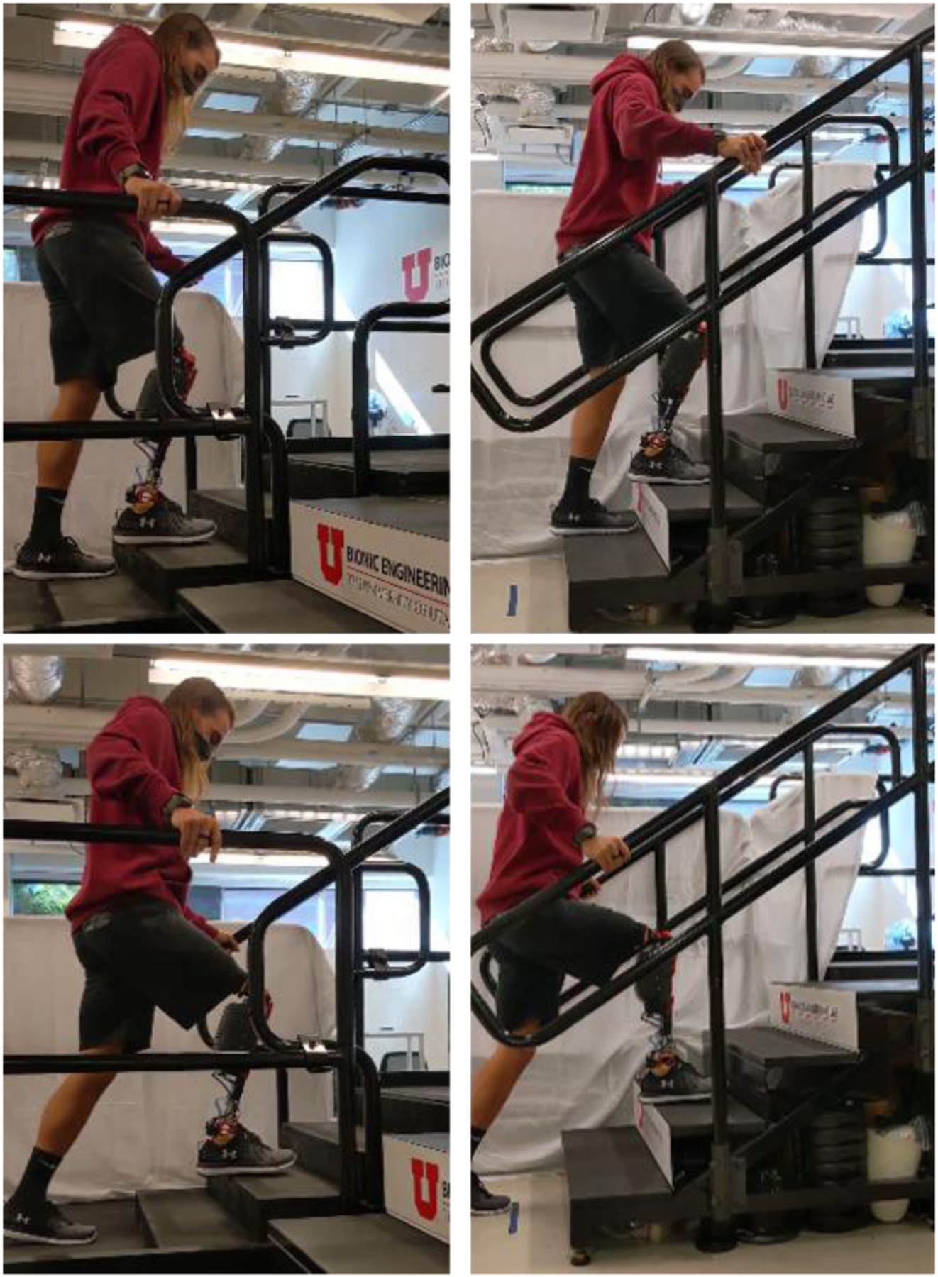
The subject climbs stairs with the Utah Lightweight Leg. 4-in stairs on the left, 7-in stairs on the right. Step-by-step and step-over-step gait pattern shown on top, two-step gait pattern shown on bottom.
C. Experimental Protocol
After the experiment preparation was completed, the subject performed the experimental protocol for data collection. The subject was asked to ascend two staircases of four steps, each with three different gait patterns. The first staircase is the maximum ADA compliant step height of 7 inches (18 cm), the second staircase is the minimum ADA compliant step height of 4 inches (10 cm) [35]. First, the subject used the step-over-step gait pattern, which is the most common way to climb stairs for non-amputee individuals. When climbing stairs step-over-step, each foot is placed one step above the other foot. Then, the subject used a step-by-step gait pattern. When climbing stairs step-by-step, the leading foot is placed one step above, and the following foot is brought to match on the step of the leading foot. Finally, the subject used a two-steps gait pattern, which is less common and mostly used when in a hurry. When climbing stairs with the two-steps gait pattern, the leading leg is taking two-steps at a time and the following leg is brought to match that step. The subject performed 5 ascents for each gait pattern and staircase. The subject was asked to climb the staircase at the preferred cadence. Thus, the protocol tested all possible combinations of gait patterns and stair heights, while leaving the gait cadence up to the user’s preference.
Data acquired from the motion capture systems and the sensors embedded in the powered prosthesis were processed offline. The motion capture system provides the kinematics of the ankle, knee, and hip joint, the orientation of the leg segments, and the cartesian-space position of the toe, ankle, knee, and hip joints for both the prosthesis side and the sound side. The powered prosthesis provides the kinetics and kinematics of the prosthetic ankle and knee joints. Data recorded from the motion capture system and the powered prosthesis were synchronized online through Wi-Fi. The synchronized raw data was filtered offline using a zero-lag low-pass Butterworth filter with a cutoff frequency of 8 Hz. Joint angular velocities, accelerations, and power were calculated post-filtering. Segmentation indexes for stance and swing phase during stair ascent were determined using the gait state parameters defined online by the powered prosthesis controller. Full strides started and ended at toe-off on the prosthesis side. After segmentation, each stride was resampled to 1000 samples, and the time was normalized as percent of stride.
Energy injection was calculated as the integral of the joint torque-angle curve, which is theoretically equivalent to integrating mechanical power over time but does not require offline calculation of the joint velocity by numerical differentiation, which is typically noisy and involves filtering. Moreover, energy injection was calculated for stance phase only to isolate the ability of the proposed Stance controller to adapt the energy injection to both the step height (i.e., 4-in. vs. 7-in.) and the gait pattern (e.g., Two-Steps vs. Step-over-Step).
V. Results
The prosthesis swing trajectory varied between different stair heights and gait patterns (Fig.5). As shown in TABLE II, the maximum knee angle during swing was 88.5 ± 2.9°, 88.3 ± 2.6°, and 96.0 ± 1.9° for step-by-step, step-over-step, and two-steps gait patterns for the 7-in stairs, respectively (Fig.6). The maximum knee angle during swing was 74.9 ± 2.8°, 73.6 ± 1.8°, and 95.9 ± 1.5° for step-by-step, step-over-step, and two-steps gait patterns for the 4-in stairs, respectively (Fig.6). Thus, there were substantial differences in the maximum knee flexion angle between two-steps gait pattern and the step-by-step and step-over-step gait patterns but almost no difference between the step-by-step and step-over-step gait patterns. As expected, we found a noticeable difference between stair heights, with an 18% and 20% increase in knee flexion between the 7-in and 4-in stairs for the step-by-step and step-over-step gait patterns, respectively. Thus, the proposed controller provided sufficient foot clearance and proper foot placement for all observed gait patterns and stair heights.
Fig.5.

Analysis of the powered prosthesis during swing for different stair heights (7-in and 4-in, left to right, respectively) and gait patterns (step-by-step, step-over-step, two-steps, top to bottom, respectively). (a) Swing trajectory of the powered prosthesis in the cartesian space. The light lines correspond with the start of swing and the dark lines correspond with the end of swing. The black lines indicate the position of the toe throughout the swing movement. (b) Duration of swing mean and standard deviation for all stair heights and gait patterns. (c) Peak of the vertical toe position mean and standard deviation during swing for all stair heights and gait patterns.
TABLE II.
Comparison between different stair heights and gait patterns
| Variable | Step-By-Step | Step-Over-Step | Two-Steps | |
|---|---|---|---|---|
| Max Knee Flexion in Swing | 4-in | 74.9±2.8° | 73.6±1.8° | 95.9±1.5° |
| 7-in | 88.5±2.9° | 88.3±2.6° | 96.0±1.9° | |
| Thigh Angle Start of Stance | 4-in | −15.5±2.0° | −30.7±6.2° | −43.8±2.1° |
| 7-in | −40.6±3.1° | −40.6±3.5° | −57.9±3.1° | |
| Knee Angle Start of Stance | 4-in | 50.0±6.5° | 49.9±3.4° | 68.8±3.6° |
| 7-in | 75.3±1.0° | 74.5±1.9° | 84.4±5.3° | |
| Peak Knee Torque Stance | 4-in | 0.40±0.15 Nm/kg | 0.50±0.10 Nm/kg | 1.20±0.08 Nm/kg |
| 7-in | 1.06±0.06 Nm/kg | 1.03±0.04 Nm/kg | 1.44±0.15 Nm/kg | |
| Peak Knee Power Stance | 4-in | 1.52±0.63 W/kg | 1.90±0.43 W/kg | 3.60±0.68 W/kg |
| 7-in | 3.37±0.25 W/kg | 3.39±0.27 W/kg | 4.71±0.20 W/kg | |
| Stance Knee Energy Injection | 4-in | 0.17±0.08 J/kg | 0.20±0.04 J/kg | 0.64±0.08 J/kg |
| 7-in | 0.60±0.03 J/kg | 0.59±0.03 J/kg | 0.95±0.14 J/kg | |
| Peak Thigh Angle Stride | 4-in | −40.9±1.8° | −41.0±3.3° | −55.5±2.3° |
| 7-in | −55.7±2.0° | −56.4±0.8° | −61.6±3.9° | |
| Swing Duration | 4-in | 1.06±0.08 s | 0.85±0.09 s | 1.52±0.09 s |
| 7-in | 1.20±0.05 s | 1.18±0.13 s | 1.67±0.11 s | |
| Peak Toe Position Swing | 4-in | 0.17±0.02 s | 0.22±0.02 s | 0.32±0.01 s |
| 7-in | 0.29±0.01 s | 0.28±0.001 s | 0.48±0.01 s |
Fig.6.

Kinematic analysis of the thigh segment, knee joint, and ankle joint from top to bottom, respectively, for the step-by-step, step-over-step, and two-steps gait patterns from left to right, respectively. The prosthesis side mean and standard deviation is shown for all stair heights and gait patterns in blue for the 7-in stairs and orange for the 4-in stairs.
The swing duration was calculated from the moment the prosthetic foot left the ground to the moment the prosthetic foot touched the ground, as determined by the finite-state machine. Because the powered prosthesis continuously follows the residual-limb movements, the swing duration reflects the user’s self-selected cadence. The swing duration ranged from 0.76 s for the 4-in stairs with step-over-step gait pattern to 1.80 s for the 7-in stairs with the two-steps gait pattern (TABLE II). The step-over-step gait pattern on the 7-in stairs had the highest deviation in swing duration, with a minimum of 1.1 seconds and a maximum of 1.4 seconds (Fig.5). Thus, the proposed controller enabled the subject to change his cadence when climbing stairs with different heights or using different gait patterns.
The prosthesis angle at the start of stance varied for different stair heights and gait patterns. The knee angle at the start of stance (i.e., 0% Stance, Fig.7) was 75.3±1.0°, 74.5±1.9°, and 84.4±5.3° for step-by-step, step-over-step, and two-steps gait patterns for the 7-in stairs, respectively (TABLE II). The knee angle at the start of stance was 51%, 49%, and 23% larger on the 7-in stairs compared to the 4-in stairs for the step-by-step, step-over-step, and two-steps gait pattern, respectively (TABLE II). Also, the knee angle at the start of stance was 50.0±6.5°, 49.9±3.4°, and 68.8±3.6° for step-by-step, step-over-step, and two-steps gait patterns for the 4-in stairs, respectively (TABLE II). Thus, the knee angle was 13% and 38% larger for the two-steps gait pattern compared to the single-step gait patterns for the 7-in and 4-in stair heights, respectively. Thus, the proposed controller changed the prosthesis knee angle at the start of stance adapting to the different gait patterns and stair heights.
Fig.7.
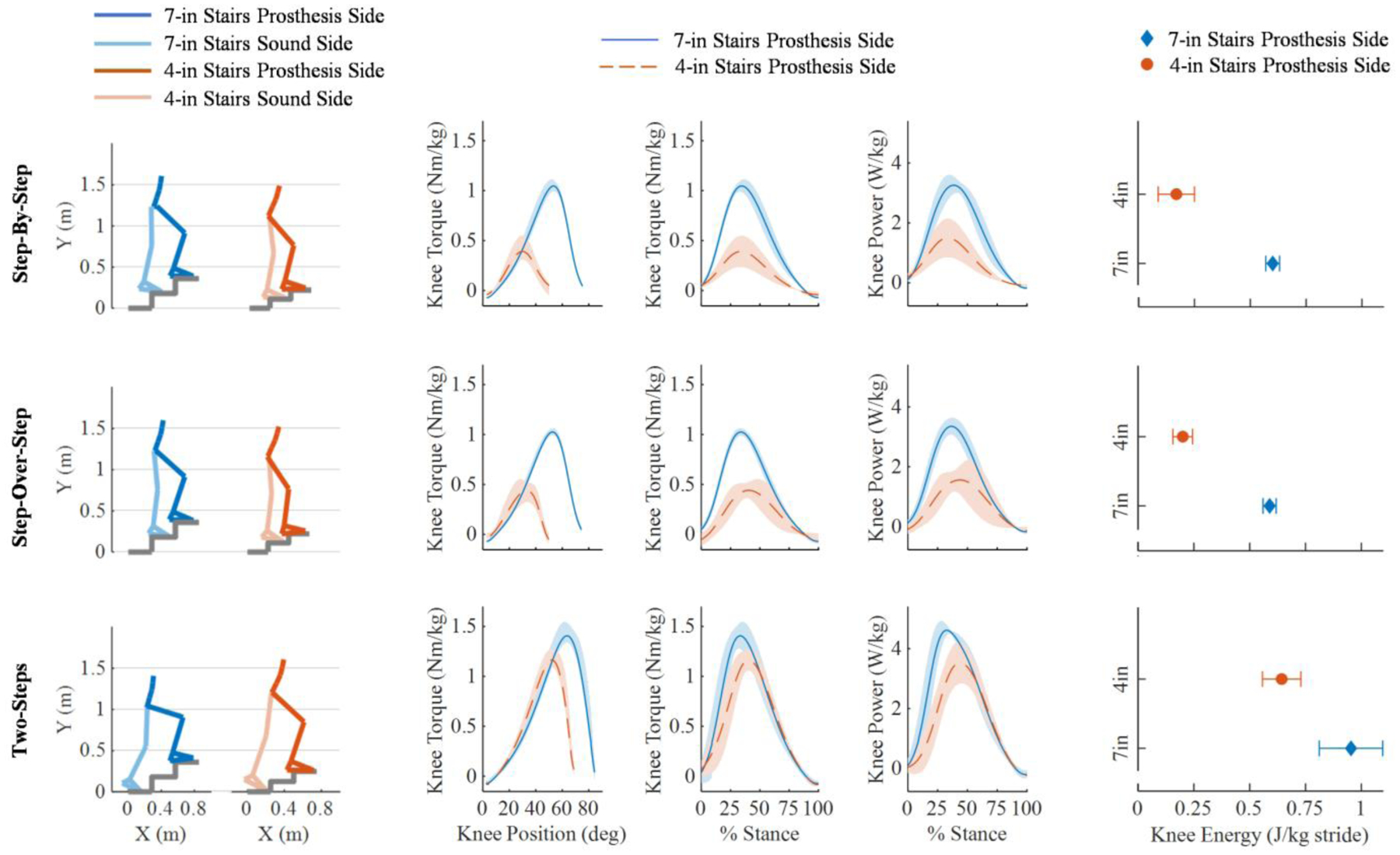
Kinetic analysis of the stance phase. The step-by-step, step-over-step, and two-steps gait patterns are displayed from top to bottom, respectively. The first two columns show the sound side and the prosthesis side orientation in the cartesian space at the start of stance (e.g. 0% stance) for the 7-in stairs on the left and 4-in stairs on the right. The powered prosthesis knee torque against knee position plots druing stance phase, knee torque against % stance and knee power against % stance are shown in columns 3 to 5 for all conditions. The powered prosthesis side mean and standard deviation is in blue for the 7-in stairs and orange for the 4-in stairs. The plots in the right column show the mean and standard deviations of the energy injection for all stair heights and gait patterns.
The peak of the prosthesis knee torque changed with different stair heights and gait patterns (Fig.7). The peak knee torque was 1.06 ± 0.06 Nm/kg, 1.03 ± 0.04 Nm/kg, and 1.44 ± 0.15 Nm/kg for step-by-step, step-over-step, and two-steps gait patterns for the 7-in stairs, respectively (TABLE I). Thus, the peak knee torque increased by 38% and 166% for the two-steps gait pattern compared to the single-step gait patterns for the 7-in and 4-in stairs, respectively. The peak knee torque was 0.40 ± 0.15 Nm/kg, 0.50 ± 0.10 Nm/kg, and 1.20 ± 0.08 Nm/kg for step-by-step, step-over-step, and two-steps gait patterns for the 4-in stairs, respectively (Fig.7). Thus, the peak knee torque measured for the 7-in stairs was 164%, 106%, and 20% larger compared to the 4-in stairs for the step-by-step, step-over-step, and two-steps gait pattern, respectively.
The timing of the prosthesis knee torque peak varied for different stair heights and gait patterns (Fig.7). The peak knee torque was provided at a knee angle of 29.9°, 33.6°, and 52.7° for the step-by-step, step-over-step, and two-steps gait patterns, respectively, for the 4-in stairs and 53.6°, 52.6°, and 64.2° for the step-by-step, step-over-step, and two-steps gait patterns, respectively, for the 7-in stairs. Thus, the knee angle at peak torque was 30% smaller than the knee angle at the start of stance. The proposed controller changed the torque based on the gait pattern and stair height.
We assessed joint power and energy injection for different stair heights and gait patterns. The peak knee power was 3.37 ± 0.25 W/kg, 3.39 ± 0.27 W/kg, and 4.71 ± 0.20 W/kg for the step-by-step, step-over-step, and two-steps gait patterns for the 7-in stairs, respectively (Fig.7). The peak knee power was 1.52 ± 0.63 W/kg, 1.90 ± 0.43 W/kg, and 3.60 ± 0.68 W/kg for the step-by-step, step-over-step, and two-steps gait patterns for the 4-in stairs, respectively (Fig.7). The energy injected in stance was 0.60 ± 0.03 J/kg, 0.59 ± 0.03 J/kg, and 0.95 ± 0.14 J/kg for the step-by-step, step-over-step, and two-steps gait patterns for the 7-in stairs, respectively (Fig.7). The energy during stance was 0.17 ± 0.08 J/kg, 0.20 ± 0.04 J/kg, and 0.64 ± 0.08 J/kg for the step-by-step, step-over-step, and two-steps gait patterns for the 4-in stairs, respectively (Fig.7). Thus, the two-steps gait pattern injected 60% and 246% more energy compared to the single-step gait patterns (Fig.7) for the 7-in and 4-in stairs, respectively. The 7-in stairs injected 253%, 195%, and 48% more energy compared to the 4-in stairs for the step-by-step, step-over-step, and two-steps gait patterns, respectively. The proposed controller injected a different amount of energy into the gait cycle depending on the gait pattern and stair height.
A kinematic analysis was performed between the sound side and the prosthesis side for the thigh orientation, knee angle, and ankle angle. The peak knee angle on the sound side was 88.5 ± 2.9° and 70.1 ± 3.7° for the 7-in and 4-in stairs, respectively (TABLE III). At toe-off, or 0% stride, the sound side for the 4-in stairs experiences some initial flexion of −8.0 ± 2.2° for the thigh and 17.1 ± 2.5° for the knee compared to the sound side for the 7-in stairs and both stair heights of the prosthesis side where the knee and thigh positions at toe-off are closer to a neutral position (Fig.8). Additionally, the ankle on the sound side experiences −32.1 ± 10.8° and −27.6 ± 11.0° of plantarflexion at toe-off for the 7-in and 4-in stair heights, respectively, where the prosthesis side starts with a more neutral ankle position for both the 7-in and 4-in stairs, respectively. The peak plantarflexion angle on the prosthesis side was −25.2 ± 0.07° and −25.2 ± 0.07° for the 7-in and 4-in stairs, respectively. The peak plantarflexion angle on the sound side was −51.4 ± 2.3° and −39.7 ± 4.7° for the 7-in and 4-in stairs, respectively. Thus, the sound side experiences 104% and 58% more plantarflexion compared to the prosthesis side for the 7-in and 4-in stairs, respectively (TABLE III). The peak dorsiflexion angle on the prosthesis side was 20.0 ± 1.0° and 20.2 ± 1.7° for the 7-in and 4-in stairs, respectively. The peak dorsiflexion angle on the sound side was 14.8 ± 1.5° and 7.8 ± 2.2° for the 7-in and 4-in stairs, respectively. The proposed controller enabled the subject to climb stairs with different heights using three different gait patterns step-over-step, step-by-step, and two steps at a time. For the step-over-step gait pattern, the right and left leg are expected to show the same kinematics. However, there are some noticeable differences between the kinematics of the sound side and the prosthesis side, especially between the ankle joints. For step-by-step and two-steps patterns, the right and left leg are not expected to show the same kinematics. Therefore, the comparison between the sound side and the prosthesis side is not reported.
TABLE III.
Comparison between sound side and prosthesis side
| Variable | Sound Side | Prosthesis Side | |
|---|---|---|---|
| Max Knee Flexion | 4-in | 70.1±3.7° | 73.6±1.8° |
| 7-in | 88.5±2.9° | 88.3±2.6° | |
| Max Thigh Position | 4-in | −38.5±2.4° | −41.0±3.3° |
| 7-in | −53.9±1.6° | −56.4±0.8° | |
| Max Ankle Plantarflexion | 4-in | −39.7±4.7° | −25.2±0.07° |
| 7-in | −51.4±2.3° | −25.2±0.07° | |
| Max Ankle Dorsiflexion | 4-in | 7.8±2.2° | 20.2±1.7° |
| 7-in | 14.8±1.5° | 20.0±1.0° |
Fig.8.
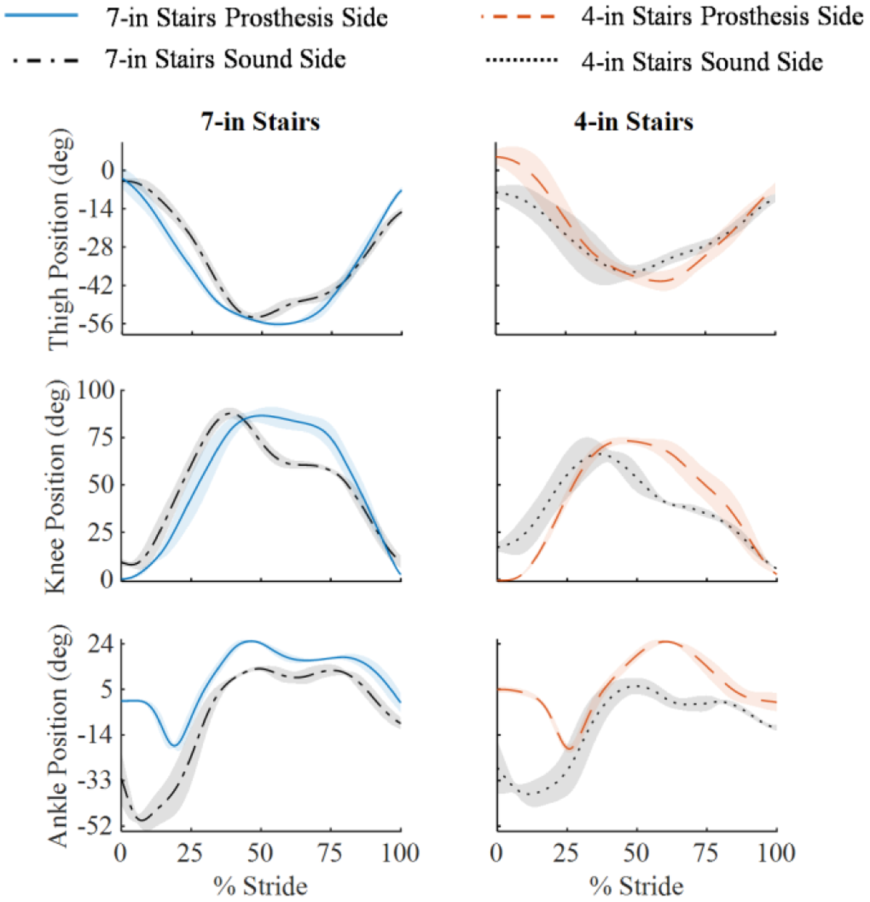
Kinematic analysis of the thigh segment, knee joint, and ankle joint from top to bottom, respectively, for the step-over-step gait pattern. The left column is the 7-in stairs and the right column is the 4-in stairs. The prosthesis side and sound side mean and standard deviation is shown for all stair heights.
VI. Discussion
Ascending stairs in the real world requires controllers that synchronize the movements of the powered prosthetic joints with the movements of the user’s residual limb. If the controller moves too fast or too slow with respect to the user’s residual limb, then the prosthesis will hit the stairs, causing the user to trip and fall. Available stair controllers for powered prostheses cannot synchronize with the user [14]–[22]. Therefore, users must learn how to time their residual limb movements with the prosthesis to ensure that the step is cleared. Because the swing time is fixed, changing cadence is not possible with available stair ascent controllers. This study shows that the proposed adaptive Swing controller (Fig.1) enables climbing stairs at a variable cadence (from 0.76 s/stride to 1.8 s/stride, TABLE II), which is critical to ambulate on staircases with different heights (4-in., 7-in.) or using different gait patterns (step-by-step, step-over-step, two-steps). Thus, the experimental results suggest that the proposed Swing controller enables climbing stairs with different heights and gait patterns by intrinsically synchronizing with the user’s thigh movements.
Adaptation to different staircases or gait patterns requires the position of the prosthetic foot at the end of swing to match the stair height. If the prosthetic knee is too flexed, then the prosthetic foot hovers above the step. If the prosthetic knee is not flexed enough, the prosthetic foot does not clear the last step. Moreover, the angle of the prosthetic joints at the start of stance is critical. The knee joint must be flexed to an extent that ensures the prosthesis shank orientation is past the vertical line defined by gravity so that the user’s center of mass is above the prosthesis [13]. The ankle must be dorsiflexed to ensure the prosthetic foot stays flat on the step. Available stair controllers are tuned for a specific staircase and gait pattern [14]–[22] so that proper foot placement is achieved. Outside of the specific tuning conditions, these controllers cannot provide proper toe clearance and foot placement. This study shows that the proposed adaptive Swing controller can achieve a suitable prosthesis orientation for all tested stair heights and gait patterns by changing the knee flexion continuously with the thigh angle (TABLE II, Fig.5, Fig.6). Similarly, our experimental results show that the ankle angle is continuously adapted based on gravity (Fig.5, Fig.6), enabling the prosthetic foot to remain perpendicular to the step for all tested stair heights and gait patterns (TABLE II, Fig.5, Fig.6). Thus, the experimental results suggest that the proposed adaptive Swing controller provides proper foot placement for different stair heights and gait patterns.
Biomechanical analysis of nonamputee gait and pilot tests with our powered prosthesis indicated that changing the prosthesis knee and ankle angles as a function of only the user’s thigh angle does not provide sufficient toe clearance during swing. For this reason., in our controller, the prosthesis joint angles depend on both the thigh angle, velocity and vertical acceleration as defined by (1–7). In general, the velocity dependency (2) seems to help clearing the intermediate step, whereas the vertical acceleration term (3) seems to have a major impact in clearing the first step, when the residual limb is not rotating (Fig.5). Thus, the experimental results suggest that the residual limb orientation, velocity, and vertical acceleration are suitable combination of inputs to continuously adapt the prosthesis trajectory during stair ascent.
Climbing stairs with different stair heights or gait patterns requires different torque generation and mechanical energy injection [12]. However, available stair ascent controllers use either a fixed, pre-programmed stance torque profile or joint impedance. Therefore, they cannot change torque generation or energy injection. To address this limitation, the proposed Stance controller automatically increases the maximum knee torque proportionally to the knee flexion angle at the beginning of stance (Fig.2). Our experimental results show that because the knee flexion angle at the beginning of stance is proportional to the stair height (Fig.2, Fig.7), the energy injected by the prosthesis is also proportional to the stair height (Fig.7). Thus, the experimental results suggest that the proposed Stance controller provides sufficient modulation of torque and energy injection to enable climbing stairs with different heights and gait patterns.
Inspired by biological knee behavior, the proposed controller sets the knee angle at which the peak knee torque is provided proportional to the knee range of motion (Fig.2). Our experimental results show that the torque-angle relationship is scaled linearly on the knee range of movement (Fig.7), and the knee angle at peak torque changes depending on the stair height and gait pattern (Fig.7). Because the energy injection is independent with respect to time, the user was able to climb stairs at their desired cadence while still receiving the assistance needed. Thus, the experimental results suggest that the proposed Stance controller synchronizes energy injection to the user’s movements when climbing stairs with different heights and gait patterns.
In the proposed Stance controller, the ankle movements are synchronized to the knee movements, using a dedicated adaptive function (8). The experimental results show that different ankle angles are achieved at the beginning of stance for different stair heights and gait patterns (Fig.7). However, for all tested conditions the ankle angle gradually returns to neutral as the knee extends (Fig.7). Thus, the experimental results suggest that the proposed Stance controller indirectly synchronizes the ankle movements to the residual limb movements when climbing stairs with different heights and gait patterns.
Like other stair controllers for powered prostheses [14]–[22], the proposed controller uses a finite-state machine (Fig.3). However, we only use two states (Stance and Swing), whereas other stair controllers use at least four states. In general, reducing the number of states in the finite-state machine reduces the probability of a wrong transition being triggered, improving robustness. Moreover, reducing the number of states reduces the number of control parameters that need to be tuned, reducing tuning time [18]. The results of our experiments show that two states are sufficient for the proposed controller to achieve the desired adaptability to different stair heights, gait patterns, and cadence.
A. Limitations
Non-amputee stair biomechanics show the ankle joint provides considerable energy during late stance. The proposed controller is not capable of imitating this important physiological function. Powered ankle push-off has been obtained in a previous study using a finite-state machine with a dedicated late-stance state signaled by an intermediate threshold on the ground reaction force [19], [21]. In our pilot studies, this late-stance state caused the ankle to push-off when the users shuffled instead of climbing stairs. This observation suggests that integrating ankle push-off in our stair ascent controller will require an understanding of the sound side position to ensure that the user wants to climb a step rather than shuffling. Future work should focus to address this limitation so that the proposed controller can more closely imitate the physiological ankle push-off.
The analysis of nonamputee stair biomechanics suggests that at the transition from swing to stance the body weight is loaded on the middle to the front portion of the foot while the ankle joint is slightly plantarflexed [13]. In contrast, our controller aims for a flat foot placement at this transition to minimize the amount of joint movement occurring underneath the user. Further experiments are necessary to understand the impact of this discrepancy between the biological ankle behavior and that of our controller on the user.
Because the prosthesis movements are intrinsically synchronized to the user’s residual limb movements, the proposed Swing controller does not need to explicitly classify the intent of the user to ascend stairs. In other terms, the user can safely stand and shuffle around without triggering a predefined swing movement like in previous controllers. However, this aspect has not been properly investigated and further work is necessary to quantify the impact of the proposed controller on the user’s intent classification problem. It is also unclear whether the proposed adaptive stair controller can be integrated with adaptive walking controllers [36] in a way that does not require explicit classification of the user’s intent to climb stairs or walk.
The subject did not stub his toe in any of the recorded steps. In general, the proposed controller transitions to Stance whenever the physical interaction with the environment generates a substantial vertical ground reaction force (Fig.3(a)). However, it is not clear whether stubbing the toe would cause such a vertical force. Thus, it is not clear how the proposed controller would react in this situation.
The proposed controller requires subject-specific tuning. Manual (e.g., [18]) and automatic tuning (e.g., [37]) are common for powered research prostheses and microprocessor-controlled prostheses available on the market [38]. In this experiment, which included one subject, we tuned four control parameters, leaving the other six parameters fixed (Table I). In our study, tuning the proposed controller took about 15 minutes. This tuning time is equivalent to that necessary for non-adaptive controllers like the ones used in our previous studies [16], [28] and by other researchers [18], [22], [39]. Moreover, this tuning time is equivalent to the tuning time needed by clinicians to set up microprocessor-controlled prostheses. This result suggests that the tuning process should not limit the clinical viability of the proposed controller. However, it is possible that more parameters will need to be tuned to adapt the proposed controller to different subjects, increasing the tuning time. Further work is necessary to quantify tuning time in a broader amputee population.
An important limitation of this study is that it does not address generalization to the broad amputee population. Although the experiments with one subject with an above-knee amputation provide a first demonstration of stair climbing with different stair heights, gait patterns, and cadences, we do not know whether the proposed controller will provide similar results in other individuals with above-knee amputation. Future clinical evaluations should assess the generalizability of the proposed controller in a broader amputee population, perhaps using an instrumented staircase.
VII. Conclusion
The ability to enable climbing stairs step-over-step is one of the biggest advantages of powered prostheses over conventional passive devices. Climbing stairs in the real world requires the powered prosthesis controller to adapt to variability in stair geometry, gait pattern, and gait cadence. The proposed Swing controller enables a powered prosthesis to adapt the swing trajectory continuously, while coordinating with the movements of the user, without explicit classification of the environment. The proposed Stance controller enables a powered prosthesis to adapt the timing and amount of energy injected in stance based on the changing needs of the user. Our experiment with one individual with an above-knee amputation suggests that the proposed stair controller enables climbing stairs with different heights at the preferred cadence and using different gait patterns. A controller with this capability may improve real-world ambulation and is not currently available to prosthesis users. Future work should provide statistical evidence in a larger clinical population comparing the proposed adaptive approach to passive prostheses and powered prostheses using other control approaches.
Acknowledgments
The authors would like to thank Kyle Rasmussen, CP for his help fitting the Utah Lightweight Leg to the subject. The authors would also like to thank Joel Mendez and Andy Gunnell for their help setting up the motion capture system and processing the experimental data.
This work was supported in part by the NSF grant number 1925343, the NIH under grant number R01HD098154, and the Department of Defense under grant number W81XWH2110037.
Biographies

Sarah Hood received the B.Sc. degree in mechanical engineering from Florida State University, Tallahassee, FL, USA in 2017 and the M.Sc. degree in mechanical engineering from the University of Utah, Salt Lake City, UT, in 2020.
She is currently pursuing the Ph.D. degree in mechanical engineering with the University of Utah. Her research interests include wearable robots and biomechanics.

Lukas Gabert received the B.Sc. degree in mechanical engineering from the New Mexico Institute of Mining and Technology, Socorro, NM, USA in 2016; the M.Sc. and Ph.D. degrees in mechanical engineering from the University of Utah, Salt Lake City, UT, in 2019 and 2022, respectively.
He is currently an Engineering Manager for the Bionic Engineering Lab at the University of Utah. He has extensive experience in the design, development, and testing of wearable robots. His interests lie at the intersection of mechanical design, embedded systems, and controls.

Tommaso Lenzi (M’11-M’13) received the M.Sc. degree in biomedical engineering from the University of Pisa, Pisa, Italy, in 2008, and the Ph.D. degree in BioRobotics from Scuola Superiore Sant’Anna, Pisa, in 2012. Previously, he was a Postdoctoral Fellow at Northwestern University, Chicago, IL, from 2013–2014 and a Research Scientist at the Rehabilitation Institute of Chicago, Chicago, IL, from 2015–2016.
He is currently an Assistant Professor with the Department of Mechanical Engineering, University of Utah, Salt Lake City, UT. He is also core faculty with the Utah Robotics Center. His main research interests include robotics, mechatronics, and rehabilitation medicine with a major emphasis on the design and control of wearable robots for human assistance and rehabilitation.sss
References
- [1].Segal AD et al. , “Kinematic and kinetic comparisons of transfemoral amputee gait using C-Leg and Mauch SNS prosthetic knees,” J. Rehabil. Res. Dev, vol. 43, no. 7, p. 857, 2006. [DOI] [PubMed] [Google Scholar]
- [2].Winter D, “Energy generation and absorption at the ankle and knee during fast, natural, and slow cadences,” Clin. Orthop. Relat. Res, vol. 175, pp. 147–154, 1983. [PubMed] [Google Scholar]
- [3].Bae TS, Choi K, Hong D, and Mun M, “Dynamic analysis of above-knee amputee gait,” Clin. Biomech, vol. 22, no. 5, pp. 557–566, 2007. [DOI] [PubMed] [Google Scholar]
- [4].Lura DJ, Wernke MW, Carey SL, Kahle JT, Miro RM, and Highsmith MJ, “Crossover study of amputee stair ascent and descent biomechanics using Genium and C-Leg prostheses with comparison to non-amputee control,” Gait Posture, vol. 58, no. July, pp. 103–107, 2017. [DOI] [PMC free article] [PubMed] [Google Scholar]
- [5].Hobara H et al. , “Lower extremity joint kinematics of stair ascent in transfemoral amputees,” Prosthet. Orthot. Int, vol. 35, no. 4, pp. 467–472, 2011. [DOI] [PubMed] [Google Scholar]
- [6].Hafner BJ, Willingham LL, Buell NC, Allyn KJ, and Smith DG, “Evaluation of Function, Performance, and Preference as Transfemoral Amputees Transition From Mechanical to Microprocessor Control of the Prosthetic Knee,” Arch. Phys. Med. Rehabil, vol. 88, no. 2, pp. 207–217, Feb. 2007. [DOI] [PubMed] [Google Scholar]
- [7].Gauthier-Gagnon C, Grise M-C, and Potvin D, “Enabling factors related to prosthetic use by people with transtibial and transfemoral amputation,” Arch. Phys. Med. Rehabil, vol. 80, no. 6, pp. 706–713, 1999. [DOI] [PubMed] [Google Scholar]
- [8].Hobara H, Kobayashi Y, Nakamura T, Yamasaki N, and Ogata T, “Foot clearance strategy for step-over-step Stair climbing in transfemoral amputees,” Prosthet. Orthot. Int, vol. 38, no. 4, pp. 332–335, 2014. [DOI] [PubMed] [Google Scholar]
- [9].Jaegers SM, Arendzen JH, and de Jongh HJ, “Changes in hip muscles after above-knee amputation,” Clin Orthop Relat Res, no. 319, pp. 276–284, 1995. [PubMed] [Google Scholar]
- [10].Ülger Ö, Topuz S, Bayramlar K, Erbahçeci F, and Şener G, “Risk factors, frequency, and causes of falling in geriatric persons who has had a limb removed by amputation,” Top. Geriatr. Rehabil, vol. 26, no. 2, pp. 156–163, 2010. [Google Scholar]
- [11].Goldfarb M, Lawson BE, and Shultz AH, “Realizing the promise of robotic leg prostheses.,” Sci. Transl. Med, vol. 5, no. 210, pp. 210–215, 2013. [DOI] [PubMed] [Google Scholar]
- [12].Riener R, Rabuffetti M, and Frigo C, “Stair ascent and descent at different inclinations.,” Gait Posture, vol. 15, no. 1, pp. 32–44, Feb. 2002. [DOI] [PubMed] [Google Scholar]
- [13].McFadyen BJ and Winter DA, “An integrated biomechanical analysis of normal stair ascent and descent,” J. Biomech, vol. 21, no. 9, pp. 733–744, 1988. [DOI] [PubMed] [Google Scholar]
- [14].Hoover CD, Fulk GD, and Fite KB, “Stair ascent with a powered transfemoral prosthesis under direct myoelectric control,” IEEE/ASME Trans. Mechatronics, vol. 18, no. 3, pp. 1191–1200, 2013. [Google Scholar]
- [15].Lawson BE, Varol HA, Huff A, Erdemir E, and Goldfarb M, “Control of stair ascent and descent with a powered transfemoral prosthesis,” IEEE Trans. Neural Syst. Rehabil. Eng, vol. 21, no. 3, pp. 466–473, Oct. 2013. [DOI] [PubMed] [Google Scholar]
- [16].Lenzi T, Cempini M, Hargrove L, and Kuiken T, “Design, development, and testing of a lightweight hybrid robotic knee prosthesis,” Int. J. Rob. Res, vol. 37, no. 8, pp. 953–976, Jul. 2018. [Google Scholar]
- [17].Tran M, Gabert L, Cempini M, and Lenzi T, “A Lightweight, Efficient Fully Powered Knee Prosthesis With Actively Variable Transmission,” IEEE Robot. Autom. Lett, vol. 4, no. 2, pp. 1186–1193, Apr. 2019. [Google Scholar]
- [18].Simon AM et al. , “Configuring a Powered Knee and Ankle Prosthesis for Transfemoral Amputees within Five Specific Ambulation Modes.,” PLoS One, vol. 9, no. 6, p. e99387, Jan. 2014. [DOI] [PMC free article] [PubMed] [Google Scholar]
- [19].Ledoux ED and Goldfarb M, “Control and Evaluation of a Powered Transfemoral Prosthesis for Stair Ascent,” IEEE Trans. Neural Syst. Rehabil. Eng, vol. 25, no. 7, pp. 917–924, Jul. 2017. [DOI] [PubMed] [Google Scholar]
- [20].Lawson BE, Mitchell J, Truex D, Shultz A, Ledoux E, and Goldfarb M, “A Robotic Leg Prosthesis: Design, Control, and Implementation,” IEEE Robot. Autom. Mag, vol. 21, no. 4, pp. 70–81, Dec. 2014. [Google Scholar]
- [21].Culver S, Bartlett H, Shultz A, and Goldfarb M, “A stair ascent and descent controller for a powered ankle prosthesis,” IEEE Trans. Neural Syst. Rehabil. Eng, vol. 26, no. 5, pp. 993–1002, 2018. [DOI] [PubMed] [Google Scholar]
- [22].Azocar AF, Mooney LM, Duval JF, Simon AM, Hargrove LJ, and Rouse EJ, “Design and clinical implementation of an open-source bionic leg,” Nat. Biomed. Eng, vol. 4, no. 10, pp. 941–953, Oct. 2020. [DOI] [PMC free article] [PubMed] [Google Scholar]
- [23].Simon AM, Fey NP, Finucane SB, Lipschutz RD, and Hargrove LJ, “Strategies to reduce the configuration time for a powered knee and ankle prosthesis across multiple ambulation modes.,” IEEE Int. Conf. Rehabil. Robot, vol. 2013, pp. 1–6, Jun. 2013. [DOI] [PubMed] [Google Scholar]
- [24].Rezazadeh S, Quintero D, Divekar N, Reznick E, Gray L, and Gregg RD, “A Phase Variable Approach for Improved Rhythmic and Non-Rhythmic Control of a Powered Knee-Ankle Prosthesis,” IEEE Access, 2019. [DOI] [PMC free article] [PubMed] [Google Scholar]
- [25].Quintero D, Villarreal DJ, Lambert DJ, Kapp S, and Gregg RD, “Continuous-Phase Control of a Powered Knee–Ankle Prosthesis: Amputee Experiments Across Speeds and Inclines,” IEEE Trans. Robot, pp. 1–16, 2018. [DOI] [PMC free article] [PubMed] [Google Scholar]
- [26].Lenzi T, Hargrove L, and Sensinger JW, “Preliminary evaluation of a new control approach to achieve speed adaptation in robotic transfemoral prostheses,” in 2014 IEEE/RSJ International Conference on Intelligent Robots and Systems, 2014, pp. 2049–2054. [Google Scholar]
- [27].Lenzi T, Hargrove L, and Sensinger J, “Speed-Adaptation Mechanism: Robotic Prostheses Can Actively Regulate Joint Torque,” IEEE Robot. Autom. Mag, vol. 21, no. 4, pp. 94–107, Dec. 2014. [Google Scholar]
- [28].Tran M, Gabert L, Cempini M, and Lenzi T, “A Lightweight, Efficient Fully-Powered Knee Prosthesis with Actively Variable Transmission,” IEEE Robot. Autom. Lett, vol. early acce, no. 2, pp. 1–1, Apr. 2019. [Google Scholar]
- [29].Aguirre-Ollinger G, Colgate JE, Peshkin MA, and Goswami A, “Design of an active one-degree-of-freedom lower-limb exoskeleton with inertia compensation,” Int. J. Rob. Res, vol. 30, no. 4, pp. 486–499, 2011. [Google Scholar]
- [30].Gabert L, Hood S, Tran M, Cempini M, and Lenzi T, “A compact, lightweight robotic ankle-foot prosthesis: Featuring a powered polycentric design,” IEEE Robot. Autom. Mag, vol. 27, no. 1, pp. 87–102, Mar. 2020. [DOI] [PMC free article] [PubMed] [Google Scholar]
- [31].Cempini M, Hargrove LJ, and Lenzi T, “Design, Development, and Bench-top Testing of a Powered Polycentric Ankle Prosthesis,” in IEEE/RSJ International Conference on Intelligent Robots and System, 2017, vol. 2017-Septe, pp. 1064–1069. [Google Scholar]
- [32].Lenzi T, Cempini M, Hargrove LJ, and Kuiken TA, “Actively Variable Transmission for Robotic Knee Prosthesis,” in 2017 IEEE International Conference on Robotics and Automation (ICRA), 2017, pp. 6665–6671. [Google Scholar]
- [33].Gabert L and Lenzi T, “Instrumented Pyramid Adapter for Amputee Gait Analysis and Powered Prosthesis Control,” IEEE Sens. J, vol. 19, no. 18, pp. 8272–8282, Sep. 2019. [Google Scholar]
- [34].Zhang J-T, Novak AC, Brouwer B, and Li Q, “Concurrent validation of Xsens MVN measurement of lower limb joint angular kinematics,” Physiol. Meas, vol. 34, no. 8, pp. N63–N69, Aug. 2013. [DOI] [PubMed] [Google Scholar]
- [35].“504 Stairways - ADA Compliance.” [Online]. Available: https://www.ada-compliance.com/ada-compliance/504-stairways. [Accessed: 24-Nov-2021].
- [36].Mendez J, Hood S, Gunnel A, and Lenzi T, “Powered knee and ankle prosthesis with indirect volitional swing control enables level-ground walking and crossing over obstacles,” Sci. Robot, vol. 5, no. 44, p. eaba6635, Jul. 2020. [DOI] [PMC free article] [PubMed] [Google Scholar]
- [37].Huang H, Crouch DL, Liu M, Sawicki GS, and Wang D, “A Cyber Expert System for Auto-Tuning Powered Prosthesis Impedance Control Parameters,” Ann. Biomed. Eng, vol. 44, no. 5, pp. 1613–1624, 2016. [DOI] [PubMed] [Google Scholar]
- [38].Fluit R, Prinsen EC, Wang S, and van der Kooij H, “A Comparison of Control Strategies in Commercial and Research Knee Prostheses,” IEEE Trans. Biomed. Eng, vol. 67, no. 1, pp. 277–290, Jan. 2020. [DOI] [PubMed] [Google Scholar]
- [39].Lawson B, Varol H, Huff a, Erdemir E, and Goldfarb M, “Control of Stair Ascent and Descent with a Powered Transfemoral Prosthesis.,” IEEE Trans. Neural Syst. Rehabil. Eng, no. c, pp. 1–9, Oct. 2012. [DOI] [PubMed] [Google Scholar]