

Abstract
Background:
The accuracy of positron emission tomography (PET) quantification and localization can be compromised if a misregistered computed tomography (CT) is used for attenuation correction (AC) in PET/CT. As data-driven gating (DDG) continues to grow in clinical use, these issues are becoming more relevant with respect to solutions for gated CT.
Purpose:
In this work, a new automated DDG CT method was developed to provide average CT and DDG CT for AC of PET and DDG PET, respectively.
Methods:
An automatic DDG CT was developed to provide the end-expiratory (EE) and end-inspiratory (EI) phases of images from low-dose cine CT images, with all phases being averaged to generate an average CT. The respiratory phases of EE and EI were determined according to lung region Hounsfield unit (HU) values and body outline contours. The average CT was used for AC of baseline PET and DDG CT at EE phase was used for AC of DDG PET at the quiescent or EE phase. The EI and EE phases obtained with DDG CT were used for assessing the magnitude of respiratory motion. The proposed DDG CT was compared to two commercial CT gating methods: (1) 4D CT (external device based) and (2) D4D CT (DDG based) in 38 patient datasets with respect to respiratory phase image selection, lung HU, lung volume, and image artifacts. In a separate set of twenty consecutive PET/CT studies containing a mix of 18F-FDG, 68Ga-Dotatate, and 64Cu-Dotatate scans, the proposed DDG CT was compared with D4D CT for impacts on registration and quantification in DDG PET/CT.
Results:
In the EE phase, the images selected by DDG CT and 4D CT were identical 62.5% ± 21.6% of the time, whereas DDG CT and D4D CT were 6.5% ± 9.7%, and 4D CT and D4D CT were 8.6% ± 12.2%. These differences in EE phase image selection were significant (p < 0.0001). In the EI phase, the images selected by DDG CT and 4D CT were identical 68.2% ± 18.9% of the time, DDG CT and D4D CT were 63.9% ± 18.8%, and 4D CT and D4D CT were 61.2% ± 19.8%.These differences were not significant. The mean lung HU and volumes were not statistically different (p > 0.1) among the three methods. In some studies, DDG CT was better than D4D or 4D CT in the appropriate selection of the EE and EI phases, and D4D CT was found to reverse the EE and EI phases or not select the correct images by visual inspection. A statistically significant improvement of DDG CT over D4D CT for AC of DDG PET was also demonstrated with PET quantification analysis. When irregular breath cycles were present in the cine CT, DDG CT could be used to replace average CT for the improved AC of baseline PET.
Conclusion:
A new automatic DDG CT was developed to tackle the issues of misregistration and tumor motion in PET/CT imaging. DDG CT was significantly more consistent than D4D CT in selecting the EE phase images as the clinical standard of 4D CT. When compared to both commercial gated CT methods of 4D CT and D4D CT, DDG CT appeared to be more robust in the lower lung and upper diaphragm regions where misregistration and tumor motion often occur. DDG CT offered improved AC for DDG PET relative to D4D CT. In cases with irregular respiratory motion, DDG CT improved AC over average CT for baseline PET. The new DDG CT provides the benefits of 4D CT without the need for external device gating.
Keywords: DDG CT, DDG PET/CT, misregistration, respiratory motion
1 |. INTRODUCTION
Whole-body (WB) positron emission tomography (PET)/computed tomography (CT) is a comprehensive technology for structural, functional, and molecular phenotyping of cancer at the WB level. Tumor localization and extent as shown by PET/CT have a significant impact on patient prognosis,1 with PET/CT changing the management in more than 30% of all cancer patients.2 Unlike MRI or CT, which normally scans an organ or a limited area during a breath hold, WB PET/CT data are acquired during free breathing. Respiratory motion can cause tumor motion, which may introduce misregistration between CT and PET. Both tumor motion and PET/CT misregistration degrade the quantification accuracy of the tumor, posing a significant challenge for quantification, localization, and treatment response assessment of the functional PET data.3, 4
The conventional approach to freeze tumor motion is to use external device gating (EDG) to bin PET data to multiple phases of respiration according to a respiratory signal produced by an external sensor that tracks the patient’s breathing.5, 6 Several issues hinder the application of this method, including (1) effort and time to set up a gating device; (2) additional radiation exposure to the technologist for placing a respiratory monitoring device (RMD) on the patient injected with a radiopharmaceutical; (3) additional scan time for a preselected region potentially impacted by the respiratory motion during the scan;(4) complex post-processing of multiple phases of PET data7; and (5) the requirement of EDG CT such as 4D CT8 to match with EDG PET. 4D CT is essential for radiotherapy treatment planning, but not for diagnostic imaging owing to the associated radiation exposure. As a result of these many limitations, EDG PET is rarely used in the clinic outside of radiotherapy treatment planning.
Misregistration due to the mismatch of scan speeds and durations between PET and CT is another degradation factor caused by respiratory motion. One solution is to repeat a limited coverage PET/CT over the region where a misregistration occurs, which takes about 10 min (mostly from PET) and requires additional CT radiation exposure to the patient. Average CT can improve registration but cannot correct for tumor motion.3, 9 Time-of-flight maximum likelihood activity and attenuation reconstruction (TOF-MLAA) can reconstruct PET activity with TOF information when there is misregistration between CT and PET.10 However, the PET data may not be quantitative due to scatter estimate uncertainties, and PET/CT misregistration is still not addressed by TOF-MLAA.11 Deforming misaligned CT images to PET with motion information from EDG PET has also been suggested.12 However, this may cause uncertainty in the deformed CT anatomy because CT is acquired in free breathing, not breath hold. Deforming the PET data to misaligned CT guided by both the CT and PET respiratory signals was also reported.4 However, this was an EDG method that required an RMD and associated computer for the acquisition of the respiratory signals of CT and PET data.
In contrast to EDG PET, data-driven gated (DDG) PET uses principal component analysis, center of mass, or spectral analysis of the dynamic PET data to extract a respiratory signal.13–15 DDG PET was shown to outperform EDG PET in a study of 144 patients: DDG PET outperformed EDG PET in 13% of cases, whereas the opposite was true in only 2%,16 and overall image quality of DDG PET was preferred over EDG PET.16 The major issue with EDG PET was a higher failure rate compared to DDG PET in identifying the end-inspiration (EI) triggers of the respiratory signal for gating.16 Many patients are covered with a warm blanket during PET/CT due to the necessary low-temperature setting in a PET/CT room. This prevents direct contact between the skin and RMD such as the infrared reflector box used in the Varian Real-time Position Management (RPM) system. Use of the Anzai AZ-733V and Phillips air bellows would minimize the patient contact issue. However, it will increase radiation exposure to the technologist as they are placed around the patient’s waist by the technologist.17 Utilization of all counts from DDG PET was also demonstrated on a continuous bed motion PET/CT scanner. An elastic motion correction algorithm based on optical flow estimation has also been used to determine the blurring kernels from the static to gated projection data in the forward projection of the reconstruction to effectively deblur motion effects during reconstruction18, 19 and was promising in reducing the tumor motion in a clinical study of 196 lesions.15 However, the issue of registration of CT with DDG PET remains open.
Compared with EDG PET, DDG PET offers an improved workflow without any setup time and less radiation exposure to the technologist. We recently showed the importance of matching DDG PET with an appropriate CT for accurate attenuation correction (AC) and DDG PET/CT registration, as it impacts nearly all aspects of quantitative tumor metrics used in staging, treatment planning, and response assessment.20 The recent results associated with the realization of clinical DDG PET have made the use of EDG CT to match PET and CT data come into question: “Can DDG CT replace EDG CT in the same way DDG PET is replacing EDG PET?”
DDG CT was suggested in an early implementation of 4D CT in the form of tracking the sum of pixels in an ROI.21 Li et al. tracked the four features of air content, lung area, lung density, and body contour in the cine CT images and selected which features were used at each couch position based on spatial coherence between signals at each of the detectors.22 Hui et al. expanded on this concept by adding features based on the Fourier transform of the image and using normalized cross-correlation between features to select which ones were used at each location.23 Carnes et al. maximized normalized cross-correlation between images in overlapped regions of adjacent couch positions as part of their image-based sorting algorithm.24 Xu and Zeng both utilized deformable image registration in their algorithms that considerably increases the computation time.25, 26 DDG methods have also been implemented in GE’s D4D CT for radiotherapy treatment simulation.27, 28 It uses the same features in Li et al.,22 while modifying certain parts of the process in an attempt to minimize the impact of artifacts from irregular respiration.
We recently proposed a DDG PET/DDG CT that utilizes the commercially available DDG PET from GE (Q. Static)29 combined with a semiautomatic DDG CT for AC of the DDG PET. We applied our method to patient studies to correct for misregistration between CT and PET and demonstrated that, without prolonging the PET scan time, the new DDG PET/CT can correct for both tumor motion and misregistration.30 The cine CT that was used to produce DDG CT and improve misregistration can also result in a lower radiation dose to the patient when compared to repeat PET/CT. Despite these promising results, it was recognized that automation will be needed to improve the workflow in this new DDG PET/CT application.
The methods of 4D CT, D4D CT, and our DDG CT are essentially three different methods of selecting the images for a specific phase of respiration out of the same cine CT images acquired over one breath cycle and multiple cine CT scan positions. In 4D CT, the selection or correlation is based on the respiratory signals recorded by the RPM during the acquisition of the cine CT.8 Both D4D28 and the DDG CT outlined in this work are based on the metrics computed from the lung CT density in Hounsfield unit (HU) and the body outlines for image selection. D4D and DDG CT therefore may benefit from the direct measurement of respiration and not using the RPM. However, there could be some shift in the respiratory phase between the phases of RPM at a single point and direct computation from the cine CT images over multiple scan positions.31
The purpose of this work is to develop a new automatic DDG CT derived from a low-dose cine-CT acquisition for the optimization of the resulting CT for anatomic localization and AC of the PET and DDG PET data to improve the quantification of the PET images. Both average CT and DDG CT are created from the same cine CT and are used for AC of baseline PET and DDG PET, respectively, without the need for any external RMD. We have applied this automated DDG CT to over 100 patient studies at our institution. Additionally, we assessed the performance of the automated DDG CT relative to the current clinical standard of 4D CT (based on external RMD gating) and D4D CT, a commercial DDG CT application for radiotherapy.
2 |. MATERIALS AND METHODS
2.1 |. Cine CT acquisition
Cine CT is used in 4D CT for a radiotherapy treatment simulation of a moving tumor on GE CT scanners. It is a step-and-shoot scan mode and can acquire data over multiple CT gantry rotations and reconstruct the cine CT images of all slice locations in a single series. The scan coverage, cine scan duration, and reconstruction parameters can be protocoled in a single line on the GE CT scanners. This flexibility makes our implementation of average CT and DDG CT possible. Although Siemens has a similar cine CT scan mode, it requires a protocol per scan position of 1 to 2 cm depending on the scanner32 and is inconvenient to be used to achieve our goal. A low pitch helical CT scan mode is currently used on the Siemens, Phillips, and Canon CT scanners for 4D CT based on external RMD gating and is not available outside the 4D CT application.
Our cine CT protocol is 120 kVp, cine scan duration = 5 s, gantry rotation time = 0.8 s, time interval between image reconstructions = 0.7 s, X-ray collimation = 8 × 2.5 mm, noise index = 70, the minimum and maximum mA are 10 and 20 mA, respectively. Noise index = 70 and minimum mA = 10 are the lowest settings for radiation exposure. There are seven cine CT images per image slice position. The 5-s cine duration was chosen to cover 97.5% of the normal respiration rate of patients >65-year old.33 The cine CT scan coverage is a multiple of 2 cm (8 × 2.5 mm of X-ray collimation) and is available on 8, 16, or 64-slice GE CT scanners, including PET/CT. The cine CT region is determined by the imaging technologist based on the need to cover area(s) of PET/CT misregistration identified from their review of PET/CT images prior to the completion of the baseline PET/CT scan. Unlike with a limited axial field of view (AFOV) repeat PET/CT, the cine CT scan coverage can be much smaller than a single PET bed. The minimum radiation exposure per CT image is 8 mA s ( = 0.8 s × 10 mA), higher than 5 mA s and suitable for AC of PET data.34 However, this setting is not recommended for AC of PET data acquired with the patient’s arms down (Figure 11), which may cause lower HU values due to insufficient strength of X-rays over the lateral sides of the patient. The additional radiation dose incurred by the entire cine CT scan was approximately 1.3 ± 0.6 mSv,30 which is roughly 25% of the 5 mSv suggested for a previous DDG PET/CT application.35 This is in addition to the radiation dose of about 10 mSv for a WB PET/CT without the addition of a diagnostic CT.36
FIGURE 11.
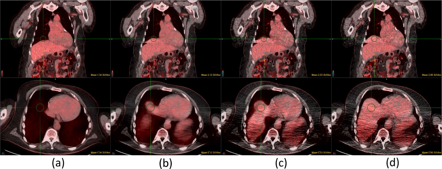
Case 15 of 18F-FDG study: (a) baseline PET/CT, (b) baseline PET/average CT, (c) DDG PET/D4D CT, and (d) DDG PET/DDG CT. All DDG PET, D4D CT, and DDG CT are in the EE phase. Top and bottom rows are the fusions of coronal and axial images, respectively. The SUVmean of a 3-cm diameter sphere is shown in each figure. DDG, data-driven gating
2.2 |. Average CT and DDG CT
Figure 1 shows a flowchart outlining the processing steps for the automated DDG CT. First, the average,3, 9 minimum (MIN), and maximum (MAX) intensity projection images were calculated. The average CT was derived from averaging of all cine CT images. The MIN and MAX images were derived from the minimum and maximum pixel values at the same pixel location across all cine CT images, respectively. The lung region was calculated according to the following steps: (1) thresholding the body region of ≥−350 HU containing the soft tissues, bones, and the higher intensities of the imaging table, and the regions of <−350 HU containing the lungs inside and the air space outside the body region, (2) removing the air space and the imaging table by a circular mask of 50 cm diameter, and (3) removing the small unconnected air space in the abdomen from the lung region with a 3D connected component analysis.37 The cine CT images associated with the largest and smallest average HU in the lung region were identified as the end-expiratory (EE) and EI images of DDG CT, respectively, based on the observation that the lung density decreases (increases) during inspiration (expiration) when the lung volume increases (decreases). For the image slices without any lung region present, the largest and smallest expansions of the body outline contour with a thresholding of −350 HU were selected to be the EE and EI phases, respectively. Finally, a consistency check was conducted to ensure the EE and EI phase images selected across the slice locations were acquired at the same time per cine CT step of 2 cm.
FIGURE 1.

Flowchart showing the data-processing steps for DDG CT. DDG, data-driven gating
The processing is fully automatic on a DDG CT server for seven GE PET/CT scanners spanning a 50-km radius of our hospital network. The DDG CT server can provide service to more scanners and was built on a desktop computer with all open-source software, including Ubuntu, DCMTK DICOM toolkit, and Python. Once the WB CT and cine CT are sent to the DDG server by the technologist. It will take about 1 and 3 min for the PET/CT scanner to receive average CT and DDG CT, respectively. As there is information specific to each scanner in the Dicom images, the server knows which scanner to receive the processed average CT and DDG CT.
Figure 2 shows the data flow from cine CT and WB CT to average CT and DDG CT. The average CT and EE phase of DDG CT is used for AC of baseline PET and DDG PET, respectively, after replacing the cine CT region of the baseline WB CT images. The EI phase is currently used for assessing the range of respiratory motion and not for AC of any PET data. In some cases when average CT was impacted by irregular respiration during the cine CT acquisition, EE phase DDG CT could be used for AC of baseline PET data in addition to DDG PET data. The utility of this application of the EE phase DDG CT will be discussed in more detail in Sections 3 and 4.
FIGURE 2.

Creation of average CT and DDG CT from both WB CT and cine CT. The same cine CT scan coverage in WB CT is replaced with average CT for AC of PET, and with DDG CT for AC of DDG PET. AC, attenuation correction; DDG, data-driven gating; WB, Whole body
2.3 |. Comparison of DDG CT with 4D CT and D4D CT
We compared the new DDG CT with the 4D CT and D4D CT images on 38 patient datasets acquired on a GE LightSpeed CT scanner with respect to respiratory phase image selection, lung HU, lung volume, and image artifacts. There were seven cine CT images per slice location and eight slice locations (8 × 2.5 mm = 2 cm) per cine CT step. Overall, cine CT scan coverage ranged from 14 to 18 cm, with 1, 2, and 35 patients having 9, 8, and 7 cine CT steps in their total scan coverage, respectively. The respiratory signals were recorded by the Varian RPM system during the cine CT scans for 4D CT, which tracks chest wall motion optically via an infrared reflector block placed on the patient’s abdomen between the umbilicus and xiphoid process. The peak and valley locations in the respiratory signals for each breath cycle were verified to match with the EI and EE phases, respectively, before correlation with the cine CT images for 4D CT.38 The verification step ensures the selections of 0% and 50% would match with the peak and valley locations of the respiratory signal, respectively. This is not typically done in 4D CT image selection. The same cine CT images were also processed by D4D, GE’s DDG CT application for radiotherapy. The 0% and 50% images of 4D CT and D4D CT were compared with the EI and EE phases of DDG CT, respectively. Currently, GE’s D4D CT application is only available for radiotherapy via CT simulators and not on other GE CT or PET/CT platforms.28
2.4 |. PET/CT acquisition
Four different GE Discovery PET/CT scanners: D690, D710, DR, and DMI were used in data acquisition. The DMI scanner has an AFOV of 25 cm, and the other three 15 cm. The injection activities for 18F-FDG, 68Ga-Dotatate, and 64Cu-Dotatate were targeted at 370, 185, and 185 MBq, respectively. The standard acquisition time per bed was 2 min for the DMI and 3 min for the other three scanners (5 min for 64Cu-Dotatate). The PET/CT acquisition protocol was identical to the clinical protocol.30 The images were reconstructed with OSEM, 2 iterations, and 18 subsets, time-of-flight, point spread function correction, standard z-axis filter, and post-reconstruction filter of 5-mm cutoff. GE’s Q.Static29 was used for all DDG-PET without any modifications. DDG PET data were derived from ~50% of the total PET data in the EE (quiescent) phase at 30% offset from the EI phase of each respiratory cycle. There was an increase in DDG PET image noise because it only retains 50% of the data used in routine PET. However, the increases in maximum standard uptake value (SUVmax) for tumors that are observed in our DDG PET/CT method originate from both motion correction (DDG PET) and improved registration from DDG CT rather than from the use of 50% of PET data.20
Finally, we also assessed the effects of CT AC for SUV in a separate group of 20 consecutive patient studies by comparing the following PET/CT combinations (PET/CT used for AC):(1) baseline PET/CT,(2) baseline PET/average CT, (3) DDG PET/D4D CT, and (4) DDG PET/DDG CT. This patient group only had a cine CT acquired in regions of misregistration, not 4D-CT like in the other 38 patient dataset. As a result, there were no respiratory signal-tracking data available from EDG using an RPM. The study was approved by the institutional review board, and patient consent was waived as all data were analyzed retrospectively.
2.5 |. Statistical analysis
The statistical differences between datasets were analyzed using one-way ANOVA, with GraphPad Prism 9.0 (GraphPad Software, San Diego, California, USA) and p < 0.01 was considered statistically significant.
3 |. RESULTS
3.1 |. Comparison of DDG CT, 4D CT, and D4D CT
Figure 3 shows the results of comparing DDG CT, 4D CT, and D4D CT for the selection of EE and EI respiratory phase images. In selecting the EE phase, DDG CT and 4D CT were identical in 62.5 ± 21.6% of the images, whereas DDG CT and D4D CT were 6.5 ± 9.7%, and 4D CT and D4D CT were 8.6 ± 12.2%. These differences in EE phase selection among the three gated CT methods were significant (p < 0.0001). When selecting the EI phase, DDG CT and 4D CT were identical in 68.2 ± 18.9% of the images, DDG CT and D4D CT were 63.9 ± 18.8%, and 4D CT and D4D CT were 61.2 ± 19.8%. These differences in EI phase identification were not significant. The average lung HU values for EE (EI) were −497 ± 73 (−530 ± 76), −497 ± 73 (−527 ± 77), −501 ± 76 (−530 ± 76) for DDG, 4D and D4D CT, respectively. The lung volumes for EE (EI) in liters were 1.85 ± 0.45 (2.29 ± 0.50), 1.87 ± 0.46 (2.28 ± 0.50), 1.95 ± 0.48 (2.26 ± 0.53) for DDG, 4D and D4D CT, respectively. The mean lung HU values and volumes were not statistically different (p > 0.1) among the three gated CT methods. This suggests that both global measures were not able to tell the three methods apart as the differences in the lower lungs or the upper liver tend to be local rather than global.
FIGURE 3.
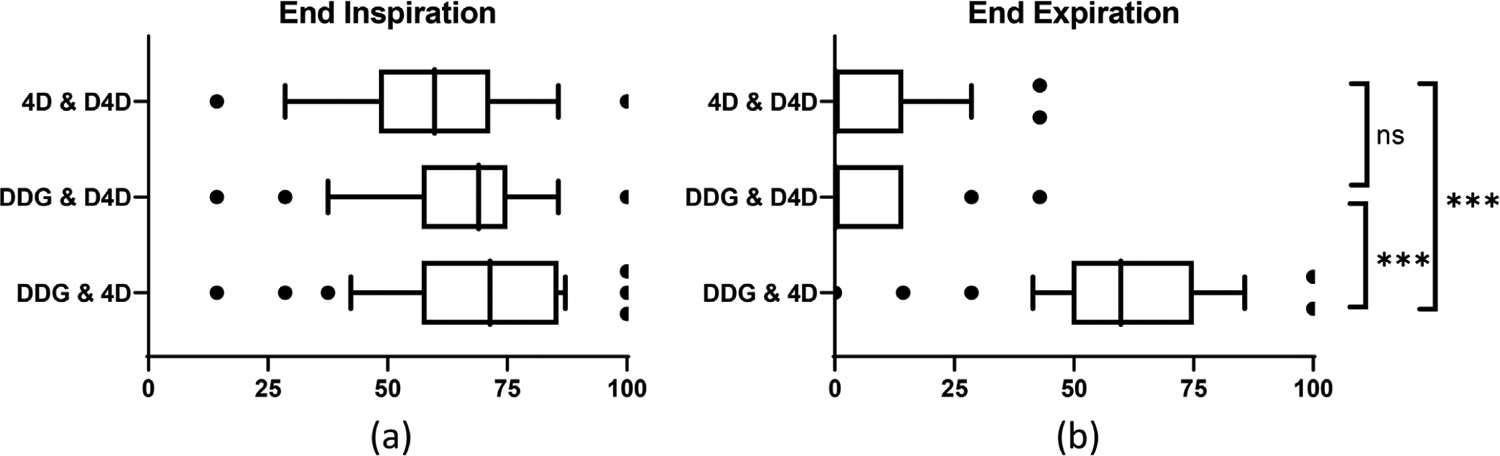
Comparison of DDG, D4D, and 4D CTs in the identification of EI (a) and EE (b) images from 38 patient studies. The x-axis indicates the percentage of the identical images selected by two of the three methods. There was no statistical difference between any two methods in the selection of EI images in (a). The agreement of DDG CT and 4D CT in the selection of EE images was statistically different from the agreement of either 4D CT and D4D CT, or DDG CT and D4D CT in (b). *** p < 0.0001. ns = not significant. DDG, data-driven gating; EE, end-expiratory; EI, end-inspiratory
In some studies, with irregular respiration, DDG was better than D4D in the selection of the EE and EI phases. In Figure 4, the respiratory signal as recorded by the RPM is in (a). Each rectangle in the plot at the bottom of the respiratory signal represents a single cine CT position (step) with an X-ray duration of 5 s. The 1.3-s pauses between cine CT positions are also visible in the plot. For this patient, an irregular respiration at the fifth position between 25 and 30 s of the cine CT scan is highlighted in red. Figure 4b and c corresponds to the CT (axial and sagittal views) for the fifth position where the irregular breath took place and then the next axial position, respectively. Also shown are the DDG CT, 4D CT, and D4D CT selections for EE (first three rows) and EI (last three rows) phases of each position. The EE phase of D4D CT (pointed to by an arrow) in Figure 4b at the fifth position with irregular breathing had a larger lung area than the EE phase of either DDG CT or 4D CT. It also had a larger lung area than the EI phase of D4D CT in Figure 4c, suggesting a reversal of EI and EE phases at the sixth position for D4D CT. On the other hand, the selected EE phase of DDG CT had a smaller lung area than the EE phase of D4D CT at both the fifth and sixth positions, as well as the EE phase of 4D CT at the sixth position in Figure 4c. These differences in EE and EI phase selections provide evidence that DDG CT was better than both 4D CT and D4D CT.
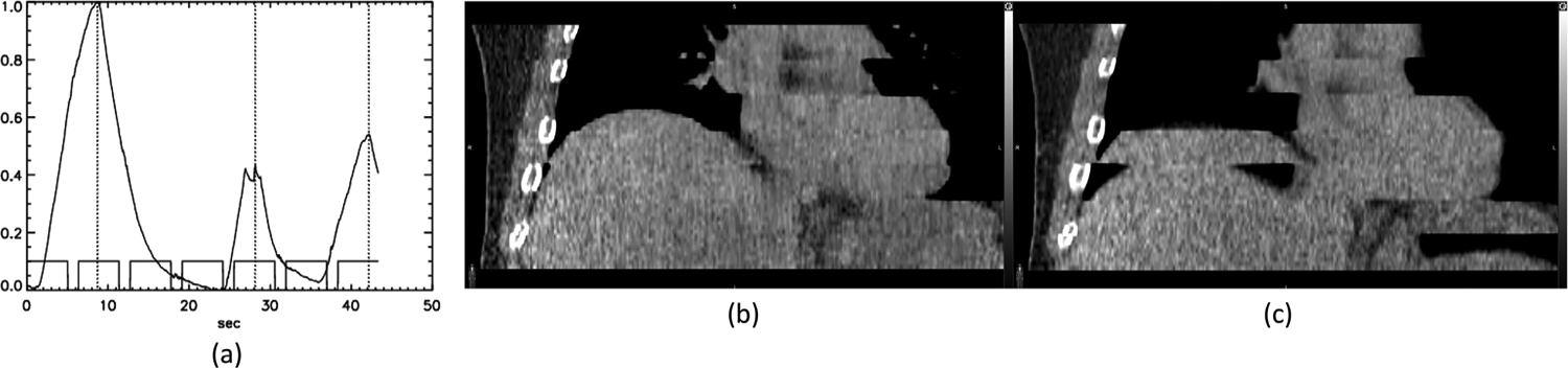
FIGURE 4.

(a) An irregular respiration at the fifth position during which no correct EI phase CT image was acquired. The images of the fifth and sixth positions are in (b) and (c), respectively. EI, end-inspiratory
Figure 5 shows another example of irregular breathing and has the same arrangement as Figure 4. This patient’s irregular respiration occurred at the fourth cine CT position between 19 and 24 s of the scan, with the amplitude of the EI phase significantly different from that at the next axial position (fifth position). The EE phase selected by D4D CT, highlighted by an arrow in Figure 5b, showed a very small liver size compared with the EE phase from DDG CT or 4D CT. This provides evidence that the EE phase of D4D CT was not selected correctly. In Figure 5c, the EI phase selected by DDG CT had a larger lung area than both 4D CT and D4D CT, again suggesting DDG CT was closer to the desirable EI phase than either 4D CT or D4D CT.
FIGURE 5.

(a) An irregular respiration at the fourth position of the scan during which the amplitude of the EI phase was very different from the one at the 5th position. The EE and EI images of the 4th and 5th positions are in (b) and (c), respectively. EE, end-expiratory and EI, end-inspiratory
Figure 6 shows an example where the average breath cycle was 16.7 s—significantly longer than the 5 s cine duration in the protocol. As seen in Figure 6b and c, DDG CT was better than average CT in maintaining the shape of the liver. Examination of the respiratory signal suggested that there was no correct EE phase CT image acquired in the second cine CT position, and that there were CT images close to the EE phase for all the other positions. DDG CT utilizing the EE phase may be more robust against irregular respiration than average CT.
FIGURE 6.
(a) A study with an average respiratory cycle duration of 16.7 s. DDG CT (b) was better than average CT (c) in maintaining the shape of the liver. DDG, data-driven gating. DDG, data-driven gating
3.2 |. Comparison of DDG CT and D4D CT for AC of DDG PET
Table 1 lists the SUV measurements of the 20 consecutive PET studies (1 64Cu-Dotatate, 5 68Ga-Dotatate and 14 18F-FDG), comparing values for baseline PET/CT, PET AC by average CT, DDG PET AC by D4D CT, and DDG PET AC by DDG CT. The first 14 cases were compared with SUVmax of a lesion except for case 5 where the measurement was on the myocardium. When there were multiple lesions, only the lesion with the largest percentage change in SUVmax from D4D to DDG CT was included. This tends to choose the lesion closest to the diaphragm. There were six studies (cases 15–20) without a lesion near the diaphragm—for these cases, the measurement was based on a 3-cm diameter sphere near the top of the liver and SUVmean was used instead of SUVmax.The increase in % SUV from D4D CT to DDG CT was tabulated in the last column.
TABLE 1.
SUV measurements of 20 consecutive studies comparing AC for DDG PET with D4D CT and DDG CT. Baseline PET/CT and PET AC by average CT are also included for reference. The first 14 cases were measured with SUVmax on a lesion except case 5 that was on the myocardium. The cases of 15 to 20 were measured with a 3-cm diameter at the top of the liver using SUVmean. There was a statistically significant difference among the means of PET AC by average CT, DDG PET AC by D4D CT, and DDG PET AC by DDG CT when normalized to baseline PET/CT (p = 0.0025)
| Case | Type | Baseline | PET/average CT | DDG PET/D4D CT | DDG PET/DDG CT | % SUV increase (D4D to DDG CT) |
|---|---|---|---|---|---|---|
| 1 | 68Ga-Dotatate | 29.6 | 28.7 | 34.1 | 41.2 | 20.9 |
| 2 | 68Ga-Dotatate | 4.7 | 8.2 | 16.9 | 18.6 | 9.9 |
| 3 | 68Ga-Dotatate | 18.5 | 22.2 | 26.2 | 28.6 | 9.2 |
| 4 | 68Ga-Dotatate | 15.8 | 17.2 | 24.3 | 26.3 | 8.3 |
| 5 | 18F-FDG | 8.1 | 9.7 | 9.2 | 9.9 | 7.9 |
| 6 | 18F-FDG | 7.1 | 7.5 | 8.6 | 9.2 | 7.5 |
| 7 | 18F-FDG | 3.3 | 6.5 | 10.1 | 10.8 | 7.4 |
| 8 | 18F-FDG | 2.4 | 2.8 | 3.5 | 3.7 | 7.2 |
| 9 | 18F-FDG | 4.5 | 6.7 | 8.9 | 9.4 | 6.1 |
| 10 | 18F-FDG | 8.4 | 9.5 | 8.9 | 9.3 | 4.0 |
| 11 | 18F-FDG | 1.9 | 1.8 | 2.1 | 2.2 | 3.7 |
| 12 | 68Ga-Dotatate | 15.6 | 22.3 | 27.0 | 27.5 | 2.0 |
| 13 | 18F-FDG | 14.0 | 17.2 | 29.2 | 29.6 | 1.4 |
| 14 | 18F-FDG | 4.7 | 7.1 | 15.8 | 16.0 | 1.2 |
| 15 | 18F-FDG | 1.1 | 1.8 | 2.4 | 2.9 | 21.2 |
| 16 | 18F-FDG | 0.8 | 1.4 | 1.9 | 2.2 | 15.5 |
| 17 | 18F-FDG | 1.1 | 2.6 | 2.9 | 3.1 | 7.6 |
| 18 | 18F-FDG | 3.2 | 3.2 | 7.5 | 7.6 | 1.5 |
| 19 | 64Cu-Dotatate | 3.6 | 6.1 | 7.4 | 7.5 | 1.5 |
| 20 | 18F-FDG | 1.0 | 1.3 | 2.2 | 2.2 | 0.9 |
Abbreviation: AC, attenuation correction; DDG, data-driven gating; SUV, standard uptake value.
There was an increase in SUV (either SUVmax or SUVmean) for all 20 cases when comparing DDG PET AC with DDG CT to DDG PET AC with D4D CT. These results suggest that DDG CT was better than D4D CT for accurate registration and optimal AC with DDG PET. All three methods of PET AC by average CT, DDG PET AC by D4D CT, and DDG PET AC by DDG CT were statistically different from each other (p = 0.0025).
Figure 7 shows case 1, with a lesion at the top of the liver. Only in Figure 7d with DDG PET AC by DDG CT is the lesion well registered in the liver, whereas in the other three methods shown in Figure 7a–c the lesion appeared in the lungs. This case maintained the largest increase in lesion SUVmax (21%) from improved AC for DDG PET by DDG CT relative to D4D CT. Figure 8 shows case 5, which had an increase in SUVmax of 7.9% on the myocardium, likely resulting from a better alignment between DDG PET and DDG CT than DDG PET and D4D CT. In addition, there was an empty space indicating a portion of the liver missing in D4D CT (coronal view) but not in DDG CT. Figure 9 shows case 6 with an increase in SUVmax of 7.5% for a liver lesion (coronal view), as well as an increase of 3.7% for another liver lesion with a necrotic center (axial view) that was clearly aligned better with DDG CT than with D4D CT. Figure 10 shows case 14, which had an increase in SUVmax of 1.2% with AC from DDG CT. The lesion was positioned slightly farther from the liver boundary in DDG CT than in D4D CT, suggesting DDG CT was closer to the EE phase than D4D CT. Figure 11 displays case 15, which illustrated a large increase in SUVmean of 21.2% at the top of the liver (case 15 had no lesion near the diaphragm). In both the coronal and axial images, more of the liver was present for DDG CT than in D4D CT, which clearly impacted SUV values near the lung/liver boundary.
FIGURE 7.

Case 1 of 68Ga-Dotatate study: (a) baseline PET/CT, (b) baseline PET/average CT, (c) DDG PET/D4D CT, and (d) DDG PET/DDG CT. All DDG PET, D4D CT and DDG CT are in the EE phase. Top and bottom rows are the fusions of coronal and axial images, respectively. The SUVmax values are included in all figures. The lesion outside the liver in (a)–(c) is inside the liver in (d). DDG, data-driven gating; EE, end-expiratory
FIGURE 8.

Case 5 of 18F-FDG study: (a) baseline PET/CT, (b) baseline PET/average CT, (c) DDG PET/D4D CT, and (d) DDG PET/DDG CT. All DDG PET, D4D CT and DDG CT are in the EE phase. Top and bottom rows are the fusions of coronal and axial images, respectively. The SUVmax values are included in all figures. The top portion of the liver was missing in (c) D4D CT but not in (d) DDG CT. DDG, data-driven gating
FIGURE 9.

Case 6 of 18F-FDG study: (a) baseline PET/CT, (b) baseline PET/average CT, (c) DDG PET/D4D CT, and (d) DDG PET/DDG CT. All DDG PET, D4D CT and DDG CT are in the EE phase. Top and bottom rows are the fusions of coronal and axial images, respectively. The SUVmax values are included in all figures. DDG, data-driven gating
FIGURE 10.

Case 14 of 18F-FDG study: (a) baseline PET/CT, (b) baseline PET/average CT, (c) DDG PET/D4D CT, and (d) DDG PET/DDG CT. All DDG PET, D4D CT, and DDG CT are in the EE phase. Top and bottom rows are the fusions of coronal and axial images, respectively. The SUVmax values are included in all figures. DDG, data-driven gating
The convention in radiotherapy is that 50% is generally recognized as the EE phase in 4D-CT applications.39, 40 The observed increases in SUV from the use of DDG CT for AC of DDG PET relative to D4D CT may indicate that D4D CT at 50% is not always the EE phase. As a result, searching for the EE phase over multiple series of D4D CT may enable a fair comparison with DDG CT. An attempt to address this issue by searching for the EE phase out of the range of 30%–80% is in Figure 12 from case 8, the collection of phases typically included for DDG PET.29 As seen in the top row of Figure 12, DDG CT was closest to the EE phase with the largest superior diaphragm position, followed by D4D CT at 40%, 50%–80% (all equivalent), and finally 30%. The 40% was the closest to the EE phase in the 10 phases of D4D CT but was not the expected EE phase as demonstrated by DDG CT. There was no information regarding which phase of D4D CT best represents the EE phase.28
FIGURE 12.
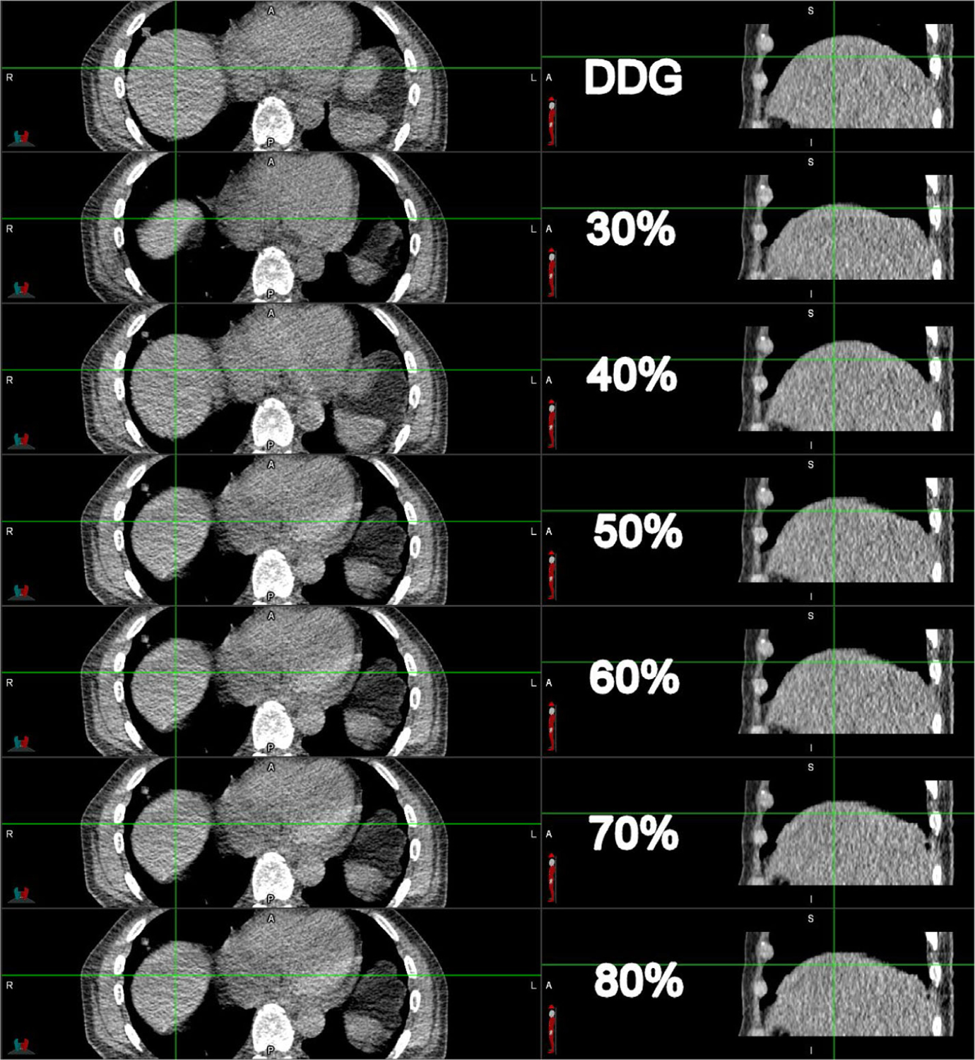
Comparison of DDG CT (top row) and D4D CT of 30% to 80% (second to seventh rows) for case 8. The axial and coronal views are on the left and right panels, respectively. The crosshair anchors the corresponding anatomy between the axial and coronal views. DDG, data-driven gating
3.3 |. Comparison of average CT and DDG CT for AC of baseline PET and DDG PET
Most of the time average CT and DDG CT are well registered with PET and DDG PET, respectively. However, when there is irregular respiration during the cine CT acquisition, average CT can be impacted more than DDG CT (see Figure 6). Of the 14 cases showing a lesion involved in the misregistration and/or lesion motion, 4 cases could benefit from using DDG CT at the EE phase for AC of baseline PET data. Figure 13 (case 4) shows a 68Ga-Dotatate study, and Figure 14 (case 14) an 18F-FDG study. In both figures, the images from left to right were three PET images with AC by baseline CT, average CT and DDG CT, and three DDG PET images with AC also by baseline CT, average CT and DDG CT. The irregular respiration or uneven averaging could degrade the average CT and led to poor registration and incorrect SUV in Figure 14b but did not impact PET AC by DDG CT in Figure 14c, which was from one single image closest to EE. The degradation of average CT was likely due to more inspiration than expiration in the 5 s cine CT acquisition for averaging. For example, the 5 s duration could consist of two EI phases but only one EE phase. DDG CT was not impacted by this effect. That is why DDG CT could be used to replace average CT when there is misregistration between PET and average CT. As there was no recording of the respiratory signal to correlate with the cine CT images in the second set of 20 cases, we could only compare the DDG EE and average CT images to suggest a potential root cause. Similar effects of improved registration can be seen in DDG PET with AC of baseline CT, average CT to DDG CT. It was clear from the two examples that registration between CT and PET and gating of CT and/or PET tended to increase SUV of the lesions.
FIGURE 13.

Case 4 of 68Ga-Dotatate study: (a) baseline PET/CT, (b) baseline PET/average CT, (c) baseline PET/DDG CT, (d) DDG PET/baseline CT, (e) DDG PET/average CT, and (f) DDG PET/DDG CT. Top and bottom rows are the fusions of coronal and axial images, respectively. The SUVmax values are in the top panel. DDG, data-driven gating
FIGURE 14.

Case 14 of 18F-FDG study: (a) baseline PET/CT, (b) baseline PET/average CT, (c) baseline PET/DDG CT, (d) DDG PET/baseline CT, (e) DDG PET/average CT and (f) DDG PET/DDG CT. Top and bottom rows are the fusions of coronal and axial images, respectively. The SUVmax values are in the top panel. DDG, data-driven gating
4 |. DISCUSSION
Both methods for gated CT analyzed in this work (DDG CT and D4D CT) were based on lung HU, and body outline contours for the selection of EE and EI phase images from cine CT data. DDG CT and the clinical standard 4D CT were identical in 62.5 ± 21.6% of the EE images and 68.2 ± 18.9% of the EI images in a cohort of 38 patient datasets. On the other hand, only 8.6 ± 12.2% of the EE images and 61.2 ± 19.8% of the EI images are identical between 4D CT and D4D CT. It was also shown in Figures 4 and 5 that the EE or EI phases were better selected by DDG CT than 4D CT when there was a discrepancy between DDG CT and 4D CT. Additionally, D4D CT could reverse the EE and EI phases around the diaphragm area (see Figure 4c) or not select the correct images for the EE or EI phase (see Figure 5b and c). Although overall lung mean HU or lung volumes were not statistically different, DDG CT appeared to be better than 4D CT or D4D CT in the lower lung and upper diaphragm regions where misregistration and tumor motion tend to occur. One design feature of D4D CT was its attempt to remove image artifacts appearing in the transition between two cine positions in the situation of irregular respiration (see Figures 4 and 5). D4D CT will make a smooth transition by replacing very dissimilar images with the ones that are more similar in order to minimize image artifacts between two cine positions. This artifact removal could give the user a false impression that the study was not impacted by the irregular respiration(s) even though it was. Furthermore, it could also lead to incorrect selection of EE or EI phases in D4D CT, which impacts registration and PET quantification as shown in this work.
From the analysis of 20 DDG PET/CT studies when both PET and CT were gated, the idea that DDG CT was better than D4D CT in the selection of the EE phase was further supported by an increase in SUVmax of lesions near the diaphragm or SUVmean at the top of the liver. DDG CT also enabled improved registration of the functional tumor and underlining anatomy when compared to D4D CT. Although there were about eight cases with <5% difference in SUV for AC of the DDG PET between D4D CT and DDG CT, we did not observe a single case where D4D CT was better aligned with DDG PET than DDG CT. This further solidifies the more reliable selection of EE phase CT images by DDG CT than D4D CT. In addition, there was a possibility that D4D CT may not succeed in capturing the EE phase among a wide range of phases from the full cine CT data. This observation is noteworthy even though manually searching for the best phase in routine clinical data is not practical.
Current vendor options for average CT or gated CT require EDG CT,8 which can be realized with either cine CT (GE) or helical CT (Siemens, Philips, Canon, etc.) scan modes.41, 42 D4D CT is currently only available for GE’s Radiotherapy simulation CT, not any of GE’s PET/CT applications. As a result, any attempt to match CT with DDG PET will be through 4D-CT, which requires a Varian RPM for gating. This is not compatible with DDG PET, which does not require the RPM device. In our implementation, we derive DDG CT from the same cine CT that is used to obtain average CT. This cine CT option is available on all GE PET/CT scanners and is not tied to any specific application. This makes our design, which embeds a limited scan coverage of average CT or DDG CT into a WB CT (see Figure 2), possible on all GE scanners. Siemens has recently prototyped a cine CT for their prospective 4D CT,43 which could enable our approach on their PET/CT scanners.
Just like in WB PET/CT, the quality of average CT can be impacted by irregular respiration. Because cine CT data is acquired for 5 s per location, DDG CT at the EE phase, unlike average CT, is less likely to be impacted by irregular respiration. As a result, EE phase DDG CT can substitute average CT for AC of baseline PET data as demonstrated in Figures 6, 13, and 14.
One disadvantage of DDG CT or D4D CT was the noisy appearance of their images because they are selected from only one of the cine CT images as opposed to the average CT from averaging of all cine CT images. The noise problem can be made worse in cine CT scans where both arms of the patient are kept down and by the side of the body. An example of this is reflected in Figure 11, with severe streaking artifacts due to low photon flux to penetrate a patient with an above-average body mass index (31.4). These issues may be mitigated with an increased radiation dose in the cine CT acquisition or use of noise reduction software in CT reconstruction. Other ways to improve the noise characteristics of DDG CT will be important to study and implement in order to improve the image quality of fused PET/CT images.
In this work, we reported lesion quantification measurements in terms of SUVmax. Using only 50% of counts for DDG PET can certainly impact SUVmax. But the increased noise from reduced counts is not guaranteed to increase SUVmax. We have found and reported previously that reducing counts by 50% does not bias SUV. Instead, it can increase or decrease SUVmax. For instance, we found that both motion correction and improved AC (either average CT or DDG CT) increased SUVmax above any amount expected from noise with 50% reduced counts.20 Separating the combined effects of motion correction, noise from reduced counts, and improved AC with DDG CT is not straightforward and would be part of other separate work, which is currently taking place. The focus of this work was primarily to compare DDG CT with 4D-CT and D4D CT, where this issue of noise effects on SUVmax is not critical.
The concept of DDG PET/CT was proposed over a decade ago,35 and was designed as an independent scan after WB PET/CT with a long acquisition time to suppress noise for DDG PET data, and without average CT. Its cine CT radiation dose was 5 mSv, almost 4 times higher than the radiation dose associated with our current DDG PET/CT application (1.3 ± 0.6 mSv).44 In our protocol, DDG PET is derived directly from the WB PET data, without a change in PET acquisition times, and the cine CT is acquired only to cover the area of misregistration in a multiple of 2 cm instead of an entire PET bed AFOV.35 This strategy improves patient comfort and avoids a long-duration PET scan in the repeat PET/CT. The disadvantage of additional radiation dose with our DDG CT is noted. However, this radiation dose is relatively small compared to that from the baseline WB PET/CT of about 10 mSv.36 The proposed acquisition protocol, in which average CT and DDG CT are generated from the same cine CT for AC of baseline PET and DDG PET, respectively, is practical and has been successfully integrated with our clinical routine to tackle both issues of misregistration and tumor motion. More than 100 DDG PET/CT studies have been conducted in our institution with this design for DDG CT.
5 |. CONCLUSION
A new automatic DDG CT method was developed to address issues of both tumor motion and misregistration in PET/CT imaging. DDG CT was significantly more consistent than D4D CT in selecting the EE phase images as the clinical standard of 4D CT. When compared to both commercial gated CT methods of 4D CT and D4D CT, DDG CT appeared to be more robust in the lower lung and upper diaphragm regions where misregistration and tumor motion often occur. In cases where irregular respiratory motion complicated proper phase identification, DDG CT offered improved AC for DDG PET relative to D4D CT. When average CT was impacted by irregular respiration or very long respiration cycles, DDG CT also provided improved AC over average CT for baseline PET. The new DDG CT does not alter clinical workflows because it does not require an external tracking device, yet provides the same benefits for PET/CT imaging as traditional external device 4D CT.
ACKNOWLEDGMENTS
The authors would like to thank the clinical PET/CT technologists in M.D. Anderson for acquiring the data for this study. This research was supported in part by National Institutes of Health grants R21-CA222749-01A1, R03-EB030280-01, R01-HL157273-01, and a ROSI grant from M.D. Anderson, Division of Radiation Oncology. This research was conducted at the M.D.Anderson Center for Advanced Biomedical Imaging in part with equipment support from GE Healthcare.
Funding information
National Institutes of Health, Grant/Award Numbers: R21-CA222749-01A1, R03-EB030280-01, R01-HL157273-01
Footnotes
CONFLICT OF INTEREST
Tinsu Pan Consultant of Bracco Medical Inc.
REFERENCES
- 1.Reinert CP, Sekler J, laFougere C, Pfannenberg C, Gatidis S. Impact of PET/CT on clinical management in patients with cancer of unknown primary-a PET/CT registry study. Eur Radiol. 2020;30(3):1325–1333. [DOI] [PubMed] [Google Scholar]
- 2.Czernin J, Allen-Auerbach M, Nathanson D, Herrmann K. PET/CT in oncology: current status and perspectives. Curr Radiol Rep. 2013;1:177–190. [DOI] [PMC free article] [PubMed] [Google Scholar]
- 3.Pan T, Mawlawi O, Nehmeh SA, et al. Attenuation correction of PET images with respiration-averaged CT images in PET/CT. J Nucl Med. 2005;46(9):1481–1487. [PubMed] [Google Scholar]
- 4.Hamill JJ, Meier JG, Betancourt Cuellar SL, Sabloff B, Erasmus JJ, Mawlawi O. Improved alignment of PET and CT images in whole-body PET/CT in cases of respiratory motion during CT. J Nucl Med. 2020;61(9):1376–1380. [DOI] [PubMed] [Google Scholar]
- 5.Nehmeh SA, Erdi YE, Pan T, et al. Four-dimensional (4D) PET/CT imaging of the thorax. Med Phys. 2004;31(12):3179–3186. [DOI] [PubMed] [Google Scholar]
- 6.Nehmeh SA, Erdi YE, Pan T, et al. Quantitation of respiratory motion during 4D-PET/CT acquisition. Med Phys. 2004;31(6):1333–1338. [DOI] [PubMed] [Google Scholar]
- 7.Werner MK, Parker JA, Kolodny GM, English JR, Palmer MR. Respiratory gating enhances imaging of pulmonary nodules and measurement of tracer uptake in FDG PET/CT. AJR Am J Roentgenol. 2009;193(6):1640–1645. [DOI] [PubMed] [Google Scholar]
- 8.Pan T, Lee TY, Rietzel E, Chen GT. 4D-CT imaging of a volume influenced by respiratory motion on multi-slice CT. Med Phys. 2004;31(2):333–340. [DOI] [PubMed] [Google Scholar]
- 9.Pan T, Mawlawi O, Luo D, et al. Attenuation correction of PET cardiac data with low-dose average CT in PET/CT. Med Phys. 2006;33(10):3931–3938. [DOI] [PubMed] [Google Scholar]
- 10.Hamill J, Panin V, TOF-MLAA for attenuation correction in thoracic PET/CT. IEEE Nuclear Science Symposium Conference Record; 2012:4041–4047. [Google Scholar]
- 11.Rezaei A, Deroose CM, Vahle T, Boada F, Nuyts J. Joint reconstruction of activity and attenuation in time-of-flight PET: a quantitative analysis. J Nucl Med. 2018;59(10):1630–1635. [DOI] [PMC free article] [PubMed] [Google Scholar]
- 12.Lu Y, Fontaine K, Mulnix T, et al. Respiratory motion compensation for PET/CT with motion information derived from matched attenuation-corrected gated PET data. J Nucl Med. 2018;59(9):1480–1486. [DOI] [PMC free article] [PubMed] [Google Scholar]
- 13.He J, O’Keefe GJ, Gong SJ, et al. Device-less gating for PET/CT using PCA. IEEE Trans Nucl Sci. 2008;55(5):2557–2565. [Google Scholar]
- 14.Feng T, Wang J, Sun Y, Zhu W, Dong Y, LiH. Self-Gating: an adaptive center-of-mass approach for respiratory gating in PET. IEEE Trans Med Imaging. 2018;37(5):1140–1148. [DOI] [PubMed] [Google Scholar]
- 15.Buther F, Jones J, Seifert R, Stegger L, Schleyer P, Schafers M. Clinical evaluation of a data-driven respiratory gating algorithm for whole-body PET with continuous bed motion. J Nucl Med. 2020;61(10):1520–1527. [DOI] [PubMed] [Google Scholar]
- 16.Walker MD, Morgan AJ, Bradley KM, McGowan DR. Data-driven respiratory gating outperforms device-based gating for clinical (18)F-FDG PET/CT. J Nucl Med. 2020;61(11):1678–1683. [DOI] [PMC free article] [PubMed] [Google Scholar]
- 17.Callahan J, Kron T, Schneider-Kolsky M, Hicks RJ. The clinical significance and management of lesion motion due to respiration during PET/CT scanning. Cancer Imaging. 2011;11:224–236. [DOI] [PMC free article] [PubMed] [Google Scholar]
- 18.Hong I, Jones J, Hamill J, Michel C, Casey M, Elastic motion correction for continuous bed motion whole-body PET/CT. Paper presented at: 2016 IEEE Nuclear Science Symposium, Medical Imaging Conference and Room-Temperature Semiconductor Detector Workshop (NSS/MIC/RTSD); 2016. [Google Scholar]
- 19.Hong I, Jones J, Casey M, Elastic motion correction for continuous bed motion whole-body PET/CT. Paper presented at: 2014 IEEE Nuclear Science Symposium, Medical Imaging Conference (NSS/MIC); 2014. [Google Scholar]
- 20.Thomas MA, Pan T. Data-driven gated PET/CT: implications for lesion segmentation and quantitation. EJNMMI Phys. 2021;8(1):64. [DOI] [PMC free article] [PubMed] [Google Scholar]
- 21.Pan T, Lee TY, Rietzel E, Chen GTY. 4D-CT imaging of a volume influenced by respiratory motion on multi-slice CT. Med Phys. 2004;31(2):333–340. [DOI] [PubMed] [Google Scholar]
- 22.Li R, Lewis JH, Cervîo LI, Jiang SB. 4D CT sorting based on patient internal anatomy. Phys Med Biol. 2009;54(15):4821–4833. [DOI] [PubMed] [Google Scholar]
- 23.Hui C, Suh Y, Robertson D, et al. Internal respiratory surrogate in multislice 4D CT using a combination of Fourier transform and anatomical features. Med Phys. 2015;42(7):4338–4348. [DOI] [PubMed] [Google Scholar]
- 24.Carnes G, Gaede S, Yu E, Van Dyk J, Battista J, Lee T-Y. A fully automated non-external marker 4D-CT sorting algorithm using a serial cine scanning protocol. Phys Med Biol. 2009;54(7):2049–2066. [DOI] [PubMed] [Google Scholar]
- 25.Xu S, Taylor RH, Fichtinger G, Cleary K. Lung deformation estimation and four-dimensional CT lung reconstruction. Acad Radiol. 2006;13(9):1082–1092. [DOI] [PubMed] [Google Scholar]
- 26.Zeng R, Fessler JA, Balter JM, Balter PA. Iterative sorting for four-dimensional CT images based on internal anatomy motion. Med Phys. 2008;35(3):917–926. [DOI] [PMC free article] [PubMed] [Google Scholar]
- 27.Martin R, Pan T. Target volume and artifact evaluation of a new data-driven 4D CT. Pract Radiat Oncol. 2017;7(5):e345–e354. [DOI] [PubMed] [Google Scholar]
- 28.Smart Deviceless 4D. White Paper, GE Healthcare. 2015:1–6. [Google Scholar]
- 29.Khamis H, Wollenweber S, MotionFree: device-less digital respiratory gating technology, seamlessly integrated in PET imaging routine. White Paper, GE Healthcare. 2019:1–12. [Google Scholar]
- 30.Pan T, Lu Y, Thomas MA, Liao Z, Luo D. New data-driven gated PET/CT free of misregistration artifacts. Int J Radiat Oncol Biol Phys. 2021;109(5):1638–1646. [DOI] [PMC free article] [PubMed] [Google Scholar]
- 31.Chi P-CM, Balter P, Luo D, Mohan R, Pan T. Relation of external surface to internal tumor motion studied with cine CT. Med Phys. 2006;33(9):3116–3123. [DOI] [PubMed] [Google Scholar]
- 32.Low DA, Nystrom M, Kalinin E, et al. A method for the reconstruction of four-dimensional synchronized CT scans acquired during free breathing. Med Phys. 2003;30(6):1254–1263. [DOI] [PubMed] [Google Scholar]
- 33.Rodriguez-Molinero A, Narvaiza L, Ruiz J, Galvez-Barron C. Normal respiratory rate and peripheral blood oxygen saturation in the elderly population. J Am Geriatr Soc. 2013;61(12):2238–2240. [DOI] [PubMed] [Google Scholar]
- 34.Xia T, Alessio AM, Kinahan PE, Limits of ultra-low dose CT attenuation correction for PET/CT. IEEE Nucl Sci Symp Conf Rec (1997). 2010;2009(Oct. 24 2009–Nov. 1 2009):3074–3079. [DOI] [PMC free article] [PubMed] [Google Scholar]
- 35.Schleyer PJ, O’Doherty MJ, Barrington SF, Marsden PK. Retrospective data-driven respiratory gating for PET/CT. Phys Med Biol. 2009;54(7):1935–1950. [DOI] [PubMed] [Google Scholar]
- 36.Brix G, Lechel U, Glatting G, et al. Radiation exposure of patients undergoing whole-body dual-modality 18F-FDG PET/CT examinations. J Nucl Med. 2005;46(4):608–613. [PubMed] [Google Scholar]
- 37.Grana C, Borghesani D, Cucchiara R. Optimized block-based connected components labeling with decision trees. IEEE Trans Image Process. 2010;19(6):1596–1609. [DOI] [PubMed] [Google Scholar]
- 38.Pan T, Sun X, Luo D. Improvement of the cine-CT based 4D-CT imaging. Med Phys. 2007;34(11):4499–4503. [DOI] [PubMed] [Google Scholar]
- 39.Tehrani JN, Yang Y, Werner R, et al. Sensitivity of tumor motion simulation accuracy to lung biomechanical modeling approaches and parameters. Phys Med Biol. 2015;60(22):8833–8849. [DOI] [PMC free article] [PubMed] [Google Scholar]
- 40.Yaegashi Y, Tateoka K, Nakazawa T, et al. Analysis of the optimum internal margin for respiratory-gated radiotherapy using end-expiratory phase assessments using a motion phantom. J Appl Clin Med Phys. 2012;13(2):3715. [DOI] [PMC free article] [PubMed] [Google Scholar]
- 41.Keall PJ, Starkschall G, Shukla H, et al. Acquiring 4D thoracic CT scans using a multislice helical method. Phys Med Biol. 2004;49(10):2053–2067. [DOI] [PubMed] [Google Scholar]
- 42.Pan T. Comparison of helical and cine acquisitions for 4D-CT imaging with multislice CT. Med Phys. 2005;32(2):627–634. [DOI] [PubMed] [Google Scholar]
- 43.Werner R, Sentker T, Madesta F, et al. Intelligent 4D CT sequence scanning (i4DCT): first scanner prototype implementation and phantom measurements of automated breathing signal-guided 4D CT. Med Phys. 2020;47(6):2408–2412. [DOI] [PubMed] [Google Scholar]
- 44.Pan T, Lu Y, Thomas MA, Liao Z, Luo D. New data-driven gated PET/CT free of misregistration artifacts. Int J Radiat Oncol Biol Phys. 2020;109:1638–1646. [DOI] [PMC free article] [PubMed] [Google Scholar]