Abstract
In recent years, golden‐angle radial sampling has received substantial attention and interest in the magnetic resonance imaging (MRI) community, and it has become a popular sampling trajectory for both research and clinical use. However, although the number of relevant techniques and publications has grown rapidly, there is still a lack of a review paper that provides a comprehensive overview and summary of the basics of golden‐angle rotation, the advantages and challenges/limitations of golden‐angle radial sampling, and recommendations in using different types of golden‐angle radial trajectories for MRI applications. Such a review paper is expected to be helpful both for clinicians who are interested in learning the potential benefits of golden‐angle radial sampling and for MRI physicists who are interested in exploring this research direction. The main purpose of this review paper is thus to present an overview and summary about golden‐angle radial MRI sampling. The review consists of three sections. The first section aims to answer basic questions such as: what is a golden angle; how is the golden angle calculated; why is golden‐angle radial sampling useful, and what are its limitations. The second section aims to review more advanced trajectories of golden‐angle radial sampling, including tiny golden‐angle rotation, stack‐of‐stars golden‐angle radial sampling, and three‐dimensional (3D) kooshball golden‐angle radial sampling. Their respective advantages and limitations and potential solutions to address these limitations are also discussed. Finally, the third section reviews MRI applications that can benefit from golden‐angle radial sampling and provides recommendations to readers who are interested in implementing golden‐angle radial trajectories in their MRI studies.
Evidence Level
5
Technical Efficacy
Stage 1
Keywords: golden‐angle, radial sampling, stack‐of‐stars, continuous acquisition, self‐navigation, motion robustness
Magnetic resonance imaging (MRI) is a powerful and diverse imaging modality used in our day‐to‐day clinical practice. Today, majority of clinical MR images are acquired using a Cartesian sampling trajectory. An example of 2D Cartesian trajectory with five phase‐encoding measurements is shown in Fig. 1a, with which MR measurements (also known as k‐space lines) are collected in a sequential line‐by‐line manner to fill in a Cartesian grid (five k‐space lines in this example). When the Nyquist sampling rate is satisfied for k‐space acquisition, a fast Fourier transform (FFT) can be performed to reconstruct an MR image. In recent years, radial sampling has captured substantial attention and interest in the MRI community. For those who are not familiar with radial sampling, it has a long history in MRI and was the trajectory implemented by Lauterbur in his seminal work published in 1973. 1 Figure 1b shows a simple 2D radial sampling trajectory with five phase‐encoding measurements that are rotated linearly. Instead of collecting k‐space lines in a parallel scheme as in the Cartesian trajectory, radial sampling collects k‐space lines in a star shape, and each radial k‐space line (referred to as a radial spoke or simply spoke) passes through the center of k‐space. Similar to Cartesian sampling, all the rotating radial spokes are also acquired line‐by‐line sequentially but with overlapping around the center of k‐space. These radial k‐space measurements can then be processed to reconstruct an MR image (see the subsequent section for details). This unique sampling scheme offers flexibility to design how those radial spokes are rotated from one to the next. To date, the most well‐known and most often used rotation scheme is golden‐angle radial sampling, 2 in which radial spokes are rotated by a so‐called “golden angle” (e.g. 111.25° for 2D radial sampling).
FIGURE 1.
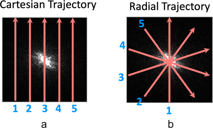
Comparison of 2D Cartesian sampling (a) with 2D radial sampling (b). Cartesian sampling acquires parallel k‐space lines on a Cartesian grid. Radial sampling acquires k‐space lines in a star shape. Each radial k‐space spoke has a different orientation and passes through the center of k‐space. The sampling density of radial acquisition is higher around the center than the periphery.
Despite substantial interest, researchers often ask some questions like: what is a golden angle; why is it 111.25°; why is it interesting; and where does this angle come from? Several related questions include: how many golden angles do we have; what are the advantages of golden‐angle radial sampling and when should we use it; are there any challenges in using it compared to traditional Cartesian sampling? Meanwhile, many vendors have already made their (golden‐angle) radial MRI sequence as a product or are planning to make it in near future, and this sampling trajectory is seeing more and more clinical applications today. Therefore, there is a pressing need to have a comprehensive review article that summarizes the basics of golden‐angle radial sampling, particularly for those with a more clinically focused background. The purpose of this review article is to meet this need. It aims to shed more light on the basics and advantages of golden‐angle radial sampling, to discuss its limitations and potential solutions for overcoming them, and also to provide suggestions in using this sampling strategy in practical MRI applications.
This article is organized as three sections. In the first section, the basics of golden‐angle radial sampling, including its advantages and limitations, are described. In the second section, more advanced discussion about golden‐angle radial sampling, including its extension and variants, are discussed. The last section focuses on potential clinical applications of golden‐angle radial sampling and recommendations for implementing different types of golden‐angle radial trajectories in practical MRI studies.
Basics of Golden‐Angle Radial Sampling
This section first guides the readers to derive the golden angle and shows where the angle (e.g. 111.25°) comes from. This is followed by discussion about the general advantages and limitations of golden‐angle radial sampling (focusing on 2D golden‐angle radial sampling). Although we are specifically discussing golden‐angle radial sampling here, many of these features are expected to be similar for different types of radial trajectories, including 2D radial and three‐dimensional (3D) radial sampling with or without golden‐angle rotation.
Golden Angle: How Do We Derive It?
THE GOLDEN RATIO
Derivation of the golden angle is based on the concept of golden ratio (GR). 3 As shown in Fig. 2a, in a line with two segments, the ratio equals the GR if . Solving this equation leads to the GR of . The GR is also known as the golden section, and it has been widely used in our daily life, including architecture, art, book, and music. The inverse of the GR is called the 1D golden mean. 4
FIGURE 2.
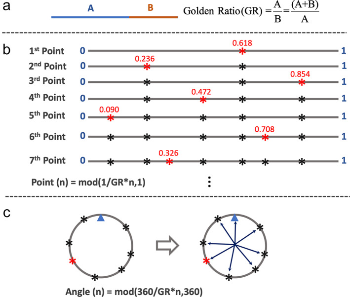
(a) In a line with two segments, the ratio of A and B () is defined as the golden ratio when . This ratio ≈1.618. (b) A line with the length of 1 is successively divided into smaller segments by the golden ratio. The position of the nth point can be expressed as . It can be seen that each new point always cut the largest segment of the line by the golden ratio, and the points have a roughly uniform distribution on the line. (c) When the seventh line in (b) is bended to connect as a circle, these points also have a roughly uniform distribution on the circle. The small blue triangle in (c) indicates the location where the start and the end positions of the line are connected. The angle of each point can then be calculated as , and the golden angle is ~137.51°.
CUTTING A LINE BY THE GOLDEN RATIO
Figure 2b shows how a line can be cut by the GR. Here, a line with length 1 is successively divided into smaller segments by the GR. The position of the nth point can be expressed as follows:
| (1) |
where 1 indicates the length of the line and mod(a,1) returns [a − floor(a)]. It can be seen that each new point always cuts the largest segment of the line by the GR, and all the points tend to have a roughly uniform distribution on the line.
CUTTING A CIRCLE BY THE GOLDEN RATIO
When the seventh line in Fig. 2b is bended to connect as a circle, these points also have a roughly uniform distribution on the circle, as shown in Fig. 2c. The small blue triangle here indicates the point where the start and the end positions of the line are connected. In this case, instead of cutting a line with length 1, these points successively cut a 360° circle based on the GR. As a result, Eq. 1 can be adapted to Eq. 2 to calculate the angle of each point heading toward the center.
| (2) |
The angle in Eq. 2, defined as is called a golden angle. To make smaller gradient switching in MRI, ~137.51° (360°–222.49°) is often used. Setting these points as the end positions of different lines starting from the center of the circle, we have a total of eight lines rotated by the golden angle given above, as shown in Fig. 2c.
HALF‐SPOKE GOLDEN‐ANGLE RADIAL SAMPLING
Based on the golden angle of ~137.51°, a golden‐angle radial trajectory can be designed as shown in Fig. 3a. Here, each line (a radial spoke) starts from the center, and the nth spoke rotates from the previous one by ~137.51°. It can be seen that each new spoke always fills the largest gap of the previous coverage by the GR, and all spokes never repeat each other. For this sampling trajectory, the first spoke is typically sampled at 0°, and the angle of the nth spoke is calculated as follows:
| (3) |
This trajectory corresponds to half radial spoke sampling in MRI, since each spoke starts from the center.
FIGURE 3.
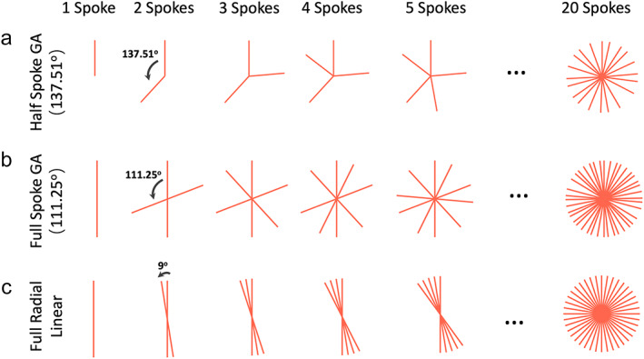
(a) Based on the points on a circle shown in Fig. 2c and corresponding golden angle, a radial trajectory can be designed. Here, each radial spoke starts from the center and the nth spoke rotates from the (n‐1)th spoke by a golden angle of ~137.51°. (b) When full radial spokes are acquired, one just needs to cover 180° to sample a full circle. The golden angle then becomes 180°/GR ≈ 111.25°. (c) For comparison, to sample a radial k‐space with 20 full radial spokes using standard linear ordering, each spoke rotates by an angle of 180°/20 = 9°.
FULL‐SPOKE GOLDEN‐ANGLE RADIAL SAMPLING
When full radial spokes are acquired, we only need to rotate the spokes for half of the circle (180°) to cover the entire 360° circle, as shown in Fig. 3b. In this case, the golden angle becomes 180°/GR ≈ 111.25°, and the angle of each spoke is then given as:
| (4) |
This trajectory corresponds to full radial spoke sampling in MRI, since each spoke starts from one side to the other side.
SUMMARY OF THE GOLDEN ANGLE
This section demonstrates how to derive the golden angle based on the GR. It should be noted that there are different golden angles depending on how radial spokes are sampled (e.g. half spoke or full spoke). In practice, the angle of ~111.25° is used more often because it gives more efficient k‐space coverage. Half‐spoke sampling is often used when we want to minimize the echo time (TE) in specific applications, such as in lung MRI. 5 For comparison, radial sampling with standard linear rotation is shown in Fig. 3c. While the golden‐angle rotation offers very uniform coverage through time, the linear rotation does not, and this is one of the main advantages to perform golden‐angle radial MRI as will be described more in the following subsection.
Advantages of Golden Angle Radial Sampling
The unique geometry of golden‐angle radial sampling offers several nice advantages for MRI applications, including improved robustness to motion compared to standard Cartesian sampling, incoherent undersampling behavior that can be synergistically combined with sparse MRI reconstruction, and continuous data acquisition with flexible data sorting. In addition, radial sampling also offers self‐navigation that can be exploited to improve motion management.
MOTION ROBUSTNESS
Cartesian sampling is known to be prone to motion‐induced artifacts, as shown in Fig. 4a (top row) for two examples, one in axial orientation and one in coronal orientation. Respiratory motion is indeed one of the primary resources of motion artifacts in MRI, 7 and it can cause image blurring and ghosting artifacts. Radial sampling, in contrast, has much higher robustness to motion, 6 , 8 , 9 , 10 , 11 , 12 as shown in Fig. 4a (bottom row) for comparing examples.
FIGURE 4.
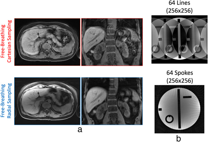
(a) In the presence of motion, Cartesian sampling generates ghosting artifacts, while radial sampling generates blurring. When imaging is performed in the axial plane, radial sampling is more robust to motion. (b) Radial sampling has higher incoherent undersampling behavior compared to Cartesian sampling. Undersampling a 2D Cartesian trajectory is typically performed along the phase‐encoding dimension only, and this leads to aliasing artifacts that spread along the phase encoding dimension. Undersampling a radial trajectory effectively enable acceleration along two spatial dimensions, which generates artifacts that spread along varying directions.
The improved motion robustness of radial sampling arises from the following two features. First, different from Cartesian sampling that has a fixed phase‐encoding direction, radial sampling has a varying phase‐encoding direction. Since motion‐induced artifacts mainly occur along the phase‐encoding direction, those artifacts can be distributed to varying directions in radial images and become less noticeable. Second, since each spoke passes through the center of k‐space in radial sampling, all the spokes carry an equal amount of information. Therefore, even if some k‐space measurements are corrupted by motion, other measurements can still compensate for it with an averaging effect. Such a sampling scheme substantially reduces the influence from motion.
Although radial sampling is less sensitive to motion, it is not free of motion artifacts. The main effect caused by motion in radial imaging is blurring, and large motion can cause severe blurring. From the examples shown in Fig. 4a, we can also see that the axial radial image has less blurring than the coronal radial image. This is because respiratory motion occurs primarily along the head‐to‐foot (H‐F) direction and less along the anterior‐to‐posterior (A‐P) and left‐to‐right (L‐R) directions. As a result, motion displacement is highly uncorrelated with the radial sampling plane if performed in axial orientation, in a way that motion blurring mostly spreads along the H‐F direction and becomes less noticeable.
INCOHERENT UNDERSAMPLING PROPERTY
The incoherent imaging behavior is an important feature of radial sampling that can be combined with advanced sparsity‐based reconstruction methods. 10 , 13 , 14 , 15 , 16 , 17 , 18 Here, incoherent undresampling can be understood in a way that undersampling‐induced artifacts look like added noise, and the main image content can still be visualized in the presence of undersampling artifacts. 13 , 19
Figure 4b compares a Cartesian image with a radial image, both of which are regularly undersampled with 64 k‐space measurements. It can be seen that undersampled radial image has a much better preservation of image content compared to that with Cartesian sampling (see Fig. S1 for additional examples). This is because of two reasons. First, undersampling in MRI is typically performed along the phase‐encoding direction and thus undersampling artifacts are also mostly presented along this direction. While Cartesian sampling has a fixed phase‐encoding direction, radial sampling has a varying phase‐encoding direction to distribute resulting undersampling artifacts along varying directions. Second, radial k‐space sampling has an intrinsic variable‐density pattern, as shown in Fig. 3, where the central k‐space region is sampled much more frequently than the periphery. Such a sampling pattern results in increased incoherence to better preserve image content. Therefore, even regular undersampling in radial imaging can effectively guarantee a variable‐density feature to ensure incoherence.
CONTINUOUS K‐SPACE SAMPLING AND FLEXIBLE DATA SORTING
Figure 3 has shown that golden‐angle radial sampling ensures a uniform k‐space coverage along time. This feature enables continuous data sampling while providing a good coverage of k‐space at any time point. 2 From the acquired radial k‐space, one can simply select any K consecutive spokes to form an image, as shown in Fig. 5. When K equals a Fibonacci number 3 (defined in Eq. 5), a nice k‐space coverage can be guaranteed. When K equals a non‐Fibonacci number, corresponding k‐space coverage will have one or more larger gaps, as shown by the blue arrows in Fig. 5. The Fibonacci numbers are defined as follows:
| (5) |
The flexibility of continuous data acquisition using golden‐angle radial sampling provides a nice way to perform dynamic MRI, with which data can be continuously acquired without the need to predefine temporal information (e.g. number of dynamic frames and temporal resolution). 2 , 15 , 20 This allows for flexible sorting of golden‐angle radial k‐space data with varying temporal resolution by grouping a different number of consecutive spokes as one dynamic frame, as shown in Fig. 6a. More importantly, since golden‐angle radial spokes never repeat each other, it provides good temporal incoherence that is favorable when dynamic compressed sensing reconstruction is performed. Standard radial sampling with linear rotation does not provide this feature as shown in Fig. 6b, and thus it is not well suited for dynamic MRI applications without further modification.
FIGURE 5.
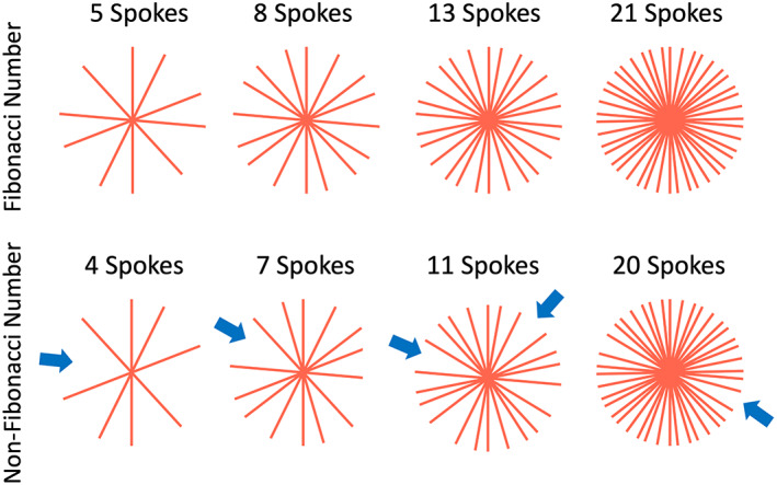
When the number of golden‐angle radial spokes equals one of the Fibonacci numbers, the acquired k‐space has a uniform coverage. When the number equals a non‐Fibonacci number, radial k‐space is less uniform with larger gaps (blue arrows).
FIGURE 6.
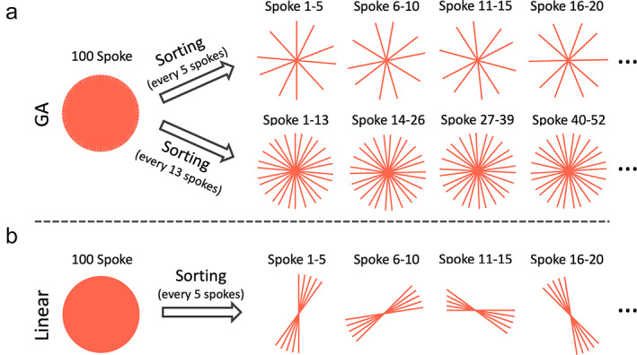
(a) Golden‐angle radial k‐space can be sorted into dynamic frames with flexible temporal resolution by grouping a different number of consecutive spokes together. When the number equals one of the Fibonacci numbers (e.g. 5 or 13), uniform k‐space coverage for each time point can be obtained. (b) For comparison, standard linear radial k‐space cannot be sorted into dynamic frames with a good coverage of k‐space.
SELF‐NAVIGATION
Self‐navigated radial MRI has become an active research topic in recent years. Here, self‐navigation refers to the ability to extract a motion signal (e.g. a respiratory motion or a cardiac motion signal) from the acquired data, so that the motion information can guide motion compensation or data sorting in image reconstruction to reduce motion artifacts. In radial sampling, the fact that the center of k‐space is repeatedly sampled by each radial spoke and each of them carries an equal amount of information provides the feasibility to extract a motion signal from the k‐space center. 21 , 22 , 23 , 24 , 25 , 26 , 27 This is because the center of k‐space corresponds to the DC component in the Fourier domain, and the overall signal variation in the entire FOV, often caused by motion, can thus be reflected by the DC components. When 3D radial sampling is performed (see below), the performance of self‐navigation can be further improved with a central k‐space line instead of only one data point.
With golden‐angle radial sampling, the extracted motion signal can be used to guide data sorting to generate a respiratory motion‐resolved image series, as shown in Fig. 7a. Golden‐angle radial rotation ensures a good k‐space coverage after motion‐resolved data sorting, 22 , 28 , 29 , 30 which could be problematic with standard linear rotation (Fig. 7b). XD‐GRASP (eXtra‐Dimensional Golden‐angle RAdial Sparse Parallel) MRI 22 is a representative technique that exploits this feature for free‐breathing MRI applications. After motion‐guided data sorting, a dynamic multicoil compressed sensing reconstruction can be performed to remove undersampling‐induced streaking artifacts to generate a motion‐resolved image series (see Supporting Information Fig. S2 for one example).
FIGURE 7.
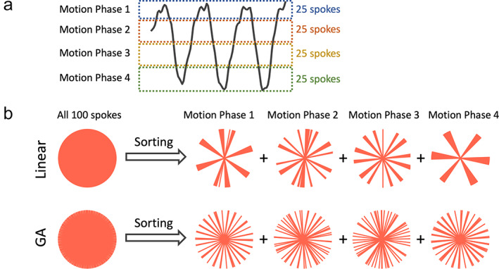
(a) Radial sampling offers self‐navigation with which a motion signal (e.g. a respiratory signal) can be extracted from the center of the acquired radial k‐space. The motion signal can guide sorting of golden‐angle radial k‐space, so that a motion‐resolved image series can be generated. (b) Golden‐angle radial sampling ensures a good coverage of k‐space for each motion phase after data sorting, while standard linear sampling does not provide this feature.
Limitations of Golden Angle Radial Sampling
Despite the advantages described above, golden‐angle radial sampling also has several important limitations. These include reduced scan efficiency, prolonged reconstruction time, contrast mixing, reduced performance in fat suppression, sensitivity to off‐resonance, gradient delay and eddy current, and strong streaking artifacts that can often be generated.
REDUCED IMAGING EFFICIENCY
Standard radial sampling has reduced imaging efficiency compared to Cartesian sampling with the same image matrix size. This is mainly because of the variable‐density sampling pattern in the radial trajectory and the repeatedly sampled k‐space center in radial imaging. To satisfy the Nyquist sampling rate, radial imaging typically requires more than M spokes to acquire an M × M image matrix, while Cartesian sampling only needs M k‐space lines. As a result, the sampling efficiency of radial imaging could be considerably lower than Cartesian sampling in general. Given this limitation, radial sampling is rarely used alone today, and it is commonly implemented in combination with advanced fast imaging techniques (e.g. compressed sensing or deep learning reconstruction), so that fully sampling of radial k‐space is not necessary.
PROLONGED RECONSTRUCTION TIME
In standard Cartesian sampling, k‐space data are sampled with an equal space along each spatial dimension, which allows for image reconstruction with a simple FFT when the Nyquist sampling rate is satisfied. Radial sampling, in contrast, leads to unequally spaced k‐space data, which prevents direct FFT reconstruction. Reconstructing radial k‐space data typically involves a process called gridding before FFT, in which radial data are interpolated onto a Cartesian grid. The interpolation can be performed with a predefined kernel, with which each radial sample is smeared to neighbor Cartesian locations based on their distance and corresponding weight defined in the kernel. This entire reconstruction process is also referred to as nonuniform FFT (NUFFT), 31 since it aims to reconstruct an image from unequally spaced (thus nonuniform) k‐space data. The need for gridding in radial image reconstruction inevitably prolongs overall reconstruction time, particularly in iterative reconstruction. Thus, development of more efficient NUFFT algorithms (e.g. gpuNUFFT 32 or TRON 33 ) or alternative algorithms (e.g. the GROG method 34 , 35 ) has been an important research direction now.
CONTRAST MIXING
An important feature of Cartesian sampling is the feasibility to produce different types of contrast by manipulating k‐space sampling ordering scheme. For example, Cartesian k‐space can be sampled with a linear ordering scheme (line‐by‐line from one k‐space edge to the other side) or a centric ordering scheme (from the center of k‐space to the periphery), which can result in different types of contrast weighting in some sequences such as fast spin echo (FSE). This, however, is challenging in radial sampling given the fact that all k‐space measurements pass through the center of k‐space and carry an equal amount of information. As a result, radial image typically has an averaged (or mixed) contrast from all k‐space spokes. This is generally not a problem for steady‐state acquisition (e.g. gradient echo) since the contrast is the same for all k‐space measurements once a steady state is achieved. However, it can be problematic in other sequences such as FSE or magnetization‐prepared imaging.
REDUCED FAT‐SUPPRESSION PERFORMANCE
Fat suppression in MRI typically starts with a fat‐suppression preparation module, which suppresses MRI signal from fat tissue. While the fat signal is recovering over time afterwards, a number of k‐space lines can be collected. In Cartesian sampling, one can specifically arrange k‐space sampling so that the k‐space center is sampled when the fat signal is fully nulled following the fat‐suppression preparation. Although some k‐space lines will always be sampled with fat signal, these measurements can be deliberately acquired in the outer k‐space region, thus resulting in reduced influence in image contrast. In standard radial imaging, however, the performance of fat suppression can be reduced due to the repeated sampling of k‐space center. As a result, all k‐space measurements with and without fat signal will have an equal contribution to the final image. This prevents good fat suppression in standard radial MRI and requires more advanced suppression strategies.
SENSITIVITY TO OFF‐RESONANCE
The sensitivity to off‐resonance is a challenge for non‐Cartesian imaging in general. In MRI, off‐resonance mainly comes from field inhomogeneity, susceptibility in air‐tissue boundaries and chemical shift effect from fat tissue, all of which can lead to additional phase accumulation along the readout direction. Such a phase modulation in the Fourier domain then results in a shift of the reconstructed image in image domain. This is generally not a big problem in standard Cartesian sampling, given its short repetition time (TR)/readout duration, good performance in fat suppression and a consistent phase‐encoding direction that results in a shift of the whole image toward one direction. However, radial sampling has a varying phase‐encoding direction, which, in the presence of off‐resonance, can lead to a shift of the reconstructed image along different directions to produce blurring. The reduced performance in fat suppression, as discussed above, can result in increased chemical‐shift effect to further exacerbate this problem. Fortunately, the readout duration in radial sampling is typically low, particularly when a high receiver bandwidth is applied. This ensures minimum phase accumulation due to off‐resonance in radial imaging. However, the off‐resonance‐induced image blurring could still be a severe problem in organs with an elevated amount of fat, such as the breast or the liver.
SENSITIVITY TO GRADIENT DELAY
Inaccuracies of gradient timing in MRI often lead to deviation of actually sampled k‐space locations from the theoretical sampling positions, which is known as the gradient delay effect. This is mainaly caused by eddy current during fast and strong gradient switching as well as other system imperfections such as gradient nonlinearity. Gradient delay can lead to a shift of k‐space samples along the readout direction, which then results in a phase modulation in image domain. Again, this is usually not a problem in standard Cartesian imaging, because it has a fixed readout direction and magnitude images is usually used in clinical exams. In radial sampling, however, this can be problematic because of its varying readout direction. Gradient delay in radial MRI (and non‐Cartesian MRI in general) can lead to varying phase modulation in image domain to cause signal inhomogeneity and/or blurring. Therefore, it is important to correct for this error in radial MRI acquisition and/or reconstruction using appropriate methods, such as that described by Block and Uecker . 36
STRONG STREAKING ARTIFACTS
Radial images can often be contaminated by strong streaking artifacts, as show in Fig. 8a for an example. Those streaks typically have much higher signal intensity than regular undersampling‐induced streaks. The artifacts usually come from regions with high‐signal spots and concentration that are caused by residual fat signal and/or image distortion due to gradient nonlinearity and off‐resonance in outer FOV. 37 , 38 , 39 Although those signal spots are usually far from image center, the resulting streaks can affect the entire images if not properly addressed. In contrast, this is typically not a problem in Cartesian sampling. Although Cartesian sampling also suffers from gradient nonlinearity and high signal concentration and distortion can also be generated, they usually occur in the peripheral FOV that can be easily cropped without affecting main image content, as shown in Fig. 8a. An easy way to address those strong streaks in radial imaging is to remove or attenuate the coil elements containing high‐intensity signal spots, so that they do not contribute or make less contribution to the final reconstructed images. 39 , 40 , 41 One example of this method, called unstreaking, is described in the literature. 40 , 42 A representative comparison of images reconstructed with and without unstreaking is shown in Fig. S3 of the Supplementary Material.
FIGURE 8.
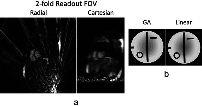
(a) Radial sampling is prone to strong streaking artifacts. These artifacts typically arise from high signal spots (e.g. caused by fat signal or signal concentration due to gradient nonlinearity and off‐resonance) in outer FOV. Artifacts generated from bright signal spots can also be found in Cartesian sampling, but they can be easily cropped. (b) Standard golden‐angle radial sampling is sensitive to eddy current due to the need of fast and large gradient switching in golden‐angle rotation. For comparison, radial sampling with linear rotation is more robust towards eddy current.
SENSITIVITY TO EDDY CURRENT
In standard golden‐angle radial MRI, fast and large gradient switching is usually needed because each spoke needs to rotate by a large angle from the previous one. This, unfortunately, can easily produce strong eddy current and related image artifacts compared to standard linear rotation, as shown in Fig. 8b. The tiny golden‐angle rotation scheme, 43 as will be seen in the next section, represents a promising approach to address this challenge.
Advanced Golden‐Angle Radial Sampling
Tiny Golden Angle Radial Sampling
Tiny golden angle rotation 43 is a novel extension of standard golden‐angle rotation to address its sensitivity to eddy current, and a number of prior studies have demonstrated its greater performance compared to standard golden‐angle radial sampling for 2D imaging applications. 44 , 45 , 46 , 47 A tiny golden angle can be calculated as follows:
| (6) |
From Eq. 6, we can obtain different golden angles depending on the parameter , the angles are called tiny golden angles when N > 2. When N = 1, Eq. 6 becomes Eq. 4 to calculate the standard golden angle. Figure 9a compares standard golden‐angle radial sampling with tiny golden‐angle radial sampling with N = 5. With tiny golden‐angle radial sampling, every consecutive spokes (but not a number less than ) lead to a good coverage of k‐space, as shown in Fig. 9b. Of course, every 2N or 3N spokes can also be combined to form an image. A large value of can help minimize eddy current better, but it provides uniform k‐space coverage less frequently.
FIGURE 9.
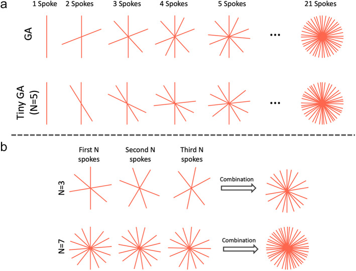
(a) Tiny golden angle radial sampling enables smaller rotation of spokes and thus reduces sensitivity to eddy current. There are different tiny golden angles depending the parameter as shown in Eq. 6. (b) For tiny golden‐angle radial sampling, dynamic images with uniform k‐space coverage can be obtained by grouping every or more consecutive spokes together.
Stack‐of‐Stars Golden‐Angle Radial Sampling
The stack‐of‐stars trajectory is an innovative sampling scheme that has seen increasing research and clinical use in recent years. 10 It is a 3D hybrid Cartesian‐radial trajectory that can overcome several limitations in 2D golden‐angle radial sampling. In the stack‐of‐stars trajectory, radial sampling is employed in the kx‐ky plane and Cartesian sampling is implemented along the kz dimension. The tiny golden‐angle rotation described above can also be implemented for the stack‐of‐stars trajectory.
GENERAL ADVANTAGES OF STACK‐OF‐STARS GOLDEN‐ANGLE RADIAL SAMPLING
Stack‐of‐stars sampling offers several unique advantages. First, the stack‐of‐stars trajectory allows for flexible selection of image resolution and FOV along the kz dimension, which can be different from that in the kx‐ky plane. Second, when the kz dimension is fully sampled in stack‐of‐stars imaging without changing the rotation angle, all slices (sampled on a Cartesian grid) can be detangled with FFT, so that image reconstruction can be performed slice by slice (without consuming too much memory) or can be parallelized to process more than one slice simultaneously. Third, partial Fourier, which is widely implemented in clinical Cartesian MRI, can also be implemented in the kz dimension in stack‐of‐stars sampling. This sampling trajectory also offers a few more important advantages, but it requires a specific acquisition scheme that will be discussed in the following subsection.
ACQUISITION ORDERING IN STACK‐OF‐STARS GOLDEN‐ANGLE RADIAL SAMPLING
The standard stack‐of‐stars trajectory can be implemented based on a partition‐in‐line (P‐in‐L) ordering scheme or a line‐in‐partition (L‐in‐P) ordering scheme, as shown in Fig. 10a. With P‐in‐L ordering, all spokes corresponding to different kz locations are first sampled on a Cartesian grid (referred to as a stack) for a given rotation angle before moving to the next angle (top row, Fig. 10a), and the same rotation angle is usually implemented for the entire stack. The sampling of each stack can be performed based on a linear (from one side to the other side) or a centric scheme (from the center to the two sides), as shown in Fig. 10b. With L‐in‐P ordering (bottom row, Fig. 10a), all radial spokes corresponding to one kz location are first acquired following golden‐angle rotation before moving to the next kz location. Although the overall trajectory is the same in the end, these two ordering schemes result in completely different imaging performance, as described below.
FIGURE 10.
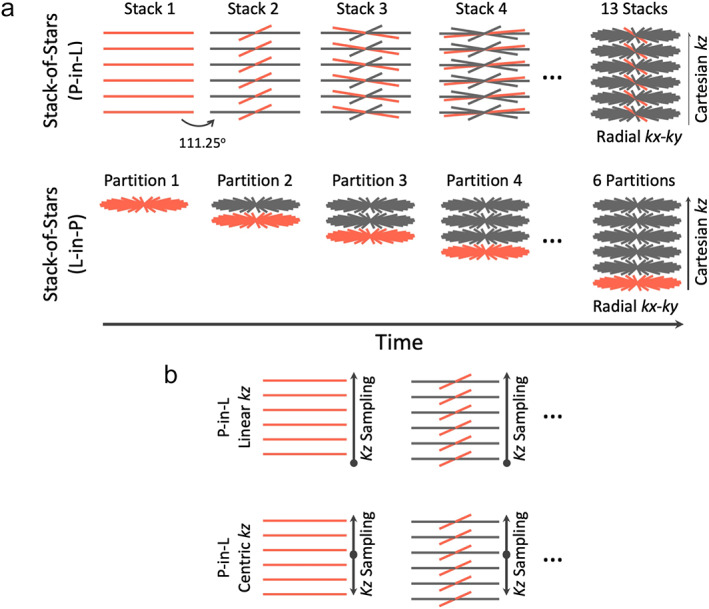
(a) Stack‐of‐stars golden‐angle radial sampling can be performed with a partition‐in‐line (P‐in‐L) ordering scheme or a line‐in‐partition (L‐in‐P) ordering scheme. For the P‐in‐L ordering scheme, all spokes from different kz locations (a radial stack) are sampled first before moving to the next stack. For the L‐in‐P ordering scheme, all radial spokes from a given kz location are acquired first before moving to the next kz location. (b) Stack‐of‐stars golden‐angle radial sampling allows for linear kz sampling or centric kz sampling when the P‐in‐L ordering scheme is used.
ADVANTAGES OF STACK‐OF‐STARS GOLDEN‐ANGLE RADIAL SAMPLING WITH P‐IN‐L ORDERING
In practice, the P‐in‐L ordering scheme is used more often in stack‐of‐stars imaging, because it can inherit the advantages of Cartesian sampling to achieve good fat suppression and avoid contrast mix while maintaining the motion robustness, incoherent undersampling and other advantages from radial sampling.
First, for fat suppression in stack‐of‐stars sampling with P‐in‐L ordering, a fat‐suppression module can be applied before the acquisition of each radial stack. Thus, k‐space data after each fat preparation are acquired on a Cartesian grid, which ensures good fat suppression.
Second, different types of contrast can be available in stack‐of‐stars sampling with P‐in‐L ordering. For example, the FSE sequence can be implemented using the stack‐of‐stars trajectory with P‐in‐L ordering, in which one radial stack (on a Cartesian grid) is acquired during one echo train (the echo train length equals the number of slices), so that different types of contrast offered by the FSE sequence can be maintained. 48 , 49
Third, stack‐of‐stars sampling with P‐in‐L ordering can be more robust to eddy current. It can be seen from Fig. 11 that stack‐of‐stars sampling with P‐in‐L ordering does not produce eddy current artifacts regardless of rotation schemes, while the L‐in‐P ordering scheme is more prone to eddy current artifacts. This is because acquisition of each radial stack only involves changing the kz gradient for P‐in‐L ordering. While the kx‐ky gradients also change substantially from the end of one stack to the beginning of the next one, the edge of k‐space is usually sampled first during the gradient switching period with linear kz ordering (Fig. 10b), which leads to minimum influence in image content. It is true that the central k‐space line needs to be acquired first right after the gradient jump for a centric kz ordering (Fig. 10b), but eddy current is not observed (Fig. 11), mainly because of the less frequent change of the kx‐ky gradients compared to 2D or L‐in‐P stack‐of‐stars golden‐angle radial sampling. Meanwhile, and perhaps more importantly, the fat preparation module, which is often implemented before the acquisition of each stack, inserts a nature gap between different radial stacks, which also helps reduce eddy current.
FIGURE 11.

Tiny golden‐angle rotation can be implemented in stack‐of‐stars golden‐angle radial sampling. However, although it is helpful with the L‐in‐P ordering scheme, it is not necessary for the P‐in‐L ordering scheme. In general, the P‐in‐L ordering scheme is more robust to eddy current artifacts in stack‐of‐stars golden‐angle radial imaging.
Lastly, it should also be realized that some applications, such as dynamic contrast‐enhanced MRI (DCE‐MRI), can only be performed with P‐in‐L ordering due to the need to capture contrast enhancement that occurs in real time.
SELF‐NAVIGATION IN STACK‐OF‐STARS GOLDEN‐ANGLE RADIAL IMAGING
Stack‐of‐stars golden‐angle radial sampling, when performed with P‐in‐L ordering, enable intrinsic self‐navigation that can be used for motion management. 22 , 27 As shown in Fig. 12a, the centers of k‐space in all the spokes in each radial stack form a central k‐space line (blur vertical line) that can be used for self‐navigation. After a z‐directional FFT, self‐navigation projections can be generated to reflect motion information, so that a motion signal (red curve) can be extracted from projections based on principal component analysis (PCA), 22 , 50 as shown in Fig. 12a. This motion signal can then be used to guide motion correction, motion sorting or motion‐resolved image reconstruction. Although self‐navigation has been demonstrated for different imaging orientations in stack‐of‐stars imaging, the performance is expected to be the best for axial imaging where self‐navigation projections are aligned along the H‐F direction (the dominant respiratory dimension). Self‐navigation can be very robust in steady‐state imaging, or when the underlying signal change is slow and smooth such as in DCE‐MRI. 22 However, when signal has substantial and quick changes (e.g. due to magnetization preparation), detection of a respiratory motion signal can be more challenging, and an external sensor, such as a respiratory bellow 51 or the new pilot tone technique, 52 could be more reliable. It should also be noted that this self‐navigation scheme would only be compatible with the P‐in‐L ordering scheme in stack‐of‐stars golden‐angle radial sampling. This will ensure that all the spokes in each radial stack are acquired during a similar motion state, so that a motion signal can be detected and retrospective data sorting is feasible.
FIGURE 12.
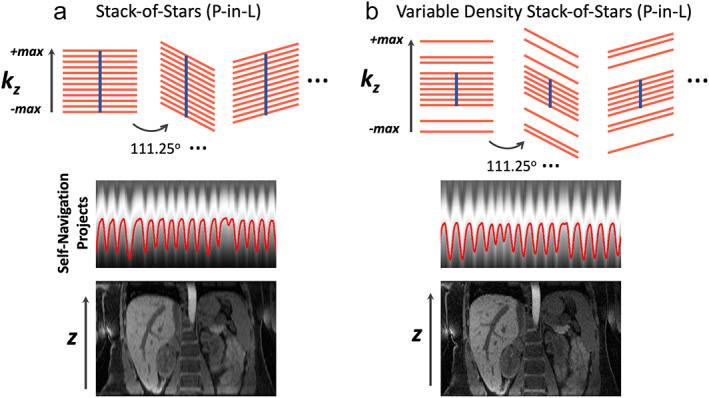
(a) Stack‐of‐stars golden‐angle radial sampling offers self‐navigation for motion detection. The centers of k‐space spokes in each stack can be used to generate z‐directional projection profiles, which contain motion information. This motion signal can be used for motion management, including motion sorting and correction in image reconstruction. (b) Additional acceleration can be performed along the kz dimension in stack‐of‐stars golden‐angle radial sampling. This so‐called kz‐accelerated variable‐density stack‐of‐stars sampling enables increased slice resolution or volumetric coverage without increasing scan time. When a central k‐space region is fully sampled, kz‐accelerated variable‐density stack‐of‐stars sampling also allows for self‐navigation.
ADDITIONAL VARIANTS OF STACK‐OF‐STARS GOLDEN‐ANGLE RADIAL SAMPLING
Different variants of stack‐of‐stars golden‐angle radial sampling have been proposed to improve imaging performance. One of them that may be clinically useful is called kz‐accelerated variable‐density stack‐of‐stars sampling, 53 which performs additional acceleration along the kz dimension that is fully sampled in the original stack‐of‐stars trajectory, as shown in Fig. 12b. With additional kz acceleration, imaging with higher slice resolution or higher volumetric coverage can be achieved without increasing scan time. In addition, a central k‐space region can be full sampled, while acceleration is only performed in the outer k‐space. This allows for self‐navigation while achieving higher slice resolution. The kz‐accelerated variable‐density stack‐of‐stars trajectory may ensure better imaging performance for applications that require high slice resolution or large volumetric coverage.
Stack‐of‐stars golden‐angle radial sampling can also be implemented with varying rotation angle along the kz‐dimension, which could potentially increase incoherence along the slice direction and thus reconstruction quality. 54 However, this trajectory may introduce eddy current artifacts if the rotation angle along kz is not properly selected.
The main disadvantage of these variants is the need to reconstruct all slices together, which cannot be separated in advance for parallelized processing. This leads to increased memory need and higher reconstruction burden.
3D Kooshball Golden‐Angle Radial Sampling
Radial sampling can also be implemented based on a kooshball pattern for 3D acquisition, and the rotation of each radial spoke, or a series of radial spokes (referred to as an interleaf), can be designed to follow golden‐angle rotation. For simplicity, this is referred to as 3D golden‐angle radial sampling hereafter. In 3D radial sampling, each spoke passes through the center of k‐space in the 3D space, and an image with an isotropic FOV and isotropic spatial resolution are typically generated. As a result, this sampling scheme is well‐suited for applications where retrospective image reformation is needed, such as whole‐heart MRI 24 , 29 , 50 , 55 or 3D MR angiography. 56 , 57 , 58 3D golden‐angle radial sampling can also be implemented for ultrashort echo time (UTE) imaging, with which each spoke starts from the center of k‐space to ensure UTE. 30 , 59 , 60 , 61 , 62 However, since only a half spoke is acquired in each repetition time (TR), it reduces overall sampling efficiency. There are two well‐accepted 3D golden‐angle radial sampling trajectories, one called 3D golden‐means radial sampling and one called 3D spiral phyllotaxis golden‐angle radial sampling.
3D GOLDEN‐MEANS RADIAL SAMPLING
As described in the first section, the golden mean (φ) in a 1D space, called the 1D golden mean, is defined as the inverse of the GR (1/GR ≈ 0.618). The golden mean can also be extended to a multidimensional space, and the 2D golden means are given as and . 4 From the first section, it has been shown that designing 2D golden‐angle radial sampling is based on cutting a line by the GR (or 1D golden mean). Similarly, one can also treat 3D golden‐angle radial sampling as cutting a 2D plane based on the 2D golden means, as shown by Chan et al. 4 The 3D golden‐means radial trajectory can be generated by calculating the azimuthal angle and the polar angle for each radial spoke, which are given as,
| (7) |
Here, m is the mth spoke to be acquired, is the azimuthal angle, and is the polar angle. Figure 13a shows a 3D golden‐means radial trajectory with a total of 160 spokes. Viewing from the top, it can be seen that the starting points of all radial spokes are sampled in a 2D plane, and each starting point is rotated based on the 2D golden means from the previous one. Similar to 2D golden‐angle radial sampling, 3D golden‐means radial data can also be sorted to generate a dynamic image series with flexible temporal resolution, where each temporal frame is a 3D volume with isotropic FOV and spatial resolution.
FIGURE 13.
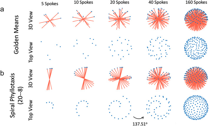
Two different 3D kooshball golden‐angle radial sampling trajectories, including 3D golden‐means radial sampling (a) and 3D spiral phyllotaxis golden‐angle radial sampling. In 3D golden‐means radial sampling, each spoke rotates by 2D golden means in two spatial dimensions from the previous spoke. In 3D spiral phyllotaxis golden‐angle radial sampling, all spokes are segmented into different interleaves, where each interleaf, consisting of a series of radial spokes, rotates by a golden angle (~137.51°) from the previous interleaf.
3D SPIRAL PHYLLOTAXIS GOLDEN‐ANGLE RADIAL SAMPLING
In 3D spiral phyllotaxis golden‐angle radial sampling, all the radial spokes are segmented into different interleaves, and each interleaf rotates by a golden angle from the previous one. This sampling trajectory, first proposed by Piccini et al, 63 follows the phyllotaxis pattern in as seen in botany, and each interleaf looks like a spiral arm, as shown in Fig. 13b. It should be noted that this is not a spiral trajectory that is commonly seen in the MRI field, and it is still a radial trajectory.
Similar to the 3D golden‐means trajectory, the 3D spiral phyllotaxis golden‐angle radial trajectory can also be generated by calculating the azimuthal and polar angles for each spoke.
| (8) |
Equation 8 indicates that two parameters, and , are associated with 3D spiral phyllotaxis golden‐angle radial sampling and need to be defined in advance. The first one is the number of radial spokes in each interleaf, and the second one is the total number of interleaves. The multiplication of and () then gives the total number of spokes to be acquired with this trajectory. For example, the trajectory shown in Fig. 13b follows a 20‐8 ( S = 20 and I = 8) pattern, where each interleaf has 20 spokes and there are a total of eight interleaves leading to a total of 160 spokes. The first 20 spokes are first sequentially sampled to constitute the first interleaf, followed by the second interleaf (the next 20 spokes) rotated by a golden angle ( in Eq. 8) from the first interleaf. The following interleaves are then acquired with the same pattern until all spokes are acquired. The golden angle of 137.51° is used in the 3D spiral phyllotaxis trajectory because each interleaf, viewing from the top, starts from the center and the entire 360° circle needs to be sampled to cover the whole k‐space.
Figure 14 shows two specific schemes of 3D spiral phyllotaxis golden‐angle radial sampling, one based on a 32–377 pattern (S = 32 and I = 377) and the other one based on a 32–385 pattern (S = 32 and I = 385). It can be seen that the overall trajectory is very sensitive to these two parameters. While the 32–377 pattern can guarantees smooth gradient changes to minimize eddy current, it does not give a uniform k‐space coverage until all the spokes are acquired. In contrast, the 32–385 pattern ensures nice k‐space coverage along time, despite a larger jump between spokes. In practice, one should always check the resulting trajectory based on the two parameters selected in advance. In general, the top pattern in Fig. 14 might be good for static MRI applications, such as coronary MRI, 64 , 65 while the bottom pattern might be better suited for dynamic MRI applications. 29 , 55 , 66
FIGURE 14.
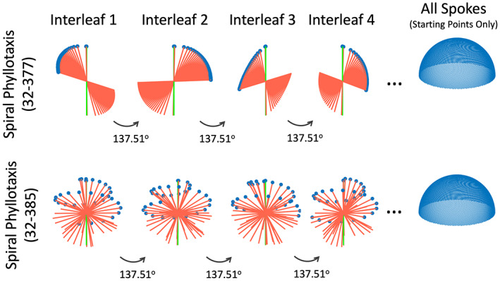
Two parameters need to be selected in the 3D spiral phyllotaxis golden‐angle radial trajectory, and it gives completely different sampling patterns. A self‐navigation spoke consistently oriented along the head‐to‐foot direction can be added to the beginning of each interleaf for motion detection.
SELF‐NAVIGATION IN 3D GOLDEN‐ANGLE RADIAL IMAGING
The default 3D golden‐angle radial trajectory, either implemented with 2D golden means rotation or spiral phyllotaxis rotation, does not provide self‐navigation. However, additional modification can be easily made to enable this feature. 24 , 50 Specifically, a radial spoke that is consistently aligned along the H‐F direction can be periodically inserted into 3D golden‐angle radial imaging, so that they can serve as self‐navigation spokes for motion detection. For 3D spiral phyllotaxis golden‐angle radial sampling, a self‐navigation spoke can be inserted in the beginning of each interleaf as a navigator, 64 as indicated by the green lines in Fig. 14.
Golden‐Angle Radial Sampling: Recommendations and Applications
This section first provides general recommendations to use different types of golden‐angle radial sampling trajectories. This is followed by brief discussion of their respective clinical applications. It should be noted that these recommendations are only for reference purpose. Interested readers should always consider their specific studies carefully when taking any of these suggestions.
General Recommendations
IMAGING ORIENTATION AND STREAKING ARTIFACTS REDUCTION
Radial sampling, particularly 2D golden‐angle radial sampling and 3D stack‐of‐stars golden‐angle sampling, tends to produce strong streaking artifacts due to bright signal spots and distortion‐induced signal concentration in outer FOV. This is more problematic when the size of the imaging target is big (e.g. coronal and sagittal body imaging or short‐axis cardiac imaging, as shown in Fig. 15). These streaks have strong signal intensity and are hard to remove even with advanced iterative image reconstruction. Meanwhile, when balanced steady‐state free precession (bSSFP) imaging is performed with radial sampling, the banding artifacts from outer FOV can further result in very strong streaking artifacts to degrade image quality.
FIGURE 15.
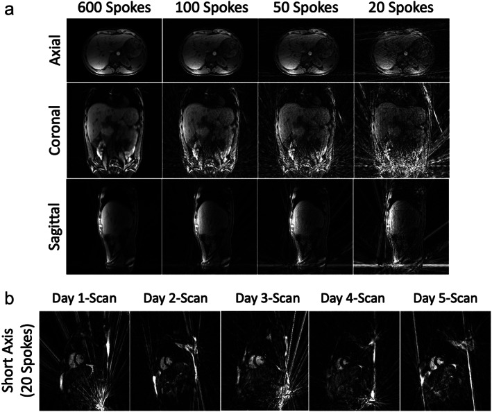
(a) 3D liver images acquired with stack‐of‐stars golden‐angle radial sampling at 3 T in different orientations. Coronal and sagittal undersampled images both show strong residual streaking artifacts from outer FOV, while axial undersampled images are more robust and acceptable. (b) Five cardiac cine images acquired using a 2D radial bSSFP sequence at 1.5 T from the same subject on five different days. All images show strong streaking artifacts in different regions that degrade image quality. These artifacts are generated from bright signal spots in outer FOV, mostly caused by signal concentration due to gradient nonlinearity and/or off‐resonance.
As a result, it is preferred to perform 2D golden‐angle and stack‐of‐stars golden‐angle radial sampling in the axial orientation, so that those artifacts can be largely avoided (Fig. 15a). Moreover, as shown in Figs. 4a and 15a, axial radial imaging ensures improved motion robustness compared to other imaging planes, and it also enables better self‐navigation as discussed in the previous section. However, it is expected that non‐axial imaging is still needed and important in specific applications, such as in cardiovascular MRI. For those applications, streaking artifact reduction 41 , 42 and additional motion compensation or correction will be essential.
For 3D golden‐angle radial sampling, this is less a concern because of its highly incoherent undersampling behavior, which helps spread the streaking artifacts to the entire 3D FOV with reduced signal intensity. Since 3D golden‐angle radial sampling provides isotropic spatial resolution and coverage, it is typically performed in the axial orientation.
GOLDEN‐ANGLE ROTATION, REORDERING, AND EDDY CURRENT
For 2D golden‐angle radial sampling, the tiny golden‐angle trajectory is strongly recommended to minimize eddy current artifacts. 44 Selection of a specific tiny golden‐angle rotation scheme (the parameter in Eq. 6) can be based on the desired temporal resolution in the target application.
For stack‐of‐stars golden‐angle radial sampling, it is also important to use tiny golden‐angle rotation to minimize eddy current artifacts when the acquisition is performed with the L‐in‐P ordering scheme, but this is not necessary for P‐in‐L ordering, as previously shown in Fig. 11. In general, the P‐in‐L ordering scheme is more recommended for stack‐of‐stars acquisition, since it inherits several important advantages from Cartesian sampling, including good performance in fat suppression and the flexibility to tailor image contrast in certain sequences such as FSE or magnetization‐prepared acquisition. In the meantime, some applications, such as DCE‐MRI, can only be performed with P‐in‐L ordering.
For 3D golden‐angle radial sampling, the performance of golden‐means rotation and spiral phyllotaxis rotation is expected to be comparable for dynamic MRI application. 29 , 50 The 3D spiral phyllotaxis golden‐angle radial trajectory provides additional flexibility in designing desired sampling trajectory, as shown in Fig. 14. Spokes can be acquired with small steps in each interleaf for static MRI (top row, Fig. 14), 65 while they can acquired more uniformly for dynamic MRI (bottom row, Fig. 14). 55
FAT SUPPRESSION
In general, the fat signal should be suppressed as much as possible in radial imaging if the fat information is not of interest. This can help minimize image blurring due to fat/water chemical shift. However, fat suppression still remains a main challenge for 2D golden‐angle and 3D golden‐angle sampling. Although water excitation can be applied, 50 , 67 it is sensitive to magnetic field inhomogeneity at high field, which may cause unwanted signal loss. A recently proposed method, called fast interrupted steady‐state (FISS), 68 , 69 holds great promise for improved fat suppression in radial imaging, but it is so far limited to steady‐state free precession imaging and the technique is not widely available yet. As a result, additional caution should be given when 2D golden‐angle and 3D golden‐angle sampling are implemented for applications where the elimination of fat signal is essential.
Fat suppression is less a problem in stack‐of‐stars golden‐angle radial sampling because of its hybrid radial‐Cartesian acquisition. Thus, it is particularly useful for 3D MRI applications where an isotropic spatial resolution is not necessary. Moreover, a relatively high receiver bandwidth can be used to help minimize image blurring due to residual fat signal.
SELF‐NAVIGATION AND MOTION DETECTION
Detection of respiratory motion has been shown to be very robust in different golden‐angle radial sampling schemes using k‐space centers 21 , 22 or additionally inserted self‐navigation k‐space data. 50 , 55 , 65 , 70 For stack‐of‐stars golden‐angle radial sampling, the P‐in‐L ordering should be used to enable this feature as discussed in the second section.
Detection of cardiac motion can be more challenging due to its higher frequency compared to respiratory motion. As a result, self‐navigation data need to be obtained frequently enough to capture the signal change due to cardiac beating. For 2D golden‐angle radial sampling, this is not a problem since a motion signal can be obtained from the center of each radial spoke. However, this could be more challenging in stack‐of‐stars golden‐angle and 3D golden‐angle radial imaging. In stack‐of‐stars golden‐angle sampling, a self‐navigation line can be available from each radial stack (Fig. 12). Thus, its performance of cardiac motion detection can be highly reduced when a large number of slices are acquired. For 3D golden‐angle radial sampling, self‐navigation spokes can be inserted more frequently (e.g. every 10 spokes) to capture cardiac motion at the cost of reduced overall sampling efficiency. New methods for cardiac motion detection are still desired for this purpose. A prior study has proposed to acquire a low‐resolution navigator in each TR for cardiac motion detection. 71 External sensors, such as the Pilot Tone device, would be very promising to address this challenge and can also be considered. 72
Clinical Applications
2D GOLDEN‐ANGLE RADIAL SAMPLING
2D golden‐angle radial sampling is well suited for fast real‐time dynamic MRI. For example, it has been demonstrated for real‐time imaging of joint movement, 73 cardiac function, 47 , 74 , 75 fetal heart, 45 , 76 , 77 speaking 78 and blood flow. 79 2D golden‐angle radial sampling has also been demonstrated for conventional ECG‐gated and segmented cardiac cine MRI. However, it has been shown that additional adaption of the golden‐angle rotation is needed to ensure more optimal k‐space coverage after data synchronization from multiple heart beats. 80 2D golden‐angle radial sampling is also suited for 2D MR parameter mapping, 81 , 82 which can be performed either with single‐shot acquisition or with multiple repetitions.
Since 2D radial sampling often produce strong streaking artifacts, 2D Cartesian sampling with 1D variable‐density undersampling is often used as an alternative. Indeed, 2D Cartesian sampling can be more robust toward various system imperfections and it has now been combined with compressed sensing for routine clinical use. 83 , 84 , 85 , 86 However, 2D Cartesian sampling only allows for 1D acceleration along the phase‐encoding direction, and without further modification, it does not allow for self‐navigation.
STACK‐OF‐STARS GOLDEN‐ANGLE RADIAL SAMPLING
Stack‐of‐stars golden‐angle radial sampling is most suited for 3D dynamic MRI applications where motion is a challenge. For example, it has been increasingly used for free‐breathing abdominal imaging, 12 , 48 , 49 cardiovascular imaging, 87 , 88 and DCE‐MRI. 10 , 16 , 89 , 90 , 91 In particular, the flexibility to provide varying temporal resolution with golden‐angle radial sampling can be exploited to reconstruct the same DCE‐MRI dataset for simultaneous qualitative assessment (with low temporal resolution) and quantitative perfusion analysis (with high temporal resolution). In addition, stack‐of‐stars golden‐angle radial sampling has also been demonstrated for imaging nonmoving organs in neuroimaging, 51 , 92 and it is also good for quantitative MRI, such as MR parameter mapping. 48 , 51 , 93 , 94
Stack‐of‐stars golden‐angle radial sampling is often compared against 3D golden‐angle Cartesian sampling, in which the phase‐encoding steps in the ky‐kz plane can be segmented into different interleaves rotated by the golden angle. 95 , 96 , 97 The main advantage of the 3D golden‐angle Cartesian trajectory is that all k‐space data are sampled directly on a Cartesian grid, so that the time‐consuming NUFFT is not needed for image reconstruction. Meanwhile, self‐navigation spokes can also be added to 3D golden‐angle Cartesian sampling for free‐breathing MRI applications. 95 , 96 , 98 A pilot study has previously shown that stack‐of‐stars golden‐angle radial sampling still gives better motion robustness, but it tends to generate more blurring compared to golden‐angle Cartesian sampling. 99 Currently, the selection of either sampling method is primarily based on user preference, and more studies to carefully compare the performance of these two golden‐angle sampling schemes are still needed.
3D KOOSHBALL GOLDEN‐ANGLE RADIAL SAMPLING
The use of 3D golden‐angle radial sampling in combination with advanced iterative reconstruction has also become very interesting in recent years. The main feature of 3D golden‐angle radial sampling includes its highly incoherent undersampling behavior and its intrinsic isotropic FOV and spatial resolution. On one hand, this is ideal for applications where retrospective image reformation is desired, such as whole‐heart imaging 29 , 50 , 55 , 64 or MR angiography (MRA). 56 , 57 It has also been applied for pulmonary MRI‐based UTE sampling with whole‐lung coverage. 30 , 59 , 60 , 61 , 62 On the other hand, the intrinsic isotropic FOV and spatial resolution in 3D golden‐angle radial sampling reduces overall sampling efficiency, since much more spokes are needed to satisfy the Nyquist rate compared to the 2D golden‐angle or stack‐of‐stars golden‐angle radial trajectories. As a result, for applications where an isotropic FOV and spatial resolution are not needed, 3D golden‐angle radial sampling is not necessary. For example, liver imaging typically requires a slice thickness that is larger than the in‐plane voxel size. For DCE‐MRI, an anisotropic FOV and spatial resolution may also preferable to increase imaging speed and signal‐to‐noise ratio (SNR). For those applications, stack‐of‐stars golden‐angle radial sampling might be better suited for 3D imaging.
Conclusion
Although radial sampling has a long history, it does not get wide clinical use because Cartesian images are much easier to acquire and reconstruct and Cartesian sampling is more robust to various system imperfections in MRI scanners. However, a major limitation of Cartesian sampling is its sensitivity to motion artifacts, and small motion can lead to visible blurring and/or ghosting artifacts. The overall performance of radial MRI has been greatly improved over the past decade with modern MRI scanners, and now it serves as a valuable alternative to Cartesian sampling when improved motion robustness is needed. Meanwhile, the introduction of golden‐angle rotation to radial MRI has been recognized as a major contribution to the field, as can be attested by the substantial attention and interest it has received in the MRI community. This article reviewed the basics of golden‐angle radial sampling, its advantages and limitations, and several advanced types of golden‐angle radial trajectories. Recommendations are also provided to use each of these trajectories along with their suitable clinical applications. It is with hope that this review paper can be useful both for clinicians who are interested in learning the potential benefits of golden‐angle radial sampling in day‐to‐day clinical exams and for MRI physicists who are interested in exploring this research direction.
Disclosure
Li Feng is a co‐inventor of two patents on the GRASP and XD‐GRASP imaging techniques for dynamic MRI.
Supporting information
Figure S1 Comparison of undersampled Cartesian images and radial images at different acceleration rates. Radial sampling enables acceleration along two spatial dimensions and shows higher incoherence than Cartesian sampling.
Figure S2 Golden‐angle radial sampling enables self‐navigation and motion‐guided data sorting to generate motion‐resolved images. A compressed sensing reconstruction can be performed to reduce resulting undersampling artifacts by exploiting temporal sparsity and incoherence presented in the new motion dimension. The yellow arrows indicate a region where motion‐resolved reconstruction improves image sharpness.
Figure S3 Radial sampling can produce strong residual streaking artifacts even after iterative sparse reconstruction. Methods to suppress these artifacts can be considered to improve image quality, which can be done by attenuating the contribution of coil elements that contain strong streaks.
Acknowledgment
This work was supported by the National Institute of Biomedical Imaging and Bioengineering (NIBIB): R01 EB030549, R01 EB031083 and R21 EB032917.
References
- 1. Lauterbur PC. Image formation by induced local interactions: Examples employing nuclear magnetic resonance. Nature 1973;242:190‐191. [PubMed] [Google Scholar]
- 2. Winkelmann S, Schaeffter T, Koehler T, Eggers H, Doessel O. An optimal radial profile order based on the golden ratio for time‐resolved MRI. IEEE Trans Med Imaging 2007;26:68‐76. [DOI] [PubMed] [Google Scholar]
- 3. Dunlap RA The Golden ratio and Fibonacci numbers. World Scientific, 1997.
- 4. Chan RW, Ramsay EA, Cunningham CH, Plewes DB. Temporal stability of adaptive 3D radial MRI using multidimensional golden means. Magn Reson Med 2009;61:354‐363. [DOI] [PubMed] [Google Scholar]
- 5. Robson MD, Gatehouse PD, Bydder M, Bydder GM. Magnetic resonance: An introduction to ultrashort TE (UTE) imaging. J Comput Assist Tomogr 2003;27:825‐846. [DOI] [PubMed] [Google Scholar]
- 6. Chandarana H, Block TK, Rosenkrantz AB, et al. Free‐breathing radial 3D fat‐suppressed T1‐weighted gradient echo sequence: A viable alternative for contrast‐enhanced liver imaging in patients unable to suspend respiration. Invest Radiol 2011;46:648‐653. [DOI] [PubMed] [Google Scholar]
- 7. Zaitsev M, Maclaren J, Herbst M. Motion artefacts in MRI: A complex problem with many partial solutions. J Magn Reson Imaging 2015;42:887‐901. [DOI] [PMC free article] [PubMed] [Google Scholar]
- 8. Glover GH, Pauly JM. Projection reconstruction techniques for reduction of motion effects in MRI. Magn Reson Med 1992;28:275‐289. [DOI] [PubMed] [Google Scholar]
- 9. Gai N, Axel L. Correction of motion artifacts in linogram and projection reconstruction MRI using geometry and consistency constraints. Med Phys 1996;23:251‐262. [DOI] [PubMed] [Google Scholar]
- 10. Block KT, Chandarana H, Milla S, et al. Towards routine clinical use of radial stack‐of‐stars 3D gradient‐Echo sequences for reducing motion sensitivity. J Korean Soc Magn Reson Med 2014;18:87‐106. [Google Scholar]
- 11. Chandarana H, Block KT, Winfeld MJ, et al. Free‐breathing contrast‐enhanced T1‐weighted gradient‐echo imaging with radial k‐space sampling for paediatric abdominopelvic MRI. Eur Radiol 2013;24:320‐326. [DOI] [PubMed] [Google Scholar]
- 12. Benkert T, Feng L, Sodickson DK, Chandarana H, Block KT. Free‐breathing volumetric fat/water separation by combining radial sampling, compressed sensing, and parallel imaging. Magn Reson Med 2017;78:565‐576. [DOI] [PMC free article] [PubMed] [Google Scholar]
- 13. Block KT, Uecker M, Frahm J. Undersampled radial MRI with multiple coils. Iterative image reconstruction using a total variation constraint. Magn Reson Med 2007;57:1086‐1098. [DOI] [PubMed] [Google Scholar]
- 14. Adluru G, McGann C, Speier P, Kholmovski EG, Shaaban A, Dibella EVR. Acquisition and reconstruction of undersampled radial data for myocardial perfusion magnetic resonance imaging. J Magn Reson Imaging 2009;29:466‐473. [DOI] [PMC free article] [PubMed] [Google Scholar]
- 15. Feng L, Grimm R, Block KT, et al. Golden‐angle radial sparse parallel MRI: Combination of compressed sensing, parallel imaging, and golden‐angle radial sampling for fast and flexible dynamic volumetric MRI. Magn Reson Med 2014;72:707‐717. [DOI] [PMC free article] [PubMed] [Google Scholar]
- 16. Feng L, Benkert T, Block KT, Sodickson DK, Otazo R, Chandarana H. Compressed sensing for body MRI. J Magn Reson Imaging 2017;45:966‐987. [DOI] [PMC free article] [PubMed] [Google Scholar]
- 17. Chan RW, Ramsay EA, Cheung EY, Plewes DB. The influence of radial undersampling schemes on compressed sensing reconstruction in breast MRI. Magn Reson Med 2012;67:363‐377. [DOI] [PubMed] [Google Scholar]
- 18. Feng L, Wen Q, Huang C, Tong A, Liu F, Chandarana H. GRASP‐pro: imProving GRASP DCE‐MRI through self‐calibrating subspace‐modeling and contrast phase automation. Magn Reson Med 2020;83:94‐108. [DOI] [PMC free article] [PubMed] [Google Scholar]
- 19. Lustig M, Donoho D, Pauly JM. Sparse MRI: The application of compressed sensing for rapid MR imaging. Magn Reson Med 2007;58:1182‐1195. [DOI] [PubMed] [Google Scholar]
- 20. Chandarana H, Feng L, Block TK, et al. Free‐breathing contrast‐enhanced multiphase MRI of the liver using a combination of compressed sensing, parallel imaging, and golden‐angle radial sampling. Invest Radiol 2013;48:10‐16. [DOI] [PMC free article] [PubMed] [Google Scholar]
- 21. Larson AC, White RD, Laub G, McVeigh ER, Li D, Simonetti OP. Self‐gated cardiac cine MRI. Magn Reson Med 2004;51:93‐102. [DOI] [PMC free article] [PubMed] [Google Scholar]
- 22. Feng L, Axel L, Chandarana H, Block KT, Sodickson DK, Otazo R. XD‐GRASP: Golden‐angle radial MRI with reconstruction of extra motion‐state dimensions using compressed sensing. Magn Reson Med 2016;75:775‐788. [DOI] [PMC free article] [PubMed] [Google Scholar]
- 23. Grimm R, Fürst S, Dregely I, et al. Self‐gated radial MRI for respiratory motion compensation on hybrid PET/MR systems. Med Image Comput Comput Assist Interv 2013;16(Pt 3):17‐24. [DOI] [PubMed] [Google Scholar]
- 24. Stehning C, Börnert P, Nehrke K, Eggers H, Stuber M. Free‐breathing whole‐heart coronary MRA with 3D radial SSFP and self‐navigated image reconstruction. Magn Reson Med 2005;54:476‐480. [DOI] [PubMed] [Google Scholar]
- 25. Larson AC, Kellman P, Arai A, et al. Preliminary investigation of respiratory self‐gating for free‐breathing segmented cine MRI. Magn Reson Med 2005;53:159‐168. [DOI] [PMC free article] [PubMed] [Google Scholar]
- 26. Lin W, Guo J, Rosen MA, Hee KS. Respiratory motion‐compensated radial dynamic contrast‐enhanced (DCE)‐MRI of chest and abdominal lesions. Magn Reson Med 2008;60:1135‐1146. [DOI] [PMC free article] [PubMed] [Google Scholar]
- 27. Liu J, Spincemaille P, Codella NCF, Nguyen TD, Prince MR, Wang Y. Respiratory and cardiac self‐gated free‐breathing cardiac CINE imaging with multiecho 3D hybrid radial SSFP acquisition. Magn Reson Med 2010;63:1230‐1237. [DOI] [PMC free article] [PubMed] [Google Scholar]
- 28. Chandarana H, Feng L, Ream J, et al. Respiratory motion‐resolved compressed sensing reconstruction of free‐breathing radial acquisition for dynamic liver magnetic resonance imaging. Invest Radiol 2015;50:749‐756. [DOI] [PMC free article] [PubMed] [Google Scholar]
- 29. Feng L, Coppo S, Piccini D, et al. 5D whole‐heart sparse MRI. Magn Reson Med 2018;79:826‐838. [DOI] [PMC free article] [PubMed] [Google Scholar]
- 30. Feng L, Delacoste J, Smith D, et al. Simultaneous evaluation of lung anatomy and ventilation using 4D respiratory‐motion‐resolved ultrashort echo time sparse MRI. J Magn Reson Imaging 2019;49:411‐422. [DOI] [PMC free article] [PubMed] [Google Scholar]
- 31. Fessler JA, Sutton BP. Nonuniform fast Fourier transforms using min‐max interpolation. IEEE Trans Signal Proces 2003;51:560‐574. [Google Scholar]
- 32. Knoll F, Schwarzl A, Diwoky C, Sodickson DK. gpuNUFFT ‐ an open source GPU library for 3D regridding with direct Matlab interface. Proceedings of the 22nd Annual Meeting of ISMRM. Milano, Italy; ISMRM; 2014. p 4297. [Google Scholar]
- 33. Smith DS, Sengupta S, Smith SA, Brian Welch E. Trajectory optimized NUFFT: Faster non‐Cartesian MRI reconstruction through prior knowledge and parallel architectures. Magn Reson Med 2019;81:2064‐2071. [DOI] [PMC free article] [PubMed] [Google Scholar]
- 34. Seiberlich N, Breuer F, Blaimer M, Jakob P, Griswold M. Self‐calibrating GRAPPA operator gridding for radial and spiral trajectories. Magn Reson Med 2008;59:930‐935. [DOI] [PubMed] [Google Scholar]
- 35. Benkert T, Tian Y, Huang C, DiBella EVR, Chandarana H, Feng L. Optimization and validation of accelerated golden‐angle radial sparse MRI reconstruction with self‐calibrating GRAPPA operator gridding. Magn Reson Med 2018;80:286‐293. [DOI] [PMC free article] [PubMed] [Google Scholar]
- 36. Block TK, Uecker M. Simple method for adaptive gradient‐delay compensation in radial MRI. Proceedings of the 19th Annual Meeting of ISMRM. Montreal, Canada: ISMRM; 2011. p 2816. [Google Scholar]
- 37. Langlois S, Desvignes M, Constans JM, Revenu M. MRI geometric distortion: A simple approach to correcting the effects of non‐linear gradient fields. J Magn Reson Imaging 1999;9:821‐831. [DOI] [PubMed] [Google Scholar]
- 38. Du J, Thornton FJ, Fain SB, et al. Artifact reduction in undersampled projection reconstruction MRI of the peripheral vessels using selective excitation. Magn Reson Med 2004;51:1071‐1076. [DOI] [PubMed] [Google Scholar]
- 39. Xue Y, Yu J, Kang HS, Englander S, Rosen MA, Song HK. Automatic coil selection for streak artifact reduction in radial MRI. Magn Reson Med 2012;67:470‐476. [DOI] [PubMed] [Google Scholar]
- 40. Feng L, Huang C, Shanbhogue K, Sodickson DK, Chandarana H, Otazo R. RACER‐GRASP: Respiratory‐weighted, aortic contrast enhancement‐guided and coil‐unstreaking golden‐angle radial sparse MRI. Magn Reson Med 2018;80:77‐89. [DOI] [PMC free article] [PubMed] [Google Scholar]
- 41. Mandava S, Keerthivasan MB, Martin DR, Altbach MI, Bilgin A. Radial streak artifact reduction using phased array beamforming. Magn Reson Med 2019;81:3915‐3923. [DOI] [PMC free article] [PubMed] [Google Scholar]
- 42. Feng L, Chandarana H, Sodickson DK, Otazo R. Unstreaking: Radial MRI with automatic streaking artifact reduction. Proceedings of the 25th Annual Meeting of ISMRM. Honolulu, HI, USA: ISMRM; 2017. p 4001. [Google Scholar]
- 43. Wundrak S, Paul J, Ulrici J, Hell E, Rasche V. A small surrogate for the golden angle in time‐resolved radial MRI based on generalized fibonacci sequences. IEEE Trans Med Imaging 2015;34:1262‐1269. [DOI] [PubMed] [Google Scholar]
- 44. Wundrak S, Paul J, Ulrici J, et al. Golden ratio sparse MRI using tiny golden angles. Magn Reson Med 2016;75:2372‐2378. [DOI] [PubMed] [Google Scholar]
- 45. Haris K, Hedström E, Bidhult S, et al. Self‐gated fetal cardiac MRI with tiny golden angle iGRASP: A feasibility study. J Magn Reson Imaging 2017;46:207‐217. [DOI] [PubMed] [Google Scholar]
- 46. Li H, Metze P, Abaei A, et al. Feasibility of real‐time cardiac MRI in mice using tiny golden angle radial sparse. NMR Biomed 2020;33:e4300. [DOI] [PubMed] [Google Scholar]
- 47. Haji‐Valizadeh H, Rahsepar AA, Collins JD, et al. Validation of highly accelerated real‐time cardiac cine MRI with radial k‐space sampling and compressed sensing in patients at 1.5T and 3T. Magn Reson Med 2018;79:2745‐2751. [DOI] [PMC free article] [PubMed] [Google Scholar]
- 48. Keerthivasan MB, Saranathan M, Johnson K, et al. An efficient 3D stack‐of‐stars turbo spin echo pulse sequence for simultaneous T2‐weighted imaging and T2 mapping. Magn Reson Med 2019;82:326‐341. [DOI] [PMC free article] [PubMed] [Google Scholar]
- 49. Benkert T, Mugler JP, Rigie DS, Sodickson DK, Chandarana H, Block KT. Hybrid T2‐ and T1‐weighted radial acquisition for free‐breathing abdominal examination. Magn Reson Med 2018;80:1935‐1948. [DOI] [PMC free article] [PubMed] [Google Scholar]
- 50. Pang J, Sharif B, Fan Z, et al. ECG and navigator‐free four‐dimensional whole‐heart coronary MRA for simultaneous visualization of cardiac anatomy and function. Magn Reson Med 2014;72:1208‐1217. [DOI] [PMC free article] [PubMed] [Google Scholar]
- 51. Feng L, Liu F, Soultanidis G, et al. Magnetization‐prepared GRASP MRI for rapid 3D T1 mapping and fat/water‐separated T1 mapping. Magn Reson Med 2021;86:97‐114. [DOI] [PMC free article] [PubMed] [Google Scholar]
- 52. Vahle T, Bacher M, Rigie D, et al. Respiratory motion detection and correction for MR using the pilot tone applications for MR and simultaneous PET/MR examinations. Invest Radiol 2020;55:153‐159. [DOI] [PMC free article] [PubMed] [Google Scholar]
- 53. Feng L, Zhao T, Chandarana H, Sodickson DK, Otazo R. Motion‐resolved golden‐angle radial sparse MRI using variable‐density stack‐of‐stars sampling. Proceedings of the 24th Annual Meeting of ISMRM. Singapore: ISMRM; 2016.1091. [Google Scholar]
- 54. Zhou Z, Han F, Yan L, Wang DJJ, Hu P. Golden‐ratio rotated stack‐of‐stars acquisition for improved volumetric MRI. Magn Reson Med 2017;78:2290‐2298. [DOI] [PMC free article] [PubMed] [Google Scholar]
- 55. Coppo S, Piccini D, Bonanno G, et al. Free‐running 4D whole‐heart self‐navigated golden angle MRI: Initial results. Magn Reson Med 2015;74:1306‐1316. [DOI] [PubMed] [Google Scholar]
- 56. Mistretta CA. Undersampled radial MR acquisition and highly constrained back projection (HYPR) reconstruction: Potential medical imaging applications in the post‐Nyquist era. J Magn Reson Imaging 2009;29:501‐516. [DOI] [PubMed] [Google Scholar]
- 57. Wu H, Block WF, Turski PA, Mistretta CA, Johnson KM. Noncontrast‐enhanced three‐dimensional (3D) intracranial MR angiography using pseudocontinuous arterial spin labeling and accelerated 3D radial acquisition. Magn Reson Med 2013;69:708‐715. [DOI] [PMC free article] [PubMed] [Google Scholar]
- 58. Grist TM, Mistretta CA, Strother CM, Turski PA. Time‐resolved angiography: Past, present, and future. J Magn Reson Imaging 2012;36:1273‐1286. [DOI] [PubMed] [Google Scholar]
- 59. Johnson KM, Fain SB, Schiebler ML, Nagle S. Optimized 3D ultrashort echo time pulmonary MRI. Magn Reson Med 2013;70:1241‐1250. [DOI] [PMC free article] [PubMed] [Google Scholar]
- 60. Jiang W, Ong F, Johnson KM, et al. Motion robust high resolution 3D free‐breathing pulmonary MRI using dynamic 3D image self‐navigator. Magn Reson Med 2018;79:2954‐2967. [DOI] [PMC free article] [PubMed] [Google Scholar]
- 61. Zhu X, Chan M, Lustig M, Johnson KM, Larson PEZ. Iterative motion‐compensation reconstruction ultra‐short TE (iMoCo UTE) for high‐resolution free‐breathing pulmonary MRI. Magn Reson Med 2020;83:1208‐1221. [DOI] [PMC free article] [PubMed] [Google Scholar]
- 62. Delacoste J, Chaptinel J, Beigelman‐Aubry C, Piccini D, Sauty A, Stuber M. A double echo ultra short echo time (UTE) acquisition for respiratory motion‐suppressed high resolution imaging of the lung. Magn Reson Med 2018;79:2297‐2305. [DOI] [PubMed] [Google Scholar]
- 63. Piccini D, Littmann A, Nielles‐Vallespin S, Zenge MO. Spiral phyllotaxis: The natural way to construct a 3D radial trajectory in MRI. Magn Reson Med 2011;66:1049‐1056. [DOI] [PubMed] [Google Scholar]
- 64. Piccini D, Littmann A, Nielles‐Vallespin S, Zenge MO. Respiratory self‐navigation for whole‐heart bright‐blood coronary MRI: Methods for robust isolation and automatic segmentation of the blood pool. Magn Reson Med 2012;68:571‐579. [DOI] [PubMed] [Google Scholar]
- 65. Piccini D, Monney P, Sierro C, et al. Respiratory self‐navigated postcontrast whole‐heart coronary MR angiography: Initial experience in patients. Radiology 2014;270:378‐386. [DOI] [PubMed] [Google Scholar]
- 66. Piccini D, Feng L, Bonanno G, et al. Four‐dimensional respiratory motion‐resolved whole heart coronary MR angiography. Magn Reson Med 2017;77:1473‐1484. [DOI] [PMC free article] [PubMed] [Google Scholar]
- 67. Masala N, Bastiaansen JAM, Di Sopra L, et al. Free‐running 5D coronary MR angiography at 1.5T using LIBRE water excitation pulses. Magn Reson Med 2020;84:1470‐1485. [DOI] [PubMed] [Google Scholar]
- 68. Koktzoglou I, Edelman RR. Radial fast interrupted steady‐state (FISS) magnetic resonance imaging. Magn Reson Med 2018;79:2077‐2086. [DOI] [PMC free article] [PubMed] [Google Scholar]
- 69. Bastiaansen JAM, Piccini D, Di Sopra L, et al. Natively fat‐suppressed 5D whole‐heart MRI with a radial free‐running fast‐interrupted steady‐state (FISS) sequence at 1.5T and 3T. Magn Reson Med 2020;83:45‐55. [DOI] [PMC free article] [PubMed] [Google Scholar]
- 70. Pang J, Bhat H, Sharif B, et al. Whole‐heart coronary MRA with 100% respiratory gating efficiency: Self‐navigated three‐dimensional retrospective image‐based motion correction (TRIM). Magn Reson Med 2014;71:67‐74. [DOI] [PMC free article] [PubMed] [Google Scholar]
- 71. Rigie D, Vahle T, Zhao T, et al. Cardiorespiratory motion‐tracking via self‐refocused rosette navigators. Magn Reson Med 2019;81:2947‐2958. [DOI] [PMC free article] [PubMed] [Google Scholar]
- 72. Falcão MBL, Di Sopra L, Ma L, et al. Pilot tone navigation for respiratory and cardiac motion‐resolved free‐running 5D flow MRI. Magn Reson Med 2022;87:718‐732. [DOI] [PMC free article] [PubMed] [Google Scholar]
- 73. Krohn S, Gersdorff N, Wassmann T, et al. Real‐time MRI of the temporomandibular joint at 15 frames per second—A feasibility study. Eur J Radiol 2016;85:2225‐2230. [DOI] [PubMed] [Google Scholar]
- 74. Zhang S, Joseph AA, Voit D, et al. Real‐time magnetic resonance imaging of cardiac function and flow‐recent progress. Quant Imaging Med Surg 2014;4:313‐329. [DOI] [PMC free article] [PubMed] [Google Scholar]
- 75. Wang X, Uecker M, Feng L. Fast real‐time cardiac MRI: A review of current techniques and future directions. Investig Magn Reson Imaging 2021;25:252‐265. [Google Scholar]
- 76. Roy CW, Seed M, Kingdom JC, Macgowan CK. Motion compensated cine CMR of the fetal heart using radial undersampling and compressed sensing. J Cardiovasc Magn Reson 2017;19:1‐14. [DOI] [PMC free article] [PubMed] [Google Scholar]
- 77. Chaptinel J, Yerly J, Mivelaz Y, et al. Fetal cardiac cine magnetic resonance imaging in utero. Sci Rep 2017;7:15540. [DOI] [PMC free article] [PubMed] [Google Scholar]
- 78. Niebergall A, Zhang S, Kunay E, et al. Real‐time MRI of speaking at a resolution of 33 ms: Undersampled radial FLASH with nonlinear inverse reconstruction. Magn Reson Med 2013;69:477‐485. [DOI] [PubMed] [Google Scholar]
- 79. Haji‐Valizadeh H, Feng L, Ma LE, et al. Highly accelerated, real‐time phase‐contrast MRI using radial k‐space sampling and GROG‐GRASP reconstruction: A feasibility study in pediatric patients with congenital heart disease. NMR Biomed 2020;33:e4240. [DOI] [PMC free article] [PubMed] [Google Scholar]
- 80. Han F, Zhou Z, Rapacchi S, Nguyen KL, Finn JP, Hu P. Segmented golden ratio radial reordering with variable temporal resolution for dynamic cardiac MRI. Magn Reson Med 2016;76:94‐103. [DOI] [PMC free article] [PubMed] [Google Scholar]
- 81. Wang X, Roeloffs V, Klosowski J, et al. Model‐based T1 mapping with sparsity constraints using single‐shot inversion‐recovery radial FLASH. Magn Reson Med 2018;79:730‐740. [DOI] [PubMed] [Google Scholar]
- 82. Ben‐Eliezer N, Sodickson DK, Shepherd T, Wiggins GC, Block KT. Accelerated and motion‐robust in vivo T2 mapping from radially undersampled data using Bloch‐simulation‐based iterative reconstruction. Magn Reson Med 2016;75:1346‐1354. [DOI] [PMC free article] [PubMed] [Google Scholar]
- 83. Sartoretti E, Sartoretti T, Binkert C, et al. Reduction of procedure times in routine clinical practice with compressed SENSE magnetic resonance imaging technique. PLoS One 2019;14:e0214887. [DOI] [PMC free article] [PubMed] [Google Scholar]
- 84. Ma Y, Hou Y, Ma Q, Wang X, Sui S, Wang B. Compressed SENSE single‐breath‐hold and free‐breathing cine imaging for accelerated clinical evaluation of the left ventricle. Clin Radiol 2019;74:325.e9‐325.e17. [DOI] [PubMed] [Google Scholar]
- 85. Allen BD, Carr M, Botelho MPF, et al. Highly accelerated cardiac MRI using iterative SENSE reconstruction: Initial clinical experience. Int J Cardiovasc Imaging 2016;32:955‐963. [DOI] [PubMed] [Google Scholar]
- 86. Vincenti G, Monney P, Chaptinel J, et al. Compressed sensing single‐breath‐hold CMR for fast quantification of LV function, volumes, and mass. JACC Cardiovasc Imaging 2014;7:882‐892. [DOI] [PubMed] [Google Scholar]
- 87. Haji‐Valizadeh H, Collins JD, Aouad PJ, et al. Accelerated, free‐breathing, non‐contrast, ECG‐triggered, thoracic MRA with stack‐of‐stars k‐space sampling and GRASP reconstruction. Magn Reson Med 2019;81:524‐532. [DOI] [PMC free article] [PubMed] [Google Scholar]
- 88. Zhang X, Xie G, Lu N, et al. 3D self‐gated cardiac cine imaging at 3 tesla using stack‐of‐stars bSSFP with tiny golden angles and compressed sensing. Magn Reson Med 2019;81:3234‐3244. [DOI] [PubMed] [Google Scholar]
- 89. Rosenkrantz AB, Geppert C, Grimm R, et al. Dynamic contrast‐enhanced MRI of the prostate with high spatiotemporal resolution using compressed sensing, parallel imaging, and continuous golden‐angle radial sampling: Preliminary experience. J Magn Reson Img 2015;41(5):1365‐1373. 10.1002/jmri.24661 [DOI] [PMC free article] [PubMed] [Google Scholar]
- 90. Kim SG, Feng L, Grimm R, et al. Influence of temporal regularization and radial undersampling factor on compressed sensing reconstruction in dynamic contrast enhanced MRI of the breast. J Magn Reson Img 2016;43(1):261‐269. 10.1002/jmri.24961 [DOI] [PMC free article] [PubMed] [Google Scholar]
- 91. Chen L, Liu D, Zhang J, et al. Free‐breathing dynamic contrast‐enhanced MRI for assessment of pulmonary lesions using golden‐angle radial sparse parallel imaging. J Magn Reson Img 2018;48(2):459‐468. 10.1002/jmri.25977 [DOI] [PMC free article] [PubMed] [Google Scholar]
- 92. Tomppert A, Wuest W, Wiesmueller M, et al. Achieving high spatial and temporal resolution with perfusion MRI in the head and neck region using golden‐angle radial sampling. Eur Radiol 2020;31:2263‐2271. [DOI] [PMC free article] [PubMed] [Google Scholar]
- 93. Li Z, Xu X, Yang Y, Feng L. Repeatability and robustness of MP‐GRASP T1 mapping. Magn Reson Med 2022;87:2271‐2286. [DOI] [PMC free article] [PubMed] [Google Scholar]
- 94. Wang N, Cao T, Han F, et al. Free‐breathing multitasking multi‐echo MRI for whole‐liver water‐specific T1 , proton density fat fraction, and [formula: See text] quantification. Magn Reson Med 2022;87:120‐137. [DOI] [PMC free article] [PubMed] [Google Scholar]
- 95. Prieto C, Doneva M, Usman M, et al. Highly efficient respiratory motion compensated free‐breathing coronary MRA using golden‐step Cartesian acquisition. J Magn Reson Imaging 2015;41:738‐746. [DOI] [PubMed] [Google Scholar]
- 96. Cheng JY, Zhang T, Ruangwattanapaisarn N, et al. Free‐breathing pediatric MRI with nonrigid motion correction and acceleration. J Magn Reson Imaging 2015;42:407‐420. [DOI] [PMC free article] [PubMed] [Google Scholar]
- 97. Zhu Y, Guo Y, Lingala SG, Lebel RM, Law M, Nayak KS. GOCART: GOlden‐angle CArtesian randomized time‐resolved 3D MRI. Magn Reson Imaging 2016;34:940‐950. [DOI] [PubMed] [Google Scholar]
- 98. Liu J, Feng L, Shen HW, et al. Highly‐accelerated self‐gated free‐breathing 3D cardiac cine MRI: Validation in assessment of left ventricular function. Magn Reson Mater Physics, Biol Med 2017;30:337‐346. [DOI] [PMC free article] [PubMed] [Google Scholar]
- 99. Feng L, Chandarana H, Zhao T, Bruno M, Sodickson DK, Otazo R. Golden‐angle sparse liver imaging: Radial or Cartesian sampling. Proceedings of the 25th Annual Meeting of ISMRM; Honolulu, HI, USA: ISMRM; 2017. p 1285. [Google Scholar]
Associated Data
This section collects any data citations, data availability statements, or supplementary materials included in this article.
Supplementary Materials
Figure S1 Comparison of undersampled Cartesian images and radial images at different acceleration rates. Radial sampling enables acceleration along two spatial dimensions and shows higher incoherence than Cartesian sampling.
Figure S2 Golden‐angle radial sampling enables self‐navigation and motion‐guided data sorting to generate motion‐resolved images. A compressed sensing reconstruction can be performed to reduce resulting undersampling artifacts by exploiting temporal sparsity and incoherence presented in the new motion dimension. The yellow arrows indicate a region where motion‐resolved reconstruction improves image sharpness.
Figure S3 Radial sampling can produce strong residual streaking artifacts even after iterative sparse reconstruction. Methods to suppress these artifacts can be considered to improve image quality, which can be done by attenuating the contribution of coil elements that contain strong streaks.


