Abstract
A modified DNA combing method, which can precisely locate straightened DNA fibers on a substrate, has been developed. Precise motion control of a DNA solution droplet on hydrophobic surfaces has allowed detailed analyses of DNA straightening behavior. Our method provides a technique for consistently straightening λ phage DNA on a trace of droplet motion, though the straightened DNAs had several variations in their alignments. The dependence of the straightened DNA frequency upon motion rate, fluidity in the droplet and environmental humidity was investigated. Visualization of the solution flow in the moving droplet indicated that flows circulating parallel to the contour of the droplet markedly bias the direction of straightening in relation to the site in the droplet. As a result, the alignment variations caused by the site specificity of the bias direction revealed that environmental humidity significantly alters the straightening behavior.
INTRODUCTION
Optical mapping, i.e. DNA sequence localization techniques that involve direct optical observation of individual DNA molecules, is practical for high resolution physical mapping if the number of analyzable molecules per slide is high. Improvements in resolution from megabase- to kilobase-sized molecules have been made by indirect in situ hybridization methods on metaphase chromosomes (1). These techniques, however, have a physical limitation caused by the optical resolution; it is thought that detection using conventional fluorescence microscopy limits the physical resolution to 0.3 µm (2). Recently, scanning probe microscopes (SPM), such as the atomic force microscope (AFM) and near field scanning optical microscope (SNOM or NSOM), have received considerable attention in the field of genome science: SPM has the potential to reveal the details of loci or gene segments, because of its molecule-sized resolution. Over the last 10 years, AFM has been extensively used for topographical imaging of DNA molecules and considerable information regarding biophysical aspects of the genome has been accumulated (3–5). SNOM, having a scanning mechanism similar to AFM, has achieved optical localization simultaneously with obtaining topographical images of single fluorescently dyed DNA fibers (6,7) and human metaphase chromosomes prepared by fluorescence in situ hybridization (8).
The accuracy of both optical mapping and single molecule observation by SPM depends on reproducible, consistent straightening of each DNA fiber. Various methods for straightening DNA fibers have been reported: DNA straightening by optical force (9), spattering of droplets of DNA solution (10), convective flow in an evaporating droplet (5), spontaneous flow of a DNA solution (11), forced droplet motion by means of an air jet pulse (12) or with a coverslip edge (13). Most of the straightening methods, except for the use of optical force, are based on the mechanical movement of the air–liquid interface (meniscus) of a DNA solution, the mechanism of which was first reported by Bensimon et al. (10). With the conventional molecular combing methods, however, the location of DNA fibers spread on a substrate cannot be controlled, while these methods are conveniently performed without the need for specialized devices.
Our method is also based on meniscus motion to produce straightened molecules, achieving the straightening more rapidly and reliably than the conventional methods. In this new procedure, less than 1 µl of DNA solution is dispensed at the intersection of the tip of a glass capillary and a coverslip. Since the position of the capillary is controlled by a computer, the location of straightened DNA fibers is precisely adjustable. This is a marked advantage for the observation of DNA using a SPM: preliminary determination of the target area on a substrate is indispensable in reducing scanning area and time, since high resolution observation and a widened view are still incompatible. Furthermore, the precise motion control of a meniscus can provide reproducible procedures, analyzable fluid flow and precise evaluation of the yield of straightened DNAs. In this paper we demonstrate the advantages mentioned above and subsequently attempt to analyze the behavior of stretching DNAs in our method.
MATERIALS AND METHODS
Experimental set-up
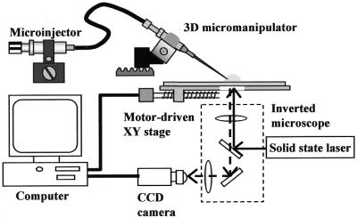
A motor driven micromanipulator, placed on an inverted fluorescence microscope (IX-70; Olympus, Japan), was used to adjust the 3-dimensional position of a capillary tip, from which a droplet of a DNA solution is dispensed using a microinjector and adsorbed onto the substrate (Fig. 1). The microinjector allows the pressure in the capillary to be controlled when the solution is sucked in and ejected. The microscope stage is automated with stepping motors and controlled by a computer, precisely locating the capillary tip on the substrate. The motions of the droplet and of the capillary tip are simultaneously monitored with a high sensitivity CCD camera (Color SensiCam; PCO Computer Optics, Germany) connected to a computer. While monitoring the droplet size can be adjusted by hand using a microinjector. Excitation light from a diode-pumped solid state laser (LCS-DTL-364, wavelength 473 nm; Laser-Compact, Russia), passed through an FITC filter set in the microscope, allows enhancement of the behavior of dyed particles and solution flow in the moving droplet.
Figure 1.
Schematic set-up of the meniscus motion control system employing a micromanipulated capillary for straightening DNA fibers.
Slide silanization
Coverslips (24 × 36 mm, 0.12–0.17 mm thickness; Matsunami Glass, Japan) were immersed in 1 N HCl solution for 1 h. They were then rinsed in deionized water (Millipore Auto-pure WQ-501; Yamato Scientific, Japan) and dried. The clean coverslips were silanized by immersing them in a commercial water repellent (Super Rain-X Plus; Nishikinodo, Japan) for 10 s and then rinsed in 99.5% ethanol. The silanized coverslips were dried using an air blower and used immediately. All the above operations were conducted at room temperature. In order to investigate the influence of the silanizing agent on straightening, coverslips modified using a conventional silanization method (14) were also employed: the cleaned coverslips were silanized by soaking in 5% dimethyldichlorosilane (DDS) (code no. 02309-62; Nacarai Tesque, Japan) in chloroform for 1 min at room temperature and then dried.
DNA preparation
Lambda phage DNA (48.5 kb, code no. DNA-001; Toyobo, Japan) was suspended at 400 µg/ml in TE buffer (10 mM Tris–HCl and 1 mM EDTA, pH 8.0). A working solution was prepared (100 µl) containing 40 ng/µl λ DNA and 0.2 µM YOYO-1 DNA dye (catalog no. Y-3601; Molecular Probes), also in TE. In addition, in order to demonstrate genomic DNA combing, straightening of total genomic DNA from bacteria was also performed. Total Thermus thermophilus HB8 genomic DNA (code no. 3071; Takara Shuzo, Japan), which was confirmed to contain >20 kb DNA by electrophoresis, was suspended at 203 µg/ml in TE. A working solution was prepared (10 µl) containing 4 ng/µl DNA fragments and 0.1 µM YOYO-1 in TE.
Optical image analysis
To slow photobleaching, an enzymatic oxygen scavenging system was employed on the prepared slide: 50 µg/ml glucose oxidase (code no. 168-30; Nacalai Tesqe, Japan), 15 µg/ml catalase (catalog no. 219261; Calbiochem) and 0.1% glucose in TE buffer, pH 8.0. An aliquot of 10 µl of this solution was dispensed on a microscope slide and a coverslip was placed on it with the prepared face downward. After the edge of the coverslip was sealed with nail polish, the prepared slide was observed by means of a fluorescence microscope (BX-52; Olympus, Japan). The trends of the straightened DNAs were observed through a 20× objective lens and details, such as the length of the straightened DNAs and background noise, were assessed with a 100× lens.
DNA straightening
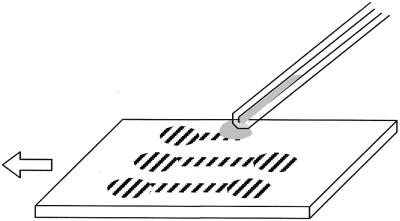
An aliquot of 5 µl of a working DNA solution was sucked into a glass capillary (diameter 1 mm, length 100 mm; Narishige, Japan) by means of a microinjector. After the capillary tip was set 10–30 µm from the coverslip surface at the starting point of combing, a droplet of the solution was dispensed between the tip and the substrate, as shown in Figure 2. The droplet size, monitored through a microscope, was adjusted to ∼0.5 mm in diameter (0.2 µl volume) using the injector. On dispensing, the droplet has to remain in contact with the solution in the capillary since the surface tension of the solution allows the shape and volume of the droplet to be controlled precisely during droplet motion. The microscope stage was then worked in a straight line at a constant displacement rate. This stage operation provides a straight trace of the moving droplet on the coverslip since the droplet follows the motion of the capillary tip, because of surface tension and the tendency of the substrate to repel water. Consequently, meniscus motion, caused by the droplet motion, produces straightened DNAs on the trace.
Figure 2.
Illustration of the procedure for straightening DNAs using meniscus motion control. A droplet, whose size is adjusted by the microinjector, is dispensed and sandwiched between the capillary tip and the substrate. The droplet follows the tip because of its surface tension while the substrate is moved in a straight line in the direction of the arrow. Striped areas on the substrate represent traces of the droplet where DNAs have been straightened because of meniscus motion.
The influence of the displacement rate on reproducibility of straightening was evaluated at 0.6, 1.5, 6.0 and 15 cm/min using working solutions of λ DNA. In the evaluation, three traces, 5 mm in length, ∼0.5 mm in width and in parallel at a 5 mm spacing, were drawn on a coverslip at each displacement rate. Then the frequency of fibers, which were sufficiently straightened in a 0.5 × 2 mm2 area of a trace between its starting and end points, was measured. While all the operations above were conducted at 20°C, the influence of environmental humidity was determined since water adsorption on the surface inhibits repulsion of the droplet. Thus, combing was conducted in environments of >60% and <40% humidity.
Behavior of the straightened DNAs, with respect to differences in origin of the DNA and in the silanizing agent, was investigated using our combing method in a low humidity environment. Straightening of the genomic DNA fragments from the bacteria was performed on coverslips coated with Rain-X. On the other hand, for the investigation of different silanizing agents, λ DNA was combed on coverslips coated with DDS.
Flow visualization
A suspension of 1 µm microspheres (streptavidin-coated fluoresbrite YG carboxylated microspheres, catalog no. 24161; Polysciences), whose concentration was adjusted to ∼4 × 10⁴ spheres/µl, was prepared in TE buffer (pH 8.0). Similar to the method used for DNA straightening, droplets of the suspension were moved and the motions of the microspheres and of the droplet contour, which are induced by circulating flow in the droplets, were simultaneously captured with a CCD camera via an inverted microscope. Capturing each moving sphere on video indicates the direction and rate of flow of the solution in the droplet. By focusing gradually on layers from the substrate surface to the top of the droplet, this visualization allows the behavior of the microspheres in each layer to be recorded. The motion of the microspheres was enhanced by excitation of the fluorescent dye using a solid-state laser; once adsorbed on the surface the microspheres are conveyed in accordance with the surface motion and, as a result, projected from the droplet. A normal light source and the laser were simultaneously used to visualize the droplet and the microspheres, since knowledge of the contour of the droplet is required to distinguish adsorbed microspheres from floating ones.
RESULTS
Straightened DNA variation
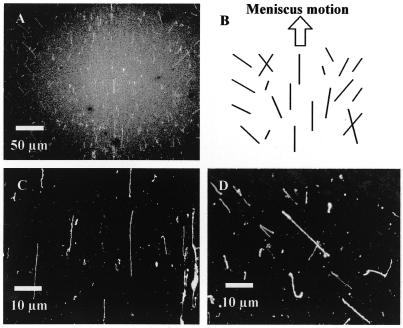
Figure 3A shows an overview of the combing area with a trace of a DNA solution droplet having moved at a displacement rate of 15 cm/min. This combing was conducted in a low humidity environment and the tendency of straightened DNAs is schematically shown in Figure 3B. In the center of the trace, sufficiently straightened DNAs are aligned parallel to the direction of droplet motion (Fig. 3C). At the sides of the trace, on the other hand, straightened DNAs are slanted to the outside of the trace as the droplet moves (Fig. 3D). In addition to straightened DNAs, DNAs slanted randomly, crossing each other or bent are occasionally found, while no such DNA is observed in the central area.
Figure 3.
Straightened λ phage DNAs, combed by meniscus motion control in a <40% humidity environment. These images were captured by a fluorescence microscope utilizing a high sensitivity cooled CCD camera. (A) Overview of a trace of a droplet moved on a coverslip, observed through a 20× objective lens. (B) Schematic of the trend of straightened DNAs in the trace, illustrated on the basis of the direction of meniscus motion and the center line of the trace. (C) Detail of straightened DNAs, observed in the center area of the trace and magnified with a 100× objective lens. (D) Slanted, straightened DNAs seen in the right of the trace.
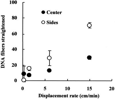
The number of distinctly straightened DNAs of ∼21 µm, which is close to the standard length of dynamically combed λ DNAs (10), was counted (Fig. 4). For this, the visual field of the microscope was adjusted to scan the restricted area and then straightened DNAs found in the center and at both sides of a trace were individually counted. This is because the stretching behavior is markedly different depending on the distance from the center line of the trace. It was shown that the number of straightened DNAs increases consistently with the rate of motion. The maximum standard deviation of the numbers obtained was 10.2 fibers/coverslip. Thus, the high reproducibility of our method of straightening DNAs was confirmed experimentally. With regard to the quality of the straightened DNAs, a motion rate of <6 cm/min frequently provided poorly straightened or folded DNAs and a high background signal. At a rate of <1.5 cm/min, few straightened DNAs were obtained, though at a rate >6 cm/min, shortened DNAs segmented by the shear force of the rapid flow were observed.
Figure 4.
Influence of the displacement rate of meniscus motion on the number of straightened DNAs. Blank circles represent the numbers of straightened DNAs found in both sides of the traces and filled circles are those found in the center area. The numbers are averages counted in three traces on a coverslip. Bars at the circles indicate standard deviation.
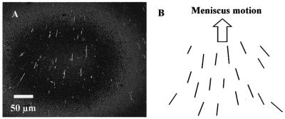
In a high humidity environment, DNA combing provides, as shown in Figure 5A, a straightened DNA pattern in distinct contrast to the view provided in Figure 3A. As the droplet moves, the directions of all the straightened DNAs are biased to the center line of the trace (Fig. 5B). The marked difference between Figures 3A and 5A is that no crossed or randomly slanted DNAs are found in the latter.
Figure 5.
Straightened λ phage DNAs combed by meniscus motion control in a >60% humidity environment. (A) Overview of a trace of a droplet moved on a coverslip, observed via a 20× objective lens. (B) Schematic of the tendency of straightened DNAs in the trace, illustrated on the basis of the direction of meniscus motion and the center line of the trace.
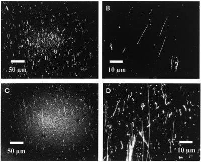
Figure 6 shows the behavior of DNAs straightened using a droplet motion of 15 cm/min with respect to differences in silanizing agent and the origin of the DNA. Lambda DNA was successfully straightened on a coverslip coated with DDS (Fig. 6A and B), similarly to the straightening on coverslips coated with Rain-X. The tendency for DNA slanting and the yield of straightened DNAs on the DDS-coated coverslips are consistent with those on Rain-X-coated coverslips. The genomic DNA fragments of T.thermophilus HB8 were also successfully straightened, although large fragments of >100 kb tended to be entangled or bundled (Fig. 6C and D).
Figure 6.
Behavior of straightened DNA with respect to differences in surface modification of substrates and in the origin of DNA. (A) Straightened λ phage DNAs; overview of a trace of a droplet moved on a coverslip coated with DDS. (B) Detail of the straightened phage DNAs. (C) Straightened genomic DNA of T.thermophilus HB8; overview of a trace. (D) Detail of the straightened genomic DNAs.
Visualized flow analysis
Solution flow was observed in detail in a droplet moved with a capillary tip on a hydrophobic surface. In the video images of a layer close to the substrate, all the microspheres moved from the advancing edge of the droplet to its receding edge. At the same time, some microspheres moved parallel to the contour of the droplet and others moved rapidly in a straight line toward the receding edge because of adsorption to the surface. Such adsorption was frequently observed at both edges, although the frequency was higher at the receding edge than at the advancing edge. In addition, aggregation of the microspheres, piled up at the center of the meniscus at the receding edge, was observed. On the other hand, the video images captured by focusing on an upper layer of the droplet showed that the microspheres in the upper layer were moving toward the advancing edge, in contrast to those in the surface layer. In both low and high humidity environments no differences in motion of the microspheres were observed.
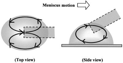
Based on these observations, suspension flow in the moving droplet was classified into two types of circulation behavior: one is circulation between the center line and both edges of the droplet (Fig. 7A), while the other is between the bottom and the top of the droplet, as shown in Figure 7B. The direction of flow on the surface was contrary to the droplet motion while as the distance from the surface increased the direction was gradually inverted.
Figure 7.
Illustration of solution flows in a droplet moved with a capillary tip. The top view shows two circulating flows, from the center to both sides of the droplet and then returning to the center. The side view illustrates a one-directional circulating flow from the bottom to the top of the droplet.
DISCUSSION
It has been shown that our combing method has high reproducibility and accuracy regarding the adjustable alignment of straightened DNA fibers. Furthermore, it has been indicated that these advantages of our method are unaffected by differences in the method of silanization or origin of the DNA if the substrate surface is hydrophobic, which allows DNA solutions to be sufficiently repelled. Simultaneously, the present experiments have provided considerable data valuable to the analysis of the behavior of DNAs straightened by a moving meniscus. In the following we analyze this behavior, focusing on the relationship between the alignment of straightened DNAs and the circulation flow induced in a droplet by the meniscus motion.
In the conventional mechanism of DNA combing utilizing a receding meniscus, the stretching of DNA fibers, previously adsorbed at their ends on a substrate surface, occurs in the interface between the meniscus and the surface. After adsorption, the DNAs are stretched by the accompanying interface motion, which is caused by the receding meniscus. In the case that the receding meniscus is involved in a laminar flow whose interface spreads widely, most of the absorbed DNAs become parallel to each other and are straightened in the direction of interface motion. This is because the interface is assumed to be straight due to its large curvature radius. In addition, one end of a straightened DNA first adsorbed on the surface is always closer to the starting point of interface motion than the other end.
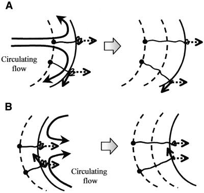
In our combing method, the combing mechanism itself is similar to those of the conventional methods, except that the interface has a minute curvature radius. As the interface moves, however, circulation flows in a moving droplet appear parallel to the droplet contour because of the use of a minute droplet for combing. Thus, DNAs in the edge areas are stretched to the moving interface and are simultaneously stretched with the circulation flows. We have considered that the bias due to the circulation flow causes local variation in slanting of the straightened DNAs. The biased direction changes in relation to position in the droplet because of its round interface. Based on flow analysis, the possible biasing can be classified in two cases: (i) one is away from the center line at the advancing edge of the droplet; (ii) the other is toward the center line at the receding edge (Fig. 8). If DNA straightening occurs at the advancing edge of the interface, the direction of stretching is biased away from the center line in the sides of the trace. Consequently, the DNAs are straightened slanting toward each side, as illustrated in Figure 8A. In contrast, if straightening occurs at the receding edge, the direction is toward the center line. Hence, case (ii) results only in DNAs straightened at a slant toward the center line (Fig. 8B).
Figure 8.
Influence of the circulation flows on the behavior of DNAs stretched by meniscus motion. Bold arrows represent circulating flows induced in the droplet, dotted arrows the flow directions corresponding to droplet motion and solid arrows the directions biased by the circulation flows on the surface. Large dots are adsorption points of the DNAs, broken lines indicate traces of the preceding interfaces and round solid lines show the interfaces between the meniscus and substrate. The meniscus moves from left to right in this illustration and the results are shown in the right figures. (A) Behavior of the DNAs adsorbed at the advancing edge of the droplet and then stretched by meniscus motion. The stretching direction slants towards the side of the droplet due to the circulation flow. (B) In contrast to the stretching at the advancing edge, at the receding edge the stretching direction slants towards the center of the droplet due to the circulation flow.
The result of combing in a high humidity environment (Fig. 5A) can be explained by the occurrence of case (ii). On the other hand, combing conducted in a low humidity environment provides a result markedly different from that described above (Fig. 3A). If it is possible that both cases (i) and (ii) are involved in low humidity combing, this could explain the variations in slanting: in the case of the crossed DNAs, it is thought that one DNA in the advancing edge was straightened first and, subsequently, another in the receding edge straightened near the first one. This assumption is supported by the fact that bent or randomly slanted DNAs have also been observed after combing in a low humidity environment.
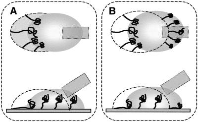
While in agreement with the behavior taking place during simultaneous occurrence of cases (i) and (ii), the results observed in a low humidity environment are inconsistent with the combing mechanism reported by Bensimon et al. (15). This mechanism only allows DNAs to be stretched in a receding meniscus. To explain this inconsistency, we have focused on the differences in humidity in the venue where the combing was performed. In a humid environment, it is assumed that a silanized surface becomes poorly hydrophobic, microscopically; a thin, aqueous layer covers the surface. As a DNA solution droplet moves on the surface, the droplet wets the surface slightly and then leaves a little solution on the surface. In combing, it is necessary for the DNAs to be stretched by meniscus motion and then to be fixed by drying. While the DNAs in the receding edge satisfy this condition, those in the advancing edge are unfixed since they have been soaked in the solution. Hence, in a humid environment, only the DNAs in the receding edge are consistently straightened, as shown in Figure 9A. On the other hand, in a dry environment, a silanized surface is sufficiently hydrophobic, since it is difficult for the surface to adsorb aqueous molecules. It is thought that a DNA solution droplet can move on the surface without wetting; the DNAs, adsorbed at their ends, instantaneously fix along their contours as the droplet moves, whether they are located in the receding edge or not (Fig. 9B).
Figure 9.
Behavior of DNAs straightened by droplet motion dependent on surface characteristics. Dotted lines represent the location of the preceding interface in which the extremities of the DNAs have been adsorbed on the surface and solid entangled lines represent stretching DNAs. Gray areas are those wetted by the droplet or soaked in DNA solution. The upper figures are top views of droplet movement and the lower ones side views. (A) Straightening DNAs on a poorly hydrophobic surface. Fixation of the contours of the DNAs, in accordance with their stretching, occurs solely at the receding edge since no fixation is allowed to occur in the wetted areas. (B) Straightening on a highly hydrophobic surface. Fixation occurs at both the advancing and receding edges of the droplet since water repulsion promotes fixation at the advancing edge.
Acknowledgments
ACKNOWLEDGEMENTS
We thank Dr Shigeru Sugiyama for helpful discussions. This study was performed with the help of Special Coordination Funds from the Ministry of Education, Culture, Sports, Science and Technology of the Japanese Government, and was supported in part by the research program of the Bio-oriented Technology Research Advancement Institution, Japan.
REFERENCES
- 1.Wiegant J., Wiesmeijer,C.C., Hoovers,J.M.N., Schuuring,E., d’Azzo,A., Vrolijk,J., Tanke,H.J. and Raap,A.K. (1993) Multiple and sensitive fluorescence in situ hybridization with rhodamine-, fluorescein- and comarin-labeled DNAs. Cytogenet. Cell Genet., 63, 73–76. [DOI] [PubMed] [Google Scholar]
- 2.Herrick J. and Bensimon,A. (1999) Imaging of single DNA molecule, application to high-resolution genomic studies. Chromosome Res., 7, 409–423. [DOI] [PubMed] [Google Scholar]
- 3.Bustamante C., Vesenka,J., Tang,C.L., Rees,W., Guthold,M. and Keller,R. (1992) Circular DNA molecules imaged in air by scanning force microscopy. Biochemistry, 31, 22–26. [DOI] [PubMed] [Google Scholar]
- 4.Hansma H.G., Bezanilla,M., Zenhausern,F., Adarian,M. and Sinsheimer,R.L. (1993) Atomic force microscopy of DNA in aqueous solutions. Nucleic Acids Res., 21, 505–512. [DOI] [PMC free article] [PubMed] [Google Scholar]
- 5.Wang W., Lin,J. and Schwartz,D.C. (1998) Scanning force microscopy of DNA molecules elongated by convective fluid flow in a evaporated droplet. Biophys. J., 75, 513–520. [DOI] [PMC free article] [PubMed] [Google Scholar]
- 6.Dekker D., Zeisei,D. and Zenobi,R. (1998) Near-field surface enhanced raman imaging of dye-labeled DNA with 100-nm resolution. Anal. Chem., 70, 2646–2650. [DOI] [PubMed] [Google Scholar]
- 7.Muramatsu H., Homma,K., Yamamoto,N., Wang,J., Sakata-Sogawa,K. and Shimamoto,N. (2000) Imaging of DNA molecules by scanning near-field microscope. Mater. Sci. Eng., 12C, 29–32. [Google Scholar]
- 8.Moers M.H.P., Kalle,W.H.J., Ruiter,A.G.T., Wiegant,J.C.A.G., Raap,J., De Grooth,B.G. and van Hulst,N.F. (1995) Fluorescence in situ hybridization on human metaphase chromosomes detected by near-field scanning optical microscopy. J. Microsc., 182, 40–45. [DOI] [PubMed] [Google Scholar]
- 9.Perkins T.T., Smith,D.E. and Chu,S. (1994) Direct observation of tube-like motion of a single polymer chain. Science, 264, 819–822. [DOI] [PubMed] [Google Scholar]
- 10.Bensimon A., Simon,A., Chiffaudel,A., Croquette,V., Heslot,F. and Bensimon,D. (1994) Alignment and sensitive detection of DNA by a moving interface. Science, 265, 2096–2098. [DOI] [PubMed] [Google Scholar]
- 11.Michalet X., Ekong,R., Fogerousse,F., Rousseaux,S., Schurra,C., Povey,S., Beckmann,J.S., Bensimon,A., Hornigold,M., van Slegtenhorst,M. and Wolfe,J. (1997) Dynamic molecular combing, stretching the whole human genome for high resolution studies. Science, 277, 1518–1523. [DOI] [PubMed] [Google Scholar]
- 12.Li J., Bai,C., Wang,C., Zhu,C., Lin,Z., Li,Q. and Cao,E. (1998) A convenient method of aligning large DNA molecules on bare mica surface for atomic force microscopy. Nucleic Acids Res., 26, 4785–4786. [DOI] [PMC free article] [PubMed] [Google Scholar]
- 13.Yokota H., Jhonson,F., Lu,H., Robinson,R.M., Belu,A.M., Garrison,M.D., Ranter,B.D., Trask,B.J. and Miller,D.L. (1997) A new method for straightening DNA molecules for optical restriction mapping. Nucleic Acids Res., 25, 1064–1070. [DOI] [PMC free article] [PubMed] [Google Scholar]
- 14.Maniatis T., Fritsch,E.F. and Sambrook,J. (1982) Molecular Cloning: A Laboratory Manual. Cold Spring Harbor Laboratory Press, Cold Spring Harbor, NY.
- 15.Bensimon D., Simon,A., Croquette,V. and Bensimon,A. (1995) Stretching DNA with a receding meniscus, models and experiments. Phys. Rev. Lett., 74, 4754–4757. [DOI] [PubMed] [Google Scholar]


