

Abstract

The bedding plane formed by sedimentation makes shale anisotropic. To clarify the influence of bedding on the hydraulic fracturing of shale, the fracture characteristics of bedding shale were first clarified by conducting a hydraulic fracturing experiment on large-scale shale samples with different bedding angles. Subsequently, combined with the experimental results, based on the theory of elasticity, a new fracture initiation criterion for shale hydraulic fracturing considering its anisotropic characteristics was established. The influence of the bedding angle on the hydraulic fracture initiation pressure and initiation angle was analyzed. The results showed that the pump pressure curve during hydraulic fracturing can be divided into four stages: continuous pressurization, internal pressure drop, internal pressure attenuation, and internal pressure equilibrium stage. Corresponding to the four stages of the pump pressure curve, the evolution of hydraulic fracture has four processes: microfracture development, fracture initiation, fracture propagation, and fracture network equilibrium process. When the direction of the maximum principal stress is perpendicular to the bedding, a complex fracture network is easily formed. Depending on whether the bedding plane is open or not, the modes of interaction between the hydraulic fractures and bedding plane could be divided into eight types. Hydraulic fractures initiate in two ways: from the matrix and from natural fractures. During fracturing, with the increase in the bedding angle, the initiation pressure decreases gradually and the initiation angle decreases first and then increases. The knowledge gained in this study can provide data and theoretical support for drilling direction design and fracture pressure evaluation in the field of hydraulic fracturing.
1. Introduction
With the shortage of conventional forms of energy and increasingly serious environmental problems, shale gas, as a clean energy, has important industrial value and strategic significance.1−3 The core technology in the exploitation of shale gas is hydraulic fracturing. Its principle is to use a high-pressure liquid to conduct volume fracturing on deep shale reservoirs to form a fracture network structure to produce stable industrial gas flow.4−7 Owing to the tightness and low permeability of shale, the fracture network formed after fracturing is the main channel for shale gas permeability. Therefore, the spatial fracture network structure formed after fracturing is the most important factor affecting the production rate of shale gas, which directly determines the success or failure of shale reservoir reconstruction.8−11
Scholars have made significant progress in establishing hydraulic fracturing networks for shale. In terms of theory, Hubbert and Wills12 conducted exploratory research on hydraulic fracturing and put forward the first fracture model based on the tensile strength. Haimson and Fairhurst13,14 proposed a theoretical model considering the effect of porous elasticity. Ito and Hayashi,15 Brenne et al.,16 and Cornetti et al.17 put forward many new theories for hydraulic fracturing.18−21 The failure criterion for hydraulic fracturing has been developed from the classical elastic criterion to porous elastic criterion, point stress criterion, fracture mechanics-based criterion, energy-based criterion, and other complex combination criteria.22 Along with the development of theory, hydraulic fracturing experiments have also achieved remarkable results. Several experimental studies have been conducted on influencing factors such as the in situ stress, natural fracture, temperature, fracturing fluid, and pumping mode in hydraulic fracturing.23,24
Hayashi and Ito,25 Warpinski and Teufel,26 Beugelsdijk et al.,27 and Zhou et al.28 showed that the stress around a deep shale is three-dimensional, the stress has a significant impact on the fracture shape after fracturing, and the high ground stress difference has an adverse effect on the formation of the complex fracture network. Lee et al.,29 Aydin,30 Blanton,31 and Wang et al.32 conducted experimental simulation research on the natural fractures in shale. The existence of natural fractures was found to cause stress concentration and affect the propagation of hydraulic fractures. The influence of natural fractures on whether a complex fracture network can be produced after fracturing is twofold, that is, it may cause leakage of the fracturing fluid to form simple fractures, and it may also make hydraulic fractures cross and form complex fractures. Kumari et al.,33,34 Xing et al.,35 Hou et al.,36 and Kang et al.37 conducted a series of studies on the effect of temperature on hydraulic fracturing; the results showed that when the reservoir temperature is high, the compressive strength, tensile strength, and failure mode of the shale vary, which directly influences the effectiveness of hydraulic fracturing. Beugelsdijk et al.,27 Akai et al.,38 Guo et al.,39 Zhou et al.,40 and Guo et al.41 summarized experimental results based on natural and artificial rock samples and provided influence laws of the fracturing fluid concentration, injection rate, pumping mode, and perforation mode on hydraulic fracturing.
Hydraulic fracturing is a multidisciplinary and multiphysical activity in underground systems.22 The hydraulic fracturing of shale has been a research hotspot for nearly half a century. However, the existing hydraulic fracturing theory is inconsistent with practical applications. In addition, most of the above studies were based on experimental and theoretical analyses of isotropic shale. In practice, the bedding plane formed by sedimentation makes shale anisotropic.42 Li43 concluded that the crack damage stress, crack initiation strain, and crack damage strain strongly depend on the bedding angle. Through a Brazilian splitting test and a three-point bending test, Jin et al.44 discussed the anisotropy in the fracture behavior of shale with respect to the bedding angle. Chalmers et al.45 investigated the nanopore system of gas shale using scanning electron microscopy and found large pores parallel to the bedding direction. Wang et al.46 concluded that the shear strength of shale varies with the bedding angle based on experimental data. This shows that the anisotropy caused by bedding is an important factor in the study of hydraulic fracturing.
The bedding plane affects the initiation pressure and propagation of hydraulic fractures.22 The prediction of the fracturing pressure in the process of hydraulic fracturing is a key research topic and an important basis for on-site hydraulic fracturing design. However, the above studies do not provide a definite relationship between the bedding anisotropy and fracture initiation pressure. Furthermore, the research results were mostly based on experiments conducted with artificial samples or small samples. The experimental samples showed some deviation from real shale reservoirs. Because of the difficulty in preparing shale samples with a bedding angle, there are a few experimental results on the hydraulic fracturing of large-size (400 mm) shale samples with different bedding angles. Therefore, it is necessary to conduct large-scale hydraulic fracturing experiments on shale with different bedding angles to explore the influence of bedding anisotropy on hydraulic fracturing.
In this study, we upgraded the original uniaxial geotechnical pressure testing machine in the laboratory. A true triaxial loading chamber was made in accordance with the use of a pump injection module, and a large-scale hydraulic fracturing experimental platform was built. To explore the influence of bedding on shale hydraulic fracturing, the outcrop shale of the Shuanghe section of Changning County, Yibin City, Sichuan Province, China (Longmaxi formation shale) was selected for the hydraulic fracturing experiments with different bedding angles. Combined with the experimental results, the effects of bedding changes on shale hydraulic fracturing experiments, including the internal pressure characteristics, fracture initiation pressure, and fracture morphology after fracturing, were analyzed. Subsequently, based on the theory of elasticity and considering the anisotropic characteristics of the shale of the Longmaxi formation, a new fracture initiation criterion was established, which could predict the fracture initiation pressure and initiation angle under different bedding angles. It can provide data support and theoretical basis for shale gas reservoir development.
2. Experimental Conditions and Contents
2.1. Experimental Equipment
A fracturing experiment was conducted using the upgraded hydraulic fracturing physical simulation system. The vertical stress was loaded by the original testing machine, and the lateral stress was loaded by two transverse jacks. This experimental system mainly includes a loading chamber module, a simulated in situ stress loading module, a hydraulic pump injection module, and an acoustic emission module, as shown in Figure 1.
Figure 1.

Hydraulic fracturing experimental system: (a) stereogram of the system and (b) schematic of the system.
Compared with the conventional testing machine, the experimental system has the following advantages:
-
(1)
Installing a spherical loading plate at the end of the jack, as shown in Figure 2, could eliminate the eccentric loading stress concentration phenomenon caused by the inclination of the end face of the large-size sample. After testing, the device had a good loading effect on the sample with the flatness of the end face being less than 5° (the included angle between the normal of the end face and the axis of the sample).
-
(2)
The loading force of the testing machine in three directions was 5000 kN. The testing machine was equipped with various sizes of backing plates, which could be used for the fracture simulation of samples with a size range of 200–400 mm.
-
(3)
A gas–liquid booster pump was used in the pumping module as the power source, and an intermediate container was incorporated into the module. The maximum pumping pressure was 100 MPa.
Figure 2.

True triaxial loading chamber: (a) top view of the loading chamber and (b) stereogram of the loading chamber.
2.2. Experimental Sample
In this study, the outcrop shale of the Longmaxi formation was selected as the research object. The outcrop shale sample is located in the Shuanghe section of Changning County, Yibin City, Sichuan Province. Cube-shaped shale samples with different bedding angles and side lengths of 400 mm were prepared, as shown in Figure 3. Before the hydraulic fracturing experiment, the basic mechanical parameters of the shale were measured. The specific parameters are given in the author’s previous research.42
Figure 3.

Shale sampling: (a) sampling site and stratigraphic histogram, (b) outcrop shale samples from the site, and (c) shale samples with a side length of 400 mm.
2.3. Experimental Scheme
In the experiment on the shale samples, the in situ stress state, pump pressure displacement, fracturing fluid viscosity, and temperature were kept unchanged. Considering the influence of bedding angle, shale hydraulic fracturing experiments with different bedding angles were designed to explore the influence of bedding angle on the initiation mode and propagation law of the hydraulic fractures.
A hydraulic fracturing experiment of the horizontal well was designed, the simulated wellbore was located at the center of the end face of the sample, and the hole was sealed with cement mixture. The angle between the bedding and horizontal planes is defined as the bedding angle β. The overburden pressure, horizontal maximum principal stress, and horizontal minimum principal stress are denoted by σV, σH, and σh, respectively. Six groups of hydraulic fracturing experiments with different bedding angles were designed in this study. Table 1 presents the specific experimental parameters. Figure 4 shows the experimental loading mode.
Table 1. Experimental Categories and Parameters.
| in situ
stress/(MPa) |
|||||||
|---|---|---|---|---|---|---|---|
| experiment category | sample number | bedding angle β/(°) | σV | σH | σh | horizontal stress difference coefficient | pumping mode |
| hydraulic fracturing with different bedding angles | L-1-1 | 0 | 20 | 10 | 10 | 0 | constant-displacement pressurization |
| L-1-2 | 13 | ||||||
| L-1-3 | 23 | ||||||
| L-1-4 | 67 | ||||||
| L-1-5 | 77 | ||||||
| L-1-6 | 90 | ||||||
Figure 4.

Experimental loading mode: (a) schematic of wellbore sealing and (b) three-dimensional load acting on the horizontal well.
3. Analysis of Hydraulic Fracture Initiation and Propagation Process
3.1. Characteristics of Pump Pressure Curve in Wellbore during Fracturing
During fracturing, the fracturing fluid is continuously injected into the closed wellbore, causing the pressure in the wellbore to increase gradually. When the pressure reaches the critical value, hydraulic fractures in the shale sample begin to initiate and propagate. The following is the real-time monitoring of the wellbore pressure during fracturing and the analysis of the various stages of the wellbore pressure in the entire process.
Two groups of experimental results with bedding angles of 0 and 90° were selected to analyze the pump pressure curve. Among them, the fracture initiation pressure at a bedding angle of 0° was the highest and that at a bedding angle of 90° was the lowest. Figure 5a shows the pump pressure curve of sample l-1-6. The sample broke at 31.70 s, and the initiation pressure was 6.61 MPa. By analyzing the characteristics of the pump pressure curve, the pump pressure curve can be divided into four stages: (1) Continuous pressurization stage (0.00–31.70 s), which can be further divided into front and back sections. In the front section, with the injection of the fracturing fluid, the pressure in the wellbore increases rapidly. In the back section, the internal pressure fluctuates; however, the overall trend is upward. (2) Internal pressure drop stage (31.70–36.25 s). After the pump pressure curve reaches the peak, the sample breaks, and the pump pressure decreases rapidly. (3) Internal pressure attenuation stage (36.25–50.09 s). The pump pressure curve shows a zigzag-like fluctuating downward trend. (4) Internal pressure equilibrium stage (50.09–80.00 s). At this stage, the pump pressure curve is flat, stable at a fixed value, and fluctuates in a narrow range.
Figure 5.

Pump pressure curve. (a) Pump pressure curve of sample L-1-6. (b) Pump pressure curve of sample L-1-1.
Figure 5b shows the pump pressure curve of sample l-1-1. The sample broke at 61.22 s, and the initiation pressure was 41.87 MPa. During the continuous pressurization stage (0–61.22 s), the curve continues to rise. The curve has an evident rise in the front section of the continuous pressurization stage, which is considered to be due to the inflow of the fracturing fluid in the wellbore before fracturing. During the internal pressure drop stage (61.22–64.10 s), the curve drops instantaneously, and the internal pressure decreases from 41.87 to 27.11 MPa. During the internal pressure attenuation stage (64.10–80.53 s), the curve shows a fluctuating downward trend. During the internal pressure equilibrium stage (80.53–100 s), the curve tends to be flat. A comparison between the pump pressure curves of samples L-1-1 and L-1-6 during fracturing shows a consistent change trend. The pump pressure curve can be divided into four stages: continuous pressurization stage, internal pressure drop stage, internal pressure attenuation stage, and internal pressure equilibrium stage.
3.2. Analysis of Hydraulic Fracture Evolution Process
The high-pressure liquid stored in the wellbore is the only source of energy required for the initiation and propagation of hydraulic fractures; therefore, the change in the liquid pressure in the wellbore reflects the evolution process of the hydraulic fractures. Combined with the variation law of the pump pressure curve, the evolution of the hydraulic fractures can be summarized into four processes.
In the continuous pressurization stage, the shale matrix around the wellbore is squeezed by the fracturing fluid to produce microfractures. However, no complete hydraulic fracture is formed at this time. The formation of microfractures provides space for the fracturing fluid injected into the wellbore; therefore, the pump pressure curve fluctuates. However, due to the failure to form a complete fracture, the space provided is limited; therefore, the pump pressure generally increases with the continuous injection of the fracturing fluid. This fracture evolution process can be called the microfracture development process.
In the internal pressure drop stage, the internal pressure reaches the bearing limit of the specimen. Under the action of the internal pressure, microfractures develop into hydraulic fractures and expand outward from the inside of the wellbore. The formation of hydraulic fractures makes the connected space in the wellbore expand instantaneously; therefore, the pump pressure curve drops rapidly. This process can be called the fracture initiation process.
In the internal pressure attenuation stage, hydraulic fractures propagate through natural fractures or bedding planes, forming complex fracture networks. The increasing number of fracture channels in shale weakens the storage capacity of the fracturing fluid; this is reflected in the zigzag-like decrease in the pump pressure curve. This process is called the fracture propagation process.
In the internal pressure equilibrium stage, the hydraulic fractures propagate to the end face of the sample, a complete fracture channel is formed in the shale, and the fracturing fluid flows out of the sample from the wellbore along the fracture channel. Under the action of the internal fracturing fluid and in situ stress, the fracture channel will form a dynamic balance between opening and closing. This leads to changes in the wellbore pressure; therefore, the pump pressure curve is flat and accompanied by small fluctuations. This process can be called the fracture network equilibrium process.
4. Effect of Bedding Plane on Shale Hydraulic Fracturing
4.1. Effect of Bedding Angle on Initiation Pressure during Fracturing
The initiation pressure and experimental phenomena of the six groups of samples during fracturing are recorded and summarized:
-
(1)
The hydraulic fracture initiation pressure of the sample with a bedding angle of 0° was 41.87 MPa. A complex fracture network is formed at the end of the simulated wellbore. There was a continuous cracking sound during fracturing and a loud noise at the moment when the sample broke.
-
(2)
The hydraulic fracture initiation pressure of the sample with a bedding angle of 13° was 30.85 MPa. Hydraulic fracture initiation along the bedding direction and several new hydraulic fractures crossing the bedding plane were observed on the side.
-
(3)
The hydraulic fracture initiation pressure of the sample with a bedding angle of 23° was 12.02 MPa. Hydraulic fractures initiated and propagated along the bedding fractures. New hydraulic fractures were observed on the side after fracturing. Fracturing was accompanied by a continuous weak cracking sound.
-
(4)
The hydraulic fracture initiation pressure of the sample with a bedding angle of 67° was 10.72 MPa. A single hydraulic fracture was observed along the bedding direction on the side, and a large amount of fracturing fluid overflowed.
-
(5)
The hydraulic fracture initiation pressure of the sample with a bedding angle of 77° was 9.08 MPa. A single hydraulic fracture could be observed along the bedding direction.
-
(6)
The hydraulic fracture initiation pressure of the sample with a bedding angle of 90° was 6.61 MPa. A single vertical hydraulic fracture could be observed along the bedding direction, with a large fracture width.
Figure 6 shows the hydraulic fracturing pump pressure curve of the shale at different bedding angles. The fracture initiation pressure tends to decrease with the increase in the bedding angle. The characteristics of the pump pressure curve vary with the increase in the bedding angle, which is embodied in two stages: a continuous pressurization stage and an internal pressure equilibrium stage. In the continuous pressurization stage, the pump pressure curve of large-bedding-angle sample (L-1-1/2/3) has an evident fluctuating rising process before reaching the fracture initiation pressure, while the pressure fluctuation of the small-bedding-angle sample (L-1-4/5/6) sample is less. In the internal pressure equilibrium stage, the samples with a small bedding angle after fracturing could maintain a high pressure in the wellbore, that is, they had a high liquid storage capacity.
Figure 6.

Six groups of experimental pump pressure curves: (a) sample L-1-1, (b) sample L-1-2, (c) sample L-1-3, (d) sample L-1-4, (e) sample L-1-5, and (f) sample L-1-6.
4.2. Analysis of Hydraulic Fracture Morphology of Shale with Bedding Plane
The fracture morphology on the outer surface of the shale before and after fracturing was recorded. To facilitate visual comparison, the six outer surfaces of the sample were spliced according to the spatial position and numbered A, B, C, D, E, and F, as shown in Figure 7. Samples with bedding angles of 0 and 90° were selected to analyze the hydraulic fracture morphology.
Figure 7.

Schematic of the six-side splicing of the sample.
Figure 8 shows a comparison of the surface fractures before and after fracturing in the 0°-bedding-angle sample. Figure 8a shows four natural fractures before fracturing. Along the bedding direction, fracture I runs through the four faces of ABCD. Fracture II is perpendicular to the bedding direction, runs through face F, and intersects with fracture I on face B. Fractures III and IV are small, located at faces B and D, respectively, and intersect with fracture I.
Figure 8.

Surface fracture comparison of sample L-1-1 before (a) and after (b) fracturing.
Figure 8b shows the hydraulic fracture after fracturing. Four of the five natural fractures were opened. Fracture I is opened according to the original track. The natural fracture II is opened, and a new horizontal bedding hydraulic fracture IX is formed on the D face in the process of propagation. Fracture III is opened and propagates to face F. Fracture IV is not opened. In the middle of D face, a fracture network structure with multiple intersecting fractures is formed. Fractures VI and VII are along the horizontal bedding direction. The propagation of fracture VIII is along the lower left direction, with an included angle of 28° with the bedding plane. The propagation of fracture V is along the right upper direction, intersects with the crack I, and passes through crack I to continue to expand upward.
Figure 9a shows the fractures before fracturing in the 90°-bedding-angle sample. The sample surface before fracturing has five natural fractures. Fractures I and II are bedding fractures that run through the entire face of AECF. Fractures III, IV, and V are small, perpendicular to the bedding direction, and located on faces C, F, and A, respectively.
Figure 9.

Surface fracture comparison of sample L-1-6 before (a) and after fracturing (b).
Figure 9b shows that the fracture shape of the 90°-bedding-angle sample after fracturing is simple. The natural fractures III, IV, and V in the vertical direction of bedding are not opened. After fracturing, a large fracture penetrating the entire sample is formed along the bedding direction. The part of fracture I on the E, C, and F faces is opened, and the part of fracture II on the E, A, and F faces is opened. Two inclined hydraulic fractures VI and VII are formed, located on the E and F faces, respectively. Hydraulic fractures VI and VII connect two bedding fractures I and II to form a large fracture through the sample. The large fracture is composed of open natural fractures and new hydraulic fractures.
In summary, the bedding plane plays a leading role in the hydraulic fracture morphology after fracturing. The fracture morphology of the 0°-bedding-angle sample after fracturing is complex and that of the 90°-bedding-angle sample after fracturing is simple. The maximum stress difference in the experimental design is 10 MPa. The direction of the maximum principal stress is vertical. When the bedding angle is 0°, the maximum principal stress is perpendicular to the bedding direction. In the process of bedding fracture propagation, the fractures easily pass through the bedding plane under the action of the maximum principal stress and then open new bedding fractures. Bedding fractures and new hydraulic fractures constitute a complex fracture network structure after fracturing. When the bedding angle is 90°, the maximum principal stress is consistent with the bedding direction. Bedding fractures easily propagate along the original track to form a single large crack. The experimental results showed that when the direction of the maximum principal stress is consistent with the bedding, a simple single fracture is more easily formed, and when the direction of the maximum principal stress is perpendicular to the bedding, a complex fracture network is more easily formed.
4.3. Interaction Mode between Hydraulic Fractures and Bedding Plane
The bedding plane is a weak strength plane in the shale matrix. When hydraulic fracture propagation intersects with the bedding plane, different interaction modes are produced. These modes work synchronously to form a complex fracture network structure.
Figure 10a shows the hydraulic fracture network in sample L-1-1 on its D face. With the increase in the internal pressure, hydraulic fractures initiate and propagate along the bedding direction. Under the influence of longitudinal stress difference, hydraulic fractures deflection cross the bedding plane along the direction of the maximum principal stress. The deflected hydraulic fractures intersect with a new bedding plane, opening a new bedding plane. Hydraulic fractures interact with the bedding plane, repeat the above process, and finally form a complex fracture network structure. The interaction between hydraulic fractures and the bedding plane can be divided into two categories: where the bedding plane does not open or it opens. The process can be divided into eight types: (a) Stopping after intersecting the bedding plane; (b) crossing directly after intersecting the bedding plane; (c) deflection crossing after intersecting the bedding plane; (d) opening the bedding surface and stopping after intersecting the bedding plane; (e) open the bedding plane and crossing directly after intersecting the bedding plane; (f) opening the bedding plane and deflection crossing after intersecting the bedding plane; (g) offset crossing after intersecting the bedding plane; and (h) offset and then deflect crossing after intersecting the bedding plane. Figure 10b shows the corresponding schematics.
Figure 10.

Modes of interaction between hydraulic fractures and bedding plane: (a) fracture morphology of sample L-1-1 on D face and (b) schematic of the interaction modes.
5. Analysis of Hydraulic Fracture Initiation Considering Bedding Anisotropy
5.1. Hydraulic Fracture Initiation from Shale Matrix
Regardless of the filtration effect and temperature effect of the fracturing fluid, a point of stress around the wellbore during the fracturing of the shale reservoir is mainly affected by the stress component caused by the far-field in situ stress and the stress component caused by the internal pressure of the fracturing fluid.
The axis of the horizontal well in the formation is consistent with the direction of the minimum principal stress. The cross section of the wellbore was selected to establish a coordinate system and a polar coordinate system, as shown in Figure 11, where X and Y are the horizontal and vertical directions, respectively, and Z is the axial direction of the wellbore. Since the axial dimension of the wellbore is much greater than the radial dimension, the strain in the Z direction is assumed to be 0. All of the displacement vectors are in the XOY plane, which simplifies the complex three-dimensional (3D) problem into a plane strain problem. Thus, the in situ stress components in the XYZ coordinate system are as follows
 |
1 |
here, σV, σH, and σh are the overburden pressure, horizontal maximum principal stress, and horizontal minimum principal stress in situ stress, respectively; σxx, σyy, and σzz are the stress components in the direction of the three coordinate axes in the XYZ coordinate system, respectively.
Figure 11.

Three-dimensional coordinate system: (a) space rectangular coordinate system and (b) polar coordinate system of the wellbore cross section.
According to the theory of elastic mechanics, by the superposition of the in situ stress, the stress components due to the in situ stress near the wellbore can be obtained as follows
 |
2 |
where θ is the angle between a point and the x-axis in the polar coordinate system; ρ is the distance from a point to the wellbore axis; R is the wellbore radius; μ is Poisson’s ratio; σρ(1), σθ, σz(1), τρθ, τθz(1), and τρz are the radial stress component, circumferential stress component, and axial stress component due to the in situ stress, respectively.
According to the theory of elastic mechanics, the stress component due to the internal pressure of the fracturing fluid near the wellbore can be calculated. Referring to the laboratory experiment, it is assumed that the inner wall of the wellbore is smooth and that the internal pressure does not decay along the wellbore axis. Notably, during on-site hydraulic fracturing operation, the horizontal wellbore is typically very long, and the inner wall cannot be considered completely smooth. In addition, due to the uneven casing interface and the influence of devices, such as occluders, the tensile stress along the axial direction of the wellbore decreases. According to Haimson,47 the axial stress σz* should be corrected, and the correction coefficient is 0.9 < c <1. The stress components due to the internal pressure near the wellbore can be expressed as follows
 |
3 |
where PW is the internal pressure of the wellbore fracturing fluid; σρ(2), σθ, and σz(2) are the radial stress component, circumferential stress component, and axial stress component due to the internal pressure, respectively; and σz is the corrected axial stress component.
According to the superposition principle, the stress distribution near the wellbore under the action of the in situ stress and internal pressure can be obtained as follows from eqs 2 and 3
 |
4 |
where σρ, σθ, σz, τρθ, τθz, and τρz are the radial stress component, circumferential stress component, and axial stress component near the wellbore in the polar coordinate system, respectively.
A point on the wellbore wall, ρ = R. Therefore, the stress field distribution on the wellbore is
 |
5 |
According to eq 5, there is only normal stress and no shear force in the three planes perpendicular to σρ, σθ, and σz; therefore, σρ, σθ, and σz are the three principal stresses at a point on the wellbore wall.
| 6 |
According to the maximum circumferential failure criterion, the rock fails when the maximum tensile stress reaches the rock tensile strength. From eq 6, it can be found that σ3 is most likely the maximum tensile principal stress, that is, the maximum tensile stress at a point on the wellbore wall is a function of θ.
| 7 |
The sedimentary characteristics lead to the development of the weak bedding plane of the shale, and the tensile strength along the bedding plane at different angles (different splitting angles) shows anisotropic characteristics. According to the author’s previous research, the least-square fitting is made for the tensile strength of the outcrop shale sample in the 0–90° splitting direction of the Longmaxi formation, as shown in Figure 12.42 The tensile strength of the shale as a function of the splitting angle α can be obtained as follows:
| 8 |
From eq 8, the first-order coefficient of the function is low, and the function value is less affected by the first-order term; therefore, the first-order term is omitted. According to the symmetry, the tensile strength eq 9 of the shale under different splitting angles can be obtained. Figure 13 shows the change trend.
| 9 |
Combined with eqs 7 and 9, it is specified that the tensile stress is negative and the compressive stress is positive. Therefore, the hydraulic fracture initiation criterion is as follows
| 10 |
In the same coordinate system, the relationship between the bedding and splitting angles is deduced in eq 10. σθ is the maximum tensile principal stress at a point on the wellbore wall. The hydraulic fracture initiation is along the direction perpendicular to σθ, as shown in Figure 14. It can be deduced that the splitting angle is equal to the difference between the bedding and initiation angles (α = β–θ). Therefore, the hydraulic fracture initiation criterion can be redefined as
| 11 |
According to the hydraulic fracture initiation criterion, i.e., eq 11, when hydraulic fracture initiation is from the shale matrix, the theoretical solutions of the initiation angle and initiation pressure can be obtained. When the bedding angle β* is given, the initiation criterion is a function of θ. By introducing β* into eq 11 and deriving, the initiation angle θ* can be determined.
| 12 |
Substituting the calculated initiation angle θ* into eq 11 yields the initiation pressure PW* when the bedding angle is β*.
| 13 |
where β* is the known bedding angle; θ* is the initiation angle when the bedding angle is β*; and PW* is the initiation pressure when the bedding angle is β*.
Figure 12.

Variation law of the tensile strength with the splitting angle: (a) schematic of splitting angle and (b) tensile strength fitting curve.
Figure 13.

Variation law of the tensile strength with the splitting angle.
Figure 14.

Schematic of splitting angle, bedding angle, and initiation angle.
From eq 13, the initiation pressure is affected by the bedding angle and the in situ stress.
5.2. Hydraulic Fracture Initiation from Natural Fracture
Shale has a large number of natural fractures, some along the bedding direction and some intersecting with the bedding. When the natural fracture intersects with the wellbore, the hydraulic fractures must initiate along the direction of the natural fracture. With the injection of the fracturing fluid, when the internal pressure is greater than the normal stress of the natural fracture surface, the natural fractures produce tensile failure. At this time, the tensile strength of the natural fracture is 0, and the initiation criterion of the hydraulic fracture along the natural fracture is
| 14 |
where PW is the internal pressure of the natural cracks (due to the low liquid flow in the wellbore before fracture initiation, the internal pressure of the wellbore is considered to be equal to that of the natural fracture) and σn is the normal stress of the natural fracture surface.
On the cross section of the wellbore, σρ and σθ are two principal stresses at a point on the wellbore wall. The σρ and σθ directions are taken as the coordinate axes to establish the local coordinate system X1O1Y1, as shown in Figure 15. According to the theory of elasticity, the normal stress σn of the natural fracture can be calculated.
| 15 |
where l is the directional cosine of σn and σρ, and m is the directional cosine of σn and σθ.
Figure 15.

Schematic of the intersection between a natural fracture and the wellbore.
In Figure 15, θ is the included angle between the line from a point on the wellbore wall to the wellbore axis and the X axis. The angle between the natural fracture and the X axis is γ. The normal stress of the fracture surface is
| 16 |
where γ is the angle between the natural fracture and the X axis.
Combined with eq 5, eq 14, and eq 16, when the location of the natural fracture is known, the values of γ* and θ* can be determined, and the initiation pressure of the hydraulic fractures along the natural fracture can be calculated.
| 17 |
Eq 17 shows that when the hydraulic fracture initiation is along the natural fracture, the initiation pressure is affected by the location of the natural fracture and the in situ stress.
When γ–θ = 0 in eq 17, PW is equal to 0, which is inconsistent with the actual situation. This point is a singularity. In this case, the natural fracture is tangent to the wellbore wall, and the hydraulic fracture initiation is along the shale matrix. The initiation criterion (11) is applicable, whereas the criterion (14) is not.
Notably, the above calculation has been simplified accordingly, and the following conditions should be met when using this method for calculation:
-
(1)
The fracturing method is horizontal well fracturing.
-
(2)
The wellbore axis is consistent with the horizontal principal stress direction.
-
(3)
It is applicable to the shale of Longmaxi formation. For shale in other areas, eqs 9 and 11 should be modified based on the tensile strength of the shale therein.
5.3. Influence of Bedding Angle on Hydraulic Fracturing of Shale in Longmaxi Formation
The fracture initiation pressure and angle of shale hydraulic fracturing under different bedding angles are calculated. The theoretical calculation refers to the indoor hydraulic fracturing experimental parameters. Here, the overburden pressure σV = 20 MPa, horizontal maximum principal stress σH = 10 MPa, and horizontal minimum principal stress σh = 10 MPa. The basic mechanical parameters of the Longmaxi formation shale refer to Table 1 and eq 9. The in situ stress is substituted into eq 5 to obtain the circumferential tensile stress at a point on the wellbore wall.
| 18 |
Eq 18 is substituted into the fracture initiation criterion (11) to obtain the shale fracture initiation criterion of the Longmaxi formation.
| 19 |
Eq 19 has three terms, which, respectively, represent the stress component generated by internal pressure, the stress component generated by the in situ stress, and the tensile strength of the shale. During fracturing, the internal pressure and in situ stress components are superimposed on the wellbore wall. When the superimposed static tensile stress becomes greater than the tensile strength of the shale here, the hydraulic fractures initiate. Figure 16 shows the internal pressure of the fracturing fluid, in situ stress component, and tensile strength of the shale around the wellbore wall. Figure 16c shows the trend in the tensile strength with the azimuth θ for bedding angles of 0, 45, and 90°.
Figure 16.

Stress field and tensile strength around the wellbore wall: (a) internal pressure of the fracturing fluid, (b) in situ stress component, and (c) tensile strength of the shale.
Figure 16 shows that the internal pressure around the wellbore wall is equal and does not change with the change of azimuth θ. The wellbore wall in situ stress component is the highest at azimuth 0° and lowest at azimuth 90°. The circumferential tensile strength of the borehole wall has different variation trends at different bedding angles. When the bedding angle is 0°, the tensile strength is the highest at the azimuth 90°, and when the bedding angle is 90°, the tensile strength is the highest at azimuth 0°.
Eq 19 shows that the initiation pressure PW is a function of the bedding angle β and azimuth angle θ, and a 3D image of the relationship between the three is drawn, as shown in Figure 17. When the bedding angle is determined, a curve of the fracture initiation pressure and azimuth can be obtained, which represents the internal pressure of the fracturing fluid required for fracture initiation at different azimuth angles. According to the minimum energy principle, the hydraulic fracture initiation is at the minimum required internal pressure, and the corresponding azimuth is the hydraulic fracture initiation angle.
Figure 17.

Relationship between the bedding angle, azimuth angle, and fracture initiation pressure.
The fracturing initiation pressure and initiation angle of the shale hydraulic fracturing under different bedding angles are extracted, as shown in Table 2. With the change in the bedding angle, the initiation pressure and initiation angle change, in which the initiation pressure is in the range of 13.6–17.34 MPa and the initiation angle is in the range of 87.3–90°.
Table 2. Fracture Initiation Pressure and Initiation Angle under Different Bedding Angles.
| bedding angle β*/(°) | initiation pressure PW* (MPa) | initiation angle θ*/(°) | bedding angle β*/(°) | initiation pressure PW* (MPa) | initiation angle θ*/(°) |
|---|---|---|---|---|---|
| 0 | 17.34 | 90 | 105 | 13.83 | 91.2 |
| 15 | 17.07 | 88.5 | 120 | 14.47 | 92.2 |
| 30 | 16.33 | 87.6 | 135 | 15.38 | 92.7 |
| 45 | 15.38 | 87.3 | 150 | 16.33 | 92.4 |
| 60 | 14.47 | 87.8 | 165 | 17.07 | 91.5 |
| 75 | 13.83 | 88.8 | 180 | 17.34 | 90 |
| 90 | 13.60 | 90 |
Based on the symmetry characteristics, the variation law of the fracture initiation pressure and fracture initiation angle in the bedding angle range of 0–90° is analyzed. Figure 18 shows the variation law of the initiation angle with respect to the bedding angle. With the increase in the bedding angle, the initiation angle first decreases and then increases. When the bedding angle is 42°, the initiation angle is the smallest, which is 87.3 MPa. Figure 19 shows the initiation pressure at different bedding angles. The maximum initiation pressure is 17.34 MPa when the bedding angle is 0°, and the minimum initiation pressure is 13.6 MPa when the bedding angle is 90°. With the increase in the bedding angle, the fracture initiation pressure decreases gradually, consistent with the law obtained from laboratory experiments in this study.
Figure 18.
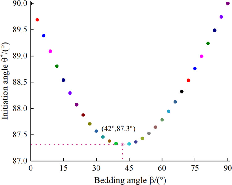
Relationship between initiation angle and bedding angle.
Figure 19.

Relationship between initiation pressure and bedding angle.
Comparing the experimental results with the theoretical solution, the variation law is the same; however, the value range is different. The theoretical solution of the fracture initiation pressure is in the range of 13.6–17.34 MPa, while the experimental results are in the range of 6.61–41.87 MPa. The reason is that there are natural fractures in the experimental shale sample, which leads to the phenomenon of stress concentration around the wellbore, resulting in a deviation between the theoretical solution and the experimental results. This shows that in future research, to accurately calculate the hydraulic fracturing of the shale, the randomly distributed natural fractures in the shale are one of the factors that must be considered.
6. Results and Discussion
The bedding plane in shale is well developed, and its existence leads to shale anisotropy. The bedding plane is an important factor that cannot be ignored in both on-site hydraulic fracturing construction and preliminary design. In this study, a hydraulic fracturing experiment on outcrop shale was conducted in a laboratory. The influence of the bedding angle on the initiation pressure, pump pressure curve, and hydraulic fracture shape was studied, and the interaction mode between hydraulic fractures and bedding plane was summarized. A new fracture initiation criterion was defined based on the anisotropy in the tensile strength of the shale, and the relationship between the initiation pressure and bedding angle was determined.
The sample selected in this study was outcrop shale. Generally, outcrop shale and shale reservoir have some differences, including in terms of the weathering degree, temperature, pore pressure, and original in situ stress. However, it is difficult to sample underground shale. Most drilling samples are cylindrical and small. When taken out from the ground, they are subjected to stress release, which affects their own properties. Hence, outcrop shale is a better choice. This study discussed experimental research on shale hydraulic fracturing. However, a laboratory experiment cannot fully simulate the characteristics of high temperature, high pressure, and high pore pressure of underground shale reservoirs, and there are significant size differences compared with shale reservoir. Therefore, the conclusions obtained cannot be directly applied in field construction. Nevertheless, some of the conclusions obtained from experiments can provide an important basis for understanding the influence of bedding plane on hydraulic fracturing and for optimizing field fracturing design.
Based on experimental pump pressure data, the pump pressure curve could be divided into four stages: continuous pressurization, internal pressure drop, internal pressure attenuation, and internal pressure equilibrium stages. Compared with field fracturing pump pressure data, it was found that the experimental data are consistent with small-scale field fracturing test pump pressure data, and there were some differences with large-scale field fracturing pump pressure data, which are embodied in two stages: internal pressure attenuation and internal pressure equilibrium stages. In the field pump pressure curve, the pressure attenuation stage is long, and there is no evident pressure balance stage. We believe that this is due to the size difference between laboratory shale sample and shale reservoir. The size of a laboratory shale sample is limited; therefore, fractures are easily formed throughout the sample during fracturing, resulting in fracturing fluid leakage; this is not the case in shale reservoirs. In addition, a shale reservoir contains a large number of natural fractures, which will also have some impact on the pump pressure.
In this study, some relationships between the bedding plane and fracture initiation pressure were obtained through laboratory hydraulic fracturing experiments. Compared with other studies, the conclusion that the initiation pressure at 0° is maximum and that at 90° is minimum is consistent. There are differences in the variation law for bedding angles ranging from 0 to 90°. The law obtained in this study is that the initiation pressure decreases gradually with the increase in the bedding angle. The laws reported in other studies are inconsistent. In some, the pressure increases first, decreases, and then increases; in others, it decreases first and then increases; and in some, no fixed law has been obtained.22,48,49 The factors affecting the experimental results mainly include the shale sample, in situ stress, and wellbore direction. First, the mechanical properties of shale samples from different regions are different. Second, with the increase in the in situ stress, the anisotropy of shale caused by bedding is weakened. Finally, drilling the wellbore in shale reservoirs will change the original structure of the shale sample. The above factors will affect the relationship between the bedding plane and the initiation pressure, which should be considered in future research.
7. Conclusions
-
(1)
The pressure curve at the bottom of the wellbore during shale hydraulic fracturing could be divided into four stages: continuous pressurization stage (it can be divided into front and back sections), internal pressure drop stage, internal pressure attenuation stage, and internal pressure equilibrium stage.
-
(2)
Combined with the pump pressure characteristics during fracturing, the evolution process of the hydraulic fractures could be divided into four processes: microfracture development process, fracture initiation process, fracture propagation process, and fracture network equilibrium process.
-
(3)
When the direction of the maximum principal stress is parallel to the bedding, a simple single fracture is easily formed, and when it is vertical, a complex fracture network is easily formed.
-
(4)
The interaction between the hydraulic fractures and the bedding plane could be divided into two categories: bedding face does not open or it opens. The interaction modes can be divided into eight types: Stopping after intersecting the bedding plane; crossing directly after intersecting the bedding plane; deflection crossing after intersecting bedding plane; opening the bedding surface and stopping after intersecting the bedding plane; opening the bedding plane and crossing directly after intersecting the bedding plane; opening the bedding plane and deflect crossing after intersecting the bedding plane; offset crossing after intersecting the bedding plane; offset and then deflect crossing after intersecting the bedding plane.
-
(5)
The existence of a bedding plane leads to anisotropy in the shale. Considering the anisotropy of the tensile strength, the initiation pressure and initiation angle of the shale hydraulic fracturing under different bedding angles were calculated. As the bedding angle increased, the initiation pressure decreased gradually and the initiation angle decreased first and then increased.
Acknowledgments
The authors gratefully acknowledge the financial support by the China National Science and Technology Major Project (grant no. 2017ZX05037001) and the Project of discipline innovation team of Liaoning Technical University (grant no. LNTU20TD-11).
The authors declare no competing financial interest.
References
- Gao S.; Dong D.; Tao K.; Guo W.; Li X.; Zhang S. Experiences and lessons learned from China’s shale gas development: 2005-2019. J. Nat. Gas Sci. Eng. 2021, 85, 103648 10.1016/j.jngse.2020.103648. [DOI] [Google Scholar]
- Li H.; Chang X. A review of the microseismic focal mechanism research. Sci. China Earth Sci. 2021, 64, 351–363. 10.1007/s11430-020-9658-7. [DOI] [Google Scholar]
- Soeder D. J. The successful development of gas and oil resources from shales in North America. J. Pet. Sci. Eng. 2018, 163, 399–420. 10.1016/j.petrol.2017.12.084. [DOI] [Google Scholar]
- Chen L.; Zhang G.; Lyu Y.; Li Z.; Zheng X. In Visualization Study of Hydraulic Fracture Propagation in Unconsolidated Sandstones, 53rd U.S. Rock Mechanics/Geomechanics Symposium, New York City, New York, 2019, ARMA-2019-1837.
- Ante M. A.; Manjunath G. L.; Aminzadeh F.; Jha B. In Microscale Laboratory Studies for Determining Fracture Directionality in Tight Sandstone and Shale During Hydraulic Fracturing, Proceedings of the 6th Unconventional Resources Technology Conference, 2018 10.15530/urtec-2018-2903021. [DOI]
- Gwaba D. C.; Germanovich L. N.; Hurt R. S.; Ayoub J.; Stanchits S. In Laboratory Study of Hydraulic Fracturing Behavior of Weakly-Consolidated Sediments Under True-Triaxial Stress Regimes, 53rd U.S. Rock Mechanics/Geomechanics Symposium, 2019, ARMA-2019-1760.
- Li Y.; Yang S.; Zhao W.; Li W.; Zhang J. Experimental of hydraulic fracture propagation using fixed-point multistage fracturing in a vertical well in tight sandstone reservoir. J. Pet. Sci. Eng. 2018, 171, 704–713. 10.1016/j.petrol.2018.07.080. [DOI] [Google Scholar]
- Abdelaziz A.; Ha J.; Khair H. A.; Adams M.; Tan C. P.; Musa I. H.; Grasselli G. In Unconventional Shale Hydraulic Fracturing Under True Triaxial Laboratory Conditions, the Value of Understanding Your Reservoir, SPE Annual Technical Conference and Exhibition, Calgary, Alberta, Canada, 2019, 10.2118/196026-MS. [DOI]
- Tomac I.; Sauter M. A review on challenges in the assessment of geomechanical rock performance for deep geothermal reservoir development. Renew. Sustainable Energy Rev. 2018, 82, 3972–3980. 10.1016/j.rser.2017.10.076. [DOI] [Google Scholar]
- Wu B.; Zhang G.; Zhang X.; Jeffrey R. G.; Kear J.; Zhao T. Semi-analytical model for a geothermal system considering the effect of areal flow between dipole wells on heat extraction. Energy 2017, 138, 290–305. 10.1016/j.energy.2017.07.043. [DOI] [Google Scholar]
- Zou Y.; Zhang S.; Ma X.; Zhou T.; Zeng B. Numerical investigation of hydraulic fracture network propagation in naturally fractured shale formations. J. Struct. Geol. 2016, 84, 1–13. 10.1016/j.jsg.2016.01.004. [DOI] [Google Scholar]
- Hubbert M. K.; Willis D. G. Mechanics Of Hydraulic Fracturing. Trans. AIME 1957, 210, 153–168. 10.2118/686-G. [DOI] [Google Scholar]
- Haimson B.; Fairhurst C. Hydraulic Fracturing in Porous-Permeable Materials. J. Pet. Technol. 1969, 21, 811–817. 10.2118/2354-PA. [DOI] [Google Scholar]
- Haimson B.; Fairhurst C. In In-situ Stress Determination at Great Depth by Means of Hydraulic Fracturing, 11th U.S. Symposium on Rock Mechanics (USRMS), 1969, ARMA-69-0559.
- Ito T.; Hayashi K. Physical background to the breakdown pressure in hydraulic fracturing tectonic stress measurements. Int. J. Rock Mech. Min. Sci. Geomech. Abs. 1991, 28, 285–293. 10.1016/0148-9062(91)90595-D. [DOI] [Google Scholar]
- Brenne S.; Molenda M.; Stöckhert F.; Alber M. In Hydraulic and Sleeve Fracturing Laboratory Experiments on 6 Rock Types, ISRM International Conference for Effective and Sustainable Hydraulic Fracturing, 2013.
- Cornetti P.; Pugno N.; Carpinteri A.; Taylor D. Finite fracture mechanics: A coupled stress and energy failure criterion. Eng. Fract. Mech. 2006, 73, 2021–2033. 10.1016/j.engfracmech.2006.03.010. [DOI] [Google Scholar]
- Schwartzkopff A. K.; Melkoumian N. S.; Xu C. Fracture mechanics approximation to predict the breakdown pressure using the theory of critical distances. Int. J. Rock Mech. Min. Sci. 2017, 95, 48–61. 10.1016/j.ijrmms.2017.03.006. [DOI] [Google Scholar]
- Zhang X.; Wang J.; Gao F.; Ju Y.; Liu J. Impact of water and nitrogen fracturing fluids on fracturing initiation pressure and flow pattern in anisotropic shale reservoirs. Comput. Geotech. 2017, 81, 59–76. 10.1016/j.compgeo.2016.07.011. [DOI] [Google Scholar]
- Leguillon D. Strength or toughness? A criterion for crack onset at a notch. Eur. J. Mech., A 2002, 21, 61–72. 10.1016/S0997-7538(01)01184-6. [DOI] [Google Scholar]
- Lecampion B. Modeling size effects associated with tensile fracture initiation from a wellbore. Int. J. Rock Mech. Min. Sci. 2012, 56, 67–76. 10.1016/j.ijrmms.2012.07.024. [DOI] [Google Scholar]
- Wang J.; Xie H.; Li C. Anisotropic failure behaviour and breakdown pressure interpretation of hydraulic fracturing experiments on shale. Int. J. Rock Mech. Min. Sci. 2021, 142, 104748 10.1016/j.ijrmms.2021.104748. [DOI] [Google Scholar]
- Qian Y.; Guo P.; Wang Y.; Zhao Y.; Lin H.; Liu Y. Advances in Laboratory-Scale Hydraulic Fracturing Experiments. Adv. Civ. Eng. 2020, 2020, 1386581 10.1155/2020/1386581. [DOI] [Google Scholar]
- Duan W.; Sun B.; Pan D.; Wang T.; Guo T.; Wang Z. Experimental study on fracture propagation of hydraulic fracturing for tight sandstone outcrop. Energy Explor. Exploit. 2021, 39, 156–179. 10.1177/0144598720972513. [DOI] [Google Scholar]
- Hayashi K.; Ito T. In situ stress measurement by hydraulic fracturing at the Kamaishi mine. Int. J. Rock Mech. Min. Sci. Geomech. Abs. 1993, 30, 951–957. 10.1016/0148-9062(93)90051-E. [DOI] [Google Scholar]
- Warpinski N. R.; Teufel L. W. Influence of Geologic Discontinuities on Hydraulic Fracture Propagation. J. Pet. Technol. 1987, 39, 209–220. 10.2118/13224-PA. [DOI] [Google Scholar]
- Beugelsdijk L. J. L.; De Pater C. J.; Sato K. In Experimental Hydraulic Fracture Propagation in a Multi-Fractured Medium,SPE Asia Pacific Conference on Integrated Modelling for Asset Management, 2000.
- Zhou J.; Jin Y.; Chen M. Experimental investigation of hydraulic fracturing in random naturally fractured blocks. Int. J. Rock Mech. Min. Sci. 2010, 47, 1193–1199. 10.1016/j.ijrmms.2010.07.005. [DOI] [Google Scholar]
- Lee H. P.; Olson J. E.; Holder J.; Gale J. F. W.; Myers R. D. The interaction of propagating opening mode fractures with preexisting discontinuities in shale. J. Geophys. Res.: Solid Earth 2015, 120, 169–181. 10.1002/2014JB011358. [DOI] [Google Scholar]
- Aydin A. Failure modes of shales and their implications for natural and man-made fracture assemblages. AAPG Bull. 2014, 98, 2391–2409. 10.1306/07311413112. [DOI] [Google Scholar]
- Blanton T. L. In An Experimental Study of Interaction Between Hydraulically Induced and Pre-Existing Fractures, SPE Unconventional Gas Recovery Symposium, Pittsburgh, Pennsylvania, 1982.
- Wang W.; Olson J. E.; Prodanović M.; Schultz R. A. Interaction between cemented natural fractures and hydraulic fractures assessed by experiments and numerical simulations. J. Pet. Sci. Eng. 2018, 167, 506–516. 10.1016/j.petrol.2018.03.095. [DOI] [Google Scholar]
- Kumari W. G. P.; Ranjith P. G.; Perera M. S. A.; Chen B. K.; Abdulagatov I. M. Temperature-dependent mechanical behaviour of Australian Strathbogie granite with different cooling treatments. Eng. Geol. 2017, 229, 31–44. 10.1016/j.enggeo.2017.09.012. [DOI] [Google Scholar]
- Kumari W. G. P.; Ranjith P. G.; Perera M. S. A.; Li X.; Li L. H.; Chen B. K.; Avanthi Isaka B. L.; De Silva V. R. S. Hydraulic fracturing under high temperature and pressure conditions with micro CT applications: Geothermal energy from hot dry rocks. Fuel 2018, 230, 138–154. 10.1016/j.fuel.2018.05.040. [DOI] [Google Scholar]
- Xing Y.; Zhang G.; Luo T.; Jiang Y.; Ning S. Hydraulic fracturing in high-temperature granite characterized by acoustic emission. J. Pet. Sci. Eng. 2019, 178, 475–484. 10.1016/j.petrol.2019.03.050. [DOI] [Google Scholar]
- Hou B.; Diao C.; Li D. An experimental investigation of geomechanical properties of deep tight gas reservoirs. J. Nat. Gas Sci. Eng. 2017, 47, 22–33. 10.1016/j.jngse.2017.09.004. [DOI] [Google Scholar]
- Kang P.; Hong L.; Yan F.; Zou Q.; Xiao S.; Liu Z. Effects of temperature on mechanical properties of granite under different fracture modes. Eng. Fract. Mech. 2020, 226, 106838 10.1016/j.engfracmech.2019.106838. [DOI] [Google Scholar]
- Akai T.; Yano S.; Kurosawa I.; Chen Y.; Ishida T. In Consideration on Shape of Hydraulic Fracture Based on Laboratory Experiment, Abu Dhabi International Petroleum Exhibition and Conference, Abu Dhabi, UAE, 2015.
- Guo T.; Zhang S.; Qu Z.; Zhou T.; Xiao Y.; Gao J. Experimental study of hydraulic fracturing for shale by stimulated reservoir volume. Fuel 2014, 128, 373–380. 10.1016/j.fuel.2014.03.029. [DOI] [Google Scholar]
- Zhou Z.-L.; Zhang G.; Dong H.; Liu Z.; Nie Y. Creating a network of hydraulic fractures by cyclic pumping. Int. J. Rock Mech. Min. Sci. 2017, 97, 52–63. 10.1016/j.ijrmms.2017.06.009. [DOI] [Google Scholar]
- Guo T.; Tang S.; Liu S.; Liu X.; Xu J.; Qi N.; Rui Z. Physical simulation of hydraulic fracturing of large-sized tight sandstone outcrops. SPE J. 2021, 26, 372–393. 10.2118/204210-PA. [DOI] [Google Scholar]
- Liu Q.; Liang B.; Sun W.; Zhao H. Experimental Study on the Difference of Shale Mechanical Properties. Adv. Civ. Eng. 2021, 2021, 6677992 10.1155/2021/6677992. [DOI] [Google Scholar]
- Li C.; Xie H.; Wang J. Anisotropic characteristics of crack initiation and crack damage thresholds for shale. Int. J. Rock Mech. Min. Sci. 2020, 126, 104178 10.1016/j.ijrmms.2019.104178. [DOI] [Google Scholar]
- Jin Z.; Li W.; Jin C.; Hambleton J.; Cusatis G. Anisotropic elastic, strength, and fracture properties of Marcellus shale. Int. J. Rock Mech. Min. Sci. 2018, 109, 124–137. 10.1016/j.ijrmms.2018.06.009. [DOI] [Google Scholar]
- Chalmers G. R.; Bustin R. M.; Power I. M. Characterization of gas shale pore systems by porosimetry, pycnometry, surfacearea, and field emission scanning electron microscopy/transmission electron microscopy image analyses: Examples from the Barnett, Woodford, Haynesville, Marcellus, and Doig units. AAPG Bull. 2012, 96, 1099–1119. [Google Scholar]
- Wang P.; Ren F.; Miao S.; Cai M.; Yang T. Evaluation of the anisotropy and directionality of a jointed rock mass under numerical direct shear tests. Eng. Geol. 2017, 225, 29–41. 10.1016/j.enggeo.2017.03.004. [DOI] [Google Scholar]
- Haimson B.; Fairhurst C. Initiation and Extension of Hydraulic Fractures in Rocks. Soc. Pet. Eng. J. 1967, 7, 310–318. 10.2118/1710-PA. [DOI] [Google Scholar]
- Lin C.; He J.; Li X.; Wan X.; Zheng B. An Experimental Investigation into the Effects of the Anisotropy of Shale on Hydraulic Fracture Propagation. Rock Mech. Rock Eng. 2017, 50, 543–554. 10.1007/s00603-016-1136-4. [DOI] [Google Scholar]
- Chun T.; Zhu D.; Zhang Z.; Mao S.; Wu K. Experimental Study of Proppant Transport in Complex Fractures with Horizontal Bedding Planes for Slickwater Fracturing. SPE Prod. Oper. 2021, 36, 83–96. 10.2118/199877-PA. [DOI] [Google Scholar]