

Abstract

Phased-array metasurfaces grant the ability to arbitrarily shape the wavefront of light. As such, they have been used as various optical elements including waveplates, lenses, and beam deflectors. Luminescent metasurfaces, on the other hand, have largely comprised uniform arrays and are therefore unable to provide the same control over the wavefront of emitted light. Recently, phased-array control of the wavefront of spontaneous emission has been experimentally demonstrated in luminescent phased-array metalenses and beam deflectors. However, current luminescent metasurface beam deflectors exhibit unidirectional emission for only p-polarized light. In this paper, we use a reciprocal simulation strategy to explain the polarization disparity and improve the directionality of incoherent emission from current quantum-well emitting phased-array metasurfaces. We also design complementary metasurfaces to direct emission from systems where emission originates from alternate quantum mechanical processes.
Introduction
Traditional phased-array metasurfaces grant control over the propagation of transmitted and reflected light by engineering the shape and size of their constituent meta-elements to impart a desired phase profile to a spatially coherent incident beam. Owing to their ability to arbitrarily shape the wavefront of coherent light, traditional phased-array metasurfaces have seen use as beam deflectors,1,2 polarizing elements,3,4 lenses,5−7 holographic phase masks,7−9 and vortex beam generators.10,11 In this sense, most traditional phased-array metasurfaces are optical elements, which require a coherent incident light source. Luminescent metasurfaces, on the other hand, are integrated with their own generally incoherent light source. Although early work coupling emitters to plasmonic nanoantenna showed luminescent phased functionality,12−15 much of the subsequent work has focused on metasurfaces with uniform arrays.16−21 Although uniform metasurfaces impact the spectrum, radiation patterns, and emission intensity of the coupled lumophore, they are unable to impart the phase control necessary for arbitrary wavefront shaping.
Recently, luminescent phased-array metasurface lenses, axicons, and beam deflectors comprising gallium nitride (GaN) nanopillars embedded with InGaN quantum wells (QWs) have been experimentally demonstrated.22,23 Because these luminescent phased-array metasurfaces are a relatively new outgrowth of the more traditional transmissive and reflective metasurfaces, many questions remain as to their operation and design. In particular, although the luminescent beam deflectors produced by Ilyer et al. exhibited both p- and s-polarized unidirectional transmission, unidirectional photoluminescence was observed for p-polarized but not s-polarized light.22 Further, although an accompanying analytical model accurately explained the most striking features of the emission patterns, it lacks the explanatory power to explain this polarization dependence andenable robust design of future luminescent metasurfaces for application in areal lighting, next-generation displays, and optical communications.
In this work, we validate the results of a reciprocity-based simulation scheme against experimentally measured momentum-resolved photoluminescence spectra. Subsequently, we employ these reciprocal simulations to predict the emission patterns of luminescent beam deflectors, identify important parameters for achieving directionality, and develop heuristics for metasurface design. These tools allow us to investigate the highly polarized nature of the directional emission seen in experiment. Lastly, we use the simulation tools and heuristics to improve the directionality of p-polarized emission by 60% over the previous work, design first-ever beam deflectors capable of highly directional s-polarized emission, design metasurfaces for directional air-side emission, and identify metasurface designs for directing emission from other quantum-well systems with different underlying quantum mechanical transitions. These results aid in our practical understanding of unidirectional emission from luminescent phased-array metasurfaces and allow the optimization of future devices.
Simulation Approach
In a beam-deflecting metasurface, a coherent plane wave with a
transverse momentum of k∥,i = k0 sin(θi) is redirected into a unidirectional transmission
lobe with a transverse momentum of k∥,t = k0 sin(θt),
where k0 is the free space momentum and
θi and θt are the
angles of incidence and transmission, respectively. The difference
between the momenta of the transmitted and incident waves is equal
to the “metasurface momentum”, kM = k∥,t – k∥,i. Assuming a linear
metasurface phase gradient, 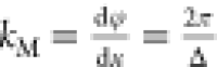 , where φ is the phase profile with
respect to position, x is the free space wavelength,
and Δ is the metasurface macroperiod. Using the above principles,
a beam-deflecting metasurface can achieve unidirectional transmission
according to
, where φ is the phase profile with
respect to position, x is the free space wavelength,
and Δ is the metasurface macroperiod. Using the above principles,
a beam-deflecting metasurface can achieve unidirectional transmission
according to 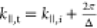 . This description breaks down when we consider
that spontaneous emission is generally spread across momentum space
and a well-defined input momentum cannot be ascribed to the emitted
light. However, the spontaneous emission from in-plane electric dipoles
in InGaN/GaN QW thin films has a strong distinct peak just beyond
the critical angle at k∥,i = ±1.06k0, as seen in Figure 1a. Although this
ray is ordinarily trapped in the substrate, metasurface patterning
can redirect the emission and facilitate extraction into air.
. This description breaks down when we consider
that spontaneous emission is generally spread across momentum space
and a well-defined input momentum cannot be ascribed to the emitted
light. However, the spontaneous emission from in-plane electric dipoles
in InGaN/GaN QW thin films has a strong distinct peak just beyond
the critical angle at k∥,i = ±1.06k0, as seen in Figure 1a. Although this
ray is ordinarily trapped in the substrate, metasurface patterning
can redirect the emission and facilitate extraction into air.
Figure 1.

(a) Momentum-resolved radiation pattern of InGaN QWs in an unpatterned GaN thin film. (b) Schematic representation of a beam deflector simulation. The yellow layer in the nanopillars represents the QW region, and the green arrow represents the input plane wave, which is then swept across momentum space.
To investigate the observed polarization dependence, find metasurface designs capable of directional s-polarized emission from in-plane electric dipoles, and investigate the directional emission from alternate quantum emitters, we employ and evaluate a reciprocity-based numerical simulation scheme.16,24,25 We simulate beam deflectors comprising arrays of square cross section, 1450 nm tall GaN nanopillars of varying widths with InGaN QWs embedded 113–148 nm below the air/GaN interface. Nanopillars are spaced 250 nm apart and sit atop a sapphire substrate. The nanopillar widths are chosen to give a linearly varying transmission phase, as discussed in our previous work.22,23 An angled plane wave is sourced within the semi-infinite sapphire substrate and propagates toward the metasurface (Figure 1b). The incident angle for both p- and s-polarized light is swept to predict the far-field emission pattern as a function of angle. By reciprocity, the integrated electric field component, ∫|Ei(x,y)|2dxdy, in the QW region is proportional to the emitted far-field photoluminescence intensity at the same angle from a dipole source oriented along i.26 Thus, we are able to quickly simulate p- or s-polarized emission from hypothetical QWs at any arbitrary position in the nanopillar with the same angle-dependent simulations by integrating the appropriate electric field component at the desired z coordinate. The reciprocal method also allows us to simulate a small periodic region of the metasurface as opposed to a large, finite array, as would be needed in a local dipole source method,27 giving us both smaller simulation domains and QW position multiplexing. Details of the simulation settings can be found in the Methods: Simulation Details section.
Results and Discussion
Figure 2 shows experimental (solid line) and simulated (circles) emission patterns of 540 nm light as a function of transverse momentum. Results are shown for both p- (left) and s-polarized (right) light for two different one-dimensional (1D) beam deflectors, one designed to emit at −0.41 k0 (top) and another at −0.08 k0 (bottom). Emission patterns from other 1D beam deflectors are given in Supporting Figure 1. Calculations and measurements agree very well for p-polarized emission—the simulations accurately predict the location and intensity of the main metasurface-mediated unidirectional emission lobes. Calculations and measurements also agree for s-polarized emission—predicting all of the major emission features, including the local minimum at the target emission momentum.
Figure 2.

Simulated (circles) and measured (lines) emission at 540 nm for (a) p-polarized and (b) s-polarized light from two beam deflectors designed to emit at either −0.41 k0 (top) or −0.08 k0 (bottom).
The variance seen for p- and s-polarized emission from these metasurfaces is dramatic. Whereas p-polarized emission shows a maximum at the target momentum, s-polarized emission shows a local minimum. To understand this polarization dependence, which is nearly absent in transmission,22 it is important to understand the fundamentally different mechanisms by which metasurfaces impart directionality to transmitted versus emitted light. In transmission, each nanopillar is “sourced” by an incident plane wave, which creates a defined phase relationship between the different nanopillars. As the light propagates down, each nanopillar imparts a different phase shift producing the desired output phase. In this abstraction, interpillar coupling—whereby source dipoles in one nanopillar generate induced polarization dipoles in neighboring nanopillars—produces a small perturbation of the desired results. If interpillar coupling is ignored, the fourfold nanopillar symmetry produces identical results for s- and p-polarization. In the case of luminescent metasurfaces, however, interpillar coupling is essential to achieving directional emission.
In luminescent operation, a single source dipole in one nanopillar induces polarization dipoles in neighboring nanopillars with a well-defined phase relationship. The interference between waves generated via source and induced dipoles leads to directional emission. The emission from varying source dipoles is summed incoherently, as necessitated in spontaneous emission. Thus, p-polarized emission—which is driven by dipoles oriented parallel to the phase gradient—will exhibit different interpillar coupling phases relative to s-polarized emission—which is driven by in-plane dipoles oriented perpendicular to the phase gradient. Figure 3 shows the phase of 540 nm light emitted from dipoles placed 120 nm below the air/GaN interface of a uniform array of 1450 nm tall, 170 nm wide nanopillars—other nanopillar widths show similar patterns. We see that p-polarized light accumulates approximately π radians of phase between neighboring nanopillars, whereas s-polarized light accumulates approximately 0.5 π radians of phase between the source dipole and an induced dipole. Details of this simulation can be found in the Methods: Simulation Details.
Figure 3.

Phase of light emitted from dipoles placed at the QW location of a uniform array of nanopillars—vertical line marks the center of the neighboring nanopillar.
Having first experimentally validated our numerical simulations, we subsequently use them to optimize the existing luminescent metasurface designs. In an effort to standardize and expedite our simulations, we chose to simulate luminescent beam deflectors comprised of 1000 nm tall nanopillars with metasurface momentum kM = 0.72 k0. Naturally, changing the nanopillar height necessitates recalculating the relationship between nanopillar width and phase response; see the Methods: Simulation Details section for details.
As
these reciprocal simulations allow for QW position multiplexing,
emission patterns of p-polarized light were simultaneously calculated
for QWs spanning from 0 to 400 nm below the GaN/air interface. The
emission pattern for 540 nm was extracted as described above, and
the directivity at the target angle (θt = 0.193 rad), 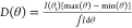 , was calculated as a function
of the normalized
QW position. Consistent with our previous experimental design intuition,
maximum directivity occurs for QWs placed nearly 0.5 λ0/n below the GaN/air interface. Specifically, we
see that maximum directivity occurs at 0.477 λ0/n (110 nm). Similar simulations were carried out using 480–560
nm incident light. These wavelengths roughly correspond to the InGaN
QW emission band (Figure 4a, inset). The directivity as a function of the QW position
for all source wavelengths is shown Figure 4a. We see a clear sinusoidal pattern for
each wavelength, and a marked increase in directivity as the source
wavelength decreases from 540 to 500 nm. A maximum directivity of D = 5.59 is seen with a 500 nm source for QWs placed 0.328
λ0/n (70 nm) below the air/GaN interface.
Since our simulations use nondispersive optical constants, this increase
in directivity is achievable for our design wavelength of 540 nm (the
wavelength of maximal emission for InGaN QWs) by scaling all metasurface
dimensions by 540/500. When we simulate a metasurface that accounts
for both QW position and the wavelength-based isotropic scaling, we
see that we can achieve a 60% increase in directionality over the
initial unscaled metasurface design where we place the QW 0.5 λ0/n (115 nm) below the air/GaN interface (see Figure 4b). We see that in
addition to QW position, moderate isotropic scaling can have a powerful
impact on directionality. Interestingly, this improved design represents
a 90% increase in directionality over the best metasurface produced
by Ilyer et al.22
, was calculated as a function
of the normalized
QW position. Consistent with our previous experimental design intuition,
maximum directivity occurs for QWs placed nearly 0.5 λ0/n below the GaN/air interface. Specifically, we
see that maximum directivity occurs at 0.477 λ0/n (110 nm). Similar simulations were carried out using 480–560
nm incident light. These wavelengths roughly correspond to the InGaN
QW emission band (Figure 4a, inset). The directivity as a function of the QW position
for all source wavelengths is shown Figure 4a. We see a clear sinusoidal pattern for
each wavelength, and a marked increase in directivity as the source
wavelength decreases from 540 to 500 nm. A maximum directivity of D = 5.59 is seen with a 500 nm source for QWs placed 0.328
λ0/n (70 nm) below the air/GaN interface.
Since our simulations use nondispersive optical constants, this increase
in directivity is achievable for our design wavelength of 540 nm (the
wavelength of maximal emission for InGaN QWs) by scaling all metasurface
dimensions by 540/500. When we simulate a metasurface that accounts
for both QW position and the wavelength-based isotropic scaling, we
see that we can achieve a 60% increase in directionality over the
initial unscaled metasurface design where we place the QW 0.5 λ0/n (115 nm) below the air/GaN interface (see Figure 4b). We see that in
addition to QW position, moderate isotropic scaling can have a powerful
impact on directionality. Interestingly, this improved design represents
a 90% increase in directionality over the best metasurface produced
by Ilyer et al.22
Figure 4.

(a) Simulated directivity of p-polarized emission as a function of QW position for a variety of wavelengths. The inset shows the emission spectrum of a luminescent metasurface peaking at 539.5 nm. (b) Simulated emission for p-polarized light from a beam deflector with a target momentum of 0.34 k0 at 540 nm before (blue) and after (red) QW relocation and dimension rescaling.
In addition to improving unidirectional p-polarized emission, we can use our simulation technique to identify metasurface designs for unidirectional s-polarized emission. Just as with p-polarized light, the directivity of s-polarized light has a sinusoidal relationship with the QW position. The s-polarization cycle is approximately 180° out of phase with the p-polarization cycle: the s-polarization maxima occur near p-polarization minima (Figure 5a). This is important in explaining the difference in directionality between p- and s-polarizations in experimental metasurfaces. The experimental metasurfaces had their QWs located at approximately 0.5 λ0/n. This QW location corresponds to sub-unity directionality, whereas high directivity occurs near 0.9 λ0/n. In an attempt to improve directionality, we again rescale to the initial metasurface design, as described above. We see that directivity is maximized (D = 2.48) at the original scale (540 nm) for a QW located 0.867 λ0/n (200 nm) below the air/GaN interface. The directional s-polarized emission pattern is shown in Figure 5b alongside the original emission pattern corresponding to QWs placed 120 nm below the air interface. (Note the similarities between the initial trace in Figure 5b and s-polarized traces in Figure 2b.) By appropriately relocating the QWs, undesired emission at high momenta is minimized, while emission at the target momentum transforms from a local minimum to a global maximum, as desired for unidirectional emission.
Figure 5.

(a) Simulated directivity of s-polarized emission as a function of QW position for a variety of wavelengths. (b) Simulated normalized emission for 540 nm s-polarized light from a beam deflector with a target momentum of 0.34 k0 at 540 nm before (blue) and after (red) relocating the QWs.
All simulations thus far have utilized a plane wave source originating within the substrate. This was originally done to compare simulation with experiment (Figure 2), but emission does not need to be collected from the substrate. We can easily simulate emission directly into air by sourcing the plane wave in air. Naturally, the QWs of an air-side emitter should be located near the sapphire/GaN interface, such that an appreciable transmission phase can accumulate through the nanopillar. Balancing this need for QW depth with growth defects caused by a lattice mismatch between sapphire and GaN, we performed a new phase-width calibration for QWs located about halfway up the nanopillars. As above, our air-side luminescent beam deflector is designed for a target output momentum kx = 0.34 k0. Running corresponding simulations for a variety of scaling factors and measuring directivity, we obtain Figure 6a. Although the directivity is not quite as high, the same sinusoidal pattern is seen here as in the case of substrate-side emission. Figure 6b shows the maximally directional emission, corresponding to a metasurface that has had its dimensions scaled by 540/530, its QW buried 2.74 λ0/n (560 nm) below the air/GaN interface, and a directivity of D = 2.47.
Figure 6.

(a) Simulated directivity of p-polarized emission as a function of QW position for a variety of wavelengths. (b) Simulated normalized emission for an air-side beam deflector with a target momentum of 0.34 k0.
Finally, we can use these simulations to move beyond in-plane electric dipoles characteristic of InGaN/GaN QWs. Specifically, we can investigate metasurface emission from out-of-plane electric dipoles by considering the out-of-plane electric field component from p-polarized sources in substrate-side simulations. Using the same design as for other substrate-side simulations, we see unidirectional emission at the target wavelength for out-of-plane electric dipoles located about 0.9 λ0/n below the air–GaN interface of the default structures (see Figure 7a). As above, we rescale the simulation to improve directionality. We see that a 540/510 isotropic scaling provides maximal directionality, D = 3.82, when the QW is placed 0.826 λ0/n (180 nm) below the air/GaN interface. Simulated emission results corresponding to the maximal directionality can be seen in Figure 7b.
Figure 7.

(a) Directivity of the simulated p-polarized emission from out-of-plane electric dipoles as a function of the emitter position for a variety of wavelengths. (b) Simulated normalized emission for p-polarized light from a beam deflector with a target momentum of 0.34 k0.
Conclusions
Luminescent phased-array metasurfaces grant the ability to shape the wavefront of spontaneous emission. However, owing to the lack of sophisticated modeling tools, questions of how to achieve unidirectional emission from the various types and orientations of quantum emitters were unanswerable. In this paper, we determine that the polarization-based disparity in emission from luminescent phased-array beam-deflecting metasurfaces is partially due to the difference in the phase of induced dipoles from disparately oriented source dipoles. We employ a powerful simulation strategy to predict the momentum-resolved emission patterns from luminescent metasurfaces and identify the importance of QW position in ensuring directional emission. We also see that minor isotropic scaling can result in the marked improvement of directionality. We have designed new luminescent beam-deflecting metasurfaces with highly directional p- and s-polarized emission from in-plane electric dipoles. We similarly designed metasurfaces capable of directional air-side emission. And finally, we design metasurfaces capable of directional substrate-side p-polarized emission from out-of-plane electric dipoles. The simulation tools and heuristics developed here will dramatically improve the design and efficiency of luminescent beam deflectors and provide a launching point for the further exploration of luminescent phased-array metasurfaces.
Methods: Simulation Details
Lumerical FDTD was used for all simulations.
Nanopillar Phase-Width Calculations
A unit cell consisting of a nanopillar atop a sapphire substrate was illuminated by a 540 nm dipole placed 100 nm below the top of the nanopillar. Bloch boundary conditions were used in the lateral planes, and perfectly matched layers were used above and below the nanopillar. The phase of the transmitted electric field was measured one wavelength below the nanopillar. The nanopillar width was altered in subsequent simulations to obtain a phase-width response, as seen in Figure S2.
Metasurface Emission Simulations
The desired metasurface was constructed as described in the text. Bloch boundary conditions were used along the lateral planes, while perfectly matched layers were used above and below the metasurface. An auto nonuniform mesh type 24-layer steep angle perfectly matched layer (PML) boundary was used. An additional override mesh with a 13 nm resolution was used throughout the hypothetical QW region. The electric field intensity at the QW was determined via a frequency domain power monitor.
Dipole Phase Simulations
A 7 × 7 array of nanopillars, with dimensions as indicated in the text, on sapphire was simulated with PML boundaries on all sides. A 540 nm dipole source was placed at the QW location, and an additional override mesh was placed near the source dipole to increase resolution. The phase of emitted light was measured across the plane of the QW using a frequency domain power monitor.
Acknowledgments
This work was supported by the Office of Naval Research (Grant #N00014–22–1–2337). Partial support was obtained from the Solid State Lighting and Energy Electronics Center. Use was made of computational facilities purchased with funds from the National Science Foundation (CNS-1725797) and administered by the Center for Scientific Computing (CSC). The CSC was supported by the California NanoSystems Institute and the Materials Research Science and Engineering Center (MRSEC; NSF DMR 1720256) at UC Santa Barbara.
Supporting Information Available
The Supporting Information is available free of charge at https://pubs.acs.org/doi/10.1021/acsomega.2c01654.
Additional validation of simulation results and details concerning the calculation of the phase profiles used in this work (PDF)
The authors declare no competing financial interest.
Supplementary Material
References
- Yu N.; Genevet P.; Kats M. A.; Aieta F.; Tetienne J.-P.; Capasso F.; Gaburro Z. Light Propagation with Phase Discontinuities: Generalized Laws of Reflection and Refraction. Science 2011, 334, 333–337. 10.1126/science.1210713. [DOI] [PubMed] [Google Scholar]
- Yu N.; Capasso F. Flat Optics with Designer Metasurfaces. Nat. Mater. 2014, 13, 139–150. 10.1038/nmat3839. [DOI] [PubMed] [Google Scholar]
- Arbabi A.; Horie Y.; Bagheri M.; Faraon A. Dielectric Metasurfaces for Complete Control of Phase and Polarization with Subwavelength Spatial Resolution and High Transmission. Nat. Nanotechol. 2015, 10, 937–943. 10.1038/nnano.2015.186. [DOI] [PubMed] [Google Scholar]
- Khorasaninejad M.; Zhu W.; Crozier K. B. Efficient Polarization Beam Splitter Pixels Based on a Dielectric Metasurface. Optica 2015, 2, 376–382. 10.1364/OPTICA.2.000376. [DOI] [Google Scholar]
- Chen W. T.; Zhu A. Y.; Sanjeev V.; Khorasaninejad M.; Shi Z.; Lee E.; Capasso F. A Broadband Achromatic Metalens for Focusing and Imaging in the Visible. Nat. Nanotechnol. 2018, 13, 220–226. 10.1038/s41565-017-0034-6. [DOI] [PubMed] [Google Scholar]
- Khorasaninejad M.; Chen W. T.; Devlin R. C.; Oh J.; Zhu A. Y.; Capasso F. Metalenses at Visible Wavelengths: Diffraction-Limited Focusing and Subwavelength Resolution Imaging. Science 2016, 352, 1190–1194. 10.1126/science.aaf6644. [DOI] [PubMed] [Google Scholar]
- Liu M.; Zhu W.; Huo P.; Feng L.; Song M.; Zhang C.; Chen L.; Lezec H. J.; Lu Y.; Agrawal A.; Xu T. Multifunctional Metasurfaces Enabled by Simultaneous and Independent Control of Phase and Amplitude for Orthogonal Polarization States. Light: Sci. Appl. 2021, 10, 107 10.1038/s41377-021-00552-3. [DOI] [PMC free article] [PubMed] [Google Scholar]
- Ni X.; Kildishev A. V.; Shalaev V. M. Metasurface Holograms for Visible Light. Nat. Commun. 2013, 4, 2807 10.1038/ncomms3807. [DOI] [Google Scholar]
- Zheng G.; Mühlenbernd H.; Kenney M.; Li G.; Zentgraf T.; Zhang S. Metasurface Holograms Reaching 80% Efficiency. Nat. Nanotechol. 2015, 10, 308–312. 10.1038/nnano.2015.2. [DOI] [PubMed] [Google Scholar]
- Devlin R. C.; Ambrosio A.; Rubin N. A.; Mueller J. P. B.; Capasso F. Arbitrary Spin-to–Orbital Angular Momentum Conversion of Light. Science 2017, 358, 896–901. 10.1126/science.aao5392. [DOI] [PubMed] [Google Scholar]
- Liu M.; Huo P.; Zhu W.; Zhang C.; Zhang S.; Song M.; Zhang S.; Zhou Q.; Chen L.; Lezec H. J.; Agrawal A.; Lu Y.; Xu T. Broadband Generation of Perfect Poincaré Beams via Dielectric Spin-Multiplexed Metasurface. Nat. Commun. 2021, 12, 2230 10.1038/s41467-021-22462-z. [DOI] [PMC free article] [PubMed] [Google Scholar]
- Curto A. G.; Volpe G.; Taminiau T. H.; Kreuzer M. P.; Quidant R.; van Hulst N. F. Unidirectional Emission of a Quantum Dot Coupled to a Nanoantenna. Science 2010, 329, 930–933. 10.1126/science.1191922. [DOI] [PubMed] [Google Scholar]
- Kosako T.; Kadoya Y.; Hofmann H. F. Directional Control of Light by a Nano-Optical Yagi–Uda Antenna. Nat. Photonics 2010, 4, 312–315. 10.1038/nphoton.2010.34. [DOI] [Google Scholar]
- Langguth L.; Schokker A. H.; Guo K.; Koenderink A. F. Plasmonic Phase-Gradient Metasurface for Spontaneous Emission Control. Phys. Rev. B 2015, 92, 205401 10.1103/PhysRevB.92.205401. [DOI] [Google Scholar]
- Hancu I. M.; Curto A. G.; Castro-López M.; Kuttge M.; van Hulst N. F. Multipolar Interference for Directed Light Emission. Nano Lett. 2014, 14, 166–171. 10.1021/nl403681g. [DOI] [PubMed] [Google Scholar]
- Liu S.; Vaskin A.; Addamane S.; Leung B.; Tsai M.-C.; Yang Y.; Vabishchevich P. P.; Keeler G. A.; Wang G.; He X.; Kim Y.; Hartmann N. F.; Htoon H.; Doorn S. K.; Zilk M.; Pertsch T.; Balakrishnan G.; Sinclair M. B.; Staude I.; Brener I. Light-Emitting Metasurfaces: Simultaneous Control of Spontaneous Emission and Far-Field Radiation. Nano Lett. 2018, 18, 6906–6914. 10.1021/acs.nanolett.8b02808. [DOI] [PubMed] [Google Scholar]
- Vaskin A.; Liu S.; Addamane S.; Vabishchevich P. P.; Yang Y.; Balarishnan G.; Sinclair M. B.; Pertsch T.; Brener I.; Staude I. Manipulation of Quantum Dot Emission with Semiconductor Metasurfaces Exhibiting Magnetic Quadrupole Resonances. Opt. Express 2021, 29, 5567–5579. 10.1364/OE.414011. [DOI] [PubMed] [Google Scholar]
- Vaskin A.; Bohn J.; Chong K. E.; Bucher T.; Zilk M.; Choi D.-Y.; Neshev D. N.; Kivshar Y. S.; Pertsch T.; Staude I. Directional and Spectral Shaping of Light Emission with Mie-Resonant Silicon Nanoantenna Arrays. ACS Photonics 2018, 5, 1359–1364. 10.1021/acsphotonics.7b01375. [DOI] [Google Scholar]
- Luo S.; Li Q.; Yang Y.; Chen X.; Wang W.; Qu Y.; Qiu M. Controlling Fluorescence Emission with Split-Ring-Resonator-Based Plasmonic Metasurfaces. Laser Photonics Rev. 2017, 11, 1600299 10.1002/lpor.201600299. [DOI] [Google Scholar]
- Laux F.; Bonod N.; Gérard D. Single Emitter Fluorescence Enhancement with Surface Lattice Resonances. J. Phys. Chem. C 2017, 121, 13280–13289. 10.1021/acs.jpcc.7b04207. [DOI] [Google Scholar]
- Bucher T.; Vaskin A.; Mupparapu R.; Löchner F. J. F.; George A.; Chong K. E.; Fasold S.; Neumann C.; Choi D.-Y.; Eilenberger F.; Setzpfandt F.; Kivshar Y. S.; Pertsch T.; Turchanin A.; Staude I. Tailoring Photoluminescence from MoS2 Monolayers by Mie-Resonant Metasurfaces. ACS Photonics 2019, 6, 1002–1009. 10.1021/acsphotonics.8b01771. [DOI] [Google Scholar]
- Iyer P. P.; DeCrescent R. A.; Mohtashami Y.; Lheureux G.; Butakov N. A.; Alhassan A.; Weisbuch C.; Nakamura S.; DenBaars S. P.; Schuller J. A. Unidirectional Luminescence from InGaN/GaN Quantum-Well Metasurfaces. Nat. Photonics 2020, 14, 543–548. 10.1038/s41566-020-0641-x. [DOI] [Google Scholar]
- Mohtashami Y.; DeCrescent R. A.; Heki L. K.; Iyer P. P.; Butakov N. A.; Wong M. S.; Alhassan A.; Mitchell W. J.; Nakamura S.; DenBaars S. P.; Schuller J. A. Light-Emitting Metalenses and Meta-Axicons for Focusing and Beaming of Spontaneous Emission. Nat. Commun. 2021, 12, 3591 10.1038/s41467-021-23433-0. [DOI] [PMC free article] [PubMed] [Google Scholar]
- Zhang S.; Martins E. R.; Diyaf A. G.; Wilson J. I. B.; Turnbull G. A.; Samuel I. D. W. Calculation of the Emission Power Distribution of Microstructured OLEDs Using the Reciprocity Theorem. Synth. Met. 2015, 205, 127–133. 10.1016/j.synthmet.2015.03.035. [DOI] [Google Scholar]
- Wang X.; Li Y.; Toufanian R.; Kogos L. C.; Dennis A. M.; Paiella R. Geometrically Tunable Beamed Light Emission from a Quantum-Dot Ensemble Near a Gradient Metasurface. Adv. Opt. Mater. 2020, 8, 1901951 10.1002/adom.201901951. [DOI] [Google Scholar]
- Rau U. Superposition and Reciprocity in the Electroluminescence and Photoluminescence of Solar Cells. IEEE J. Photovoltaics 2012, 2, 169–172. 10.1109/JPHOTOV.2011.2179018. [DOI] [Google Scholar]
- Vaskin A.; Kolkowski R.; Koenderink A. F.; Staude I. Light-Emitting Metasurfaces. Nanophotonics 2019, 8, 1151–1198. 10.1515/nanoph-2019-0110. [DOI] [Google Scholar]
Associated Data
This section collects any data citations, data availability statements, or supplementary materials included in this article.