

Abstract
Background
The INGEVITY lead (Boston Scientific, St Paul, MN, USA) has excellent clinical performance. However, its single filar design results in decreased lead tensile strength and a possible challenging extraction. This study's goal is to evaluate techniques for extracting the INGEVITY lead.
Methods
Two‐ and three‐dimensional models were created to simulate lead extraction from a right atrial appendage lead implant with a left subclavian approach and lead/fibrosis attachment sites. Standard and unique lead extraction preparation strategies were evaluated. Traction forces were measured from a superior approach alone or in combination with a femoral approach.
Results
For lead extraction via the superior approach, leaving the terminal on the lead was the only factor influencing maximum tolerated load (p‐value = .0007). Scar attachment provided greater lead tensile strength by transferring traction loading forces to the polyurethane outer insulation but dependent on insulation integrity. The strongest extraction rail was seen with a simulated femoral snaring of a locking stylet within the INGEVITY lead. Deployed screw retraction was most successful by rotating a Philips LLD#2 stylet (Philips Healthcare, Amsterdam, Netherlands) within the lead.
Conclusion
Results from in vitro simulations of INGEVITY lead extraction from an atrial location found the lead has low maximum tensile strength resulting in a poor extraction rail with common extraction tools and methods. However, the strength of the INGEVITY Lead extraction rail can be significantly increased by leaving the lead terminal intact and femoral snaring of the locking stylet within the lead. Such techniques may improve extraction of the INGEVITY lead.
Keywords: extraction, femoral snare, INGEVITY lead, tensile strength
1. INTRODUCTION
Cardiac implantable electronic devices (CIED) continue to be implanted with an estimated yearly rate of 1.2 to 1.4 million devices worldwide including over 500,000 per year in the EU. 1 Unfortunately, some of these devices and/or their leads must later be extracted because of infection, vascular occlusion, lead malfunction, and to avoid lead redundancy. 1 , 2 Fundamental to extraction is using the implanted lead as a rail for the extraction tool which results in tension on the lead. Myocardial lead fixation, vascular fibrosis, and a patient's individual anatomy may amplify those stresses. The lead's ability to tolerate such stress depends on its tensile strength and potential traction points of failure such as weld joints, this is universally true of all leads.
In addition, leads must survive the hostile biological environment while enduring repetitive mechanical stress with millions of cardiac cycles each year. 1 , 3 New technology is introduced into the field to meet defined medical needs. The INGEVITY lead was approved by FDA on April 25, 2016 for use in a Boston Scientific MR Conditional System.
To date 874,000 INGEVITY leads have been implanted worldwide. Lead performance has observed 99.1% survival at 8 years for the 362,000 implanted leads in the United States (www.bostonscientific.com/en‐US/pprc/product‐performance‐report.html, accessed December 11, 2020).
The unique construction of the INGEVITY lead has been previously described. 4 Both the inner and outer conductor coils are a single filar of MP35N wire. This design minimizes the electrical coupling during an MRI in order to reduce potential heating of the tip; however it also reduces the axial strength of the lead when used as a rail for extraction.
The single filar conductor design presents the challenge when the INGEVITY lead is adhered by scar to intravascular structures or other leads. Once a stylet is locked within the lumen, the single filar coil easily stretches and uncoils leading to substantial stretching of the insulation, and ultimately delamination and fracture. This combination results in the loss of a stable extraction rail and potential inability to safely and successfully deploy extraction tools. Additionally, this unifilar inner coil results in a lower allowed torsional strength to retract a deployed helix. In this study, a dedicated in vitro testing evaluation of INGEVITY lead mechanical integrity during varying extraction maneuvers was performed. The study's purpose is to define the challenges present and provide potential solutions to aid the operator in extracting INGEVITY leads.
2. METHODS
Extraction techniques were evaluated including helix retraction, lead preparation, traction on the lead from a superior, pectoral location, and providing countertraction using a femoral snare technique. A right atrial transvenous lead pathway was simulated with a bench model (Appendix A). A three‐dimensional silicone heart model set‐up allowed helix retraction turn counts and a simplified two‐dimensional heart model set‐up allowed traction force measurement. Both models simulated an implant in the right atrial appendage via left subclavian approach (Figure 1). Lead extraction preparation strategies and simulated lead/scar attachment sites were evaluated. All leads underwent a minimum 7‐day soak in 37⁰C saline solution to simulate in vivo polymer and adhesive softening. 5
FIGURE 1.

Lead extraction test method set‐up. Picture of the Instron load frame used for lead extraction testing. Critical bending of a right atrial lead implant with a superior vena cava/innominate structure adhesion is demonstrated [Color figure can be viewed at wileyonlinelibrary.com]
2.1. Helix retraction
This portion of the study was created to evaluate the use of a various locking and non‐locking stylets to aid in helix retraction. The INGEVITY lead was placed into an anatomical pathway simulated by a three‐dimensional silicone heart model (Figure A1) submerged in a heated bath at 37°C.
In the simulated anatomical pathway with the lead tip in the right atrium and a fully extended helix, lead pathway tortuosity was added to challenge the lead extension/retraction mechanism. First a sharp bend on the lead at the junction between the subclavian and brachiocephalic veins; and in some test scenarios, an additional U‐shaped bend was added to the proximal lead end. Helix retraction attempts were conducted using various locking and non‐locking stylet types, with and without the proximal bend.
For each test, lead samples were prepared by removing the lead terminal pin and exposing the proximal 2.5 cm of inner coil. Locking and non‐locking stylets were inserted and, if applicable, locked within the lead with a fully extended helix. A hemostat was tightly clamped over the lead inner coil and stylet. Using the hemostat, the lead coil and stylet were turned counterclockwise in unison. Rotations were counted until the lead helix had fully retracted.
2.2. Lead extraction
Testing was completed using methods to simulate three unique anatomical attachment sites and extraction approaches. The first evaluated an extraction from a superior approach with only attachment at the myocardial lead tip. The second simulated a superior extraction approach as well when a portion of the lead body is attached to the SVC (Superior Vena Cava)/Innominate in addition to lead tip attachment. And finally, a condition with a combined superior‐inferior approach with two sites of attachment (SVC/innominate and snare). Countertraction is applied to the tip of the lead using a snare from an inferior/femoral approach. See Appendix A for further details.
Using the two‐dimensional test set‐up shown in Figure 1, the displacement (distance traveled) of lead components and load (force applied) to the INGEVITY lead during extraction was measured with an Instron Universal Testing System (Instron, Norwood, MA, USA).
To perform the experiment, the distal end of the lead was clamped to prevent movement, simulating adhesion to the myocardium or attachment to the snare. On the proximal end of the lead the locking stylet and/or suture were clamped together into the load cell to pull equally during the simulated extraction. Low friction pulleys were used to guide the lead through the anatomical model. The proximal end of the lead was pulled at a constant rate, 25.4 cm/min, until catastrophic lead failure. With each component failure the location was identified by video monitoring and corresponding load recorded.
Several lead preparation methods were used to complete the designed experiment as described in Table 1 and Table 2. Further description in Appendix A.
TABLE 1.
Lead preparation variables for experiments with a typical superior access lead extraction
| Typical lead extraction procedure (no femoral work station) | |
|---|---|
| Lead preparation input variables | Conditions |
|
Lead terminal |
|
| Locking stylets |
|
| Suture ligature to the lead body |
|
| Lead binding mechanism |
|
TABLE 2.
Lead preparation variables for experiments with a superior access lead extraction and femoral work station
| Lead extraction procedure including femoral work station | |
|---|---|
| Lead preparation input variables | Conditions |
| Locking stylets |
|
| Location of snare attachment (for counter‐traction rail support, still using a subclavian extraction method) |
|
| Femoral catheter used |
|
3. STATISTICS
Due to the complex level of interactions that occur during a lead extraction, along with binary aspects such as whether the lead terminal is removed, a Design of Experiment (DOE) methodology was used to vary preparation strategies and measure the resultant lead strength in simulated lead extraction. Combinations of each lead preparation variable were performed (Tables 1 and 2). DOE allows for the simultaneous study of the effects that several factors may have on a process, simultaneously allows for the study of interactions between the factors and is more efficient in terms of time and cost than varying a single factor at a time. 6
A full factorial designed experiment was used to assess all combinations of input variables within the Tip Only Attachment Method in a designed experiment with the primary response of maximum load. Additional runs were added to investigate additional observations such as PU degradation and influence of SVC Scar attachment. The design model was created by eliminating terms with statistical significance p‐value > .05. The full model contained all main effects and two factor interactions.
4. RESULTS
4.1. Helix retraction testing
The INGEVITY single filar design provided limited torque transfer down the coil to retract a deployed screw simulating a chronically implanted lead. Retracting the helix under nominal conditions (no proximal bend applied) required 37, 23, 39, and 6 counterclockwise turns when using the prepackaged stylet, no stylet, deployed Liberator (Cook Medical, Bloomington, IN, USA), and deployed LLD#2 (Philips Healthcare, Amsterdam, Netherlands), respectively. During challenge conditions, the helix could not be retracted after 40 turns for the prepackaged stylet or when using no stylet as shown in Figure 2. The LLD#2 was able to successfully retract the helix in the challenge test condition but required 17 turns. The Liberator stylet was not challenge tested because of its high turn count in the nominal test.
FIGURE 2.

Helix retraction turn count testing results. Test results for helix retraction turn count testing by stylet type and test condition [Color figure can be viewed at wileyonlinelibrary.com]
4.2. Lead extraction testing
4.2.1. Tip only attachment
To describe the force applied to the lead during this testing, Figure 3 provides a typical INGEVITY extendable/retractable lead test with a Cook Liberator lead locking stylet in place (Cook One‐tie and Suture used) undergoing traction. Critical is understanding which lead components bear the traction load and at what force the lead components fail. In Figure 3, at the start of the pull the ETFE (ethylene tetrafluoroethylene) insulation pulls away from the lead's distal coupler at approximately 2.5 lb (1.13 kg) and the flexible neck then breaks at approximately 3.5 lb (1.59 kg), corresponding to the maximum load observed during the simulated extraction. After which, the load reduces substantially as the single filar inner coil bears the brunt of traction forces and begins to stretch, unwind, and become “un‐locked” from the locking stylet distal end. After stretching and unwinding the inner coil fails at approximately 2.25 lb (1.02 kg).
FIGURE 3.

Example test result. Example of results from tensile test to failure for “attached only at the tip” test scenario (INGEVITY 52 cm lead, Cook Liberator locking stylet, terminal cut off of lead, suture and Cook One‐Tie used). (A) Shows drawing of INGEVITY lead tip after load has been applied causing the inner components to stretch and fracture. (B) Shows the force versus displacement curve with labels of various component failures during the test [Color figure can be viewed at wileyonlinelibrary.com]
Maximum forces for various test conditions are shown in Table 3 and Table 4. The only statistically significant factor found influencing maximum load was leaving the terminal pin on the lead (p‐value = .0007). A trend to increased strength was observed if the Cook One‐Tie (Cook Medical, Bloomington, IN, USA) was used with a Liberator stylet; however this was not present with the LLD#2 stylet. The influence of locking stylet type and the suture material used resulted in no statistically significant influence (increase or decrease) to the maximum load of the lead/extraction system.
TABLE 3.
Results from traction testing using a superior approach (left subclavian)
| Test run | Adhesion in the SVC | Traction approach | Lead terminal | Locking stylet | Suture used | Lead binding | PU damage | Maximum load (lb) |
|---|---|---|---|---|---|---|---|---|
| A | NO | Superior | Removed | LLD | NONE | One‐Tie | NO | 3.49 |
| B | NO | Superior | Removed | Liberator | Fiberwire | One‐Tie | NO | 3.44 |
| C | NO | Superior | Intact | Liberator | NONE | None | NO | 4.56 |
| D | NO | Superior | Intact | Liberator | Fiberwire | One‐Tie | NO | 5.73 |
| E | NO | Superior | Removed | Liberator | NONE | None | NO | 2.94 |
| F | NO | Superior | Removed | None | NONE | One‐Tie | NO | 4.7 |
| G | NO | Superior | Removed | None | Fiberwire | None | NO | 3.58 |
| H | NO | Superior | Removed | LLD | Fiberwire | None | NO | 3.71 |
| I | NO | Superior | Intact | None | Fiberwire | One‐Tie | NO | 3.02 |
| J | NO | Superior | Intact | LLD | NONE | One‐Tie | NO | 3.39 |
| K | NO | Superior | Intact | LLD | Fiberwire | None | NO | 3.86 |
| L | NO | Superior | Removed | LLD | Fiberwire | One‐Tie | NO | 3.26 |
| M | NO | Superior | Intact | LLD | Fiberwire | One‐Tie | NO | 3.97 |
| N | NO | Superior | Intact | Liberator | Fiberwire | None | NO | 4.16 |
| O | NO | Superior | Intact | Liberator | NONE | One‐Tie | NO | 3.85 |
| P | NO | Superior | Removed | Liberator | NONE | One‐Tie | NO | 3.63 |
| Q | NO | Superior | Removed | Liberator | Fiberwire | None | NO | 3.48 |
| R | NO | Superior | Intact | Liberator | Fiberwire | One‐Tie | NO | 3.97 |
| S | NO | Superior | Intact | Liberator | Fiberwire | One‐Tie | NO | 3.66 |
| T | NO | Superior | Intact | Liberator | Fiberwire | One‐Tie | NO | 6.06 |
| U | NO | Superior | Removed | LLD | NONE | None | NO | 2.77 |
| V | NO | Superior | Intact | LLD | NONE | None | NO | 5.04 |
| W | NO | Superior | Intact | LLD | NONE | None | NO | 4.85 |
| X | NO | Superior | Intact | LLD | Fiberwire | None | NO | 3.67 |
| Y | NO | Superior | Intact | LLD | Fiberwire | None | NO | 4.98 |
| Z | NO | Superior | Removed | LLD | Fiberwire | None | NO | 3.56 |
| AA | YES | Superior | Intact | Liberator | Fiberwire | None | NO | 8.23 |
| AB | YES | Superior | Removed | LLD | Fiberwire | None | NO | 8.24 |
| AC | YES | Superior | Intact | LLD | Fiberwire | None | NO | 6.86 |
| AD | YES | Superior | Removed | Liberator | Fiberwire | None | NO | 8.32 |
| AE | YES | Superior | Intact | LLD | None | None | NO | 7.14 |
| AF | YES | Superior | Intact | Liberator | Fiberwire | One‐Tie | NO | 9.43 |
| AG | YES | Superior | Intact | Liberator | Fiberwire | One‐Tie | NO | 7.72 |
| AH | YES | Superior | Intact | Liberator | Fiberwire | One‐Tie | YES | 5.04 |
| AI | YES | Superior | Intact | LLD | Fiberwire | None | YES | 4.49 |
TABLE 4.
Results from traction testing using an inferior approach
| Test run | Adhesion in the SVC | Traction approach | Snare attachment proximal to anode ring | Locking stylet | Suture used | Lead binding | Maximum load (lbf) |
|---|---|---|---|---|---|---|---|
| A | NO | Superior | 2.54 cm | Liberator | Fiberwire | One‐Tie | 8.26 |
| B | NO | Superior | 5.08 cm | Liberator | Fiberwire | One‐Tie | 6.89 |
| C | NO | Superior | 2.54 cm | LLD | Fiberwire | None | 6.63 |
| D | NO | Superior | 5.08 cm | LLD | Fiberwire | None | 13.05 |
| E | NO | Superior | 5.08 cm | Liberator | Fiberwire | One‐Tie | 16.22 |
| F | NO | Superior | 1.27 cm | Liberator | Fiberwire | One‐Tie | 6.25 |
| G | NO | Superior | 1.27 cm | LLD | Fiberwire | None | 7.65 |
| H | YES | Superior | 2.54 cm | Liberator | Fiberwire | One‐Tie | 8.42 |
| I | YES | Superior | 5.08 cm | Liberator | Fiberwire | One‐Tie | 15.22 |
| J | YES | Superior | 2.54 cm | LLD | Fiberwire | None | 13.59 |
| K | YES | Superior | 5.08 cm | LLD | Fiberwire | None | 10.25 |
In one test case the terminal boot broke during testing when the terminal was left intact and no suture material was used. This suggests a suture ligature on the proximal lead insulation may maintain control of the lead insulation under challenging circumstances.
4.2.2. Tip + SVC (superior vena cava)/innominate scar attachment
The mechanism of lead loading was substantially different in tests simulating a lead with SVC/Innominate tissue attachment, as shown in Figure 4. Attachment in the level of the SVC/Innominate vein resulted in initial loading on the polyurethane outer insulation providing a stronger support followed by loading of the inner coil once the polyurethane body failed. However, the maximum force was highly dependent on insulation integrity, as a nick or tear quickly propagated to a full breach, as shown with the red line in Figure 4. The maximum load achieved when the polyurethane outer insulation was in pristine condition was ∼8 lb (3.63 kg) compared to only ∼4.8 lb (2.18 kg) when compromised by a small cut/nick in the insulation (p‐value = .025).
FIGURE 4.

Comparison of damaged and nondamaged Polyurethane Body Tubing in SVC/innominate scar and tip attachment model. Load versus Extension plots of test cases with scar attachment at the lead tip and within the Superior Vena Cava/Innominate structures. The Black line includes data for a sample without damage to the polyurethane body tubing. The red dotted line includes data for a sample with damage to the polyurethane body tubing illustrating early PU failure and subsequent inner coil failure [Color figure can be viewed at wileyonlinelibrary.com]
There was no statistically significant influence of the terminal condition (cut off or intact) or type of locking stylet used as it related to the maximum load the lead/extraction system was able to achieve.
4.2.3. Combined superior‐inferior approach
The combined superior‐inferior approach provided a strong rail when the snare was able to engage a section of the lead with a locking stylet locked within.
An example of high tensile strength and low elongation using this technique is shown in Figure 5; a typical INGEVITY lead test with a Philips LLD EZ lead locking stylet in place (Suture is used, One‐Tie is not used) undergoing traction with a Needle's Eye Snare (Cook Medical, IN, USA, Model G26517) through the provided sheath attached ∼5 cm proximal to the lead's anode. The Needle's Eye system provided includes both and inner and outer sheath. The lead was prolapsed into the inner sheath ∼1.5 cm. At the start of the pull the force of traction escalates to ∼10 lb (4.54 kg) when slight stretch and un‐winding occurs followed by a sharp rise in force to ∼13 lb (5.90 kg) and the distal end of the locking stylet breaks away.
FIGURE 5.
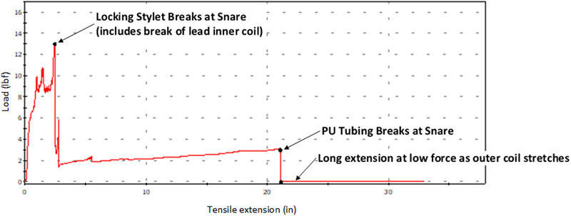
Lead extraction with the use of a fully engaged Snare. Force versus displacement curve using a fully engaged (see text) Needle Eye Snare. Traction force is borne by the locking stylet and the snare. Failure occurs at maximum force (13 lbs) when the locking stylet breaks [Color figure can be viewed at wileyonlinelibrary.com]
The location of snare attachment, and the sheath system the lead was retracted into (inner vs. outer sheath of the Needle Eye Snare) were both significant factors. To achieve maximum rail force the lead was snared over the actively locking portion of the locking stylet near the lead tip (measured ∼5 cm proximal to the lead's anode) and prolapsed into the snare inner sheath, this resulted in kinking of the locking stylet. Prolapsing a lead within the outer sheath failed to provide the critical kink necessary to stabilize the lead. With these test conditions forces of ∼13 lbf (5.90 kg) and ∼16 lbf (7.26 kg) were achieved using the Philips and Cook locking stylets, respectively, with ultimate failure occurring when the lead locking stylets broke. In test cases when the snaring occurred over the non‐active portion of the locking stylet or the lead was prolapsed into the outer catheter forces between ∼6 lb (2.72 kg) and ∼8 lb (3.63 kg) were observed, Figure 6.
FIGURE 6.

Test data using a combined inferior‐superior approach. Maximum Force data plotted for all snare test cases. Two findings are demonstrated. (1) The blue solid circles demonstrate when a Needle Eye Snare is placed distally on the lead (only 1.27 cm [0.5 inch] proximal to the anode) less force is required before lead component failure than a more proximal snare position (5.08 cm [2.0 inch]). Original testing conducted in units of inches for snare location. Traction forces of 13 lbs or greater were tolerated prior to locking stylet failure. (2) The engagement of the locking stylet within the inner sheath is critical (Blue open circle versus red diamonds). Pulling the lead/locking stylet into the inner sheath results in kinking the stylet and firmly engages the locking stylet as part of the extraction rail [Color figure can be viewed at wileyonlinelibrary.com]
5. DISCUSSION
CIED lead implantation initiates a fibrous growth process that often results in binding sites along the intravascular path and at the electrode myocardial interface. 7 , 8 Scar tissue matures over time from a soft to a more solidified and often calcified scar. 8 Significant adhesions require more forceful maneuvers with the extraction tools and as a result, increase risk for perforation of vascular and/or cardiac tissue. 9 , 10 , 11 , 12 Critical to the removal of chronically implanted CIED leads is a stable rail for the extraction tool to traverse over. That rail consists of the lead and a locking stylet deployed within.
The test method of “Tip Only Attachment” best reflects the INGEVITY lead failure mechanism. Traction forces initially load the ETFE tubing internal to the lead body until the ETFE detaches from the lead's distal coupler component and then switches to loading the single filar coil. The single filar response to load bearing initially is significant stretch and tensile loads transition to the lead's silicone flexible neck between the lead's cathode and anode electrodes and polyurethane lead body insulation. These two outer insulation components are connected in series, the silicone is the weaker material. Ultimate failure of the insulation occurs within the lead's silicone flexible neck. At this point only the single filar inner coil is attached and will continue to stretch significantly until inner coil failure and the lead is separated into two pieces.
This component failure begins at ∼2.5 lbs of traction with the greatest traction force tolerated before failure of under ∼3.5 lbs. Observational data from the Philips (Philips Healthcare, Amsterdam, Netherlands) lead extraction simulator, used in physician training, demonstrates that the average extractor measured traction “pull” force varies between ∼3 and ∼8 lbs (1.36 to 3.63 kg) (personal communication). Thus, the integrity of the INGEVITY lead experiences component failure with forces on the low end of typical range for extraction. By comparison a traditional pacemaker lead design with a multi‐filar inner coil has less capability to stretch, can bear higher loads, and will bear load more quickly when stressed as compared to a single‐filar coil of similar material and geometry. This results in less load bearing by any insulation and forces are tolerated by the stronger inner conductor coil and associated joints.
Before attempting to free the lead tip, the procedural physician may attempt retraction of a deployed pacemaker lead helix sparing lead components the traction force required to straighten an extended helix. It is difficult to retract a chronically implanted INGEVITY lead deployed helix due to inadequate torque delivery along the single filar coil. In this study we were able to retract the extended screw using a counterclockwise rotation of a deployed locking stylet in combination with the single inner coil filar. This was most successful when rotating in unison the inner coil and the locking stylet with the terminal pin intact. The Philips LLD #2 stylet was found to be superior (Figure 3) which may be due to the design difference between the Philips LLD#2 and the Cook liberator (Cook Medical, Bloomington, IN). The Philips LLD#2 locks throughout the entire lead length; whereas, the Cook Liberator locks near the distal portion. An even and effective transfer of energy down the inner coil is accomplished by counter clockwise turning in unison the connector pin and a locking stylet engaged the entire lead length. As shown in our testing this transfer of energy retracts an extended screw.
During preparation of the lead rail, traditional lead extraction techniques involve removing the terminal lead portion. This study demonstrated that retention of the INGEVITY terminal lead end resulted in an increase in lead tensile strength. Retaining the terminal end provides a backstop to coil stretch and enables engaging the lead insulation for load sharing. In clinical practice, this method will require upsizing the extraction sheath as the IS‐1 terminal pin is 9.6 Fr. This translates from a change of a 9 to 11 Fr Cook Evolution or Philips Tightrail extraction cutting sheaths and from a 12 to a 14 Fr Philips laser sheath. Additional shaving off terminal seals allows a reduction in friction between lead and extraction sheath lumen.
Of great interest is the effect of scar adherence to the forces distributed along the lead body. In this model, adherent scar participates in load bearing thus reducing the immediate loading on lead components distal to that scar, thus protecting those components. Scar and insulation bear the traction load until the lead insulation stretches or the adhesion is removed. Loading is then transferred to distal lead components. However, this study also found that a small defect in the polyurethane tubing significantly reduced the outer insulation load bearing ability leading to lead failure at that insulation damage site. Thus, a dichotomy exists where scar can add strength to the lead extraction rail but any insulation damage during an extraction removal of that scar results in loss of integrity of the extraction rail at the damaged location. These findings challenge the extractor to be aware of this finding and protect insulation during lead removal by possible changes in technique, taking care during suture sleeve removal, tool choice, tool size and lead removal sequence.
A multi‐venous approach, stabilizing a lead with the use of a femoral snare, offered the strongest rail. Snaring a locking stylet within the INGEVITY lead effectively transformed the locking stylet into the extraction rail, allowing the locking stylet to bear tensile loading. Such a rail was capable of 13‐16 lb (7.26 kg) of traction (Figure 5) before the locking stylet itself fails. Three issues are critical to effective use of a snared locking stylet as a rail. First, the snare must be deployed on the pacing lead at a location proximal to where the locking stylet has locked. Secondly, the snare must effectively engage the locking stylet. Multiple layers of insulation can prevent a firm snare and locking stylet engagement, kinking the stylet within the inner sheath is critical to success. This was accomplished by retracting the lead and locking stylet into the Cook femoral station inner sheath (Figure 7). Without firm engagement of the locking stylet, the Needle's Eye Snare is not able to fully retain the locking stylet allowing it to slide back through the lead body. Lead components then pull apart from one‐another resulting in a lower traction force achieved prior to lead failure. Thirdly, this technique requires equal traction from both the proximal and femoral approaches. Attempting to remove the lead from one direction alone will result in the same coil stretch and lead component failure described above. Thus, the approach of stabilizing the lead from both above and below would allow advancement of a extraction tool over a stable rail.
FIGURE 7.

Demonstration of the snaring technique. (A) Needle Eye Snare is used to snare the lead (A) and create a substantially harsh kink in the lead, driving the lead body to ∼180‐degree bend, and prolapse the lead fully into the inner sheath of the snare. (B) Fluoroscopic image (C) demonstrating the snare's firm grip and harsh kink anchoring the distal lead. The locking stylet provides support for an effective extraction rail [Color figure can be viewed at wileyonlinelibrary.com]
Current tools for snaring are limited by lack of adjustable curves, lack of a secondary articulation for clockwise and counter‐clockwise movement, large sizes of the snaring mechanism and requirement of pulling the snared lead/stylet into a sheath. However, this technique can be applicable in any situation where the required forces of extraction exceed the tensile strength of a lead.
6. LIMITATIONS
The model used here is an atrial lead model, not ventricular. However, we believe the concepts presented will apply to INGEVITY leads placed in the ventricle. These lead evaluations were not done in human subjects for obvious reasons and their applicability to extraction of chronically implanted leads remains to be evaluated. Only a small number of experiments were done with each configuration, however the DOE (Design Of Experiment) test approach and statistical analysis are capable of identifying statistically significant results, and we believe manufacturing consistency allows valid results with a small number of leads tested. We accept that in this model scar was a binary element which is not a true patient model where there are varying degrees of scar adherence. Lead‐lead adherence was also not discussed. Lastly this model was not designed or vetted to be an industry standard but developed as a technique to aid the understanding of best practice for extraction of INGEVITY leads.
7. CONCLUSION
Knowledge gained from the use of an in vitro model simulating atrial lead extraction forces provides insight for extraction of INGEVITY leads. Our recommendations are based on the results of this study. We found that not removing but rather preserving the lead terminal pin provides the most benefit above all other factors tested short of femoral snaring. Further, it was found easier to retract a deployed screw with a Philips locking stylet.
Scar on a lead works in conjunction with the lead body insulation. When scar firmly binds to a lead the maximum applied traction forces are considerably higher before any major break than without scar attachment. However, damage to the polyurethane body tubing dramatically reduces the traction force capable before further INGEVITY lead degradation.
Overall, in this testing, the greatest chance to maintain and preserve lead integrity was obtained by creating a firm rail between a femorally snared locking stylet within the distal end of the INGEVITY lead and the proximal end of the lead. Lead removal could then be accomplished from a superior approach.
AUTHOR CONTRIBUTIONS
Pierce J. Vatterott conceived of this study, Pierce J. Vatterott and Robert K. Lewis provided guidance based on their experience as high‐volume lead extractors. Study design, data analysis, and critical revision of the article were performed by all four authors. Drafting of the Introduction, Discussion, and Conclusions was performed by Pierce J. Vatterott; drafting of the Methods and Results was performed by Andrew De Kock and Eric F. Hammill. All four authors approve of the final manuscript. This evaluation was funded by Boston Scientific and testing was performed by Boston Scientific employees. Pierce J. Vatterott serves as a consultant to Medtronic, Boston Scientific, Philips, Cook and Inspire, and receives teaching fees from Medtronic. Robert K. Lewis serves as a consultant to Philips, Medtronic, and Boston Scientific. Andrew De Kock and Eric F. Hammill are employees of Boston Scientific.
Supporting information
Figure A1: Human Imaging converted to silicone heart model (top).
Figure A2: Critical Bends Identified in Silicone Heart Model
Figure A3: Silicone Heart Model
Figure A4: Lead Tip Clamped in Hemostats
Figure A5: Fixture setup for simulated lead tissue attachment
Figure A6: Distal tip of lead constrained by Needle Eye Snare
ACKNOWLEDGMENTS
We thank both Cook Medical (Bloomington, IN) and Philips Healthcare (Amsterdam, Netherlands) for donation of the lead extraction tools used in the testing. Boston Scientific provided INGEVITY leads and test equipment, and we thank Jeff Wodicka (Boston Scientific) for his time performing the testing.
Vatterott P, De Kock A, Hammill EF, Lewis R. Strategies to increase the INGEVITY lead strength during lead extraction procedures based on laboratory bench testing. Pacing Clin Electrophysiol. 2021;44:1320–1330. 10.1111/pace.14303
DATA AVAILABILITY STATEMENT
The data that support the findings of this study are available from the corresponding author upon reasonable request.
REFERENCES
- 1. Kusumoto FM, Schoenfeld MH, Wilkoff BL, et al. 2017 HRS expert consensus statement on cardiovascular implantable electronic device lead management and extraction. Heart Rhythm. 2017;14:e503‐e551. [DOI] [PubMed] [Google Scholar]
- 2. Le KY, Sohail MR, Friedman PA, et al. Impact of timing of device removal on mortality in patients with cardiovascular implantable electronic device infections. Heart Rhythm. 2011;8:1678‐1685. [DOI] [PubMed] [Google Scholar]
- 3. Cooke DJ, Himes A, Swerdlow CD. Improved engineering standards for transvenous cardiac leads: a progress report from the association for the advancement of medical instrumentation cardiac rhythm management device committee leads working group. Heart Rhythm. 2019;16:958‐959. [DOI] [PubMed] [Google Scholar]
- 4. Nielsen JC, Giudici M, Tolasana Viu JM, et al. Safety and effectiveness of a 6‐French MRI conditional pacemaker lead: the INGEVITYTM clinical investigation study results. Pacing Clin Electrophysiol. 2017;40:1121‐1128. [DOI] [PubMed] [Google Scholar]
- 5. Gong B, Tu Y, Zhou Y, et al, Moisture absorption characteristics of silicone rubber and its effect on dielectric properties. In: 2013 Annual Report Conference on Electrical Insulation and Dielectric Phenomena. IEEE; 2013:430‐433. [Google Scholar]
- 6. Montgomery DC. Design and Analysis of Experiments. 6th ed.. John Wiley & Sons.; 2004. [Google Scholar]
- 7. Kołodzińska A, Kutarski A, Koperski Ł, Grabowski M, Małecka B, Opolski G. Differences in encapsulating lead tissue in patients who underwent transvenous lead removal. Europace. 2012;14:994‐1001. [DOI] [PubMed] [Google Scholar]
- 8. Candinas R, Duru F, Schneider J, Lüscher TF, Stokes K. Postmortem analysis of encapsulation around long‐term ventricular endocardial pacing leads. Mayo Clin Proc. 1999;74:120‐125. [DOI] [PubMed] [Google Scholar]
- 9. Hauser RG, Katsiyiannis WT, Gornick CC, Almquist AK, Kallinen LM. Deaths and cardiovascular injuries due to device‐assisted implantable cardioverter‐defibrillator and pacemaker lead extraction. Europace. 2010;12:395‐401. [DOI] [PMC free article] [PubMed] [Google Scholar]
- 10. Segreti L, Rinaldi CA, Claridge S, et al. Procedural outcomes associated with transvenous lead extraction in patients with abandoned leads: an ESC‐EHRA ELECTRa (European Lead Extraction Controlled) registry sub‐analysis. Europace. 2019;21:645‐654. [DOI] [PubMed] [Google Scholar]
- 11. Koneru JN, Jones PW, Hammill EF, Wold N, Ellenbogen KA. Risk factors and temporal trends of complications associated with transvenous implantable cardiac defibrillator leads. J Am Heart Assoc. 2018;7:e007691. [DOI] [PMC free article] [PubMed] [Google Scholar]
- 12. Deshmukh A, Patel N, Noseworthy PA, et al. Trends in use and adverse outcomes associated with transvenous lead removal in the United States. Circulation. 2015;132:2363‐2371. [DOI] [PubMed] [Google Scholar]
Associated Data
This section collects any data citations, data availability statements, or supplementary materials included in this article.
Supplementary Materials
Figure A1: Human Imaging converted to silicone heart model (top).
Figure A2: Critical Bends Identified in Silicone Heart Model
Figure A3: Silicone Heart Model
Figure A4: Lead Tip Clamped in Hemostats
Figure A5: Fixture setup for simulated lead tissue attachment
Figure A6: Distal tip of lead constrained by Needle Eye Snare
Data Availability Statement
The data that support the findings of this study are available from the corresponding author upon reasonable request.