Abstract
Fabrication of 3D‐printed ceramic parts with high complexity and high spatial resolution often demands low wall thickness as well as high stiffness at the green state, whereas printing simpler geometries may tolerate thicker, more compliant walls with the advantage of a rapid binder‐burn‐out and sintering process. In this work, the influence of the binder system on the thermophysical properties of 3D‐printed stabilized zirconia ceramics was investigated. Samples were fabricated with the lithography‐based ceramic manufacturing (LCM) technology using two different photosensitive ceramic suspensions (LithaCon 3Y230 and LithaCon 3Y210), with the same ZrO2 powder. A significant difference in stiffness in the green state (~3 MPa vs. ~32 MPa for LithaCon 3Y230 and LithaCon 3Y210, respectively) was measured, associated with a rather loose or a linked network formed in the binder due to photopolymerization. Both materials reached high relative densities, that is, >99%, exhibiting a homogeneous fine‐grained microstructure. No significant differences on the coefficient of thermal expansion (11.18 ppm/K vs. 11.17 ppm/K) or Young's modulus (207 GPa vs. 205 GPa) were measured, thus demonstrating the potential of tailoring binder systems to achieve the required accuracy in 3D‐printed parts, without detrimental effects on material's microstructure and thermophysical properties at the sintered state.
Keywords: binders/binding, ceramic 3D‐printing, density, lithography‐based ceramic manufacturing, microstructure, polymers/polymerization, zirconia: yttria stabilized
1. INTRODUCTION
Tetragonal zirconium dioxide (ZrO2), stabilized with 3 mol% of yttrium (3Y‐TZP), bears the name of “ceramic steel”. 1 , 2 High strengths (900–1200 MPa) in combination of high fracture toughness (5–10 MPa.m1/2) have been reported, associated with the tetragonal‐monoclinic phase transformation toughening mechanism. 3 , 4 , 5 These high mechanical properties as well as high wear resistance, thermal and chemical stability, biocompatibility and low thermal conductivity as well as high ionic conductivity make ZrO2 in the tetragonal phase of high interest for various applications, such as blades, bio‐implants, especially in dentistry, electrolytes for solid oxide fuel cells or thread guides, etc.
Established ceramic processing and forming technologies such as (i) uniaxial/ isostatic pressing, (ii) slip casting, (iii) tape casting, or (iv) injection molding, have been successfully employed for the fabrication of ZrO2 parts. However, the majority of these processes are limited to the fabrication of parts of rather simple geometry. Processes such as injection molding, where parts of high complexity can be made, are of high costs and require laborious manufacturing of complex molds. Other aspiring technologies such as 3D printing have established new paths for a rather low cost and customized, without post‐machining, fabrication of complex ceramic parts. In this regard, various 3D printing processes have been utilized to fabricate zirconia ceramics. 6 , 7 , 8 Among those selective laser sintering (SLS®), binder jetting, Fused deposition modeling (FDM®), or Stereolithography (SL) / Digital Light Processing (DLP) may be highlighted. 9
One of the key aspects of using 3D printing is to achieve high geometric accuracy and high resolution of the “green bodies,” with the corresponding effect on physical and structural properties of the sintered parts. Among the above‐mentioned techniques, and thanks to the selection of appropriate binder systems and firing processes, SLA and DLP, in general, Vat photopolymerization, show promising achievements in high resolution of the green printed parts, as well as microstructure and properties after sintering, comparable to ZrO2 ceramics fabricated through conventional forming processes. 6 , 10 , 11 , 12 , 13
A key feature of vat photopolymerization is the use of light‐sensitive polymer systems, filled with ceramic powders, for layer‐by‐layer solidification. The selection of the monomer system in the suspension is crucial to provide stiffness to the green part. The question raises whether the different “green” properties may have a significant influence on the final ceramic parts.
In this work, the effect of the binder system on the “green” stiffness, maximum wall thickness, density, microstructure, and thermophysical properties of sintered zirconia ceramics is investigated. Monomers of different functionality are selected for the binder employed in the suspensions: (A) mono and difunctional monomers, (B) multifunctional monomers. System A is prone to develop a rather loose polymer network during printing, which may result in lower green stiffness, thus limiting the feasibility of fabricating parts of fine structures. System B exhibits a strong polymeric network during photopolymerization in the printing process, which results in a rather high green stiffness for the easier printing of very fine structures of high resolution. However, binder‐burn‐out in the latter turns out to be more complex, which may result in a lower maximum attainable wall thickness.
In this investigation, ZrO2 parts are fabricated using the lithography‐based ceramic manufacturing (LCM) technology based on DLP, as developed by Lithoz GmbH. 14 , 15 In the LCM technology, parts are printed layer‐by‐layer in a bottom‐up setup, out of a filled photosensitive suspension due to photopolymerization. The two different photosensitive ceramic suspensions (LithaCon 3Y230 and LithaCon 3Y210), corresponding to binder system A and B, respectively, contain the same ZrO2 powder with slightly different solid loading content. Green stiffness, maximum wall thickness, density, Young's modulus, and coefficient of thermal expansion are determined and compared. Vickers hardness is also compared to provide preliminary results on the structural properties of both systems. The feasibility of printing ZrO2 parts of high complexity, with high resolution as well as thermophysical properties comparable to commercially fabricated samples, is discussed.
2. EXPERIMENTAL PROCEDURE
2.1. Materials of study and samples
Two different photosensitive ceramic suspensions were developed, containing the same submicron granular ZrO2 powder (D50 ~ 0.4 µm) but different binder systems and ceramic solid loading. System “A”, referred to as LithaCon3Y230 (Lithoz GmbH, Vienna, Austria), contains mono/di‐functional (meth‐) acrylate used for photopolymerization and a solid loading of ~44 vol%. System “B”, named as LithaCon3Y210 (Lithoz GmbH, Vienna, Austria) employs mainly (meth‐)acrylates with multifunctionality and has a solid loading of ~48 vol%. All samples were printed with a CeraFab 7500 3D printer (Lithoz GmbH, Vienna, Austria), using the LCM technology. Two different states may be distinguished in this investigation: (a) green state, and (b) sintered state. The green state is defined as the state after printing, where the ceramic powder has been shaped, but is still surrounded by the photocured polymeric matrix. The thermal post‐processing of the samples in the green state can be divided into two steps: (i) the debinding step, where the green part is thermally treated until 600℃ to remove the polymeric binder; and (ii) the firing step, where the open porous structure after debinding is heated to 1450℃ to reach a fully dense body. The terminology for system A and B is adapted according to the state of processing: (i) “suspension” for the viscous state, (ii) “green‐body” for the state after printing, and (iii) “ceramic” for the sintered state.
Sample geometries for the determination of the various material properties in the green as well as in the sintered state are listed in Table 1. Since the LCM technology manufactures the samples using a layer‐by‐layer approach, 16 the direction of the layers with respect to the testing direction, for green stiffness evaluation, was taken into account.
TABLE 1.
Material properties and corresponding testing geometries for the samples either in “green” or sintered state
| Measured property | Geometry and measuring standards | State |
|---|---|---|
| Green Stiffness | Tensile test rod (l3 = 35 mm, b1 = 2 mm), ISO 527‐1BB 17 , 18 | green |
| Wall Thickness | Cylinders (diameter: 3‐8 mm; height: 10 mm) | sintered |
| Density | Cylinders (diameter: 6 mm; height: 10 mm) | sintered |
| Young's Modulus | Prismatic bar (4 × 3 × 45 mm), ISO 843‐2 19 | sintered |
| Coefficient of Thermal Expansion | Prismatic bar (4 x 3 x 25 mm) EN 821‐1 20 | sintered |
2.2. Printing process
The different formulation of the binder systems and the varying solids loadings of suspension A and B result in different viscosity and printing properties. The printing processes for both suspensions (A and B) were performed at a constant temperature of 30℃, and the relative humidity was below 40%. The dynamic viscosity (ƞ) of suspension A was ~10.2 Pa⋅s at a shear rate of 20 s−1 at a temperature of 30℃, in comparison for suspension B ƞ(30℃) ~10.9 Pa⋅s at 20 s−1. Both suspensions were printed applying a layer thickness of 25 µm. However, the applied exposure energy (Eexp ) for suspension A is in general set to Eexp ~175 mJ/cm2, whereas for suspension B it is Eexp ~100 mJ/cm2. Due to the different solids loadings of suspension A and B the shrinkage of 3D‐printed occurs in an anisotropic fashion, resulting in different shrinking compensations in xy‐ and z‐direction. For suspension A and B shrinking compensation factors of 1.283 and 1.270 were applied in xy‐direction, and 1.323 and 1.300 in z‐direction, respectively.
2.3. Thermal post processing
After printing, the samples were stored in a drying chamber at a temperature of 120℃. The further thermal post processing, debinding (<600℃) and sintering (1450℃), was performed in one thermal treatment cycle for the applied green‐bodies A and B. For a better visualization, the debinding and firing step are shown separately in Figure 1. According to the debinding steps for green‐body A and B, the treatments are different due to the different complexities of the developed polymeric networks (Figure 1A). Considering green‐body A with a rather loose network, a debinding cycle with fewer temperature plateaus and “short” total duration (~52 h) was applied. In comparison, for green‐body B, with a complex polymerized network, the debinding step shows longer dwelling times at numerous temperature plateaus and low heating rates, resulting in a total duration of ~76 h. Whereas the heating rates and dwelling times are equal for both systems (A and B) in the sintering step, the cooling rates are different (Figure 1B). The lower cooling rate for body A is selected to guarantee a homogeneous cooling in samples of larger wall thicknesses.
FIGURE 1.
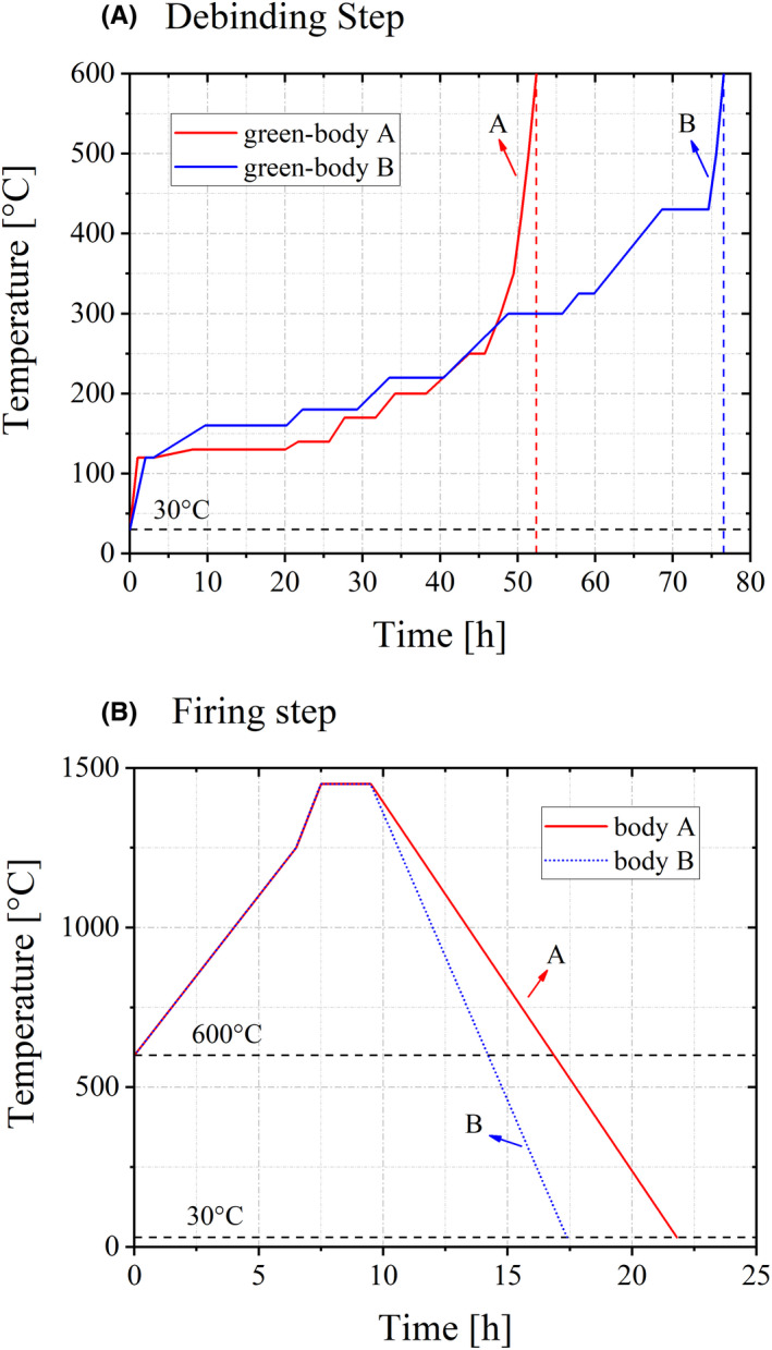
Thermal post‐processing of green‐body A and B divided in the (A) debinding step and (B) firing step
2.4. Microstructural analysis
Selected samples of sintered material corresponding to ceramic A and B were polished to 1 µm mirror finish with a Struers RotoForce4 equipment. The polished samples were further thermally etched at 1450℃ for 40min to reveal microstructural features. The finished surface was coated using an Agrar Sputter Coater and observed using a scanning electron microscope, SEM (JEOL JCM‐6000Plus, NeoscopeTM, JEOL Ltd.). The average grain size and the distribution were evaluated applying the point‐counting method on ~1000 grains in random directions. 21
2.5. Evaluation of materials properties
2.5.1. Green stiffness
In the LCM technology the stiffness of a printed sample in the green state is crucial for the manufacturing of highly complex and fine geometries. Green stiffness was measured of both green‐bodies, A and B, by means of tensile tests according to DIN EN ISO 3167, 18 employing tensile rod ISO‐527 1BB geometry. 17 The rods were tested, using a universal testing machine (MTS Synergie 200). First, a preload of 0.2 N was applied with a speed of 1.0 mm/min to the clamped green rods and dwelled for 5 s for relaxation. In the next step, the load was increased with a speed of 5.0 mm/min until failure. The green stiffness was evaluated by determining the slope of the stress‐strain curve, in the strain range of 0.005–0.500%, representing the elastic behavior of the green bodies.
2.5.2. Maximum wall thickness
Besides the green stiffness, the complexity and strength of the polymer network formed during light exposure also controls the maximum wall thickness after sintering of stereolithographically printed ceramic parts. During the debinding step, the polymers degrade and dissolve, causing stresses inside the polymer‐ceramic‐composite. It is crucial to distinguish, whether the polymer used for photopolymerization in the suspensions is (i) mono‐functional or (ii) multi‐functional. The maximum wall thickness (MWT) is the maximum diameter of a cylinder that can be manufactured with no cracks in the sintered body. To determine the MWT, cylinders of different diameters, from 3 to 8 mm, and a height of 10 mm were printed, debinded, and sintered. After every processing step, the cylinders were optically analyzed using a light microscope. The sintered parts were further inspected using a dye penetrant to reveal the presence of possible cracks.
2.5.3. Density
The bulk mass density (ρ b) of three sintered zirconia samples was measured after the Archimedes principle according to EN‐623‐2. 22 The theoretical density of zirconia (ρ th = 6.088 g/cm3), used for density calculations was provided by the ceramic powder supplier. The relative densities (ρ rel) were calculated as ρ rel = ρ b / ρ th.
2.5.4. Young's modulus
The elastic modulus of the zirconia sintered samples from ceramics A and B was evaluated under three‐point bending following the EN 843‐2 standards. 19 A universal testing machine with a 100 N load cell was used (Messphysik, Microstrain, Fürstenfeld, Austria). The average Young's modulus was determined from three bending bars (4 × 3 × 45 mm) of each material using a three‐point bend set‐up with a 40 mm outer span. Load‐displacement curves were measured during alternating loading/unloading cycles. The cycles were controlled by displacement with a crosshead speed of 0.5 mm/min. The selected preload was 2 N and the maximum load 50 N, respectively, for both ceramics. Tests were performed in ambient conditions (23℃ and ~24% relative humidity).
2.5.5. Coefficient of thermal expansion
A dilatometer (Netzsch – Thermal Analysis, 95100 Selb, Germany) was employed to determine the coefficient of thermal expansion (CTE), for both ceramics, A and B. The change in length with temperature was measured in bend bars with a cross section of 4x3 mm and a length of 25 mm, for a temperature range from 30℃ to 900℃. The heating as well as the cooling rate were 5℃/min, respectively, and at each 100℃ segment a dwelling time of 1 h was held. The measured data were further used for the calculation of the CTE, using 25℃ as reference temperature. 20
2.5.6. Vickers hardness
For the evaluation of the Vickers Hardness (HV) a side surface of a testing bar of each ceramic, A and B, was polished to a 1 µm mirror finish for a better imprint identification of the indent. A load of 5 kg was applied using a pyramid‐shaped diamond indenter on a Zwick Indenter machine (ZwickRoell GmbH & Co). For statistical significance, 20 indents were performed at two polished surfaces of each material. The corresponding Vickers Hardness (HV5) was evaluated according to the EN 843‐4 standards. 23 Crack lengths were measured to qualitatively compare the resistance of both A and B ceramics to the propagation of surface cracks.
3. RESULTS AND DISCUSSION
3.1. Materials properties of green bodies
The main difference between systems A and B is at the green state of the printed parts. Figure 2 shows two representative stress–strain curves of a certain strain range for the determination of the green stiffness for green‐body A and B.
FIGURE 2.
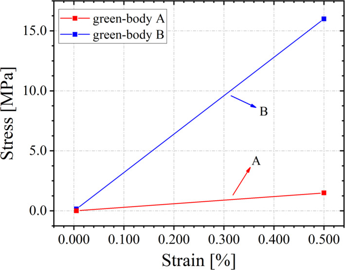
Stress–strain curves of green‐body A and B for determination of the green stiffness
Whereas green‐body A exhibits a rather low green stiffness of ~3 MPa, the green stiffness of green‐body B was ~32 MPa. This difference can be explained by the distinct polymer network developed during the printing process, that is, in green‐body A a rather loose network, and in green‐body B a rather strong network.
3.2. Materials properties of sintered bodies
3.2.1. Microstructure and density
Figure 3 displays polished surfaces to illustrate the microstructure for (A) ceramic A and (B) ceramic B. Both ceramics exhibited a fine grained, homogenous, and dense microstructure after sintering. In Figure 4, the evaluated grain size distributions for both ceramics (A and B) are compared.
FIGURE 3.
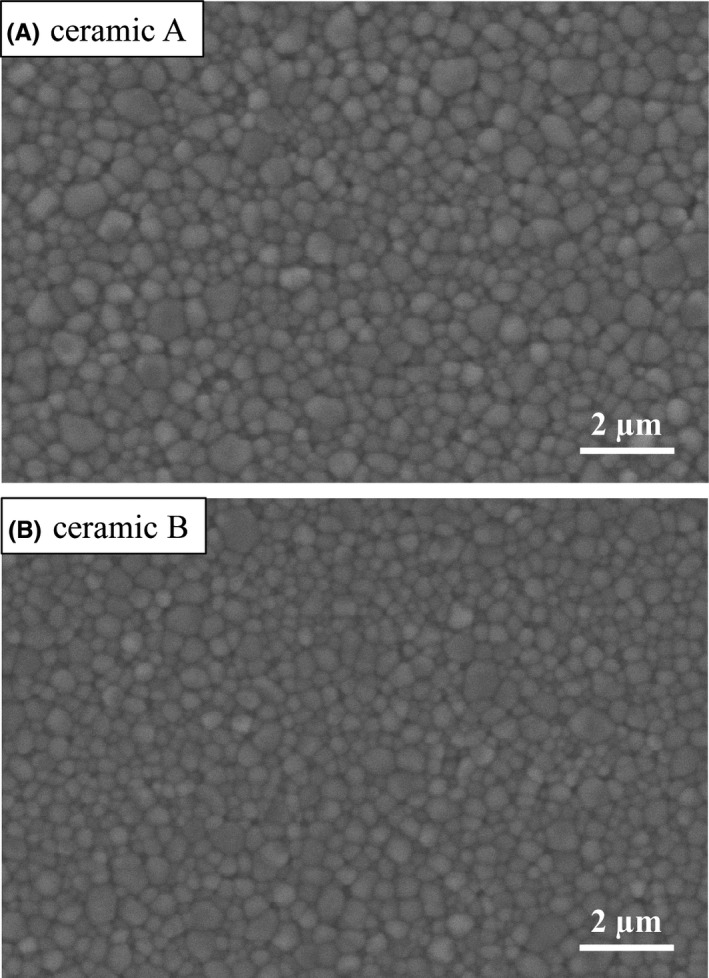
SEM images of the microstructure of (A) ceramic A and (B) ceramic B
FIGURE 4.
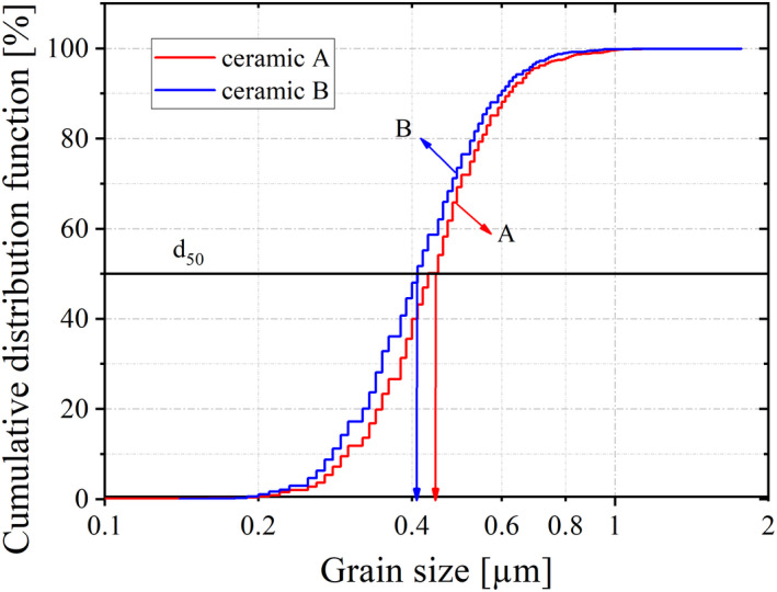
Grain size distribution of systems A and B
According to the measured grain size distribution, ceramic A has a slightly larger average grain size of ~0.45 ± 0.01 µm in comparison to ceramic B, i.e., ~0.43 ± 0.02 µm. This slight difference in grain size of the two ceramics displays a tendency and may be associated with the distinct solids loading of ceramic powder in the viscous suspensions (i.e., ~44 vol% for suspension A vs. ~48 vol% for suspension B). No porosity could be observed in the micrographs analyzed. For both materials, a relative density >99% was measured (see Table 2). To our knowledge, this density value has never been reported for zirconia fabricated with additive manufacturing employing stereolithography. 6 , 11 , 24 , 25
TABLE 2.
Thermophysical properties of material A and B
| Material property |
ρrel [%] |
E‐Modulus [GPa] |
CTE (25‐900℃) [ppm/°C] |
HV [GPa] |
|---|---|---|---|---|
| Material A | 99.37 ± 0.12 | 207 ± 1 | 11.18 ± 0.05 | 13.5 ± 0.1 |
| Material B | 99.35 ± 0.14 | 205 ± 1 | 11.17 ± 0.06 | 13.6 ± 0.2 |
3.2.2. Structural and thermophysical properties
For ceramic A, the maximum wall thickness in the sintered state, reached ~6.2 mm, whereas for sintered ceramic B, the measured maximum wall thickness was ~4.7 mm. The difference in MWT of the investigated ceramics can be correlated to the difference in complexity of the developed network during photopolymerization in the green‐bodies A and B, affecting the degradation behavior during binder‐burn‐out.
Representative curves of the E‐Modulus measurements in Figure 5 show the identical elastic behavior of the two ceramics A and B. The values for αtech (technical CTE) for the temperature range of 25–900℃ are almost identical (i.e., ~11.2 ppm/K) for both ceramics A and B (Table 2).
FIGURE 5.
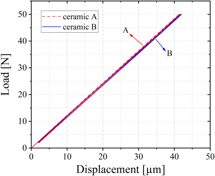
Load–displacement curve for system A and B
Figure 6 shows representative Vickers indentations at a load of 5 kg for (A) ceramic A and (B) ceramic B. The total crack length (2a), from crack tip‐to‐tip in the vertical and horizontal direction, was measured on ten indents of each ceramic. The average crack length for ceramic A was 172 ± 3 µm and 175 ± 2 µm for ceramic B, respectively. These measured values do not statistically differ, indicating that mechanical properties (such as strength and fracture toughness) of both ceramics are expected to show strong similarities.
FIGURE 6.
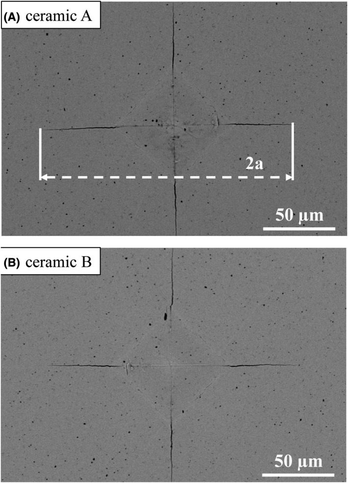
Vickers indentations (5 kg) for (A) ceramic A and (B) ceramic B
In Table 2, the relative density (ρ rel), the Young's modulus (E), the Vickers Hardness (HV) as well as the coefficient of thermal expansion in a temperature range of 25‐900℃ (CTE) are summarized for ceramics A and B.
The properties measured for ceramics A and B are almost identical. In addition, the Young's moduli of ∼205 GPa, the CTE of ∼11 ppm/°C as well as the Vickers Hardness ∼13.5 GPa are comparable to the properties achieved with conventional fabrication methods for the same zirconia material. 2 , 5 These results indicate the potential of tailoring binder systems to achieve the required accuracy in 3D‐printed parts, without affecting the material's microstructure and thermophysical properties of the sintered parts.
4. CONCLUSION
The effect of photosensitive binder systems investigated on two commercially available suspensions (LithaCon 3Y230 and LithaCon 3Y210) with the same ZrO2 powder revealed a strong difference in material stiffness at the green state (i.e. ~3 MPa vs. ~32 MPa). Relative densities higher than 99% were measured in both ceramics after sintering, showing no apparent porosity and an homogenous fine‐grained microstructure. Thermophysical properties of the sintered ceramic parts for both systems, manufactured using the LCM process, did not reveal significant differences. This indicates the feasibility of printing simple or bulky geometries with large wall thickness (3–7 mm), such as valves, bearings, or cutting tools with the system LithaCon 3Y230. In comparison, for rather complex and fine geometries with smaller wall thicknesses (<3 mm), as in the medical industry for mandible or dental implants, or as filters and nozzles in the field of technical applications, the system LithaCon 3Y210 fulfills the conditions of high resolutions and high green stiffness.
ACKNOWLEDGMENT
The funding for this research was provided by the European Research Council (ERC) excellent science grant “CERATEXT” through the Horizon 2020 program under contract 817615.
Hofer A‐K, Rabitsch J, Jutrzenka‐Trzebiatowska D, Hofstetter C, Gavalda‐Velasco I, Schlacher J, et al. Effect of binder system on the thermophysical properties of 3D‐printed zirconia ceramics. Int J Appl Ceram Technol. 2022;19:174–180. 10.1111/ijac.13806
REFERENCES
- 1. Garvie RC, Hannink RH, Pascoe RT. Ceramic steel? Nature. 1975. 258(5537):703–4. [Google Scholar]
- 2. Chevalier J, Liens A, Reveron H, Zhang F, Reynaud P, Douillard T, et al. Forty years after the promise of «ceramic steel?»: Zirconia‐based composites with a metal‐like mechanical behavior. J Am Ceram Soc. 2020;103(3):1482–513. [Google Scholar]
- 3. Piconi C, Maccauro G. Zirconia as a ceramic biomaterial. Biomaterials. 1999;20(1):1–25. [DOI] [PubMed] [Google Scholar]
- 4. Chen Y‐W, Moussi J, Drury JL, Wataha JC. Zirconia in biomedical applications. Expert Rev Med Devices. 2016;13(10):945–63. [DOI] [PubMed] [Google Scholar]
- 5. Salmang H, Scholze H, editors. Keramik, 7th edn. Berlin: Springer; 2007. [Google Scholar]
- 6. Zhang X, Wu X, Shi J. Additive manufacturing of zirconia ceramics: a state‐of‐the‐art review. Journal of Materials Research and Technology. 2020;9(4):9029–48. [Google Scholar]
- 7. Wang J‐C, Dommati H, Hsieh S‐J. Review of additive manufacturing methods for high‐performance ceramic materials. Int J Adv Manuf Technol. 2019;103(5–8):2627–47. [Google Scholar]
- 8. Chen Z, Li Z, Li J, Liu C, Lao C, Fu Y, et al. 3D printing of ceramics: a review. J Eur Ceram Soc. 2019;39(4):661–87. [Google Scholar]
- 9. F42 Committee . Terminology for Additive Manufacturing Technologies. West Conshohocken, PA: ASTM International. [Google Scholar]
- 10. Mitteramskogler G, Gmeiner R, Felzmann R, Gruber S, Hofstetter C, Stampfl J, et al. Light curing strategies for lithography‐based additive manufacturing of customized ceramics. Additive Manufacturing. 2014;1–4:110–8. [Google Scholar]
- 11. Zhang K, He R, Ding G, Feng C, Song W, Fang D. Digital light processing of 3Y‐TZP strengthened ZrO2 ceramics. Mater Sci Eng, A. 2020;774:138768. [Google Scholar]
- 12. Conti L, Bienenstein D, Borlaf M, Graule T. Effects of the layer height and exposure energy on the lateral resolution of zirconia parts printed by lithography‐based additive manufacturing. Materials (Basel). 2020;13(6):1317. [DOI] [PMC free article] [PubMed] [Google Scholar]
- 13. Li X, Zhong H, Zhang J, Duan Y, Li J, Jiang D. Fabrication of zirconia all‐ceramic crown via DLP‐based stereolithography. Int J Appl Ceram Technol. 2020;17(3):844–53. [Google Scholar]
- 14. Schwentenwein M, Homa J. Additive manufacturing of dense alumina ceramics. Int J Appl Ceram Technol. 2015;12(1):1–7. [Google Scholar]
- 15. Lantada AD, de Blas Romero A, Schwentenwein M, Jellinek C, Homa J. Lithography‐based ceramic manufacture (LCM) of auxetic structures: present capabilities and challenges. Smart Mater Struct. 2016;25(5):54015. [Google Scholar]
- 16. Schlacher J, Lube T, Harrer W, Mitteramskogler G, Schwentenwein M, Danzer R, et al. Strength of additive manufactured alumina. J Eur Ceram Soc. 2020;40(14):4737–45. [Google Scholar]
- 17. DIN EN ISO 527‐2 (2012‐06) . Kunststoffe – Bestimmung der Zugeigenschaften – Teil 2: Prüfbedingungen für Form‐ und Extrusionsmassen.
- 18. DIN EN ISO 3167 (2014‐11) . Kunststoffe – Vielzweckprüfkörper.
- 19. DIN EN 843‐2 . Hochleistungskeramik ‐ Monolithische Keramik ‐ Mechanische Eigenschaft bei Raumtemperatur ‐ Teil 2: Bestimmung des E‐Moduls; 1995.
- 20. OENORM EN 821‐1 . Advanced technical ceramics ‐ Monolithic ceramics ‐ Termo‐physical properties ‐ Part 1: Determination of thermal expansion.
- 21. OENORM EN 623‐3 . Advanced technical ceramics – Monolithic ceramics – General and textural properties – Part 3: Determination of grain size and size distribution (characterized by the Linear Intercept Method); 2003.
- 22. EN‐623‐2 . Hochleistungskeramik ‐ Monolithische Keramik ‐ Allgemeine und strukturelle Eigenschaften ‐ Teil 2: Bestimmung von Dichte und Porosität; 1994.
- 23. OENORM ENV‐843‐4 . Advanced technical ceramics ‐ Monolithic ceramics ‐ Mechanical properties at room temperature ‐ Part 4: Vickers, Knoop and Rockwell superficial hardness.
- 24. He R, Liu W, Wu Z, An DI, Huang M, Wu H, et al. Fabrication of complex‐shaped zirconia ceramic parts via a DLP‐ stereolithography‐based 3D printing method. Ceram Int. 2018;44(3):3412–6. [Google Scholar]
- 25. Li H, Song L, Sun J, Ma J, Shen Z. Stereolithography‐fabricated zirconia dental prostheses: concerns based on clinical requirements. Adv Appl Ceram. 2020;119(5–6):236–43. [Google Scholar]


