

Abstract
The search for new rapid diagnostic tests for malaria is a priority for developing an efficient strategy to fight this endemic disease, which affects more than 3 billion people worldwide. In this study, we characterize systematically an easy‐to‐operate lab‐on‐chip, designed for the magnetophoretic capture of malaria‐infected red blood cells (RBCs). The method relies on the positive magnetic susceptibility of infected RBCs with respect to blood plasma. A matrix of nickel posts fabricated in a silicon chip placed face down is aimed at attracting infected cells, while healthy cells sediment on a glass slide under the action of gravity. Using a model of infected RBCs, that is, erythrocytes with methemoglobin, we obtained a capture efficiency of about 70% after 10 min in static conditions. By proper agitation, the capture efficiency reached 85% after just 5 min. Sample preparation requires only a 1:10 volume dilution of whole blood, previously treated with heparin, in a phosphate‐buffered solution. Nonspecific attraction of untreated RBCs was not observed in the same time interval.
Keywords: lab‐on‐a‐chip, malaria, magnetorphoretic separation
An easy‐to‐operate, flow‐less lab‐on‐chip for the magnetophoretic capture of malaria‐infected red blood cells was devised. A matrix of nickel posts fabricated in a silicon chip placed face down attracts infected cells, while healthy cells sediment on a glass slide under the action of gravity. The authors systematically characterized the chip using a model of infected red blood cells.

1. INTRODUCTION
Despite references to malaria are present throughout recorded history, since the very beginning of human civilization, 3.2 billion people are still at risk for malaria according to the World Health Organization (WHO). 228 million new cases and 405,000 deaths in 2018 were estimated (WHO, 2018).
The increased mobility, globalization, and immigration phenomena have caused some resurgence of malaria also in Western countries, where it was eradicated in the last century. In parallel, we are constantly witnessing cases of large local resurgence, with hot spots, such as the Greater Mekong region. As in a race against time, the disease should be promptly stopped there, to avoid the multiplication and spreading of worse, drug‐resistant parasites (Nature, 2018).
In the absence of an adequate vaccine, the crucial factor is avoiding delays in basic malaria control measures (Cohen et al., 2012), by ensuring early‐stage diagnosis and prompt treatment with artemisinin‐based combination therapies. Conventional diagnostic tests, via optical microscopy examination of red blood cells (RBCs) in thick and thin blood smears, are unsuitable for an effective early screening of the population, mainly because of the time required for each test (30 min to 1 h), combined with the need for a good optical microscope and an expert microscopist. More recently, rapid diagnostic tests (RDTs) based on the detection of antigens have been introduced. While RDTs feature a shorter execution time, on the order of 20 min, their limit of detection (LoD) is quite high (200 parasites/µl of blood) and they are affected by a sizeable number of false positive and false negative results, due to the difficulty to detect non‐falciparum species, pfHRP2/3 gene deletions and delayed clearance dynamics for Plasmodium falciparum (Gupta et al., 2017; Yerlikaya et al., 2018). Molecular tests based on polymerase chain reaction, and suitable for on‐field application, are highly sensitive but still quite expensive and not rapid (Lucchi et al., 2016).
For these reasons, WHO strongly recommends the development of novel RDTs with the same LoD of the time‐honored gold standard (i.e., optical microscopy examination) but a lower percentage of false positive/negative results with respect to antigen‐based RDTs (Grimberg & Grimberg, 2016; Roberts, 2016; WHO, 2017).
It is well known that infected RBCs (i‐RBCs) display a paramagnetic behavior with respect to blood plasma. Hence, a high magnetic field gradient can be used to separate i‐RBCs from healthy RBCs (h‐RBCs; Bertacco et al., 2017, 2019; Blue Martin et al., 2017; Han & Frazier, 2006; Ribaut et al., 2008). The origin of i‐RBC paramagnetism is related to the degradation of hemoglobin into free heme during the intraerythrocytic development of the plasmodium parasite. This molecule, which is highly toxic to the parasite, is converted into an insoluble form, known as hemozoin or malaria pigment, which crystallizes into paramagnetic nanocrystals (Han & Bruno Frazier, 2004), found both within the i‐RBCs and free in plasma, after RBCs lysis (Giacometti et al., 2018; Kim et al., 2012).
Many different solutions were proposed to exploit this difference in magnetic susceptibility. The most widespread one (magnetic‐activated cell sorting, or MACS) exploits a metallic ferromagnetic wool, which is inserted in blood filtration columns. In a strong external magnetic field, the ferromagnetic wool wires act as sources of a strong local magnetic field gradient, which provides a magnetic force on paramagnetic i‐RBCs. Such magnetic force counteracts gravity and drag forces, so that i‐RBCs are attracted and retained (Hänscheid et al., 2007; Noland et al., 2003). The microfluidic version of MACS uses an individual ferromagnetic wire acting as a field concentrator and providing a strong field gradient in a microfluidic channel placed nearby. Flowing i‐RBCs are thus deviated with respect to the natural trajectory followed by uninfected cells, facilitating separation of the two RBC populations (Blue Martin et al., 2017; Ribaut et al., 2008).
In view of the development of a simple test suitable for on‐field application, not requiring an extensive use of microfluidics, we have recently proposed and successfully tested a capture method in which the selective separation of i‐RBCs from h‐RBCs occurs applying magnetophoresis to a static sample of gravity‐sedimenting RBCs (Giacometti et al., 2021; Milesi et al., 2020). The possibility to successfully exploit the competition between magnetic and gravity forces under flow was demonstrated in earlier works (Karl et al., 2008; Kasetsirikul et al., 2016; Mata‐Cantero et al., 2014; Sumari et al., 2016; Zimmerman et al., 2006). The concept of our flow‐less method is shown in Figure 1. A blood smear, treated with anticoagulant and diluted with PBS, is placed on a glass slide, and covered with a silicon chip facing downwards. The slide‐to‐chip distance is set by a surrounding gasket, which defines the boundaries of a static blood cell where the analysis takes place. Due to their positive magnetic susceptibility with respect to plasma, under the action of a static external magnetic field, i‐RBCs are attracted toward a matrix of nickel posts fabricated in the silicon chip, while h‐RBCs sediment under the action of gravity. Upon calibration of the capture efficiency, the counting of the RBCs captured on the Ni posts can be used for a quantitative estimate of parasitemia, that is, the percentage of i‐RBCs with respect to the total number of RBCs.
Figure 1.

Concept of the method for the magnetophoretic separation of malaria‐infected red blood cells. Under the action of the magnetic field gradient produced by Ni microposts on a microchip in the external field H e, infected RBC are captured by the Ni posts, while healthy RBCs sediment on a glass slide
In this study, we report on the optimization of the chip and test conditions to ensure large capture efficiency in a short time. As a model system for i‐RBCs we used RBCs treated with NaNO2 (t‐RBCs) to convert hemoglobin into paramagnetic methemoglobin (Keszler et al., 2008; Rodkey, 1976). Most experiments were performed with bovine blood samples, after validation of this model against blood samples from human healthy donors. RBC capture was quantified via real‐time fluorescence optical microscopy and cell counting. A detailed optimization in static conditions was carried out with respect to the geometry of the Ni post matrix, cell height, and blood hematocrit. For this study, we used mixtures of t‐RBCs and untreated RBCs (u‐RBCs), suspended in a solution (1:10) of plasma and PBS after removal of the buffy coat.
2. MATERIALS AND METHODS
2.1. Chip layout and fabrication
Matrices of Ni posts arranged in a hexagonal close‐packed (hcp) lattice, according to the geometry shown in Figure 2b, were fabricated on a heavily p‐doped Si wafer (P+/Boron, 0.005–0.025 Ω cm) via a multistep process illustrated in Figure 2a.
Figure 2.

(a) Process flow for the fabrication of the microchip. (b) Chip layout (top view); D is post diameter, S is post spacing in the hcp lattice; scale bar is 20 µm. (c) Magnetization loops from arrays of Ni posts for applied field in the plane of the chip (IP) or perpendicular to it (OOP)
The hcp lattice is first defined by opening circular holes in a 40‐µm positive resist by optical lithography. Then, reactive ion etching is used to obtain cylindrical holes in the silicon wafer, employing a Bosch‐like process. Hole depth was limited to 20 μm, due to some limitations of the reactive ion etching machine available, and the intrinsic difficulty in filling by electroplating holes with high aspect ratio.
A uniform seed layer of Ni (20 nm thick) is then uniformly deposited by electron beam evaporation. Upon lift‐off, the seed layer is left only at the bottom of the holes, to facilitate the uniform filling of holes by electroplating. This is achieved by using a periodic reverse electroplating procedure. During 80% of the period (15 ms), a positive current is applied, causing Ni deposition, while a negative current, with lower intensity (25%) is applied for the remaining 20% of the period.
To ensure a complete filling of all holes over large areas of the chip, we overfill them by prolonging the electroplating, so to obtain characteristic “Ni‐mushrooms” with chapels protruding from the Si wafer.
After subsequent planarization via mechanical polishing, a 3‐µm SiO2 layer is deposited all over the chip by plasma‐enhanced chemical vapor deposition to create a uniform coating that prevents nonspecific sticking.
In this study, different chips with 20‐µm‐tall Ni posts were produced, by varying the post diameter (d) and spacing (s) in the hcp lattice. Throughout the paper, the sample geometry will be identified with a string d−s, where both d and s are expressed in µm.
The magnetic properties of chips with microfabricated Ni posts were investigated using a vibrating sample magnetometer (Microsense). A characteristic curve of magnetization (M) versus the applied magnetic field (H) is reported in Figure 2c, for H applied perpendicular (parallel) to the chip surface, that is, parallel (perpendicular) to the axis of cylinders. The diameter here was 40 µm.
As expected because of the low magnetocrystalline anisotropy of Ni, in both cases there is no hysteresis, and the curve is linear up to a saturation field of about 175 (250) kA·m− 1. In both cases, the saturation field is lower than the typical fields produced by the assembly of two NdFeB permanent magnets used in this study, on the order of 600 kA·m− 1.
The larger saturation field for out‐of‐plane measurements is due to shape anisotropy favoring an in‐plane magnetization, as the height of the posts is half their diameter.
2.2. Setup for magnetophoretic capture experiments
A cross section of the setup used for the experiments of magnetophoretic capture is shown in Figure 3a.
Figure 3.

(a) Cross section of the setup for the experiments of magnetophoretic capture. (b) Simulated spatial distribution of the gradient of the H 2 field produced by the assembly of the external magnets. Arrows indicate the direction of ∇H 2, that is, of the magnetophoretic force, while its intensity is given by the color plot
The sample drop is collected on the surface of a glass slide with a well of height δ, defined by opening a square hole in a polymeric coating. The sample volumes are 2, 4, or 6 µl for δ = 20, 40, or 60 µm, respectively. The microchip, with its Ni posts facing downwards, is then placed to cap the sample well, so as to expose RBCs to the maximum field gradient produced by Ni posts in their close proximity.
Above the slide‐and‐chip arrangement, an assembly of permanent magnets produces a field high enough to saturate the Ni pillars and with an intrinsic gradient high enough to balance the sedimentation force for i‐RBCs or t‐RBCs.
RBCs treated with NaNO2 display a positive magnetic susceptibility (∆χ) with respect to plasma, on the order of 3.9 × 10− 6, slightly larger than that of RBCs infected by malaria, 1.8 × 10− 6 (Blue Martin et al., 2017; Ribaut et al., 2008).
By assuming an average RBC volume V RBC = 9.1 × 10− 11 cm3, an RBC density ρ RBC = 1.15 g cm−3 and a plasma density ρ p = 1.025 g cm−3 (Blue Martin et al., 2017; Ribaut et al., 2008) the sedimentation force, calculated as the sum of gravity and buoyancy force on a treated RBC, F gb = (ρ RBC − ρ p ) × V RBC × g (see Figure 1), turns out to be 1.1 × 10− 13 N.
According to the expression for the magnetic force on a paramagnetic particle, F M = ½ µ 0 V RBC ∆χ ∇H 2, the value for the gradient of H 2 needed to balance F gb is on the order of 5 × 10¹⁴ A2 m− 3.
To produce that high gradient we use two NdFeB magnets in shape of parallelepipeds with square base, having remanent magnetization perpendicular to their base. The two magnets are placed with the magnetization pointing toward a µ‐metal sheet, 0.2 mm thick, interposed between their bases.
Due to the strong magnetic repulsions between magnetic charges of the same sign, the magnets are mechanically clamped to be kept in contact to the µ‐metal sheet.
This peculiar arrangement produces a very intense magnetic field emanating from the µ‐metal sheet, mainly along the out‐of‐plane direction of the chip (z‐direction in Figure 3), with mirror symmetry with respect to the xz plane, almost independent of the x coordinate in the central zone of the magnet.
In this study, we have used two kind of magnets: (M1) N42 grade from Supermagnete (https://www.supermagnete.it/), in shape of parallelepipeds with 20 × 20 × 5 mm3 size and (M2) N52 grade from K&J Magnetics, in shape of parallelepipeds with 25.4 × 25.4 × 6 mm3 size.
2.3. Multiphysics simulations of magnetophoretic separation
To optimize the pillar geometry and verify the capture capability of the system, numerical simulations using Comsol 5.3a were performed. Hcp arrangements of 20‐µm‐tall Ni cylinders with different diameter and spacing were compared. Multi‐physic simulations were carried out using two physics modules. The Magnetic fields no currents module was exploited to simulate the external magnetic field produced by the permanent magnet and the consequent magnetization of the pillars, producing the local magnetic field gradient. The Particle tracing module was used to simulate the attraction trajectories of particles, mimicking t‐RBCs, toward the chip using magnetic field data from the previous module.
In Figure 4a, the simulation geometry is shown. It consists of a parallelepiped made of air with a height of 300 µm, width and depth equal to 4 × s. Inside the aforementioned block, a small portion of the chip, comprising seven pillars, was placed.
Figure 4.

(a) Geometry adopted for the finite element simulations of the magnetic field gradient generated by the Ni pillars and t‐RBC trajectories using Comsol 5.3a. (b) Simulation of the magnetic field gradient generated by the (40–80) Ni pillars geometry. The color plot represents log 10(∇H 2) intensity; red arrows indicate its direction
The 20‐µm‐tall magnetic concentrators, made of nickel, were placed on top of a cylinder with a height of 40 µm and a radius slightly larger than s, representing the portion of fluid between the glass slide and the chip interested by the pillars above. The fluid was a blood plasma and PBS solution (1:10), with dynamic viscosity of 1.025 × 10− 3 Pa s (Fiore et al., 2006), density of 1000 kg m− 3, and magnetic susceptibility of −7.7 × 10− 6 (Han & Frazier, 2006). The pillars were placed at a distance of 3 µm from the fluid corresponding to the thickness of the SiO2 layer deposited on the chip surface.
A 0.75 T magnetic flux density that points downwards, equal to the one generated by the permanent magnets assembly, was applied at the top surface of the parallelepiped, while the bottom surface was set at zero magnetic scalar potential. Such magnetic flux density was meant to magnetize the Ni pillars up to saturation, according to the experimental M(H) curve reported in Figure 2, which was used in the simulations. Consequently, the demagnetizing field generated by the pillars locally perturbed the external magnetic field, thus generating a magnetic field gradient. The obtained magnetic field distribution from saturated Ni pillars was exploited to simulate t‐RBCs trajectories during capture toward the chip surface.
In the simulation, t‐RBCs density, volume, and magnetic susceptibility with respect to the surrounding medium were 1.15 g cm−3, 9.1 × 10− 11 cm3, and 3.9 × 10− 6, respectively (Blue Martin et al., 2017; Ribaut et al., 2008).
Magnetophoretic, drag, buoyancy, and gravity forces were considered in the simulation. Moreover, a force along the z‐axis, F magnets = 1.4 × 10− 13 N, representing the magnetophoretic force caused by the macroscopic magnetic field gradient generated by the permanent magnets, was added to the simulation.
Assuming that t‐RBCs almost completely sediment on the glass slide before the application of the permanent magnets, as in the experiments shown in Section 3, the particles were released only in a 4‐µm‐thick fluid layer above the glass slide surface.
2.4. Bovine and human model of i‐RBC
Fresh bovine blood was obtained from the local abattoir, in full compliance with the 3R principles.
Human blood was obtained as discarded samples from blood donations, upon informed consent. The protocol was approved by the Ethics Committee of AO‐Polo Universitario Luigi Sacco, Milan, Italy (Protocol no. 17928/2018).
Whole blood samples were treated as follows, regardless of sample origin.
After centrifugation for 3 min at 3000g at room temperature (RT), the supernatant plasma was collected for storage; the particulated fraction was washed by a repeated resuspension‐centrifugation sequence. The buffy coat was removed after the third centrifugation using a 5‐ml Pasteur pipette. The buffy coat removal sequence was repeated twice.
The resulting RBCs concentrate was finally resuspended in PBS (Calcium & Magnesium free PBS, Euroclone Italia) up to a hematocrit (HT) of 40% (HT measured by capillary centrifugation at 12,000g for 5 min).
The RBCs suspension was then recirculated with a peristaltic pump at 8 ml/min in a 1‐m long, 0.8‐mm I.D., 0.8‐mm wall thickness silicone tube for 30 min at RT, to obtain full oxygenation. To remove possible hemolysis products caused by pump mechanical stresses and RBCs time‐related degradation, the oxygenated RBC suspension was washed again by repeated resuspension‐centrifugation sequences.
Suspended RBCs were treated with sodium nitrite (NaNO2) to induce the change of oxygenated hemoglobin into methemoglobin (Matteucci et al., 2003). An 80% HT RBC suspension was gently diluted with an equal volume of a preprepared solution of NaNO2 in PBS (2 mg/ml). The obtained suspension (HT = 40%) was rocker‐incubated for 30 min at RT. After treatment, the t‐RBC suspension obtained was washed three times with PBS to remove the remaining NaNO2, and finally brought to an HT of 4% for storage.
Infected‐blood model samples (IBMSs) were prepared by resuspending untreated RBCs in their own plasma at a reference HT of 40%, spiking them with t‐RBCs at a concentration representing the desired parasitemia, and then diluting the sample with PBS at desired v‐v dilution factors.
Model samples (MSs) for the isolated characterization of t‐RBCs capture dynamics were prepared without using u‐RBCs as a matrix. In this case, we mixed t‐RBCs storage suspension, plasma, and PBS while keeping a 1:10 volume ratio between plasma and PBS. This corresponds to the plasma dilution used in the sample preparation protocol for whole blood. The respective percentages were set considering that, when diluting 1:D an infected whole blood sample in PBS, the concentration of i‐RBCs in blood will be reduced by 1/D, whereas plasma will be diluted by a factor of (1 − HT)/(D − HT). Using such corrected plasma dilution is important to replicate the density and viscosity of the diluted plasma, both of which influence the dynamics of RBC sedimentation and magnetophoretic capture.
Spectrophotometry (Infinite® 200Pro, Tecan Trading AG) of haemolyzed u‐RBCs and t‐RBCs suspensions, plasma or PBS (used as a blank control) was performed with both bovine and human samples, to evaluate the efficacy of the treatment procedure based on methemoglobin and oxyhemoglobin absorbance spectra, in accordance with Zijlstra and Buursma (1997) (Figure 5).
Figure 5.

Appearance of (a) a t‐RBC suspension immediately after NaNO2 treatment versus (b) that of a fully oxygenated RBC suspension; (c) absorbance spectra of bovine (solid lines) and human (dotted lines) methemoglobin (red), oxyhemoglobin (blue) and plasma (green); the spectrum for PBS (yellow) is also shown
The relative concentration of methemoglobin and oxyhemoglobin was estimated as (Greenwald, 2018):
| (1) |
| (2) |
| (3) |
| (4) |
where and are the equivalent absorbance fractions due to methemoglobin or oxyhemoglobin, respectively; is the absorbance measured at a wavelength of 630 nm and the absorbance at 577 nm. With these values, it was possible to calculate and , that is, the relative percent concentrations of methemoglobin and oxyhemoglobin, respectively.
According to such quantification, our t‐RBC samples had a percent concentration of methemoglobin in the range of 85%–97%.
2.5. Measurements of the capture efficiency
With reference to the setup described above (see Figure 3) the capture efficiency of t‐RBCs mimicking i‐RBCs, in a blood drop placed in the cell between the chip and the glass slide, was defined as follows:
| (5) |
where is the number of t‐RBC captured by Ni posts, while is the number of t‐RBC which cannot be captured and sediment on the glass slide.
t‐RBCs were stained with a green fluorophore (CellTracker™ Green CMFDA Dye, C7025, Invitrogen™) and used to prepare MSs as described above. A typical image of green t‐RBCs captured by Ni posts is reported in Figure 6a. For the quantification of capture efficiency, fluorescence images are taken through a CPlanFL N 10×/0.30 Olympus objective of an inverted microscope (Olympus IX70) placed underneath the glass slide, by focusing to the Ni posts at the chip surface (up) or to the glass slide surface (down), respectively.
Figure 6.

Illustration of the method for the determination of the capture efficiency. (a, b) Optical microscopy images of green fluorescent t‐RBCs captured on pillars. The images are the result of the merge of a green channel fluorescence image and a phase‐contrast channel. (c) Capture efficiency versus time for bovine and human blood samples made of mixtures of untreated RBCs and RBCs treated with NaNO 2. The error bars correspond to the FWHM of the distribution of capture efficiencies measured in repeated experiments on the same sample
For each field of view, 0.35 mm by 0.35 mm wide, we took two images, focusing up and down, then processed the fluorescence images to count the number of green circles, which corresponded to t‐RBCs.
To follow the evolution over time of the capture efficiency, for each experimental run a single field of view was monitored in time lapse, so to obtain capture efficiency curves like those reported in Figure 6c. The analysis was instead repeated on five different fields of view in the asymptotic condition, to increase the statistical accuracy of the final capture efficiency estimate.
The volume concentration of t‐RBCs used in experiments for the optimization of the capture efficiency was 0.02%, leading to a sizeable number of captured t‐RBCs without formation of clusters or multiple layers, which would impede a careful counting. Thanks to fluorescence, the presence of u‐RBCs, as in case of experiments aimed at determining the effect of h‐RBCs, did not disturb the measurement until the corresponding hematocrit did not exceed 4%.
3. RESULTS AND DISCUSSION
3.1. Multiphysics simulation of magnetophoretic separation
The map of the gradient of the square of the magnetic field (∇H 2) produced by the two magnets M2, as simulated with COMSOL software using the magnetostatic module, is reported in Figure 3b. Sizable values of ∇H 2, exceeding the estimated threshold of 5 × 10¹⁴ A2 m−3 for the compensation of gravity and buoyancy forces, are found only within the area delimited by the blue contour line in Figure 3b. In the present design, the NdFeB magnets provide the long‐range attracting force that opposes gravity, to avoid or at least slow down sedimentation of t‐RBCs, while Ni posts act as local field concentrators that capture t‐RBCs at specific points.
The experimental values of the field H and ∇H 2 produced by the NdFeB magnets above the µ‐metal sheet, at 500 µm distance from the magnet surface, which corresponds to the thickness of the Si wafer used for the chip production, are, respectively, 590 kA m−1 and 6 × 10¹⁴ A2 m−3 for magnets M1 and 610 kA m−1 and 7 × 10¹⁴ A2 m−3 for magnets M2, in nice agreement with simulations. This means that, in the experimental conditions of the present paper, the external field gradient at the chip surface is very close to the estimated threshold value needed to generate on t‐RBCs a magnetic force overcoming the sedimentation force (5 × 10¹⁴ A2 m−3).
In this situation, the threshold uncertainty arising from the biological variability of RBCs parameters reported above does not allow one to ascertain if the external magnets alone are strong enough to avoid sedimentation.
In the real experiments of magnetophoretic capture reported below, we clearly see that sedimentation out of the Ni post footprints does occur. However, the role of the external gradient is fundamental in the capture process, because it slows down sedimentation and impedes that t‐RBCs strongly adhere to the glass slide, thus allowing their capture by the stray field produced by Ni concentrators.
As a matter of fact, the application of a more uniform magnetic field produced by just one NdFeB magnet with a large surface in contact with the chip, strongly depresses the capture efficiency, even though the Ni posts are still fully saturated. In addition, note that the region of sizeable attraction due to the macroscopic field arising from the external magnets is confined also in the lateral direction (y). Consequently, capture is observed only in a rectangular area of the chip centered with respect to the mirror plane of the magnets (see Figure S1 of Section S1).
In Figure 4b, the intensity of the gradient of the square of the magnetic field, ∇H 2, is shown in logarithmic scale by the color plot, while its direction is indicated by the red arrows. As expected, ∇H 2 is higher close to the pillars and decreases rapidly moving away from them. In particular, the maximum gradient is found on the pillars edges, due to the local accumulation of “magnetic charges.” This explains the tendency of particles to eventually accumulate on the edges, upon capture by the pillar.
Moreover, it can be noticed that the direction of the gradient between the pillars points outwards with respect to the chip surface, while it becomes first perpendicular and then parallel to the z‐axis (inwards) when moving toward the pillars center. As a result, particles with ∆χ > 0 are attracted on the magnetic concentrators and repelled in the interstitial regions.
In Figure 7, the simulated trajectories of the particles are shown. Interestingly, particles first move parallel to the slide surface, toward the center of the Ni posts footprint. Afterward, they are captured by the pillar just above, according to the direction of the magnetic field gradient shown in Figure 4b.
Figure 7.
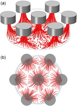
Finite element simulations of t‐RBCs capture trajectory on a 40‐µm diameter and 80‐µm spacing pillars geometry using Comsol 5.3a. (a) side view, (b) top view
In simulations, particles stop at the center of the Ni‐pillars, as on the chip surface a stick condition for the particles was set, to lighten the computational cost of the simulation. Particles are thus unable to diffuse toward higher magnetic field gradient regions, that is, the pillars edges, as experimentally observed.
3.2. Validation of the bovine model
The possibility of optimizing the platform using a bovine model of malaria‐infected blood has been checked by comparing the behavior of t‐RBCs from bovine and human blood in experiments of magnetophoretic capture.
To this scope, we prepared two IBMSs with the same hematocrit (4%; 1:10 dilution factor), corresponding to the sample preparation that we developed for whole blood samples (see Section 2.4 below). The ratio between treated and untreated RBC was 1%, to simulate a typical parasitemia of patients affected by malaria after a fever attack.
Using the experimental setup of Figure 3, and a chip with Ni posts having 40‐µm diameter and 160‐µm spacing, we then measured the capture efficiency as a function of time for the two samples.
Some images of fluorescent t‐RBCs captured by the Ni posts are reported in Figure 6a,b at different magnification. We can observe that t‐RBCs are preferentially captured on one side of the Ni posts, mainly depending on the position of the posts in the stray field produced by the external magnets, which has a non‐negligible in‐plane component for the posts situated out of the vertical symmetry plane of the magnetic stray field (see Figure 3b). As a matter of fact, only in correspondence of said symmetry plane a more uniform filling of the posts is seen.
The curves of the capture efficiency recorded for bovine and human t‐RBCs are reported in Figure 6c with black and red solid lines, respectively. Within the experimental error bar, the two curves are essentially identical, thus indicating that the bovine model is a good model for the investigation of magnetophoretic properties of RBCs from human blood samples. On this basis, the bovine model of malaria‐infected RBC was used throughout the experiments reported below.
3.3. Geometrical optimization of the chip layout
A detailed investigation of the impact of Ni posts geometry, cell height, and external field on capture efficiency was carried out using MSs with t‐RBC volume concentration of 0.02%.
To better understand the experimental results let us first discuss the dynamics of the magnetophoretic capture. According to our protocol, the sample drop is dispensed on the glass slide 30 s before the positioning of the chip with the magnet above it. This time interval, slightly exceeding the time needed for chip manipulation, was kept fixed to start the magnetophoretic capture with the same distribution of RBCs upon sedimentation.
With a typical RBCs sedimentation speed in plasma or PBS of 2–4 µm/s (Bottiger & Svedberg, 1967; Ng, 1997; Saadeh, 1998) and a cell height of 20–40 µm, we thus expect that all RBCs lay at the surface of the glass slide when magnetic capture starts.
Experimentally, we observe that only t‐RBCs within the footprint of a Ni post are immediately attracted. In agreement with the simulations reported above, the t‐RBCs in the regions between Ni posts slowly move toward the closest post, surfing just above the glass slide under the action of the in‐plane component of the magnetic force arising from the stray field of the posts.
Finally, when they enter the footprint of a Ni post, they are captured and lifted, until they stick at the surface of the Ni post. This behavior clearly indicates that the external gradient produced by permanent magnets is not enough to overcome the sedimentation force in the interstitial regions.
There, according to our estimation above, the magnetic force is of the same order of magnitude as sedimentation force, thus reducing the sticking to the surface and favoring the diffusion of each t‐RBC toward the nearest post. Only in the footprint of the Ni post, the vertical component of the magnetic force overcomes gravity, so that posts act as lifts for t‐RBCs.
In Figure 8a, we show the capture efficiency measured for an hcp arrangement of Ni posts with different diameter and spacing. In these comparative experiments, the cell height (δ) was 20 µm and magnets M1, with the lower stray field, were used. Dense arrays (40–80) and (20–80) display the highest capture efficiency, with (40–80) reaching 100% just after 4 min.
Figure 8.

Capture efficiency curves for different combinations of experimental parameters for MSs with 0.02% volume concentration of t‐RBCs. (a) Magnet M1, different geometries, 20 µm gasket, (b) small magnet, different geometries 40 µm gasket, (c) magnet M2, 40 µm gasket, (d) COMSOL simulations, conditions corresponding to (c)
By increasing the spacing to 160 µm, the efficiency decreases, with larger posts (40–160) outperforming smaller ones (20–160). This is easily understood based on the capture mechanism described above: the larger the distance between posts the longer the time needed for RBCs to diffuse toward the nearest post acting as a lift. Nevertheless, the (40–160) geometry still allows reaching an approximate capture efficiency of 80% after 15 min.
By increasing the cell height from 20 to 40 µm (see Figure 8b), the capture efficiency dramatically drops, thus signaling that the magnetic force is highly confined close to the chip surface. The case of (20–160) is no more reported, as it does not yield a sizeable capture efficiency: in this case, the spacing is too large and RBCs in the interstitial regions can hardly reach the nearest post.
A sizeable increase of the capture distance is achieved by improving the magnetic field strength, moving from M1 to M2 external magnets. This is visible in Figure 8c, showing that the use of magnets M2 allows recovering the same capture efficiency measured for δ = 20 µm for the (40–80) and (40–160) geometry, also in case of 40 µm cell height. This is not true for the (20–80) geometry, thus stating a sort of “rule of thumb” for the optimal capture depth, which in our setup is on the order of the post diameter.
For the (20–80) geometry, t‐RBCs at the surface of the glass slide, 40 µm below the chip surface, cannot be attracted by the field gradient produced by Ni posts. By further increasing the cell height up to 60 µm, the capture efficiency essentially drops to zero. Upon the initial sedimentation, RBCs are out of the capture depth.
Experimental data are well replicated by COMSOL simulations, as resulting from the comparison of Figure 8c,d for the case of δ = 40 µm and magnets M2. Both the asymptotic values and the characteristic capture times estimated from simulations of Figure 8d are in good agreement with experimental curves of Figure 8c. In addition, simulations show a capture dynamics with two components. A fast one, with a characteristic time on the order of 1–2 min, and a slower one, which lasts for about 15 min.
As shown in Movie MV1, the slow and fast components correspond to the capture of t‐RBCs that at the initial time lay within the footprint of Ni post and in the interstitial regions, respectively. Despite the reduced number of points arising from the time required for a manual acquisition of data, experimental curves for the capture efficiency show a trace of this behavior, as the first point at 2 min is higher than expected from a single exponential fit of data, particularly for the (40–80) and (40–160) cases.
Due to the peculiar geometry of external magnets, the area of the chip with a magnetic field gradient strong enough to promote magnetophoretic capture of t‐RBCs, roughly corresponds to a stripe with 4 mm width, centered with respect to the mirror plane of the magnet assembly. This is clearly seen in Figure S1, the capture efficiency is peaked around the mirror plane and goes to zero at a lateral distance of 2 mm.
To summarize this section, for 20‐µm‐tall Ni posts, the best conditions for t‐RBCs capture are found for a (40–80) geometry and a cell height not exceeding 40 µm, leading to 100% capture efficiency in 10 min. Good results are also found for the (40–160) geometry, which allows achieving about 80% capture efficiency in 10 min for a cell height of 40 µm.
In the following, we will mainly focus on the last geometry, (40–160), as it represents a good compromise between capture efficiency and detection efficiency. In fact, the largest separation between Ni posts allows taking advantage of the concentration of t‐RBCs on specific sites, where a limited number of detectors could be realized in view of efficient on‐chip capture and detection.
To maximize the capture volume, the cell height was fixed at 40 µm and M2 magnets were used.
3.4. Effect of the matrix and process acceleration by vibration
In a real magnetophoretic separation process, the sedimentation of untreated RBCs can represent a relevant obstacle for the upward motion of i‐RBCs attracted by Ni posts. We investigated this phenomenon by monitoring the dependence of the capture efficiency on the hematocrit of blood samples containing both untreated and treated RBCs.
Different IBMSs were prepared, with increasing HT from 0.4% to 4%, which is the maximum value compatible with our experimental methodology; for higher HT values, the sedimentation of untreated RBCs creates a layer that does not allow distinguishing and counting captured t‐RBC above. The volumetric fraction of t‐RBCs was kept fixed at the value used in experiments of magnetophoretic capture shown in Figure 8 (0.02%).
Figure 9a,b shows the capture efficiency versus time for 0.4% and 4% HT, respectively, measured in a setup with M2 magnets, a cell height of 40 µm, and different lattice geometry for Ni posts.
Figure 9.

Effect of the matrix of u‐RBC on the magnetophoretic capture of t‐RBCs in IBMSs. (a) Total hematocrit of 0.4% and volumetric fraction of fluorescent t‐RBCs of 0.02%, (b) total hematocrit of 4% and volumetric fraction of fluorescent t‐RBCs of 0.02%
The case of 0.4% HT (Figure 9a) is almost identical to that without u‐RBCs, with the (40–80) geometry still allowing reaching 100% capture efficiency.
A slight decrease of the capture efficiency is shown in Figure 9b, for 4% HT, at least for the (40–80) and (40–160) geometries, mainly reflecting the fact that u‐RBCs create a monolayer at the surface of the glass slide, impeding an efficient diffusion of t‐RBCs toward the footprint of Ni posts. The case of the (20–80) geometry is somehow anomalous, because we observe a partial recovery of the capture efficiency at 4% HT with respect to the case of 0.4% HT. This unexpected behavior, observed only for the (20–80) geometry (with a capture depth smaller than cell height), is probably due to t‐RBCs surfing on top of a u‐RBC monolayer formed upon sedimentation. Some t‐RBCs are randomly located closer to the Ni posts (favoring the capture), at variance with the case of 0.4% HT, in which they just sediment at the surface of the glass slide.
To investigate the selectivity of the attraction of t‐RBCs with respect to u‐RBCs, we carried out an experiment of magnetophoretic capture on a noninfected blood model sample, that is, a suspension of stained u‐RBCs, with HT of 4%. The corresponding capture efficiency versus time is shown in Figure 9b with a gray line. The capture is zero during the first 10 min, while at 15 min we see that some u‐RBCs are attracted, thus giving a capture efficiency of a few %. Note, however, that these rare capture events are all associated to the hemolysis of some RBCs close to those that are attracted. After 10 min, the cell membrane of stained RBCs becomes unstable, and we observed the lysis of some RBCs with the delivery of the fluorescent dye to the suspension (see Movie MV2). Immediately after these events, some u‐RBCs, previously unaffected by the magnetic field gradient, started to move toward the Ni pillars till they were eventually captured. We interpret this phenomenon as due to a local decrease of the algebraic magnetic susceptibility of the medium (i.e., to the increase of the magnitude of the diamagnetic susceptibility) upon delivery of the fluorescent dye, finally turning the expected repulsive force on u‐RBCs into an attractive force, due to a change of sign of the relative magnetic susceptibility of the u‐RBCs with respect to the medium.
Overall, our experiments indicate up to 80% selectivity of the magnetophoretic capture of t‐RBC with respect to untreated ones within the first 10 min, while the nonspecific attraction of u‐RBCs taking place after 10 min seems to be an extrinsic phenomenon induced by the staining with the fluorescent dye. This is crucial, because a high selectivity capture is a prerequisite for the implementation of a diagnostic test for Malaria with high specificity, associated to a low percentage of false positives.
Finally, let us consider the effect of vibration during capture. Due to the peculiar capture process, involving a slow lateral motion of RBCs toward the pillars footprint followed by a vertical capture, a suitable sample agitation can improve the rapidity of the capture.
By tuning the amplitude and timing of the driving voltage of an eccentric motor (C1026B by Parallax Inc.) stuck on the magnet assembly to produce mainly a vertical vibration, we found that the best condition corresponds to a periodic agitation. In each period, we first keep the agitation at a low value (driving signal A1 = 1.55 V) for 1.5 s and then we increase the driving signal up to A2 = 1.8 V for just 0.4 s. In the first phase, a small vibration is applied to speed up the capture of t‐RBCs already sitting in the capture footprint of a Ni pillar, while in the second one a larger vibration allows to detach RBCs from the glass slide and resuspend them, thus promoting the lateral motion toward the Ni pillars.
As above, IBMSs were prepared keeping the volume percentage of t‐RBCs fixed at 0.02%, thus allowing for an easy evaluation of the capture efficiency by optical investigation. After just 5 min, 95% capture efficiency was achieved in case of a 0.4% HT, while efficiency decreases to 85% in case of a 4% HT. These values represent an improvement with respect to the 75% efficiency achieved in static conditions, both for 0.4% and 4% HT (see Figure 9), thus pointing to the possibility of achieving large capture efficiency of RBC infected by malaria in just 5 min with our on‐chip system. More details of the results obtained with capture under vibration are reported in Section S2 and Figure S2.
3.5. Selective capture of t‐RBCs in whole blood samples
To check the compatibility of our method with a simple sample preparation procedure, we prepared some samples with an HT = 4%, and t‐RBCs volume percentage of 0.02% (0.5% equivalent parasitemia) just by diluting fresh bovine blood treated with heparin in PBS (1:10) and adding stained t‐RBCs from another blood sample.
At variance with previous experiments, here the buffy coat, made of white blood cells and platelets, was not removed. In this way, we simulated the case of a real test from a blood drop of a patient affected by malaria, requiring just a blood dilution in heparin and PBS to facilitate the movement of i‐RBCs in the sea of healthy RBCs, white blood cells, and platelets.
The capture efficiency curves versus time in static conditions, (40–160) geometry, 40 µm cell height, and M2 magnets, are reported in Figure 10, for tests carried out after 3 or 7 h since blood collection.
Figure 10.

Capture efficiency of stained t‐RBCs and u‐RBCs, corresponding to the 0.5% of the total number of RBCs in the sample (0.02% volumetric fraction over the whole sample), suspended in whole blood diluted (1:10) in PBS and heparin to obtain a 4% hematocrit
At three hours since blood collection (red solid line), we obtain a capture efficiency of 70% in 10 min after the dispensation of blood on the glass slide. This value is only slightly lower than the 80% found in static conditions for IBMSs, if we take into account the error bars of our experimental evaluations.
Seven hours after blood collection (dashed black line), we observe a small decrease of the average capture efficiency, down to about 52% at 10 min, which might be due to the action of platelets, not inhibited by heparin, forming initial clotting filaments which impede the free movement of RBCs. In the same conditions, we also tested the system for nonspecific attraction, by measuring the capture efficiency (blue curve in Figure 10) of a sample prepared as above, with the sole difference of adding stained u‐RBCs. In this case, the capture efficiency is zero up to 10 min from the beginning of the experiment, thus displaying a behavior like that seen in Figure 9b.
High capture efficiency and a negligible rate of nonspecific capture are thus observed, also in case of a very simple blood preparation by dilution with heparin and PBS.
4. CONCLUSIONS
In this study, we focused on a systematic characterization and optimization of the separation efficiency of our lab‐on‐chip device. The main limitation of our study is related to the use of t‐RBCs as a model of malaria‐infected RBCs. Switching to real i‐RBCs is expected to bring about additional practical issues, which we ignored in this study. For instance, especially at the early ring stage of infection, the quantities of hemozoin nanocrystals produced by the parasites are variable, and may affect the resulting magnetization of i‐RBCs. Indeed, we previously showed that the magnetophoretic capture of ring‐stage i‐RBCs does occur, but may imply a slower dynamics than the capture of trophozoites (Giacometti et al., 2021). Earlier works exploiting magnetophoretic capture under flow also demonstrated different capture capabilities of the same magnetic‐based setting for different‐stage i‐RBCs, with the ring stage representing the most difficult stage to be detected (Karl et al., 2008). Here, for the purpose of repeatability, we kept the i‐RBC model rigorously unchanged throughout our experiments. Indeed, our main focus was to systematically characterize the capture efficiency as a function of the intrinsic chip design features and measurement protocol, rather than the effect of extrinsic factors related to the variability of biological samples.
Design guidelines were set in the perspective of making the system suitable for low resource settings. The need for a low production cost pushed us toward the adoption of standard manufacturing techniques, thus accepting some limitations, which could be overcome with more sophisticated techniques, but higher costs. Other choices, such as avoiding complicated sample preparation and using flow‐less fluidics, pointed toward making the system suitable for use with minimal user training. Further exploitation to implement a diagnostic test for malaria requires integrating i‐RBCs counting, in a way suitable for low‐cost, rapid, and on‐site wide screening of the population in endemic zones. In our strategy (Giacometti et al., 2021; Milesi et al., 2020), we are implementing this via integrated electrical sensors placed close to the concentrating elements of the chip. However other sensor strategies might be used (e.g., magnetic and optical), as well as resorting to automated pattern recognition of optical images at the focal plane of the chip attraction points. Concerning other possible applications, malaria research is active in a large number of well‐funded laboratories around the world, where separation of infected from uninfected cells, or counting the number of infected cells, are performed on a daily basis. Our new technique might find application as a low‐cost automated technique in such research environments.
Supporting information
Supporting information.
Supporting information.
Supporting information.
ACKNOWLEDGMENTS
The authors acknowledge the support of Politecnico di Milano via the Polisocial Awards program 2016, project Tid Mekii, as well from the Switch to Product “Disruptive innovation award” 2018. The authors acknowledge funding from the European Research Council (ERC) under the European Union's Horizon 2020 Research and Innovation Program (G.A. no. 646990 – NICHOID). All the authors thank A. Dimasi, M. Tunesi, L. Livietti, and M. Corbellino for experimental support and fruitful discussions. This study was partially performed at Polifab, the micro‐ and nano‐fabrication facility of Politecnico di Milano and at the Interdepartmental lab for Live Cell Imaging (LuCId Lab) of Politecnico di Milano. Open access funding provided by Politecnico di Milano within the CRUI‐CARE Agreement.
Giacometti, M. , Monticelli, M. , Piola, M. , Milesi, F. , Coppadoro, L. P. , Giuliani, E. , Jacchetti, E. , Raimondi, M. T. , Ferrari, G. , Antinori, S. , Fiore, G. B. , & Bertacco, R. (2022). On‐chip magnetophoretic capture in a model of malaria‐infected red blood cells. Biotechnology and Bioengineering, 119, 1129–1141. 10.1002/bit.28030
Contributor Information
Gianfranco B. Fiore, Email: gianfranco.fiore@polimi.it.
Riccardo Bertacco, Email: riccardo.bertacco@polimi.it.
DATA AVAILABILITY STATEMENT
The data that support the findings of this study are available from the corresponding author upon reasonable request.
REFERENCES
- Bertacco, R. , Petti, D. , Ferrari, G. , Albisetti, E. , & Giacometti, M. (2017). Device and method for the quantification of cellular and non‐cellular blood components. Ital. Pat. n. 102017000082112.
- Bertacco, R. , Fiore, G. B. , Ferrari, G. , Giacometti, M. , Milesi, F. , Coppadoro, L. P. & Giuliani, E. (2019). Apparato per la quantificazione di componenti biologiche disperse in un fluido. Ital. Pat. n. 102019000000821.
- Blue Martin, A. , Wu, W.‐T. , Kameneva, M. V. , & Antaki, J. F. (2017). Development of a high‐throughput magnetic separation device for malaria‐infected erythrocytes. Annual Review of Biomedical Engineering, 45, 2888–2898. http://link.springer.com/10.1007/s10439-017-1925-2 [DOI] [PMC free article] [PubMed] [Google Scholar]
- Bottiger, L. E. , & Svedberg, C. A. (1967). Normal erythrocyte sedimentation rate and age. BMJ, 2, 85–87. https://www.bmj.com/lookup/doi/10.1136/bmj.2.5544.85 [DOI] [PMC free article] [PubMed] [Google Scholar]
- Cohen, J. M. , Smith, D. L. , Cotter, C. , Ward, A. , Yamey, G. , Sabot, O. J. , & Moonen, B. (2012). Malaria resurgence: A systematic review and assessment of its causes. Malaria Journal, 11, 122. https://malariajournal.biomedcentral.com/articles/10.1186/1475-2875-11-122 [DOI] [PMC free article] [PubMed] [Google Scholar]
- Fiore, G. B. , Guadagni, G. , Lupi, A. , Ricci, Z. , & Ronco, C. (2006). A new semiempirical mathematical model for prediction of internal filtration in hollow fiber hemodialyzers. Blood Purification, 24, 555–568. https://www.karger.com/Article/FullText/97079 [DOI] [PubMed] [Google Scholar]
- Giacometti, M. , Rinaldi, C. , Monticelli, M. , Callegari, L. , Collovini, A. , Petti, D. , Ferrari, G. , & Bertacco, R. (2018). Electrical and magnetic properties of hemozoin nanocrystals. Applied Physics Letters, 113, 203703. http://aip.scitation.org/doi/10.1063/1.5050062 [Google Scholar]
- Giacometti, M. , Milesi, F. , Coppadoro, P. L. , Rizzo, A. , Fagiani, F. , Rinaldi, C. , Cantoni, M. , Petti, D. , Albisetti, E. , Sampietro, M. , Ciardo, M. , Siciliano, G. , Alano, P. , Lemen, B. , Bombe, J. , Nwaha Toukam, M. T. , Tina, P. F. , Gismondo, M. R. , Corbellino, M. , … Bertacco, R. (2021). A lab‐on‐chip tool for rapid, quantitative, and stage‐selective diagnosis of malaria. Advanced Science, 8, 2004101. https://onlinelibrary.wiley.com/doi/10.1002/advs.202004101 [DOI] [PMC free article] [PubMed] [Google Scholar]
- Greenwald, R. A. (2018). Handbook methods for oxygen radical research. CRC Press. [Google Scholar]
- Grimberg, B. T. , & Grimberg, K. O. (2016). Hemozoin detection may provide an inexpensive, sensitive, 1‐minute malaria test that could revolutionize malaria screening. Expert Review of Anti‐Infective Therapy, 14, 879–883. https://www.tandfonline.com/doi/full/10.1080/14787210.2016.1222900 [DOI] [PMC free article] [PubMed] [Google Scholar]
- Gupta, H. , Matambisso, G. , Galatas, B. , Cisteró, P. , Nhamussua, L. , Simone, W. , Cunningham, J. , Rabinovich, N. R. , Alonso, P. , Saute, F. , Aide, P. , & Mayor, A. (2017). Molecular surveillance of pfhrp2 and pfhrp3 deletions in Plasmodium falciparum isolates from Mozambique. Malaria Journal, 16, 416. https://malariajournal.biomedcentral.com/articles/10.1186/s12936-017-2061-z [DOI] [PMC free article] [PubMed] [Google Scholar]
- Han, K. ‐H. , & Bruno Frazier, A. (2004). Continuous magnetophoretic separation of blood cells in microdevice format. Journal of Applied Physics, 96, 5797–5802. http://aip.scitation.org/doi/10.1063/1.1803628 [Google Scholar]
- Han, K. ‐H. , & Frazier, A. B. (2006). Paramagnetic capture mode magnetophoretic microseparator for high efficiency blood cell separations. Lab on a Chip, 6, 265–273. http://xlink.rsc.org/?DOI=B514539B [DOI] [PubMed] [Google Scholar]
- Hänscheid, T. , Egan, T. J. , & Grobusch, M. P. (2007). Haemozoin: From melatonin pigment to drug target, diagnostic tool, and immune modulator. The Lancet Infectious Diseases, 7, 675–685. https://linkinghub.elsevier.com/retrieve/pii/S1473309907702384 [DOI] [PubMed] [Google Scholar]
- Karl, S. , David, M. , Moore, L. , Grimberg, B. T. , Michon, P. , Mueller, I. , Zborowski, M. , & Zimmerman, P. A. (2008). Enhanced detection of gametocytes by magnetic deposition microscopy predicts higher potential for Plasmodium falciparum transmission. Malaria Journal, 7, 1–9. [DOI] [PMC free article] [PubMed] [Google Scholar]
- Kasetsirikul, S. , Buranapong, J. , Srituravanich, W. , Kaewthamasorn, M. , & Pimpin, A. (2016). The development of malaria diagnostic techniques: A review of the approaches with focus on dielectrophoretic and magnetophoretic methods. Malaria Journal, 15, 358. http://malariajournal.biomedcentral.com/articles/10.1186/s12936-016-1400-9 [DOI] [PMC free article] [PubMed] [Google Scholar]
- Keszler, A. , Piknova, B. , Schechter, A. N. , & Hogg, N. (2008). The reaction between nitrite and oxyhemoglobin. Journal of Biological Chemistry, 283, 9615–9622. https://linkinghub.elsevier.com/retrieve/pii/S0021925820570324 [DOI] [PMC free article] [PubMed] [Google Scholar]
- Kim, J. , Massoudi, M. , Antaki, J. F. , & Gandini, A. (2012). Removal of malaria‐infected red blood cells using magnetic cell separators: A computational study. Applied Mathematics and Computation, 218, 6841–6850. https://linkinghub.elsevier.com/retrieve/pii/S009630031101544X [DOI] [PMC free article] [PubMed] [Google Scholar]
- Lucchi, N. W. , Gaye, M. , Diallo, M. A. , Goldman, I. F. , Ljolje, D. , Deme, A. B. , Badiane, A. , Ndiaye, Y. D. , Barnwell, J. W. , Udhayakumar, V. , & Ndiaye, D. (2016). Evaluation of the illumigene malaria LAMP: A robust molecular diagnostic tool for malaria parasites. Scientific Reports, 6, 1–8. 10.1038/srep36808 [DOI] [PMC free article] [PubMed] [Google Scholar]
- Mata‐Cantero, L. , Lafuente, M. J. , Sanz, L. , & Rodriguez, M. S. (2014). Magnetic isolation of Plasmodium falciparum schizonts iRBCs to generate a high parasitaemia and synchronized in vitro culture. Malaria Journal, 13, 112. https://malariajournal.biomedcentral.com/articles/10.1186/1475-2875-13-112 [DOI] [PMC free article] [PubMed] [Google Scholar]
- Matteucci, M. J. , Reed, W. J. , & Tanen, D. A. (2003). Sodium thiosulfate fails to reduce nitrite‐induced methemoglobinemia in vitro. Academic Emergency Medicine, 10, 299–302. https://onlinelibrary.wiley.com/doi/10.1111/j.1553-2712.2003.tb01339.x [DOI] [PubMed] [Google Scholar]
- Milesi, F. , Giacometti, M. , Coppadoro, L. P. , Ferrari, G. , Fiore, G. B. , & Bertacco, R. (2020). On‐chip selective capture and detection of magnetic fingerprints of malaria. Sensors, 20, 4972. https://www.mdpi.com/1424-8220/20/17/4972 [DOI] [PMC free article] [PubMed] [Google Scholar]
- Nature . (2018). Pay people to fight malaria. Nature, 559, 443. http://www.nature.com/articles/d41586-018-05799-2 [DOI] [PubMed] [Google Scholar]
- Ng, T. (1997). Erythrocyte sedimentation rate, plasma viscosity and C‐reactive protein in clinical practice. British Journal of Hospital Medicine, 58, 521–523. http://www.ncbi.nlm.nih.gov/pubmed/10193457 [PubMed] [Google Scholar]
- Noland, G. S. , Briones, N. , & Sullivan, D. J. (2003). The shape and size of hemozoin crystals distinguishes diverse Plasmodium species. Molecular and Biochemical Parasitology, 130, 91–99. https://linkinghub.elsevier.com/retrieve/pii/S0166685103001634 [DOI] [PubMed] [Google Scholar]
- Ribaut, C. , Berry, A. , Chevalley, S. , Reybier, K. , Morlais, I. , Parzy, D. , Nepveu, F. , Benoit‐Vical, F. , & Valentin, A. (2008). Concentration and purification by magnetic separation of the erythrocytic stages of all human Plasmodium species. Malaria Journal, 7, 45. https://malariajournal.biomedcentral.com/articles/10.1186/1475-2875-7-45 [DOI] [PMC free article] [PubMed] [Google Scholar]
- Roberts, L. (2016). Malaria wars. Science (80‐.), 352, 398–405. https://www.science.org/doi/10.1126/science.352.6284.398 [DOI] [PubMed] [Google Scholar]
- Rodkey, F. L. (1976). A mechanism for the conversion of oxyhemoglobin to methemoglobin by nitrite. Clinical Chemistry, 22, 1986–1990. http://www.ncbi.nlm.nih.gov/pubmed/11898 [PubMed] [Google Scholar]
- Saadeh, C. (1998). The erythrocyte sedimentation rate: Old and new clinical applications. Southern Medical Journal, 91, 219–226. http://content.wkhealth.com/linkback/openurl?sid=WKPTLP:landingpage%26an=00007611-199803000-00001 [PubMed] [Google Scholar]
- Sumari, D. , Grimberg, B. T. , Blankenship, D. , Mugasa, J. , Mugittu, K. , Moore, L. , Gwakisa, P. , & Zborowski, M. (2016). Application of magnetic cytosmear for the estimation of Plasmodium falciparum gametocyte density and detection of asexual stages in asymptomatic children. Malaria Journal, 15, 1–9. [DOI] [PMC free article] [PubMed] [Google Scholar]
- WHO . (2017). World malaria report 2017.
- WHO . (2018). World malaria report 2018.
- Yerlikaya, S. , Campillo, A. , & Gonzalez, I. J. (2018). A systematic review: Performance of rapid diagnostic tests for the detection of Plasmodium knowlesi, Plasmodium malariae, and Plasmodium ovale monoinfections in human blood. Journal of Infectious Diseases, 218, 265–276. https://academic.oup.com/jid/article/218/2/265/4938977 [DOI] [PMC free article] [PubMed] [Google Scholar]
- Zijlstra, W. G. , & Buursma, A. (1997). Spectrophotometry of hemoglobin: Absorption spectra of bovine oxyhemoglobin, deoxyhemoglobin, carboxyhemoglobin, and methemoglobin. Comparative Biochemistry and Physiology Part B: Biochemistry & Molecular Biology, 118, 743–749. [Google Scholar]
- Zimmerman, P. A. , Thomson, J. M. , Fujioka, H. , Collins, W. E. , & Zborowski, M. (2006). Diagnosis of malaria by magnetic deposition microscopy. American Journal of Tropical Medicine and Hygiene, 74, 568–572. [PMC free article] [PubMed] [Google Scholar]
Associated Data
This section collects any data citations, data availability statements, or supplementary materials included in this article.
Supplementary Materials
Supporting information.
Supporting information.
Supporting information.
Data Availability Statement
The data that support the findings of this study are available from the corresponding author upon reasonable request.