

Abstract

The high design flexibility of organic semiconductors should lead to diverse and complex electronic functions. However, currently available high-performance organic semiconductors are limited in variety; most of p-type materials are based on thienoacenes or related one-dimensionally (1D) extended π-conjugated systems. In an effort to expand the diversity of organic semiconductors, we are working on the development of tetrabenzoporphyrin (BP) derivatives as active-layer components of organic electronic devices. BP is characterized by its large, rigid two-dimensionally (2D) extended π-framework with high light absorptivity and therefore is promising as a core building unit of organic semiconductors for optoelectronic applications. Herein, we demonstrate that BP derivatives can afford field-effect hole mobilities of >4 cm2 V–1 s–1 upon careful tuning of substituents. Comparative analysis of a series of 5,15-bis(n-alkyldimethylsilylethynyl)tetrabenzoporphyrins reveals that linear alkyl substituents disrupt the π–π stacking of BP cores, unlike the widely observed “fastener effect” for 1D extended π-systems. The n-octyl and n-dodecyl groups have the best balance between high solution processability and minimal π–π stacking disruption, leading to superior hole mobilities in solution-processed thin films. The resulting thin films show high thermal stability wherein the field-effect hole mobility stays above 1 cm2 V–1 s–1 even after heating at 160 °C in air, reflecting the tight packing of large BP units. These findings will serve as a good basis for extracting the full potential of 2D extended π-frameworks and thus for increasing the structural or functional diversities of high-performance organic semiconductors.
Keywords: organic semiconductors, organic transistors, tetrabenzoporphyrin, molecular packing, substituent engineering
Introduction
The charge-carrier mobility in organic field-effect transistors (OFETs) has improved rapidly in the past few decades owing to the synergistic advancement in molecular design and deposition techniques of organic semiconductors.1−7 The progress has led to high charge-carrier mobilities over 10 cm2 V–1 s–1, opening up the possibility of film-based products comprising organic circuits.8−11 However, only limited classes of π-conjugated systems, mostly thienoacenes, have been observed to achieve such high mobilities so far.1,2,12−14 The expansion of the material scope is of great significance; the high design flexibility of organic materials lends itself to diverse and complex electronic functions.
Tetrabenzoporphyrin (BP) features a two-dimensionally (2D) extended π-conjugated framework composed of 40 nonhydrogen atoms. This large, rigid framework is ideal for forming tight π-stacking that enables swift charge-carrier transport. BP is also a strong visible light absorber with a molar absorptivity as high as 105 M–1 cm–1, and its electronic structure is easy to modify through facile complexation with a variety of metal ions.15−17 These characteristics make BP an intriguing building unit of organic semiconductors. Nonetheless, it remains underrepresented in organic electronics owing largely to the limited availability of soluble derivatives and the lack of an effective packing-control methodology, rather than due to any intrinsic problem regarding its electronic properties.
In consideration of the above background, we are designing solution-processable BP derivatives and evaluating their potentials as active-layer materials in OFETs. One of the previously reported derivatives, named TIPS-BP (Chart 1), was found to stack in a brickwork motif associated with effective π–π contacts under carefully optimized deposition conditions.18 The resulting films showed field-effect hole motilities (μh) of up to 1.1 cm2 V–1 s–1, which far exceeds the previous records of 0.070 and 0.25 cm2 V–1 s–1 for free-base and metal-incorporated BPs, respectively.19,20 Based on this encouraging result, the present work seeks to further elaborate the molecular structure through careful evaluation of alkyl group effects on the solid-state packing of BP frameworks toward achieving even higher hole mobilities.
Chart 1. Chemical Structures of the BP Derivatives Compared Hereina.

a TIPS-BP was reported previously,18 while the other derivatives are newly synthesized in this work.
Introduction of long alkyl chains is often an effective approach for tightening molecular packing, thereby improving charge-carrier mobility in organic semiconductors. This effect is due to the alkyl–alkyl van der Waals interaction, often referred to as the “fastener effect” or “zipper effect”. For example, Takimiya and co-workers reported that the hole mobility in vacuum-deposited films of alkylated dinaphtho[2,3-b:2′,3′-f]thieno[3,2-b]thiophenes (Cn-DNTTs) increased with elongation of alkyl substituents from n-hexyl (C6-DNTT) to n-octyl (C8-DNTT) and to n-decyl (C10-DNTT).21 Alkyl substituents also affect other critical characteristics of organic semiconductors such as solution processability and molecular packing motif (e.g., brickwork vs herringbone). These alkyl group effects are generally subtle and hard to predict; therefore, molecular design of organic semiconductors often involves experimental screening of structures and positions of alkyl substituents.1,22−24
Herein, we explore alkyl group effects on 5,15-bis(trialkylsilylethynyl)tetrabenzoporphyrins. The effects may appear in an atypical manner because the BP framework is structurally dissimilar to well-studied π-conjugated systems. Specifically, the BP framework is (1) 2D extended, while previous examples are mostly one-dimensional (1D) (either straight or bent); (2) considerably larger (40 nonhydrogen atoms) than commonly employed π-frameworks (e.g., 22 for pentacene, 24 for DNTT, and 30 for perylene diimide); and (3) fully edged with hydrogen atoms without any exposed heteroelements such as sulfur and oxygen that often play key roles in intermolecular interactions. In fact, this work reveals that long alkyl chains attenuate, rather than enhance, the π-stacking of BP units. Yet, hole mobilities of up to 4.1 cm2 V–1 s–1 are obtained, which is a significant improvement from 1.1 cm2 V–1 s–1 in TIPS-BP. The following sections describe the design, packing, and charge-carrier transport characteristics of nine new BP derivatives named C8DIPS-BP, CxDMS-BP, and CxDMS-CuBP (x = 4, 8, 12, or 16; Chart 1). A comparison of CxDMS-BP and CxDMS-CuBP demonstrates unconventional aspects of alkyl group effects, extending the basis of molecular design for organic semiconductors.
Results and Discussion
Molecular Design
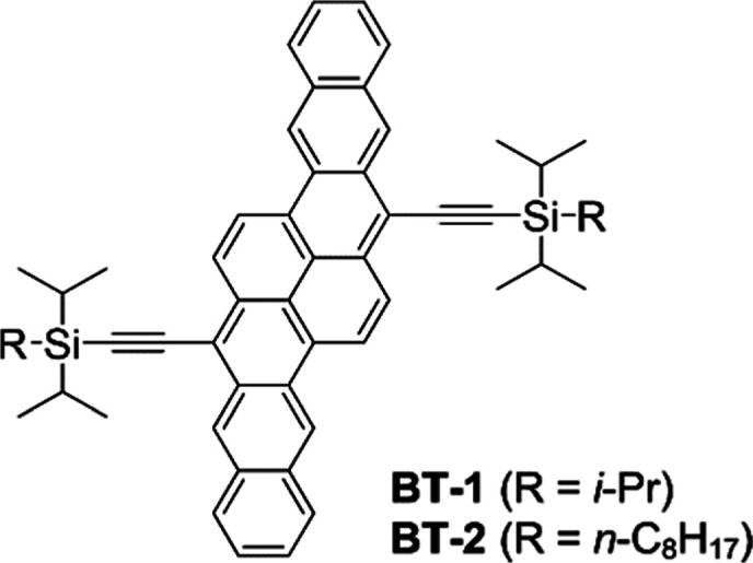
C8DIPS-BP, the first BP derivative examined in this work, has two diisopropyl(n-octyl)silyl (C8DIPS) groups (Chart 1). This compound is a simple modification of TIPS-BP, and its molecular design is inspired by the 2014 paper by Zhang and co-workers.25 They compared the two bispentacene derivatives, BT-1 and BT-2 (Chart 2), and found that BT-1 with triisopropyl groups showed only moderate hole mobilities of up to 0.4 cm2 V–1 s–1, while BT-2 with C8DIPS groups afforded 6.1 cm2 V–1 s–1 in single-crystal OFETs. The higher performance of BT-2 was ascribed to tighter π-stacking induced by the intermolecular van der Waals interaction between n-octyl groups (i.e., the fastener effect). However, the same effect was not observed in the present case of C8DIPS-BP. The hole mobility in solution-deposited C8DIPS-BP was only 0.081 cm2 V–1 s–1 at best, significantly lower than those in solution-deposited and single-crystalline TIPS-BP (μh = 1.1 and 2.2 cm2 V–1 s–1, respectively18,26). Examination of the single-crystal X-ray structure revealed that the two C8DIPS groups severely hinder the π–π contact between BP units, despite the larger size of the BP framework than that of BT (40 vs 32 nonhydrogen atoms). This observation is yet another example demonstrating that structural details of π-frameworks such as aspect ratios and substituent positions have significant effects on the resulting molecular packing. A more detailed discussion regarding the molecular packing of C8DIPS-BP is provided in the Supporting Information.
Chart 2. Chemical Structures of BT-1 and BT-2 Reported by Zhang et al25.
We next replaced the C8DIPS groups in C8DIPS-BP with dimethyl(n-octyl)silyl (C8DMS), expecting a more effective stacking of BP units owing to the reduced steric demand of substituents. Here, we kept the trialkylsilylethynyl motif and did not try directly alkylated structures because the extrusion of alkyl chains from the BP plane near its center can significantly impede the π–π stacking between BP cores. Gratifyingly, the resulting derivative C8DMS-BP turned out to afford a much higher hole mobility than that of C8DIPS-BP (vide infra). The energy levels and distribution of the frontier molecular orbitals are expected to be essentially unaltered upon the change of alkyl groups (Figure S3 in the Supporting Information). Then, we decided to investigate the effects of alkyl groups on C8DMS-BP and its variants with different alkyl chain lengths, namely, the CxDMS-BP family (x = 4, 8, 12, or 16; Chart 1). Additionally, the corresponding Cu(II) complexes, CxDMS-CuBP, were evaluated to study the impact of the metal ion on molecular packing and carrier-transport efficiency. Note that CuBP afforded the highest hole mobility among the nonsubstituted free-base BPs and their metal complexes examined so far.20
Synthesis
CxDMS-BP and CxDMS-CuBP were prepared via soluble precursors in order to avoid direct chemical modification of hardly soluble BP (Scheme 1). The synthesis was started with the acid-catalyzed “2 + 2” condensation cyclization of dipyrromethane 1 and 3-(n-alkyldimethylsilyl)-2-propynal (Cx-2), followed by oxidation with 2,3-dichloro-5,6-dicyano-1,4-benzoquinone. The thus-obtained thermal precursors (CxDMS-CP) were quantitatively transformed to the target CxDMS-BP by heating at 200 °C under vacuum in the solid state. The Cu(II) complexes, CxDMS-CuBP, were synthesized by reacting CxDMS-CP with Cu(OAc)2 and then heating. Detailed synthetic procedures are provided in the Supporting Information with the corresponding spectroscopic characterization data.
Scheme 1. Synthesis of CxDMS-BP and CxDMS-CuBP (x = 4, 8, 12, or 16).

Hole Mobility in Solution-Processed Films
The newly synthesized BP derivatives were evaluated for hole transport capability in OFETs of the bottom-gate-top-contact structure. Each derivative was deposited by dip-coating on a silicon substrate having a SiO2/Al2O3 dielectric layer modified with 12-cyclohexyldodecylphosphonic acid (see the Supporting Information for the details of device fabrication and measurements).27 The ionization energies of the resulting films are very similar within a small range between 4.8 and 5.0 eV (Figure S4 in the Supporting Information), which are close to the corresponding value for TIPS-BP (4.9 eV).18 The obtained FET parameters are summarized in Table 1, while the transfer [drain current–gate voltage (ID–VG)] curves of the best-performing devices are shown in Figure 1. The corresponding output [drain current–drain voltage (ID–VD)] curves and the gate-voltage dependency of hole mobility are shown in Figures S5 and S6 in the Supporting Information.
Table 1. FET Characteristics of CxDMS-BP and CxDMS-CuBP (x = 4, 8, 12, or 16).
| compound | μh (cm2 V–1 s–1)a | Vth (V)b | Ion/Ioffc | compound | μh (cm2 V–1 s–1)a | Vth (V)b | Ion/Ioffc |
|---|---|---|---|---|---|---|---|
| C4DMS-BP | 0.12 (0.098 ± 0.021) | –3.0 | 1.8 × 10⁴ | C4DMS-CuBP | 0.034 (0.014 ± 0.008) | –7.5 | 1.9 × 10⁴ |
| C8DMS-BP | 2.7 (2.5 ± 0.3) | –7.3 | 3.6 × 10⁵ | C8DMS-CuBP | 4.1 (3.3 ± 0.7) | –4.3 | 1.8 × 10⁵ |
| C12DMS-BP | 3.4 (2.1 ± 0.7) | –5.1 | 2.1 × 10⁴ | C12DMS-CuBP | 4.1 (2.8 ± 0.9) | –1.6 | 7.9 × 10⁴ |
| C16DMS-BP | 2.3 (1.8 ± 0.3) | 4.9 | 1.7 × 10⁴ | C16DMS-CuBP | 3.0 (2.0 ± 0.5) | 5.9 | 1.6 × 10⁴ |
Hole mobility of the best-performing device followed by an average of eight devices in parentheses.
Threshold voltage of the best-performing device.
On–off current ratio of the best-performing device determined from the ID–VG curve.
Figure 1.

Transfer characteristics of the best-performing FETs based on (a) C4DMS-BP, (b) C8DMS-BP, (c) C12DMS-BP, (d) C16DMS-BP, (e) C4DMS-CuBP, (f) C8DMS-CuBP, (g) C12DMS-CuBP, and (h) C16DMS-CuBP. VD = −50 V, channel length (L) = 0.15 mm, channel width (W) = 1.0 mm.
C12DMS-BP performed the best among the four free-base derivatives, affording a hole mobility of 3.4 cm2 V–1 s–1. This value is 3 times higher than that in TIPS-BP (μh = 1.1 cm2 V–1 s–1).18 C8 and C16DMS-BP also showed higher mobilities (μh = 2.7 and 2.3 cm2 V–1 s–1, respectively) than TIPS-BP. C4DMS-BP was an exception, in which the hole mobility is 1 order lower (μh = 0.12 cm2 V–1 s–1) as compared to that of the other free-base derivatives. This dependency of hole mobility on the alkyl chain length was qualitatively reproduced, while the difference between the best and worst cases became more pronounced, with the Cu(II) complexes. Specifically, the hole mobility was highest in C8 and C12DMS-CuBP (μh = 4.1 cm2 V–1 s–1) and somewhat lower in C16DMS-CuBP (μh = 3.0 cm2 V–1 s–1). These values exceed those in the corresponding free-base derivatives. By contrast, C4DMS-CuBP showed a hole mobility of only 0.034 cm2 V–1 s–1 at best, which is even lower than that observed in its free-base counterpart.
Molecular Packing in Single Crystals
To understand the difference among the observed hole mobilities, we studied molecular packing of the BP derivatives in the single crystalline state. Single crystals of C4-, C8-, and C12DMS-BP and C4- and C8DMS-CuBP were successfully grown and subjected to X-ray diffraction (XRD) analysis. However, the other derivatives did not form single crystals suitable for measurement despite multiple trials. The corresponding crystallographic parameters and data are summarized in Table 2, and ellipsoid plots of molecules are shown in Figure S7 of the Supporting Information.
Table 2. Single-Crystal XRD Parameters and Crystal Data.
| C4DMS-BP | C8DMS-BP | C12DMS-BP | C4DMS-CuBP | C8DMS-CuBP | |
|---|---|---|---|---|---|
| formula | C52H50N4Si2 | C60H66N4Si2 | C68H82N4Si2 | C52H48CuN4Si2 | C60H64CuN4Si2 |
| formula weight | 787.14 | 899.34 | 1011.55 | 848.66 | 960.87 |
| crystal system | triclinic | triclinic | monoclinic | monoclinic | triclinic |
| space group | P1̅ | P1̅ | C2/c | P2/c | P1̅ |
| a (Å) | 6.351(2) | 6.3032(6) | 59.75(8) | 21.09(2) | 6.340(6) |
| b (Å) | 15.504(6) | 15.5973(12) | 6.089(9) | 6.364(7) | 15.418(16) |
| c (Å) | 21.440(8) | 26.577(2) | 16.01(2) | 15.447(18) | 26.10(3) |
| α (deg) | 101.342(7) | 74.162(7) | 90 | 90 | 74.409(13) |
| β (deg) | 91.782(7) | 88.433(8) | 91.128(15) | 102.140(18) | 89.107(18) |
| γ (deg) | 90.828(7) | 88.927(7) | 90 | 90 | 89.070(16) |
| V (Å3) | 2068.3(13) | 2512.6(4) | 5824(14) | 2027(4) | 2457(4) |
| Z | 2 | 2 | 4 | 2 | 2 |
| T (K) | 90 | 90 | 90 | 90 | 90 |
| crystal size (mm3) | 0.30 × 0.15 × 0.03 | 0.20 × 0.20 × 0.01 | 0.20 × 0.20 × 0.01 | 0.20 × 0.05 × 0.01 | 0.20 × 0.10 × 0.005 |
| 2θmin, 2θmax (deg) | 2.98, 50.28 | 3.19, 49.00 | 4.09, 48.57 | 3.95, 48.40 | 2.74, 49.00 |
| reflections collected | 11104 | 12867 | 12028 | 8608 | 11780 |
| independent reflections | 7284 (Rint = 0.0452) | 8282 (Rint = 0.1013) | 4676 (Rint = 0.3216) | 3262 (Rint = 0.2036) | 8077 (Rint = 0.0896) |
| R1, wR2 (all data) | 0.1063, 0.1961 | 0.2095, 0.3379 | 0.3334, 0.3048 | 0.2192, 0.3223 | 0.2213, 0.3152 |
| R, wR [I > 2σ(I)] | 0.0716, 0.1734 | 0.1204, 0.2833 | 0.0919, 0.1912 | 0.1265, 0.2811 | 0.1196, 0.2554 |
| GOF on F2 | 1.073 | 1.043 | 0.969 | 1.349 | 1.023 |
| largest diff. peak and hole (e Å–3) | 0.957, −0.445 | 0.686, −0.745 | 0.202, −0.159 | 1.097, −1.943 | 3.229, −1.277 |
| CCDC number | 2089174 | 2032885 | 2089173 | 2032883 | 2089172 |
The five crystal structures are all similar in that BP units are arranged in a herringbone motif (Figure 2). The BP frameworks have considerable face-to-face overlaps, forming π-stack columns similar to those in rubrene rather than in pentacene;28 thus, large anisotropy in charge-carrier mobility is expected for these crystals.29 Similar molecular packings were observed for 5,15-bis(trimethylsilylethynyl)tetrabenzoporphyrin (TMS-BP) and its Cu(II) complex (TMS-CuBP),16 showing that replacing one methyl group in the trimethylsilyl moiety with a linear alkyl chain does not significantly alter the overall packing pattern of BP units. On the other hand, TIPS-BP and C8DIPS-BP formed parallel π-stack (brickwork or lamellar) motifs (see ref (18) for TIPS-BP and Figure S1 for C8DIPS-BP). Therefore, the steric demand of the isopropyl group seems to substantially alter the arrangement of BP frameworks.
Figure 2.

Molecular packing in single crystals of (a) C4DMS-BP, (b) C8DMS-BP, (c) C12DMS-BP, (d) C4DMS-CuBP, and (e) C8DMS-CuBP. Shown in blue are the herringbone angles and π-spacings between neighboring BP planes in degrees and angstroms, respectively. Transfer integrals computed at PW91/DZP for the highest occupied molecular orbitals are shown in red for the free-base derivatives (a–c). The black arrows show directions of the unit-cell axes, not reflecting their lengths.
Further inspection of the crystal structures revealed that the angle between neighboring BP planes in different π-stacks (herringbone angle) increases with alkyl chain extensions from 61.0° of C4 to 61.7° of C8 and to 64.1° of C12DMS-BP (Figure 2a–c). A similar correlation was also observed between the two Cu(II) complexes, C4 and C8DMS-CuBP, although the difference in herringbone angle (60.6° vs 60.8°) is smaller than that of the corresponding free-base derivatives (Figure 2d,e). In addition, the spacing between π-stacked BP planes (π-spacing) slightly varies between 3.20 and 3.25 Å among the five crystal structures. As a reflection of these rather minor but not negligible differences, transfer integrals for holes decrease considerably in the order of C4DMS-BP (108.6 or 77.2 meV within a π-stack, 6.7 meV between π-stacks), C8DMS-BP (98.9 or 77.6, 6.6 meV, respectively), and C12DMS-BP (82.0, 4.5 meV, respectively). Note that these transfer integrals were computed at the PW91/DZP level for holes for only the free-base derivatives that have a closed-shell electronic configuration.
The variation in the single-crystal packing of BP frameworks should be related to the difference in alkyl chains. The n-butyl groups of C4DMS-BP crystallize in a linear, all-anti conformation in which the torsion angle defined by four sequential carbon atoms (θtors) is 176° (Figure 3a). On the other hand, the n-octyl groups of C8DMS-BP partially adopt a gauche-type arrangement (θtors = 72°, Figure 3b), indicating that there is a certain degree of mismatch between the ideal packing of the 5,15-disubstituted BP motif and that of the alkyl chains in the perfect all-anti conformation. It is worth pointing out that the π-spacing and herringbone angle of TMS-BP are 3.21 Å and 59.4°, respectively,16 which are close to the corresponding values of C4 and C8DMS-BP. This similarity can be understood as follows: (1) the packing mismatch is not significant with short n-butyl chains and (2) the crystal-packing stress originating from the mismatch is effectively alleviated for n-octyl chains thanks to the gauche-type conformation. The same interpretation can apply to C4 and C8DMS-CuBP, the alkyl chain conformations of which are essentially unchanged from the corresponding free-base derivatives.
Figure 3.

Arrangement of alkyl chains in single crystals of (a) C4DMS-BP, (b) C8DMS-BP, and (c) C12DMS-BP. Alkyl chains are colored with green or orange for clarity. Locations of the gauche-type conformation in the n-octyl chains are indicated by blue dashed circles in (b).
In the case of C12DMS-BP, the packing mismatch between BP units and n-dodecyl chains appears as the relatively large herringbone angle (64.1°) and the slightly curved, imperfect all-anti conformation of n-dodecyl chains (Figures 2c and 3c). Torsion angles in the n-dodecyl chains deviate from 180° by up to 8°, and the deviation adds up to 29° per chain. For comparison, the deviation is much smaller for 2,7-di(n-dodecyl)[1]-benzothieno[3,2-b][1]benzothiophene (C12-BTBT), which has a linear compact π-system, being only 3° each or less and adds up to 9° per chain.30
The comparison of single-crystal structures revealed that the fastener effect of linear alkyl chains does not operate for the present BP derivatives, at least not in the conventional manner of making π-stacking tighter. In other words, the π-spacing and transfer integral do not show linear dependency on the alkyl chain length. Additionally, the π-spacing is 3.17 and 3.21 Å for the single crystals of pristine BP and TMS-BP,16,31 respectively, being similar or shorter than that of CxDMS-BP. This further supports the nonexistence of the conventional fastener effect among the present BP derivatives. These observations, however, do not fully explain the difference in hole mobility, and thus, we next turn our eyes to the structure of thin films.
Molecular Packing in Thin Films
Figure 4 shows the out-of-plane XRD patterns of thin films of CxDMS-BP and -CuBP. The films were prepared by dip-coating in the same manner as the active layers of FETs (see the Supporting Information for details of the process). The peak positions are essentially unchanged between a free-base compound and the corresponding Cu(II) complex, indicating that the metal complexation does not cause much impact on molecular packing, as also observed in the single-crystal structures of the C4 and C8 derivatives. For all those characterized by single-crystal XRD, the single-crystal packings are essentially preserved in the dip-coated films. For example, the primary peak of the C4DMS-BP film appears at 2θ = 4.1° [interplanar spacing (d) = 2.2 nm], followed by smaller peaks at 2θ = 12.4 and 16.5° (Figure 4a). These peaks can be assigned to the 001, 003, and 004 diffractions, respectively, of the corresponding single-crystal packing (see Figure S8 in Supporting Information for the simulated diffraction pattern based on the single-crystal structure). Additionally, the selective appearance of the 00l diffractions in the out-of-plane diffraction pattern suggests that molecules are stacked in an end-on mode with the crystallographic ab plane parallel to the substrate. Here, minor deviations between the single-crystal and thin-film data can be attributed to the thin film confinement or thermal expansion (the single-crystal structure was obtained at −183 °C, while the thin film was analyzed at an ambient temperature).
Figure 4.

Out-of-plane XRD patterns of dip-coated films of (a) C4DMS-BP, (b) C8DMS-BP, (c) C12DMS-BP, (d) C16DMS-BP, (e) C4DMS-CuBP, (f) C8DMS-CuBP, (g) C12DMS-CuBP, and (h) C16DMS-CuBP. The d-spacing values are shown for the primary peaks in each pattern. When possible, diffraction peaks are indexed based on the corresponding single-crystal structures.
The same analysis in principle applies to the data of the other four derivatives that formed single crystals (Figure 4b,c,e,f), except the minor peak at 2θ = 11.4° observed for C4DMS-CuBP. The latter peak can be assigned to the 002 diffraction, suggesting that a fraction of molecules stack in a side-on mode with the substituents oriented parallel to the substrate. Although it is currently unclear why the end-on/edge-on durability is detected only for C4DMS-CuBP, this packing inhomogeneity should be unfavorable for carrier transport and thus may partly explain the low hole mobility (μh = 0.034 cm2 V–1 s–1) in the corresponding film.
The derivatives not characterized by single-crystal XRD (i.e., C16DMS-BP and C12, C16DMS-CuBP) are also deemed to form end-on molecular arrangements. C12DMS-CuBP showed a similar XRD pattern (Figure 4g) to its free-base counterpart C12DMS-BP (Figure 4c), indicating that equivalent end-on-mode packings were formed between these compounds. The diffraction patterns of C16DMS-BP and -CuBP are, again, very similar to each other (Figure 4d,h). Although their single-crystal structures are unknown, the primary diffraction peaks at 2θ = 2.6° (d = 3.4 nm) strongly suggest an end-on molecular arrangement. The subsequent peaks at 2θ = 5.2, 10.4, 13.1, 15.7, and 18.3° should correspond to the 00l diffractions.
Molecular packing in solution-processed thin films was further investigated by means of 2D grazing-incidence wide-angle X-ray scattering (2D GIWAXS). Although accurate quantitative comparison is not possible among the resultant patterns, it is safe to conclude that C8 and C12 derivatives form more crystalline films than the corresponding C4 and C16 derivatives based on the significant difference in the diffraction intensity (Figure 5). All the compounds except C16DMS-BP show clear Bragg rods parallel to the qz-axis, indicating a highly oriented molecular arrangement in the out-of-plane direction. The primary rods are observed at qxy = 7.9 nm–1, which corresponds to the (02l) or (h02) plane of the single-crystal structures (Figure 5a–c,e,f). The consistent appearance of these rods suggests the strong tendency of CxDMS-BP and -CuBP to form the herringbone motif along the substrate plane. It is noted here that the anisotropy incrystallite orientation in the films is much less significant for the present derivatives than for the previously reported compound TIPS-BP,18 as confirmed by an azimuthal (φ) diffraction scan (Figure S9 in the Supporting Information).
Figure 5.

2D-GIWAXS patterns of dip-coated films of (a) C4DMS-BP, (b) C8DMS-BP, (c) C12DMS-BP, (d) C16DMS-BP, (e) C4DMS-CuBP, (f) C8DMS-CuBP, (g) C12DMS-CuBP, and (h) C16DMS-CuBP.
Surface Topology of Thin Films
Solution-processed thin films of the BP derivatives were probed using an atomic force microscope (AFM) in the tapping mode to analyze their surface topology (Figure 6). C4DMS-BP showed an inhomogeneous surface with many grains scattered over the scanned area (Figure 6a). Formation of these grains should be related to the low solubility of C4DMS-BP in the cast solvent, CS2/acetone (1:1 v/v); indeed, a precipitate was formed on the surface of cast solution during dip-coating. Further AFM analysis revealed the existence of large grains of up to about 50 nm in height and about 0.7 μm in width (Figure S10). Uncontrolled, frequent formation of such grains and associated structural defects in the resulting film can be a major cause of the low hole mobility in this material (μh ≤ 0.12 cm2 V–1 s–1). Note that C4DMS-BP is hardly soluble in common organic solvents with only few exceptions including CS2, and neither lowering the concentration of the cast solution nor changing the cast solvent led to any improvement in field-effect hole mobility in our trials.
Figure 6.

Surface topology of solution-processed thin films of (a) C4DMS-BP, (b) C8DMS-BP, (c) C12DMS-BP, (d) C16DMS-BP, (e) C4DMS-CuBP, (f) C8DMS-CuBP, (g) C12DMS-CuBP, and (h) C16DMS-CuBP. The images were obtained by tapping-mode AFM with a scan size of 2 × 2 μm2. A height profile along the red line is shown on the right of each image.
A low degree of packing order is also seen in the surface topology of the C4DMS-CuBP film (Figure 6e). Grains are less apparent in this case compared to those in the C4DMS-BP film, and instead, plateau-like structures are visible. However, the step height is typically about 5 nm, not matching any peak in the out-of-plane XRD pattern (Figure 4e). Thus, the observed topology is not likely a reflection of crystalline molecular packing. This observation parallels the relatively low-intensity diffraction in the corresponding 2D-GIWAXS data (Figure 5e).
In contrast to the C4 derivatives, the AFM images of the C8DMS and C12DMS derivatives indicate an ordered molecular arrangement (Figure 6b,c,f,g), consistent with the relatively strong diffraction spots in the 2D-GIWAXS data (Figure 5b,c,f,g). Specifically, the four AFM images all show a rather flat surface with occasional steps, and the height of these steps matches the a- or c-axis dimension of the corresponding single-crystal unit cell (Table 2). This observation supports selective formation of the end-on molecular arrangements indicated by the XRD data for the C8 and C12 derivatives. The relatively high hole mobilities in these compounds (μh = 2.7–4.1 cm2 V–1 s–1, Table 1) should be related to this high structural order of thin films.
Another noticeable structure is the short-step, high stairs observed for C16DMS-BP and -CuBP (Figure 6d,h). The step heights are typically 3.4 nm or its multiples, well matching the d-spacing in the out-of-plane XRD patterns (Figure 4d,h). The high number of steps indicates a relatively strong tendency of C16DMS molecules to stack in the out-of-plane direction compared to the other derivatives. As the C16DMS derivatives most likely form a herringbone motif and end-on molecular arrangement like the other derivatives, this observation indicates that the alkyl–alkyl interaction associated with the n-hexadecyl chains enhances the stacking between herringbone layers rather than within each layer. In other words, the fastener effect enhances the interlayer stacking, and not the intralayer π-stacking, in the present case of BP derivatives. Considering the packing mismatch between BP frameworks and alkyl chains as observed in the single-crystal structures, long alkyl chains such as n-hexadecyl may disturb the herringbone motif of BP planes to such a degree that hole mobilities (μh = 2.3–3.0 cm2 V–1 s–1) and X-ray diffraction intensities (Figure 5d,h) are attenuated in comparison with those of the C8 and C12 derivatives.
Thermal Stability
The alkyl group effect among the new BP derivatives was also examined in terms of the stability of molecular packing against thermal stress. This evaluation was performed for dip-coated films by means of 2D-GIWAXS and FET measurements in order to directly see the stability of the solution-processed active layers rather than bulk powders. Here, we focus on the Cu(II) complexes because of their higher performance in hole transport, probably owing to more effective intermolecular interactions, than the free-base counterparts.
Figure 7a shows the intensities of diffraction spots at qxy = 8.0 and qz = 1.9 nm–1 in 2D-GIWAXS patterns (Figure S11), which were generally observed for CxDMS-CuBP. The sample films were prepared in the same manner as the FET active layers and measured under a nitrogen atmosphere with the sample stage heated from 60 °C in 40 or 20 °C increments up to when diffraction spots mostly disappeared. The graph shows that the introduction of longer alkyl chains brings about the loss of crystallinity at a lower temperature; specifically, the diffraction intensity decreased significantly at 240, 260, 300, and 320 °C for C16, C12, C8, and C4DMS-CuBP, respectively. This observation contrasts with the case of BTBT derivatives, for which the thermal transition temperature does not largely depend on the length of linear alkyl substituents within the butyl (C4) to hexadecyl (C16) range.30,32 The present result of CxDMS-CuBP supports our earlier presumption that longer alkyl chains disturb, rather than enhance, their herringbone stacking. Here, we excluded the possibility for thermal decomposition of the compounds based on the observation that the film of C8DMS-CuBP, as a representative example, recovered its diffraction pattern after heating up to 300 °C and then cooling down to 60 °C (Figure S12 in the Supporting Information).
Figure 7.

Changes in the (a) relative diffraction intensity in 2D-GIWAXS data and (b) field-effect hole mobility of CxDMS-CuBP thin films against thermal stress. The diffraction intensities in (a) are measured for the spots at around qxy = 8.0 and qz = 1.9 nm–1. See Figure S11 in the Supporting Information for the exact location of the diffraction spots.
The effect of thermal stress on hole mobility was evaluated by measuring the FET performance after heating a device for 5 min at each target temperature from 50 to 200 °C in 10 °C increments. The experiments were carried out in air, and the FET measurements were performed at ambient temperature. As shown in Figure 7b, the hole mobility in C16DMS-CuBP decreased largely from 0.73 to 0.15 cm2 V–1 s–1 after heating at 100 °C. On the other hand, the hole mobility in C4DMS-CuBP stayed around the starting value of 0.02 cm2 V–1 s–1 up to 130 °C before declining to 0.004 cm2 V–1 s–1 at 140 °C. Thus, here again, derivatives with shorter alkyl chains showed considerably higher stability. Note that the hole mobility dropped off at much lower temperatures than the diffraction intensity in 2D-GIWAXS data. This aspect may be related to the difference in the heating atmosphere (nitrogen vs air) or the fact that the field-effect mobility is affected by not only the crystallinity of the active layer but also other subtle factors such as the molecular arrangement in noncrystalline domains and conditions of the organic–electrode interface.
The C8 and C12 derivatives showed only minor decreases in hole mobility up to 200 °C, indicating relatively high bulk quality of the active layers or stability of molecular packing as compared to the C4 and C16 derivatives. This must be due to a combined effect of adequate solution processability and insignificant packing disturbance derived from the n-octyl and n-dodecyl chains. Importantly, these two compounds maintained a hole mobility of over 1 cm2 V–1 s–1 up to 160 °C. Such high thermal stability is rather rare among solution-processable high-performance organic semiconductors. For instance, the hole mobility in di(n-octyl)[1]benzothieno[3,2-b][1]benzothiophene (C8-BTBT) degraded to nearly 0 at around 90 °C because of a phase transition, even though the same device showed quite high mobilities of about 25 cm2 V–1 s–1 at ≤ 80 °C.33
Conclusions
We have examined the new BP derivatives C8DIPS-BP, CxDMS-BP, and CxDMS-CuBP (x = 4, 8, 12, or 16) for their charge-transport capability with special attention to the alkyl group effect. The best hole mobility of 4.1 cm2 V–1 s–1 was obtained from dip-coated films of C8 and C12DMS-CuBP, largely exceeding the previous record among BP derivatives (1.1 cm2 V–1 s–1 in TIPS-BP). The single-crystal X-ray structures have indicated a certain degree of packing mismatch between the herringbone motif of BP frameworks and the most effective alkyl–alkyl stacking. Accordingly, the fastener effect of alkyl chains did not operate for CxDMS-BP and CxDMS-CuBP in the conventional manner of tightening up the herringbone stacking. Instead, long alkyl chains such as n-hexadecyl facilitated the stacking between—not within—herringbone layers, inducing high surface roughness and packing instability of resulting thin films. On the other hand, n-octyl and n-dodecyl groups had the best balance between sufficient solution processability and minimal disruption of BP’s herringbone stacking, enabling the superior carrier mobility and thermal stability of FETs. The resultant devices showed hole mobilities of over 1 cm2 V–1 s–1 even after heating at 160 °C in air. This level of stability may allow devices to survive, for example, standard sterilization conditions (e.g., heating at 150 °C for 20 s in air) required for biomedical applications.34 The n-butyl group was found too short to ensure adequate solution processability for the present system. The single-crystal X-ray structures indicate that C4DMS-BP and -CuBP may perform as well as, or even better than, other derivatives if the morphology problem is eliminated. Thus, their single-crystal FETs would be of interest for future study. We believe that these findings help establish principles for substituent design that allows for extracting a full potential of not only BP but also other 2D extended π-frameworks for increasing the structural and functional diversities of high-performance organic semiconductors.
Experimental Section
Synthesis
The new BP derivatives were synthesized from the corresponding thermal precursors following the previously reported procedure.16,18 The details of the synthesis and characterization data are provided in the Supporting Information.
Device Fabrication and Evaluation
All devices were prepared in a top-contact-bottom-gate structure. Highly n-doped Si wafers with a 300 nm thick thermally grown SiO2 layer were cleaned by rinsing with deionized water, followed by sonication in acetone and isopropanol for 10 min each. Substrates were then dried with a flow of N2 gas and treated in a UV–O3 cleaner (UV253V8, Filgen) for 20 min. On top of the cleaned Si/SiO2 substrate, an Al2O3 layer and a 12-cyclohexyldodecylphosphonic acid (CDPA) self-assembled monolayer were sequentially formed as described in the literature.27 The organic active layers were prepared by the dip-coating method. The CDPA-modified substrate was vertically immersed in a C8DIPS-BP solution (0.5 mg mL–1 in CH2Cl2/acetone, 1:1 v/v) or CxDMS-(Cu)BP solution (0.5 mg mL–1 in CS2/acetone, 1:1 v/v) and then pulled up at a constant speed of 40 μm min–1 for C8DIPS-BP or 900 μm min–1 for CxDMS-(Cu)BP as controlled using a syringe pump. The source and drain electrodes of Au (30 nm) were vapor-deposited at 1 Å s–1 under a high vacuum of about 10–5 Pa through a shadow mask to obtain the target channel length (L) and width (W).
Current–voltage measurements were conducted in air with a Keithley 2400 source measure unit and a Thermal Block SB-MCPS-NAT prober system. The field-effect hole mobilities (μh) were determined from the transfer curves in the saturation regime using the following equation
where ID is the drain current, Ci is the capacitance per unit area of the gate dielectric (10 nF cm–2), VG is the gate voltage, and Vth is the threshold voltage. The on/off ratios (Ion/Ioff) were determined from the ID values at VG = 20 V (Ioff) and VG = −50 V (Ion).
Single-Crystal XRD Analysis
Single crystals of C8DIPS-BP were obtained by slow evaporation of a hexane/MeOH solution while those of C4, C8 and C12DMS-BP and C4 and C8DMS-CuBP were obtained from CS2/acetone solutions. Single-crystal X-ray crystallographic data were recorded at 103 K using a Rigaku VariMax RAPID diffractometer equipped with an imaging plate detector or at 90 K using a BRUKER APEXII X-ray diffractometer equipped with a large-area charge coupled device (CCD) detector using Mo Kα radiation. The structures were solved by direct methods and refined by full-matrix least-squares on F2.
Structural Analyses of Films
Out-of-plane XRD profiles were recorded on a Rigaku RINT-TTR III diffractometer equipped with a rotating anode (Cu-Kα, λ = 1.5418 Å) operated at 15 kW and a Rigaku D/teX Ultra 1D silicon strip detector. Measurements were performed in the θ–2θ mode. Experiments of 2D-GIWAXS analysis were conducted at beamline BL19B2 in SPring-8 (Hyogo, Japan). The X-ray beam was monochromatized using a double-crystal Si(111) monochromator, and the X-ray energy was 12.398 keV (λ = 1 Å). The incident angle was set to 0.12° with a Huber diffractometer, and the sample-to-detector distance was about 174 mm. Diffracted X-ray from samples was recorded using an X-ray photon counting pixel detector (PILATUS 300K, Dectris) for 30 s. The surface topology was studied using a Shimadzu SPM-9700 atomic force microscope in the tapping mode using a silicon probe with a resonant frequency of 122 kHz and a force constant of 15 N m–1 (SI-DF20).
Acknowledgments
This work was partly supported by grants-in-aid for Scientific Research [JP18K14298 and JP21K05213 (M.S.); JP20H00379 and JP20H05833 (H.Y.); JP20H02816 (H.H.); and JP20H02711 (N.A.)]. The synchrotron experiments were performed at the beamline BL19B2 in SPring-8 with the approval of the Japan Synchrotron Radiation Research Institute (JASRI) (proposals 2018B1774, 2019A1823, and 2019B1837). E.J. thanks the Japan Chemical Industry Association for the scholarship. We thank Yoshiko Nishikawa and Shohei Katao (NAIST) for the help in HRMS measurements and X-ray diffraction analysis, respectively. We also thank Mari Furukawa and Megumi Haramatsu (NAIST) for the help in material purification and characterization.
Supporting Information Available
The Supporting Information is available free of charge at https://pubs.acs.org/doi/10.1021/acsami.2c07313.
Chemical synthesis and characterization; additional data of XRD analysis, computation, ionization energies, FETs, AFM, 2D-GIWAXS, UV–vis, and mass spectra (PDF)
Crystallographic data of C8DIPS-BP (CIF)
Crystallographic data of C4DMS-BP (CIF)
Crystallographic data of C8DMS-BP (CIF)
Crystallographic data of C12DMS-BP (CIF)
Crystallographic data of C4DMS-CuBP (CIF)
Crystallographic data of C8DMS-CuBP (CIF)
Author Contributions
∥ E.J. and T.I. contributed equally. The manuscript was written through contributions of all authors. All authors have given approval to the final version of the manuscript.
The authors declare no competing financial interest.
Supplementary Material
References
- Yamaguchi Y.; Kojiguchi Y.; Kawata S.; Mori T.; Okamoto K.; Tsutsui M.; Koganezawa T.; Katagiri H.; Yasuda T. Solution-Processable Organic Semiconductors Featuring S-Shaped Dinaphthothienothiophene (S-DNTT): Effects of Alkyl Chain Length on Self-Organization and Carrier Transport Properties. Chem. Mater. 2020, 32, 5350–5360. 10.1021/acs.chemmater.0c01740. [DOI] [Google Scholar]
- Okamoto T.; Yu C. P.; Mitsui C.; Yamagishi M.; Ishii H.; Takeya J. Bent-Shaped p-Type Small-Molecule Organic Semiconductors: A Molecular Design Strategy for Next-Generation Practical Applications. J. Am. Chem. Soc. 2020, 142, 9083–9096. 10.1021/jacs.9b10450. [DOI] [PubMed] [Google Scholar]
- Okamoto T.; Kumagai S.; Fukuzaki E.; Ishii H.; Watanabe G.; Niitsu N.; Annaka T.; Yamagishi M.; Tani Y.; Sugiura H.; Watanabe T.; Watanabe S.; Takeya J. Robust, High-Performance n-Type Organic Semiconductors. Sci. Adv. 2020, 6, eaaz0632 10.1126/sciadv.aaz0632. [DOI] [PMC free article] [PubMed] [Google Scholar]
- Lu Z.; Wang C.; Deng W.; Achille M. T.; Jie J.; Zhang X. Meniscus-Guided Coating of Organic Crystalline Thin Films for High-Performance Organic Field-Effect Transistors. J. Mater. Chem. C 2020, 8, 9133–9146. 10.1039/d0tc01887b. [DOI] [Google Scholar]
- Takimiya K.; Nakano M.; Sugino H.; Osaka I. Design and Elaboration of Organic Molecules for High Field-Effect-Mobility Semiconductors. Synth. Met. 2016, 217, 68–78. 10.1016/j.synthmet.2016.02.018. [DOI] [Google Scholar]
- Sirringhaus H. 25th Anniversary Article: Organic Field-Effect Transistors: The Path Beyond Amorphous Silicon. Adv. Mater. 2014, 26, 1319–1335. 10.1002/adma.201304346. [DOI] [PMC free article] [PubMed] [Google Scholar]
- Diao Y.; Shaw L.; Bao Z.; Mannsfeld S. C. B. Morphology Control Strategies for Solution-Processed Organic Semiconductor Thin Films. Energy Environ. Sci. 2014, 7, 2145–2159. 10.1039/c4ee00688g. [DOI] [Google Scholar]
- Matsui H.; Takeda Y.; Tokito S. Flexible and Printed Organic Transistors: From Materials to Integrated Circuits. Org. Electron. 2019, 75, 105432. 10.1016/j.orgel.2019.105432. [DOI] [Google Scholar]
- Yamamura A.; Watanabe S.; Uno M.; Mitani M.; Mitsui C.; Tsurumi J.; Isahaya N.; Kanaoka Y.; Okamoto T.; Takeya J. Wafer-Scale, Layer-Controlled Organic Single Crystals for High-Speed Circuit Operation. Sci. Adv. 2018, 4, eaao5758 10.1126/sciadv.aao5758. [DOI] [PMC free article] [PubMed] [Google Scholar]
- Higgins S. G.; Muir B. V. O.; Wade J.; Chen J.; Striedinger B.; Gold H.; Stadlober B.; Caironi M.; Kim J. S.; Steinke J. H. G.; Campbell A. J. Self-Aligned Megahertz Organic Transistors Solution-Processed on Plastic. Adv. Electron. Mater. 2015, 1, 1500024. 10.1002/aelm.201500024. [DOI] [Google Scholar]
- Peng B.; Ren X.; Wang Z.; Wang X.; Roberts R. C.; Chan P. K. L. High Performance Organic Transistor Active-Matrix Driver Developed on Paper Substrate. Sci. Rep. 2014, 4, 6430. 10.1038/srep06430. [DOI] [PMC free article] [PubMed] [Google Scholar]
- Iino H.; Usui T.; Hanna J.-i. Liquid Crystals for Organic Thin-Film Transistors. Nat. Commun. 2015, 6, 6828. 10.1038/ncomms7828. [DOI] [PMC free article] [PubMed] [Google Scholar]
- Takimiya K.; Osaka I.; Mori T.; Nakano M. Organic Semiconductors Based on [1]Benzothieno[3,2-b][1]benzothiophene Substructure. Acc. Chem. Res. 2014, 47, 1493–1502. 10.1021/ar400282g. [DOI] [PubMed] [Google Scholar]
- Takimiya K.; Shinamura S.; Osaka I.; Miyazaki E. Thienoacene-Based Organic Semiconductors. Adv. Mater. 2011, 23, 4347–4370. 10.1002/adma.201102007. [DOI] [PubMed] [Google Scholar]
- Furuyama T.; Okujima T.; Muramatsu K.; Takahashi Y.; Mikami A.; Fukumura T.; Mori S.; Nakae T.; Takase M.; Uno H.; Kobayashi N. Synthesis, Structural and Optical Properties of Tetrabenzoporphyrin Complexes Bearing Four or Eight Peripheral Phenyl Groups. Eur. J. Org. Chem. 2019, 2019, 3224–3235. 10.1002/ejoc.201900528. [DOI] [Google Scholar]
- Takahashi K.; Yamada N.; Kumagai D.; Kuzuhara D.; Suzuki M.; Yamaguchi Y.; Aratani N.; Nakayama K.-i.; Yamada H. Effect of Alkyl Substituents: 5,15-Bis(Trimethylsilylethynyl)- vs. 5,15-Bis(Triisopropylsilylethynyl)-Tetrabenzoporphyrins and Their Metal Complexes. J. Porphyrins Phthalocyanines 2015, 19, 465–478. 10.1142/s1088424615500388. [DOI] [Google Scholar]
- Cammidge A. N.; Chambrier I.; Cook M. J.; Hughes D. L.; Rahman M.; Sosa-Vargas L. Phthalocyanine Analogues: Unexpectedly Facile Access to Non-Peripherally Substituted Octaalkyl Tetrabenzotriazaporphyrins, Tetrabenzodiazaporphyrins, Tetrabenzomonoazaporphyrins and Tetrabenzoporphyrins. Chem.—Eur. J. 2011, 17, 3136–3146. 10.1002/chem.201002176. [DOI] [PubMed] [Google Scholar]
- Takahashi K.; Shan B.; Xu X.; Yang S.; Koganezawa T.; Kuzuhara D.; Aratani N.; Suzuki M.; Miao Q.; Yamada H. Engineering Thin Films of a Tetrabenzoporphyrin toward Efficient Charge-Carrier Transport: Selective Formation of a Brickwork Motif. ACS Appl. Mater. Interfaces 2017, 9, 8211–8218. 10.1021/acsami.6b13988. [DOI] [PubMed] [Google Scholar]
- Noguchi N.; Junwei S.; Asatani H.; Matsuoka M. Control of Morphology and Orientation of a Thin Film Tetrabenzoporphyrin (TBP) Organic Semiconductor by Solid-State Crystallization. Cryst. Growth Des. 2010, 10, 1848–1853. 10.1021/cg901533c. [DOI] [Google Scholar]
- Dhoot A. S.; Aramaki S.; Moses D.; Heeger A. J. Metal–Insulator Transition in Solution-Processible Porphyrinic Field-Effect Transistors. Adv. Mater. 2007, 19, 2914–2917. 10.1002/adma.200700168. [DOI] [Google Scholar]
- Kang M. J.; Doi I.; Mori H.; Miyazaki E.; Takimiya K.; Ikeda M.; Kuwabara H. Alkylated Dinaphtho[2,3-b:2′,3′-f]Thieno[3,2-b]Thiophenes (Cn-DNTTs): Organic Semiconductors for High-Performance Thin-Film Transistors. Adv. Mater. 2011, 23, 1222–1225. 10.1002/adma.201001283. [DOI] [PubMed] [Google Scholar]
- Inoue S.; Higashino T.; Arai S.; Kumai R.; Matsui H.; Tsuzuki S.; Horiuchi S.; Hasegawa T. Regioisomeric Control of Layered Crystallinity in Solution-Processable Organic Semiconductors. Chem. Sci. 2020, 11, 12493–12505. 10.1039/d0sc04461j. [DOI] [PMC free article] [PubMed] [Google Scholar]
- Inoue S.; Minemawari H.; Tsutsumi J. y.; Chikamatsu M.; Yamada T.; Horiuchi S.; Tanaka M.; Kumai R.; Yoneya M.; Hasegawa T. Effects of Substituted Alkyl Chain Length on Solution-Processable Layered Organic Semiconductor Crystals. Chem. Mater. 2015, 27, 3809–3812. 10.1021/acs.chemmater.5b00810. [DOI] [Google Scholar]
- Izawa T.; Miyazaki E.; Takimiya K. Molecular Ordering of High-Performance Soluble Molecular Semiconductors and Re-Evaluation of Their Field-Effect Transistor Characteristics. Adv. Mater. 2008, 20, 3388–3392. 10.1002/adma.200800799. [DOI] [Google Scholar]
- Zhang L.; Fonari A.; Liu Y.; Hoyt A.-L. M.; Lee H.; Granger D.; Parkin S.; Russell T. P.; Anthony J. E.; Brédas J.-L.; Coropceanu V.; Briseno A. L. Bistetracene: An Air-Stable, High-Mobility Organic Semiconductor with Extended Conjugation. J. Am. Chem. Soc. 2014, 136, 9248–9251. 10.1021/ja503643s. [DOI] [PubMed] [Google Scholar]
- Zhu J.; Hayashi H.; Chen M.; Xiao C.; Matsuo K.; Aratani N.; Zhang L.; Yamada H. Single Crystal Field-Effect Transistor of Tetrabenzoporphyrin with a One-Dimensionally Extended Columnar Packing Motif Exhibiting Efficient Charge Transport Properties. J. Mater. Chem. C 2022, 10, 2527–2531. 10.1039/d1tc03547a. [DOI] [Google Scholar]
- Liu D.; He Z.; Su Y.; Diao Y.; Mannsfeld S. C. B.; Bao Z.; Xu J.; Miao Q. Self-Assembled Monolayers of Cyclohexyl-Terminated Phosphonic Acids as a General Dielectric Surface for High-Performance Organic Thin-Film Transistors. Adv. Mater. 2014, 26, 7190–7196. 10.1002/adma.201402822. [DOI] [PubMed] [Google Scholar]
- Wang C.; Dong H.; Hu W.; Liu Y.; Zhu D. Semiconducting π-Conjugated Systems in Field-Effect Transistors: A Material Odyssey of Organic Electronics. Chem. Rev. 2012, 112, 2208–2267. 10.1021/cr100380z. [DOI] [PubMed] [Google Scholar]
- Ling M.-M.; Reese C.; Briseno A. L.; Bao Z. Non-Destructive Probing of the Anisotropy of Field-Effect Mobility in the Rubrene Single Crystal. Synth. Met. 2007, 157, 257–260. 10.1016/j.synthmet.2007.02.004. [DOI] [Google Scholar]
- Ebata H.; Izawa T.; Miyazaki E.; Takimiya K.; Ikeda M.; Kuwabara H.; Yui T. Highly Soluble [1]Benzothieno[3,2-b]Benzothiophene (BTBT) Derivatives for High-Performance, Solution-Processed Organic Field-Effect Transistors. J. Am. Chem. Soc. 2007, 129, 15732–15733. 10.1021/ja074841i. [DOI] [PubMed] [Google Scholar]
- Aramaki S.; Mizuguchi J. 29H,31H-Tetrabenzo[b,g,l,q]porphin. Acta Crystallogr., Sect. E: Struct. Rep. Online 2003, 59, o1556–o1558. 10.1107/s1600536803020750. [DOI] [Google Scholar]
- Minemawari H.; Tanaka M.; Tsuzuki S.; Inoue S.; Yamada T.; Kumai R.; Shimoi Y.; Hasegawa T. Enhanced Layered-Herringbone Packing Due to Long Alkyl Chain Substitution in Solution-Processable Organic Semiconductors. Chem. Mater. 2017, 29, 1245–1254. 10.1021/acs.chemmater.6b04628. [DOI] [Google Scholar]
- Yuan Y.; Giri G.; Ayzner A. L.; Zoombelt A. P.; Mannsfeld S. C. B.; Chen J.; Nordlund D.; Toney M. F.; Huang J.; Bao Z. Ultra-High Mobility Transparent Organic Thin Film Transistors Grown by an off-Centre Spin-Coating Method. Nat. Commun. 2014, 5, 3005. 10.1038/ncomms4005. [DOI] [PubMed] [Google Scholar]
- Kuribara K.; Wang H.; Uchiyama N.; Fukuda K.; Yokota T.; Zschieschang U.; Jaye C.; Fischer D.; Klauk H.; Yamamoto T.; Takimiya K.; Ikeda M.; Kuwabara H.; Sekitani T.; Loo Y.-L.; Someya T. Organic Transistors with High Thermal Stability for Medical Applications. Nat. Commun. 2012, 3, 723. 10.1038/ncomms1721. [DOI] [PubMed] [Google Scholar]
Associated Data
This section collects any data citations, data availability statements, or supplementary materials included in this article.