

Abstract
Implantable medical devices capable of monitoring hundreds to thousands of electrodes have received great attention in biomedical applications for understanding of the brain function and to treat brain diseases such as epilepsy, dystonia, and Parkinson’s disease. Non-invasive neural recording modalities such as fMRI and EEGs were widely used since the 1960s, but to acquire better information, invasive modalities gained popularity. Since such invasive neural recording system requires high efficiency and low power operation, they have been implemented as integrated circuits. Many techniques have been developed and applied when designing integrated high-density neural recording architecture for better performance, higher efficiency, and lower power consumption. This paper covers general knowledge of neural signals and frequently used neural recording architectures for monitoring neural activity. For neural recording architecture, various neural recording amplifier structures are covered. In addition, several neural processing techniques, which can optimize the neural recording system, are also discussed.
Keyword: High-density, Neural recording , Neural processing , Neural signal
Introduction
Implantable medical devices (IMDs) such as pacemaker and cochlear implants are widely used since 1960 to treat diseases such as irregular heart rhythm and hearing loss, respectively. Next-generation IMDs also aim to treat various brain diseases such as epilepsy [1], Parkinson’s disease [2], and dystonia [3] or to establish a brain-computer interface. To accomplish such targets, it is necessary to know the exact function of the brain. For this purpose, recent neural recording technologies have advanced through multi-disciplinary works.
To study dynamics and connectivity of the brain, various methods from invasive microelectrodes array to non-invasive functional magnetic resonance imaging (fMRI) are widely used. Non-invasive neural recording technology such as fMRI or electroencephalogram (EEG) has been widely used for both animal and human subjects. Since the non-invasive methods do not require clinical surgery, it has been popular than the invasive method when performing brain experiments. However, the major drawback of the non-invasive method is its limitation in temporal and spatial resolution.
Figure 1a shows various methods for studying the temporal and spatial coverage of the brain with an estimated number of neurons [4–6]. The non-invasive neural recording modalities such as fMRI can cover the whole-brain level spatial range. However, its temporal resolution is very limited to detect neural activity in real-time because fMRI detects the blood concentration of the brain based on blood-oxygen-level-dependent (BOLD) signal [7]. Furthermore, fMRI requires a large and expansive medical device, so it cannot be utilized as wearable devices. Optical imaging such as calcium imaging can offer large-scale neural network activity in better resolution than fMRI, but its temporal resolution is still inferior to catch the single neuron level activity. It also requires stationary bulky hardware. The EEG signal, which is the electrical activity from scalp skin recorded with surface electrodes, has been widely used because of ease of experiment and safety. However, its temporal and spatial resolutions are severely impaired as the neural signals travel through the scalp.
Fig. 1.

Spatial and temporal resolution of various brain monitoring modalities [4–6]
Invasive neural recording methods such as patch-clamp and penetrating microelectrodes require clinical surgery for implantation and suffer from risk of cell damage during insertion [8–10]. However, compared to non-invasive neural recording methods, its temporal and spatial resolution is far superior to catch the single neuron cell activity. The patch clamping can provide very high temporal and spatial resolution of neural activity, but by its monitoring nature, which is penetrating neuron cell membrane, only a few days of monitoring can be available before cells are deactivated. The depth electrodes such as a multi-electrodes array (MEA) or silicon probes can provide high spatial and temporal resolution compared to non-invasive methods without cell death, so many researchers have studied brain activity with using depth electrodes [11–25]. The depth electrode, however, poses a serious challenge in long-term chronic usage because of immune responses against electrodes [26]. Recently, electrocorticography (ECoG) has gained popularity as an alternative solution between non-invasive and invasive methods. Surface electrodes are placed on brain dura (epidural ECoG) or arachnoid (subdural ECoG) for signal measurements without penetrating the brain cortex. Since it is placed under the skull, signal quality is still superior compared to EEG [6].
In the past, measured neural signals from electrodes such as patch-clamp or depth electrodes were processed with a wall-mounted hardware system that was heavy and bulky. Thus, experimental subjects were mainly cell level subjects like single-cell neurons or anesthetized animals. However, information from those experiments was limited to study neural activities on large-scale networks or living task-performing animals. To address these issues, advanced hardware systems with integrated circuits have been developed to implement a portable system that does not hinder animal movements. A ground-breaking integrated circuit for neural recording was introduced by Harrison et al. [11], and many energy-efficient and high-performance systems were invented for high-resolution neural interface [27–42].
While previous multi-disciplinary works were done with a few integrated neural recording channels, now recent studies aim to research large-scale neural activity with a large number of recording channels [43–57]. Since neuron does not act independently, studying inter-relationship between neurons is critical for revealing brain functions. Figure 2a shows the yearly research trend of simultaneously recorded neurons with using electrophysiological modalities (black squares) or imaging modalities (red triangles) [58]. It shows that the number of simultaneously recorded neurons is rising exponentially, while recent advances of imaging techniques grant 10–100 times more monitored neurons. Recent study [59] also showed that about 106 of neurons can be simultaneously recorded in a non-invasive way. However, even with non-invasive neural recording, there are still five order of magnitude difference compared with neurons of human brain. Even worse, the number of neural recording channels that is implemented with integrated circuits is quite limited compared to non-invasive methods.
Fig. 2.
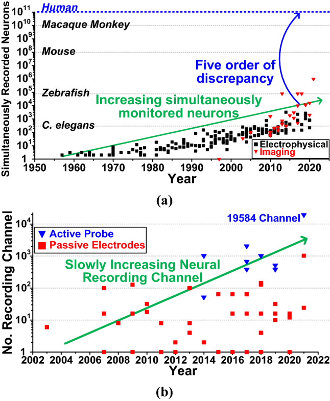
Yearly trend of a simultaneously recorded neurons and b a number of channels of the neural recording system implemented in integrated circuits
Figure 2b shows the yearly research trend of the implemented neural recording systems with active probes (blue triangles) or passive probes (red squares). It can be observed that the number of neural recording channel implemented in integrated circuits was slowly rising from single channel to thousands of channels [59–74, 75]. The state-of-the-art implantable neural recording system was proposed by Neuralink [66], but the number of neural recording channels is still limited to 1024. Even considering in-vitro silicon probe implementation [67], still 19,584 electrodes and recording channels were implemented, which is smaller than imaging methods. From this, the need for high-density neural recording system that can monitor thousands of channels in real-time in fully implantable device is still highly required.
This paper provides a general review of the high-density neural recording system and its requirements. To understand the specifications of the neural recording system, general knowledge about neural signals is given in Sect. 2. Then, the overall neural recording system structure and its figure-of-merit are explained in Sect. 3. In Sect. 4, conventional neural processing circuits with state-of-the-art processing algorithms are presented, and Sect. 5 concludes this article.
Neural signal
The action potential (AP) signal generated by the ion movement at a neuron cell is the basis of the neural signal. In the resting state, transmembrane proteins in the neuronal membrane keep the concentration of potassium (K+) and chloride (Cl−) ions inside the cell high relative to outside the cell, while the concentration of sodium (Na+) ions low [76]. In this state, diffusion force and electrical force of individual ions reach an equilibrium state, and the membrane potential can be calculated by Goldman–Hodgkin–Katz equation as −70 mV. When excitatory synaptic input is delivered to the neuron, the depolarization of neuron membrane leads to influx of Na+ and outflux of K+. This ion movement causes sharp transient potential differences and can be measured with electrodes such as patch-clamp or depth electrodes.
Measuring this transient voltage potential can be performed in two ways: Outside the cell membrane or inside the cell membrane. Measurement of the potential inside the cell with a sharp electrode, which penetrates the neuron cell membrane, is referred to as intracellular recording, and measurement of the potential outside the cell is referred to as extracellular recording. Intracellular AP recording typically has voltage amplitude of 10–70 mVpp and a frequency range of 100 Hz–10 kHz. However, penetrating cell membrane results in cell death in several hours, so most of in-vivo experiments are done in an extracellular way. Extracellular AP (also known as neural spike) recording provides a relatively safe recording environment, but its measured signal is significantly degraded compared to intracellular AP due to filtering properties through the extracellular medium and cell membrane. Its voltage amplitude falls about two to three orders of magnitude compared to the intracellular AP to be 50–500 uVpp, and its frequency response becomes slightly high-passed filtered.
A single-neuron level recording with a close-spaced electrode can measure neural spikes more accurately. However, if multiple neurons are present near the electrode, the low-frequency component of each neural spike is measured as a slow drift like a transient signal because cell fluid between neuron and cell membrane acts as a low-pass filter. This signal is called the local field potential (LFP) and also can be used in various applications. LFP has a typical value of 0.5–5 mVPP and a frequency band of 1 mHz–200 Hz. Figure 3 shows the waveforms of the typical neural signal and its filtered signal. It can be observed that the spike-vague raw neural signals can be divided into fast-moving neural spikes and slow-moving LFP with proper frequency filtering.
Fig. 3.

Recorded waveforms of a typical raw neural signals and b its filtered signals
Measuring neural spikes and sorting their timing are important in many applications. However, for large-population neural activities, measuring every single neuron is not possible because the number of neurons is too high. Therefore, another neural signal that can represent the large-population activity of nearby neurons can be further considered. This signal is called multi-unit activity (MUA) and proved useful in many studies [44, 77–79]. Figure 4 shows how MUA is calculated along with its transient waveform compared to the raw neural signal. Since the MUA signal is band-passed in neural spike frequency of 300–6000 Hz and calculated in root-mean-square, it is also called as spike band power (SBP). Compared to LFP, MUA provides more local activity of neurons. The LFP measured at any electrode typically has sizable contributions from neurons that are located several hundred micrometers away. In [80], when measuring the neuron population at a point 500 μm away, LFP decayed 5 times compared to the population center value, but MUA decayed 30 times which showed that distance-decay of the MUA is much greater than LFP. Thus, the local activity of the neuron network can be measured and estimated with MUA. Table 1 summarized neural signal modalities and their characteristics.
Fig. 4.

Raw neural signal and its calculated multi-unit activity (MUA) signal
Table 1.
Summary of neural signals and their characteristics
| Neural signal | Signal amplitude | Signal frequency | Spatial extent (mm) | Simultaneously recordable neurons |
|---|---|---|---|---|
| Action potential (patch clamp | 10–70 mVPP | 100 Hz–10 kHz | – | 1 individual neurons |
| Neural spike (depth electrode) | 50–500 μVPP | 100 Hz–10 kHz | − 0.1 | 10–100 individual neurons |
| Local field potential (depth electrode) | 0.5–5 mVPP | 1 mHz–200 Hz | − 3 | Medium population of neurons |
| Multi unit activity (depth electrode) | 10–400 μVPP | 300 Hz–6 kHz | − 0.2 | Small population of neurons |
| ECoG (Dura Surface Elec.) | 10–1 mVPP | 1 mHz–500 Hz | – | Large population of neurons |
| EEG (Scalp Surface Elec.) | 10–100 μVPP | 1–20 Hz | – | Very large population of neurons |
High-density neural recording system
Requirements for implantable system
As explained in Sect. 2, most of the neural signals (e.g., AP, LFP, MUA, ECoG, etc.) have very weak amplitude and audio level frequency range. Furthermore, since it is implanted inside the living body, the design of a neural recording integrated circuit requires unique specifications.
Power consumption of the implantable system is the most important consideration because it is directly related to heat generation of the device [81]. A recent study showed that implanted systems dissipating more than 40 mW of power can cause a temperature increase of more than 2 °C and lead to cell death in days [82]. The input-referred noise (IRN) is also an important parameter because neural signals suffer from very weak voltage amplitude. High IRN directly leads to a drastic drop of signal-to-noise ratio (SNR). To measure LFP or ECoG, a neural recording system should be able to handle a very low-frequency band for neural signal integrity. The variable gain control is another important consideration against PVT variations that can affect the system performance. Common-mode rejection ratio (CMRR) and power supply rejection ratio (PSRR) should be also considered because the common-mode signal is fed through electrodes and power supply noise from wall-mounted 50/60 Hz or switching noise from the wireless power supply can pose SNR degradation. In addition, electrode-tissue interface tends to have up to several MΩ ranges and a few hundred DC offsets, so input impedance and DC rejection of neural recording channels should be carefully checked for signal integrity. Finally, for high-density neural recording more than hundreds of channels, the silicon area of each recording channel should be minimized. Table 2 shows the design specifications and primary considerations in integrated neural recording systems.
Table 2.
Design specification and primary consideration in integrated neural recording systems
| Specification | Primary consideration | Typical range | References | |
|---|---|---|---|---|
Power consumption 
|
Heat | Pchip < 40 mW for Δt < 2 °C | 2.72–33 μW | [58, 71] |
| IRN | Input transconductance(gm, in) ∝ ID | |||
Input referred noise(IRN) 
|
Input signal amplitude | Low IRN to achieve high SNR for signals as small as 50 μVPP | 3.46–8.98 μVrms | [65, 71] |
3-dB bandwidth 
|
Input signal frequency range | Bandpass ability for frequency band of input neural signal | 0.5 Hz–10 kHz | [64, 71] |
Variable gain 
|
Input signal amplitude | Adjustable gain to achieve highest dynamic range | 52–68 dB | [71] |
CMRR, PSRR 
|
Power, common noise rejection | Reject common-mode signal at 50/60 Hz and reject power supply noise | 75–92 dB | [64, 71] |
Input impedance 
|
Electrode-tissue interface | Higher input impedance than electrode-tissue interface for signal integrity | 100 MΩ–10 TΩ | [6, 18] |
DC rejection 
|
Electrode-tissue interface | Block DC offset at electrode-tissue interface to prevent saturation | 0.1–1 Hz | [17, 18, 74] |
Area 
|
Multi-channel implementation | Consume little silicon area as possible for multi-channel implementation | 0.03–20 mm2 | [68, 71] |
 :To be maximized;
  : Depend on signal;
  : To be minimized
Neural recording channel
As explained in Sect. 3.1, there are many required specifications when designing a neural recording system. To satisfy those specifications, researchers have proposed advanced architectures and elements in the neural recording system. Figure 5 shows the conventional neural recording system which consists of a low-noise amplifier (LNA), analog-to-digital converter (ADC), and wireless telemetry circuit. Typically, multiple LNAs share the single ADC to save silicon area and power consumption as shown in Fig. 5. For that, an analog multiplexer can be used before ADC to time-multiplex the neural signals from several LNAs. A multiplexed neural signal which has a frequency band up to 10 M kHz is fed to ADC, where M is the number of LNAs connected to one ADC, so the sampling speed of ADC should be at least 20 M kHz to satisfy the Nyquist criterion. Then, for N-bit resolution ADC, the digitized neural signal will be 20 k M N/ s. The wireless telemetry circuit can be either an inductive link or an RF link depending on data rate to communicate outside the body through the skin [83–85].
Fig. 5.

Conventional neural recording systems that consist of electrodes, LNA, multiplexor, ADC, and wireless telemetry
When the electrode provides a weak neural signal, LNA amplifies the neural signal which is then digitized through ADC. As explained in Sect. 3.1, there are several considerations for designing LNA, and the LNA structure can be classified according to how the DC offset of the electrode-tissue interface is removed. The AC-coupled structure uses capacitors to remove DC offset, while the DC-coupled structure uses a low-pass filter in the feedback structure. A well-organized review about neural recording amplifiers can be found in [86].
Among various amplifier structures used in the LNA, the current-reuse structure has been widely used because of its high input transconductance [24]. Since the amplifier inside LNA usually dominates the overall IRN of the recording channel, minimizing the amplifier noise is crucial to increase SNR. As explained in [87], the input transconductance of an amplifier (gm, IN) is the dominant factor for decreasing the amplifier noise. Figure 6 shows the current-reuse amplifier structure proposed in [37]. Compared to conventional amplifiers with only NMOS or PMOS transistors as their input stage, the current-reuse amplifier employs both NMOS and PMOS in an inverter structure to share the same drain current.
Fig. 6.

Conventional differential input stage and current-reuse differential input stage in neural amplifiers
Considering only thermal noise of transistors, the current noise power spectral density is modeled as:
| 1 |
where k is the Boltzmann constant, T is the absolute temperature in kelvin, γ is the thermal noise coefficient, and gm is the transconductance of the input transistor.
For the conventional amplifier with NMOS only input stage, input-referred noise can be calculated as follows:
| 2 |
For the current-reuse amplifier, input-referred noise is calculated as follows:
| 3 |
It can be observed that the effective input transconductance (gm, IN) is the sum of transconductance of NMOS (gm, N) and PMOS (gm, P). When the same current noise density and transconductance for NMOS and PMOS are assumed, input-referred noise of the current-reuse amplifier is:
| 4 |
which is half of the INR from the conventional amplifier [37]. A small increase of PMOS transistor area can lead to a drastic reduction of IRN, while consuming the same static current.
In addition, there are several types of ADCs that can be employed in neural recording systems. Figure 7 shows the general trade-off relationship between sampling rate and resolution and the candidates for neural ADC [88]. In case the neural recording ADC samples neural spikes which have a frequency range up to 10 kHz, the minimum sampling speed should be 20 kHz. For power and area efficient ADC, a successive approximation register (SAR) ADC is the most general choice among them.
Fig. 7.

ADC structures for neural recording systems depending on resolution and sampling rate
Figure of merit for neural recording
To compare the performance between various neural recording channels, a figure-of-merit (FoM) has been widely adopted. There are two types of FoM: (1) noise efficiency factor (NEF) and power efficiency factor (PEF), and (2) channel-FoM (Ch. FoM) and energy-area FoM (E-A FoM).
NEF represents the relationship of the noise-current trade-off in the amplifier and has the lower limit of 1, which means the thermal noise of a single BJT amplifier. While NEF only considers the current from the supply, PEF considers the supply voltage as well. NEF and PEF are defined as following [27, 89]:
| 5 |
| 6 |
where VIRN is the total input-referred noise of amplifier, Itot the total current from the supply, Vt the thermal voltage, which is about 26 mV, BW the −3 dB bandwidth of the system, and VDD is the supply voltage of the amplifier. Therefore, NEF is generally used for neural recording channel and PEF is often used to emphasize the power consumption of neural recording channel. Even though NEF and PEF provide good insight into the trade-off between power consumption and noise, they are not the complete FoM for neural recording channels because they only cover the power and noise trade-off. The other important aspects, such as silicon area, dynamic range, input impedance, etc., are not considered in NEF, PEF. Recent yearly NEF trends can be found in [6].
To include the silicon area as comparison factor, which is an important parameter for high-density neural recording systems, channel FoM (Ch. FoM) and energy-area FoM (E-A FoM) are proposed in [69] and defined as follows:
| 7 |
| 8 |
where PCh is the averaged power consumption of a single recording channel, ENOBCh is the measured maximum effective number of bits, fs is the sampling frequency, and ACh is averaged area per channel which includes the amplifier, buffer, and ADC. Recent yearly research trends for Ch. FoM and E–A FoM, which consider the area, power, and noise trade-off, can be found in [5].
Neural signal processing system
Neural spike detection algorithm
As explained in Sect. 3.2, the wireless telemetry circuit transmits digitized neural signals outside the body through the wireless link [71]. However, in high-density neural recording, the high data rate become a bottleneck. For example, a 256-channel neural recording system with 10-bit ADC resolution requires high data rate of 51.2 Mbps. Furthermore, the power consumption of the wireless telemetry circuit depends on the data rate as well. Assuming the data rate of 200 kbps per channel and energy consumption of 50 pJ/bit, the wireless telemetry requires 10 μW/channel, which exceeds the power consumption of the neural recording channel itself [43]. To address this issue, an on-chip neural signal processing such as a spike detection algorithm can be used to reduce the data rate.
There are mainly two types of spike detection algorithms that can easily be implemented in neural system IC [90]; (1) threshold-crossing detection and (2) nonlinear energy operator (NEO), as shown in Fig. 8. The threshold-crossing detection was proposed in the late 1990s [91] with using simple analog comparators. When the neural signal crosses a pre-defined value (threshold), the output of the comparator shows the binary value of one. Then, the neural spike can be captured with using the comparator outputs. This method is very simple and easy to implement, but the main downfall is how to determine the threshold value (VTH), which may varies depending on environments. Conventionally, VTH is determined as follows [92]:
| 9 |
| 10 |
where xbp is bandpass-filtered signal and σn is a standard deviation of the background noise. If VTH is universally applied to all recording channels, variations such as distance to nearby neurons, type of neurons, and PVT variation of the chip can cause false detection of spikes or missing neural spikes.
Fig. 8.

Spike detection algorithm: a threshold crossing and b nonlinear energy operator (NEO)
To overcome such disadvantages of the threshold-crossing detection method, researchers have used a nonlinear energy operator (NEO) that takes into consideration of the energy-level difference between transient points rather than the absolute transient value itself [93–96]. For the continuous-time function x(n), NEO(n) is defined as follows:
| 11 |
Equation 9 implies that NEO(n) can be maximized when both amplitude and frequency of x(n) are large. After detection, the wireless telemetry can send only selected data such as neural spike signals, which significantly reduces the required data rate.
High-density neural recording system with signal processing
The limitation of the conventional neural spike detection algorithm is that it tries to find neural spikes after measuring raw neural signals from all electrodes, which already wastes power and area for recording channels. Since the number of neurons in the brain is very large, the number of neurons firing simultaneously is limited. In [97], based on the energy consumption of the brain and single neural spike, the author concluded that under 1% of neurons are active simultaneously. If the signals from non-active brain regions are recorded and processed through the system, then power and area consumption are wasted. Thus, the advanced electrode-selection algorithm is proposed based on the relative neuron activation which is evaluated based on MUA [63].
As explained in Sect. 2, MUA represents the local neural population’s activation. Therefore, relative local activity can be compared by observing MUA, and the most activated areas of the brain can be selected. Then, the neural spikes from those selected area (electrodes) can be recorded with a fewer number of recording channels. For example, the activated electrodes among 32 electrodes can be automatically connected and recorded with 12 recording channels by using 8-channel neural spike scanning circuits as shown in Fig. 9. The neural scanning channel consists of a power-efficient amplifier and a squaring circuit to calculate MUA. Then, the controller compares the MUA values from each scanning channel, and three most activated electrodes groups are selected and connected to 12 neural recording channels. With using the neural scanning method, the neural recording system can save the power and silicon area while still measuring the neural spikes from activated electrodes.
Fig. 9.

Adaptive electrode-selection method with neural scanning for high-density neural recording systems
Conclusion
In this paper, requirements and implementation of the high-density neural recording system are covered. The difference between non-invasive and invasive neural signals is explained, while several types of neural signals including MUA are described. The paper also discussed about the figure-of-merits and issues of the conventional recording system. In the end, the neural recording systems with signal processing functions are introduced which can provide a promising solution for high-density neural recording while using the limited hardware resources.
Acknowledgements
Chip fabrication and EDA tools were supported by IC Design Education Center (IDEC), Korea.
Funding
This work was supported by national research foundation of Korea (NRF-2020R1F1A1074719 and 2020M3F3A2A01081240) funded by ministry of science & ICT.
Declarations
Conflict of interest
Han-Sol Lee declares that he has no conflict of interest. Kyeongho Eom declares that he has no conflict of interest. Minju Park declares that she has no conflict of interest. Seung-Beom Ku declares that he has no conflict of interest. Kwonhong Lee declares that he has no conflict of interest. Hyung-Min declares that he has no conflict of interest.
Ethical approval
This article does not contain any studies with human participants or animals performed by any of the authors.
Footnotes
Publisher's Note
Springer Nature remains neutral with regard to jurisdictional claims in published maps and institutional affiliations.
References
- 1.Sprengers M, Vonck K, Carrette E, Marson AG, Boon P. Deep brain and cortical stimulation for epilepsy. Cochrane Database Syst Rev. 2017. [DOI] [PMC free article] [PubMed]
- 2.Benabid AL. Deep brain stimulation for Parkinson’s disease. Curr Opin Neurobiol. 2003;13:696–706. doi: 10.1016/j.conb.2003.11.001. [DOI] [PubMed] [Google Scholar]
- 3.Ostrem JL, Starr PA. Treatment of dystonia with deep brain stimulation. Neurotherapeutics. 2008;5:320–330. doi: 10.1016/j.nurt.2008.01.002. [DOI] [PMC free article] [PubMed] [Google Scholar]
- 4.Keller D, Erö C, Markram H. Cell densities in the mouse brain: a systematic review. Front Neuroanat. 2018;12:83. doi: 10.3389/fnana.2018.00083. [DOI] [PMC free article] [PubMed] [Google Scholar]
- 5.Luan L, Robinson JT, Aazhang B, et al. Recent advances in electrical neural interface engineering: minimal invasiveness, longevity, and scalability. Neuron. 2020;108:302–321. doi: 10.1016/j.neuron.2020.10.011. [DOI] [PMC free article] [PubMed] [Google Scholar]
- 6.Ha S, Kim C, Mercier PP, Cauwenberghs G. High-density integrated electrocortical neural interfaces: low-noise low-power system-on-chip design methodology. Elsevier; 2019. [Google Scholar]
- 7.Logothetis NK. The neural basis of the blood-oxygen-level-dependent functional magnetic resonance imaging signal. Philos Trans R Soc B Biol Sci. 2002;357:1003. doi: 10.1098/rstb.2002.1114. [DOI] [PMC free article] [PubMed] [Google Scholar]
- 8.Higgins G, Salim S, Zhang C, et al. Biomechanical analysis of silicon microelectrode-induced strain in the brain. J Neural Eng. 2005;2:81. doi: 10.1088/1741-2560/2/4/003. [DOI] [PubMed] [Google Scholar]
- 9.McConnell GC, Rees HD, Levey AI, et al. Implanted neural electrodes cause chronic, local inflammation that is correlated with local neurodegeneration. J Neural Eng. 2009;6:056003. doi: 10.1088/1741-2560/6/5/056003. [DOI] [PubMed] [Google Scholar]
- 10.Karumbaiah L, Saxena T, Carlson D, et al. Relationship between intracortical electrode design and chronic recording function. Biomaterials. 2013;34:8061–8074. doi: 10.1016/j.biomaterials.2013.07.016. [DOI] [PubMed] [Google Scholar]
- 11.Harrison RR, Charles C. A low-power low-noise CMOS amplifier for neural recording applications. IEEE J Solid-State Circuits. 2003;38:958–965. doi: 10.1109/JSSC.2003.811979. [DOI] [Google Scholar]
- 12.Harrison RR, Watkins PT, Kier RJ, et al. A low-power integrated circuit for a wireless 100-electrode neural recording system. IEEE J Solid-State Circuits. 2007;42:123–133. doi: 10.1109/JSSC.2006.886567. [DOI] [Google Scholar]
- 13.Lee SB, Lee HM, Kiani M, et al. An inductively powered scalable 32-channel wireless neural recording system-on-a-chip for neuroscience applications. IEEE Trans Biomed Circuits Syst. 2010;4:360–371. doi: 10.1109/TBCAS.2010.2078814. [DOI] [PMC free article] [PubMed] [Google Scholar]
- 14.Fan Q, Sebastiano F, Huijsing JH, Makinwa KAA. A 1.8 μ W 60 nV/ √ Hz capacitively-coupled chopper instrumentation amplifier in 65 nm CMOS for wireless sensor nodes. IEEE J Solid-State Circuits. 2011;46:1534–1543. doi: 10.1109/JSSC.2011.2143610. [DOI] [Google Scholar]
- 15.Xu J, Yazicioglu RF, Grundlehner B, et al. A 160 μw 8-channel active electrode system for EEG monitoring. IEEE Trans Biomed Circuits Syst. 2011;5:555–567. doi: 10.1109/TBCAS.2011.2170985. [DOI] [PubMed] [Google Scholar]
- 16.Tseng Y, Ho Y, Kao S, Su C. A 0.09 μ W low power front-end biopotential amplifier for biosignal recording. IEEE Trans Biomed Circuits Syst. 2012;6:508–516. doi: 10.1109/TBCAS.2012.2188029. [DOI] [PubMed] [Google Scholar]
- 17.Zhang F, Holleman J, Otis BP. Design of ultra-low power biopotential amplifiers for biosignal acquisition applications. IEEE Trans Biomed Circuits Syst. 2012;6:344–355. doi: 10.1109/TBCAS.2011.2177089. [DOI] [PubMed] [Google Scholar]
- 18.Harrison RR. A versatile integrated circuit for the acquisition of biopotentials. In: Proc IEEE 2007 Cust Integr Circuits Conf CICC 2007. pp. 115–22.
- 19.Yazicioglu RF, Merken P, Puers R, Van Hoof C. A 60 μW 60 nV/√Hz readout front-end for portable biopotential acquisition systems. IEEE J Solid-State Circuits. 2007;42:1100–1110. doi: 10.1109/JSSC.2007.894804. [DOI] [Google Scholar]
- 20.Denison T, Consoer K, Santa W, et al. A2 μw 100 nV/rtHz chopper-stabilized instrumentation amplifier for chronic measurement of neural field potentials. IEEE J Solid-State Circuits. 2007;42:2934–2945. doi: 10.1109/JSSC.2007.908664. [DOI] [Google Scholar]
- 21.Yazicioglu RF, Merken P, Puers R, Van Hoof C. A 200 μ weight-channel EEG acquisition ASIC for ambulatory EEG systems. IEEE J Solid-State Circuits. 2008;43:3025–3038. doi: 10.1109/JSSC.2008.2006462. [DOI] [Google Scholar]
- 22.Zou X, Xu X, Yao L, Lian Y. A 1-V 450-nW fully integrated programmable biomedical sensor interface chip. IEEE J Solid-State Circuits. 2009;44:1067–1077. doi: 10.1109/JSSC.2009.2014707. [DOI] [Google Scholar]
- 23.Mollazadeh M, Murari K, Cauwenberghs G, Thakor N. Micropower CMOS integrated low-noise amplification, filtering, and digitization of multimodal neuropotentials. IEEE Trans Biomed Circuits Syst. 2009;3:1–10. doi: 10.1109/TBCAS.2008.2005297. [DOI] [PMC free article] [PubMed] [Google Scholar]
- 24.Chae MS, Yang Z, Yuce MR, et al. A 128-channel 6 mW wireless neural recording IC with spike feature extraction and UWB transmitter. IEEE Trans Neural Syst Rehabil Eng. 2009;17:312–321. doi: 10.1109/TNSRE.2009.2021607. [DOI] [PubMed] [Google Scholar]
- 25.Verma N, Shoeb A, Bohorquez J, et al. A micro-power EEG acquisition SoC with integrated feature extraction processor for a chronic seizure detection system. IEEE J Solid-State Circuits. 2010;45:804–816. doi: 10.1109/JSSC.2010.2042245. [DOI] [Google Scholar]
- 26.Polikov VS, Tresco PA, Reichert WM. Response of brain tissue to chronically implanted neural electrodes. J Neurosci Methods. 2005;148:1–18. doi: 10.1016/j.jneumeth.2005.08.015. [DOI] [PubMed] [Google Scholar]
- 27.Muller R, Gambini S, Rabaey JM. A 0.013 mm2, 5 μ W, DC-coupled neural signal acquisition ic with 0.5 v supply. IEEE J Solid-State Circuits. 2012;47:232–243. doi: 10.1109/JSSC.2011.2163552. [DOI] [Google Scholar]
- 28.Han D, Zheng Y, Rajkumar R, et al. A 0.45 v 100-channel neural-recording IC with sub-μW/Channel consumption in 0.18 μ CMOS. IEEE Trans Biomed Circuits Syst. 2013;7:735–746. doi: 10.1109/TBCAS.2014.2298860. [DOI] [PubMed] [Google Scholar]
- 29.Yang T, Holleman J. An ultralow-power low-noise CMOS biopotential amplifier for neural recording. IEEE Trans Circuits Syst II Express Briefs. 2015;62:927–931. doi: 10.1109/TCSII.2015.2457811. [DOI] [Google Scholar]
- 30.Song S, Rooijakkers M, Harpe P, et al. A low-voltage chopper-stabilized amplifier for fetal ECG monitoring with a 1.41 power efficiency factor. IEEE Trans Biomed Circuits Syst. 2015;9:237–247. doi: 10.1109/TBCAS.2015.2417124. [DOI] [PubMed] [Google Scholar]
- 31.Harpe P, Gao H, Van Dommele R, et al. A 0.20 mm2 3 nW signal acquisition IC for miniature sensor nodes in 65 nm CMOS. IEEE J Solid-State Circuits. 2016;51:240–248. doi: 10.1109/JSSC.2015.2487270. [DOI] [Google Scholar]
- 32.Ando H, Takizawa K, Yoshida T, et al. wireless multichannel neural recording with a 128-Mbps UWB transmitter for an implantable brain-machine interfaces. IEEE Trans Biomed Circuits Syst. 2016;10:1068–1078. doi: 10.1109/TBCAS.2016.2514522. [DOI] [PubMed] [Google Scholar]
- 33.Liu X, Zhang M, Xiong T, et al. A fully integrated wireless compressed sensing neural signal acquisition system for chronic recording and brain machine interface. IEEE Trans Biomed Circuits Syst. 2016;10:874–883. doi: 10.1109/TBCAS.2016.2574362. [DOI] [PubMed] [Google Scholar]
- 34.Lee B, Ghovanloo M. An adaptive averaging low noise front-end for central and peripheral nerve recording. IEEE Trans Circuits Syst II Express Briefs. 2018;65:839–843. doi: 10.1109/TCSII.2017.2725988. [DOI] [PMC free article] [PubMed] [Google Scholar]
- 35.Johnson B, Molnar A. An orthogonal current-reuse amplifier for multi-channel sensing. IEEE J Solid-State Circuits. 2013;48:1487–1496. doi: 10.1109/JSSC.2013.2257478. [DOI] [Google Scholar]
- 36.Yoo J, Yan L, El-Damak D, et al. An 8-channel scalable EEG acquisition SoC with patient-specific seizure classification and recording processor. IEEE J Solid-State Circuits. 2013;48:214–228. doi: 10.1109/JSSC.2012.2221220. [DOI] [Google Scholar]
- 37.Zou X, Liu L, Cheong JH, et al. A 100-Channel 1-mW implantable neural recording IC. IEEE Trans Circuits Syst I Regul Pap. 2013;60:2584–2596. doi: 10.1109/TCSI.2013.2249175. [DOI] [Google Scholar]
- 38.Chen Y, Basu A, Liu L, et al. A digitally assisted, signal folding neural recording amplifier. IEEE Trans Biomed Circuits Syst. 2014;8:528–542. doi: 10.1109/TBCAS.2013.2288680. [DOI] [PubMed] [Google Scholar]
- 39.Wang TY, Lai MR, Twigg CM, Peng SY. A fully reconfigurable low-noise biopotential sensing amplifier with 1.96 noise efficiency factor. IEEE Trans Biomed Circuits Syst. 2014;8:411–422. doi: 10.1109/TBCAS.2013.2278659. [DOI] [PubMed] [Google Scholar]
- 40.Ballini M, Muller J, Livi P, et al. A 1024-channel CMOS microelectrode array with 26,400 electrodes for recording and stimulation of electrogenic cells in vitro. IEEE J Solid-State Circuits. 2014;49:2705–2719. doi: 10.1109/JSSC.2014.2359219. [DOI] [PMC free article] [PubMed] [Google Scholar]
- 41.Lopez CM, Andrei A, Mitra S, et al. An implantable 455-active-electrode 52-channel CMOS neural probe. IEEE J Solid-State Circuits. 2014;49:248–261. doi: 10.1109/JSSC.2013.2284347. [DOI] [Google Scholar]
- 42.Muller R, Le HP, Li W, et al. A minimally invasive 64-channel wireless μeCoG implant. IEEE J Solid-State Circuits. 2015;50:344–359. doi: 10.1109/JSSC.2014.2364824. [DOI] [Google Scholar]
- 43.Chen Y, Yao E, Basu A. A 128-channel extreme learning machine-based neural decoder for brain machine interfaces. IEEE Trans Biomed Circuits Syst. 2016;10:679–692. doi: 10.1109/TBCAS.2015.2483618. [DOI] [PubMed] [Google Scholar]
- 44.Irwin ZT, Thompson DE, Schroeder KE, et al. Enabling low-power, multi-modal neural interfaces through a common, low-bandwidth feature space. IEEE Trans Neural Syst Rehabil Eng. 2016;24:521–531. doi: 10.1109/TNSRE.2015.2501752. [DOI] [PubMed] [Google Scholar]
- 45.Johnson BC, Gambini S, Izyumin I, et al. An implantable 700μW 64-channel neuromodulation IC for simultaneous recording and stimulation with rapid artifact recovery. In: IEEE Symp VLSI circuits, Dig Tech Pap 2017. pp. C48–C49.
- 46.Zhang J, Zhang H, Sun Q, Zhang R. A low-noise, low-power amplifier with current-reused ota for ecg recordings. IEEE Trans Biomed Circuits Syst. 2018;12:700–708. doi: 10.1109/TBCAS.2018.2819207. [DOI] [PubMed] [Google Scholar]
- 47.Shen L, Lu N, Sun N. A 1-V 0.25- μw inverter stacking amplifier with 1.07 noise efficiency factor. IEEE J Solid-State Circuits. 2018;53:896–905. doi: 10.1109/JSSC.2017.2786724. [DOI] [Google Scholar]
- 48.Kim C, Joshi S, Courellis H, et al. Sub-μ Vrms-noise Sub-μ W/Channel ADC-direct neural recording with 200-mV/ms transient recovery through predictive digital autoranging. IEEE J Solid-State Circuits. 2018;53:3101–3110. doi: 10.1109/JSSC.2018.2870555. [DOI] [Google Scholar]
- 49.Rezaei M, Maghsoudloo E, Bories C, et al. A low-power current-reuse analog front-end for high-density neural recording implants. IEEE Trans Biomed Circuits Syst. 2018;12:271–280. doi: 10.1109/TBCAS.2018.2805278. [DOI] [PubMed] [Google Scholar]
- 50.Yaul FM, Chandrakasan AP. A noise-efficient 36 nV/√hz chopper amplifier using an inverter-based 0.2-V supply input stage. IEEE J Solid-State Circuits. 2017;52:3032–3042. doi: 10.1109/JSSC.2017.2746778. [DOI] [Google Scholar]
- 51.Kassiri H, Salam MT, Pazhouhandeh MR, et al. Rail-to-rail-input dual-radio 64-channel closed-loop neurostimulator. IEEE J Solid-State Circuits. 2017;52:2793–2810. [Google Scholar]
- 52.Delgado-Restituto M, Rodriguez-Perez A, Darie A, et al. System-level design of a 64-channel low power neural spike recording sensor. IEEE Trans Biomed Circuits Syst. 2017;11:420–433. doi: 10.1109/TBCAS.2016.2618319. [DOI] [PubMed] [Google Scholar]
- 53.Liu X, Zhang M, Richardson AG, et al. Design of a closed-loop, bidirectional brain machine interface system with energy efficient neural feature extraction and PID control. IEEE Trans Biomed Circuits Syst. 2017;11:729–742. doi: 10.1109/TBCAS.2016.2622738. [DOI] [PubMed] [Google Scholar]
- 54.Raducanu BC, Yazicioglu RF, Lopez CM, et al. Time multiplexed active neural probe with 1356 parallel recording sites. Sensors. 2017;17:2388. doi: 10.3390/s17102388. [DOI] [PMC free article] [PubMed] [Google Scholar]
- 55.Mora Lopez C, Putzeys J, Raducanu BC, et al. A neural probe with up to 966 electrodes and up to 384 configurable channels in 0.13 μm SOI CMOS. IEEE Trans Biomed Circuits Syst. 2017;11:510–522. doi: 10.1109/TBCAS.2016.2646901. [DOI] [PubMed] [Google Scholar]
- 56.Liu Y, Luan S, Williams I, et al. A 64-channel versatile neural recording SoC with activity-dependent data throughput. IEEE Trans Biomed Circuits Syst. 2017;11:1344–1355. doi: 10.1109/TBCAS.2017.2759339. [DOI] [PubMed] [Google Scholar]
- 57.Dragas J, Viswam V, Shadmani A, et al. In vitro multi-functional microelectrode array featuring 59 760 electrodes, 2048 electrophysiology channels, stimulation, impedance measurement, and neurotransmitter detection channels. IEEE J Solid-State Circuits. 2017;52:1576–1590. doi: 10.1109/JSSC.2017.2686580. [DOI] [PMC free article] [PubMed] [Google Scholar]
- 58.Urai AE, Doiron B, Leifer AM, Churchland AK. Large-scale neural recordings call for new insights to link brain and behavior. Nat Neurosci. 2022;25(1):11–19. doi: 10.1038/s41593-021-00980-9. [DOI] [PubMed] [Google Scholar]
- 59.Demas J, Manley J, Tejera F, et al. High-speed, cortex-wide volumetric recording of neuroactivity at cellular resolution using light beads microscopy. Nat Methods. 2021;18(9):1103–1111. doi: 10.1038/s41592-021-01239-8. [DOI] [PMC free article] [PubMed] [Google Scholar]
- 60.Lopez CM, Chun HS, Wang S, et al. A multimodal CMOS MEA for high-throughput intracellular action potential measurements and impedance spectroscopy in drug-screening applications. IEEE J Solid-State Circuits. 2018;53:3076–3086. doi: 10.1109/JSSC.2018.2863952. [DOI] [Google Scholar]
- 61.De Dorigo D, Moranz C, Graf H, et al. Fully immersible subcortical neural probes with modular architecture and a delta-sigma ADC integrated under each electrode for parallel readout of 144 recording sites. IEEE J Solid-State Circuits. 2018;53:3111–3125. doi: 10.1109/JSSC.2018.2873180. [DOI] [Google Scholar]
- 62.Jia Y, Guler U, Lai YP, et al. A Trimodal Wireless Implantable Neural Interface System-on-Chip. IEEE Trans Biomed Circuits Syst. 2020;14:1207–1217. doi: 10.1109/TBCAS.2020.3037452. [DOI] [PMC free article] [PubMed] [Google Scholar]
- 63.Lee HS, Park H, Lee HM. A multi-channel neural recording system with adaptive electrode selection for high-density neural interface. In: Proc Annu Int Conf IEEE Eng Med Biol Soc EMBS. 2020. pp. 4306–9. [DOI] [PubMed]
- 64.Lim J, Moon E, Barrow M, et al. A 0.19×0.17mm2 Wireless Neural Recording IC for Motor Prediction with Near-Infrared-Based Power and Data Telemetry. In: Dig Tech Pap–IEEE Int Solid-State Circuits Conf. 2020. pp. 416–8. [DOI] [PMC free article] [PubMed]
- 65.Wendler D, De DD, Amayreh M, et al. 28.7 A 0.00378mm2Scalable neural recording front-end for fully immersible neural probes based on a two-step incremental delta-sigma converter with extended counting and hardware reuse. Dig Tech Pap - IEEE Int Solid-State Circuits Conf. 2021;64:398–400. [Google Scholar]
- 66.Yoon DY, Pinto S, Chung SW, et al. A 1024-Channel simultaneous recording neural SoC with stimulation and real-time spike detection. In: IEEE Symp VLSI Circuits, Dig Tech Pap 2021 June.
- 67.Yuan X, Hierlemann A, Frey U. Extracellular recording of entire neural networks using a dual-mode microelectrode array with 19 584 electrodes and high SNR. IEEE J Solid-State Circuits. 2021;56:2466–2475. doi: 10.1109/JSSC.2021.3066043. [DOI] [PMC free article] [PubMed] [Google Scholar]
- 68.Zhou A, Santacruz SR, Johnson BC, et al. A wireless and artefact-free 128-channel neuromodulation device for closed-loop stimulation and recording in non-human primates. Nat Biomed Eng. 2018;31(3):15–26. doi: 10.1038/s41551-018-0323-x. [DOI] [PubMed] [Google Scholar]
- 69.Park SY, Cho J, Na K, Yoon E. Modular 128-channel Δ - ΔΣ analog front-end architecture using spectrum equalization scheme for 1024-channel 3-D neural recording microsystems. IEEE J Solid-State Circuits. 2018;53:501–514. doi: 10.1109/JSSC.2017.2764053. [DOI] [Google Scholar]
- 70.Ng KA, Yuan C, Rusly A, et al. A wireless multi-channel peripheral nerve signal acquisition system-on-chip. IEEE J Solid-State Circuits. 2019;54:2266–2280. doi: 10.1109/JSSC.2019.2909158. [DOI] [Google Scholar]
- 71.Kim C, Park J, Ha S, et al. A 3 mm × 3 mm fully integrated wireless power receiver and neural interface system-on-chip. IEEE Trans Biomed Circuits Syst. 2019;13:1736–1746. doi: 10.1109/TBCAS.2019.2943506. [DOI] [PubMed] [Google Scholar]
- 72.KimSJ HSH, Cha JH, et al. A sub-μW/Ch analog front-end for delta -neural recording with spike-driven data compression. IEEE Trans Biomed Circuits Syst. 2019;13:1–14. doi: 10.1109/TBCAS.2018.2880257. [DOI] [PubMed] [Google Scholar]
- 73.Lee B, Jia Y, Abdollah Mirbozorgi S, et al. An inductively-powered wireless neural recording and stimulation system for freely-behaving animals. IEEE Trans Biomed Circuits Syst. 2019;13:413–424. doi: 10.1109/TBCAS.2019.2891303. [DOI] [PMC free article] [PubMed] [Google Scholar]
- 74.Angotzi GN, Boi F, Lecomte A, et al. SiNAPS: an implantable active pixel sensor CMOS-probe for simultaneous large-scale neural recordings. Biosens Bioelectron. 2019;126:355–364. doi: 10.1016/j.bios.2018.10.032. [DOI] [PubMed] [Google Scholar]
- 75.Wang S, Garakoui SK, Chun H, et al. A compact quad-shank CMOS neural probe with 5,120 addressable recording sites and 384 fully differential parallel channels. IEEE Trans Biomed Circuits Syst. 2019;13:1625–1634. doi: 10.1109/TBCAS.2019.2942450. [DOI] [PubMed] [Google Scholar]
- 76.Kandel ER, Schwartz JH, Jessell TM, et al. Principles of neural science. New York: McGraw-hill; 2000. [Google Scholar]
- 77.Irwin ZT, Schroeder KE, Vu PP, et al. Neural control of finger movement via intracortical brain–machine interface. J Neural Eng. 2017;14:066004. doi: 10.1088/1741-2552/aa80bd. [DOI] [PMC free article] [PubMed] [Google Scholar]
- 78.Nason SR, Vaskov AK, Willsey MS, et al. A low-power band of neuronal spiking activity dominated by local single units improves the performance of brain–machine interfaces. Nat Biomed Eng. 2020;410(4):973–983. doi: 10.1038/s41551-020-0591-0. [DOI] [PMC free article] [PubMed] [Google Scholar]
- 79.Stark E, Abeles M. Predicting Movement from Multiunit Activity. J Neurosci. 2007;27:8387–8394. doi: 10.1523/JNEUROSCI.1321-07.2007. [DOI] [PMC free article] [PubMed] [Google Scholar]
- 80.Pettersen KH, Hagen E, Einevoll GT. Estimation of population firing rates and current source densities from laminar electrode recordings. J Comput Neurosci. 2007;24(3):291–313. doi: 10.1007/s10827-007-0056-4. [DOI] [PubMed] [Google Scholar]
- 81.Kim S, Tathireddy P, Normann RA, Solzbacher F. Thermal impact of an active 3-D microelectrode array implanted in the brain. IEEE Trans Neural Syst Rehabil Eng. 2007;15:493–501. doi: 10.1109/TNSRE.2007.908429. [DOI] [PubMed] [Google Scholar]
- 82.Marblestone AH, Zamft BM, Maguire YG, et al. Physical principles for scalable neural recording. Front Comput Neurosci. 2013;7:137. doi: 10.3389/fncom.2013.00137. [DOI] [PMC free article] [PubMed] [Google Scholar]
- 83.Lee HS, Ahn J, Eom K, et al. A Power-Efficient Resonant Current Mode Receiver with Wide Input Range over Breakdown Voltages Using Automated Maximum Efficiency Control. IEEE Trans Power Electron. 2022;37:8738–8750. doi: 10.1109/TPEL.2022.3151427. [DOI] [Google Scholar]
- 84.Lee B, Ghovanloo M. An Overview of Data Telemetry in Inductively Powered Implantable Biomedical Devices. IEEE Commun Mag. 2019;57:74–80. doi: 10.1109/MCOM.2018.1800052. [DOI] [Google Scholar]
- 85.Lee B, Lee H-M. Wireless Applications. Handb Biochips 2022. pp. 949–66.
- 86.Noshahr FH, Nabavi M, Sawan M. Multi-Channel Neural Recording Implants: A Review. Sensors. 2020;20:904. doi: 10.3390/s20030904. [DOI] [PMC free article] [PubMed] [Google Scholar]
- 87.Gosselin B. Recent Advances in Neural Recording Microsystems. Sensors. 2011;11:4572–4597. doi: 10.3390/s110504572. [DOI] [PMC free article] [PubMed] [Google Scholar]
- 88.Kester W. Which ADC architecture is right for your application. In: EDA Tech Forum 2005. pp. 2–5.
- 89.Steyaert MSJ, Sansen WMC, Zhongyuan C. A Micropower Low-Noise Monolithic Instrumentation Amplifier For Medical Purposes. IEEE J Solid-State Circuits. 1987;22:1163–1168. doi: 10.1109/JSSC.1987.1052869. [DOI] [Google Scholar]
- 90.Gibson S, Judy JW, Marković D. Spike sorting: The first step in decoding the brain: The first step in decoding the brain. IEEE Signal Process Mag. 2012;29:124–143. doi: 10.1109/MSP.2011.941880. [DOI] [Google Scholar]
- 91.Lewicki MS. A review of methods for spike sorting: the detection and classification of neural action potentials. Netw Comput Neural Syst. 1998;9:R53. doi: 10.1088/0954-898X_9_4_001. [DOI] [PubMed] [Google Scholar]
- 92.Quiroga RQ, Nadasdy Z, Ben-Shaul Y. Unsupervised Spike Detection and Sorting with Wavelets and Superparamagnetic Clustering. Neural Comput. 2004;16:1661–1687. doi: 10.1162/089976604774201631. [DOI] [PubMed] [Google Scholar]
- 93.Kaiser JF. On a simple algorithm to calculate the “energy” of a signal. ICASSP, IEEE Int Conf Acoust Speech Signal Process - Proc. 1990;1:381–384. [Google Scholar]
- 94.Mukhopadhyay S, Ray GC. A new interpretation of nonlinear energy operator and its efficacy in spike detection. IEEE Trans Biomed Eng. 1998;45:180–187. doi: 10.1109/10.661266. [DOI] [PubMed] [Google Scholar]
- 95.Kim KH, Kim SJ. Neural spike sorting under nearly 0-dB signal-to-noise ratio using nonlinear energy operator and artificial neural-network classifier. IEEE Trans Biomed Eng. 2000;47:1406–1411. doi: 10.1109/10.871415. [DOI] [PubMed] [Google Scholar]
- 96.Obeid I, Wolf PD. Evaluation of spike-detection algorithms for a brain-machine interface application. IEEE Trans Biomed Eng. 2004;51:905–911. doi: 10.1109/TBME.2004.826683. [DOI] [PubMed] [Google Scholar]
- 97.Lennie P. The cost of cortical computation. Curr Biol. 2003;13:493–497. doi: 10.1016/S0960-9822(03)00135-0. [DOI] [PubMed] [Google Scholar]