Abstract
Zinc (Zn) and Zn alloys have been studied as potential materials for bioresorbable stents (BRSs) in the last decade due to their favorable biodegradability and biocompatibility. However, most Zn alloys lack the necessary combination of strength, ductility, fatigue resistance, corrosion rate (CR), and thermal stability needed for such applications. In this study, nanoparticles made of tungsten carbide (WC) were successfully incorporated into Zn alloyed with 0.5 wt % magnesium (Mg) and evaluated for their suitability for BRS applications. Specifically, the resulting Zn–0.5Mg–WC nanocomposite’s microstructure, mechanical properties, in vitro CR, and thermal stability were evaluated. The Zn–0.5Mg–WC nanocomposite had excellent mechanical strength [ultimate tensile strength (UTS) > 250 MPa], elongation to failure (>30%), and a suitable in vitro CR (~0.02 mm/y) for this clinical application. Moreover, the Zn–0.5Mg–WC nanocomposite survived 10 million cycles of tensile loading (stress ratio, R = 0.053) when the maximum stress was 80% of the yield stress. Its ductility was also retained during a 90-day thermal stability study, indicating an excellent shelf life. Stent prototypes were fabricated using this composition and were successfully deployed during bench testing without fracture. These results show that the Zn–0.5Mg–WC nanocomposite is a promising material for BRS applications. In vivo studies are underway to validate both biocompatibility, stent function, and degradation.
Keywords: Bioresorbable stent, Zn alloys, metal matrix nanocomposite, mechanical property
1. INTRODUCTION
Coarctation of the aorta and pulmonary artery stenosis increases the workload on the ventricles and can lead to congestive heart failure in newborns and children. Options for adults with coarctations or pulmonary artery stenosis include surgery and catheter-based interventions such as angioplasty and stenting. Open chest surgery for aortic coarctation and pulmonary artery stenosis is often required to treat these lesions. Stenting is limited in newborns and small children as these patients will quickly outgrow the stent and require multiple additional transcatheter interventions to dilate the stent as the patient grows. Consequently, surgical intervention continues to be the primary treatment option for coarctation in newborns. Thus, stents that either grow with the child or biodegrade after tissue remodeling so that developing tissues can grow with the rest of the body would be ideal.
Bioresorbable stents (BRS) that can tolerate high-stress applications (e.g., aortic stenting) would greatly benefit this patient population by temporarily augmenting the vessel diameter and allowing time for tissue remodeling and healing before dissolving away and enabling the vessel to grow with the patient. Zinc (Zn) and Zn alloys have been studied as innovative materials for BRS in the last decade due to their favorable biodegradability and biocompatibility. (1–6) Zn alloys have received the most attention because load-bearing applications require materials with greater strength than pure Zn. More recently, Zn alloyed with a low concentration of magnesium (Mg; ≤0.5 wt %) has been shown to effectively strengthen Zn. For instance, Zn–0.08 wt % Mg and Zn–0.5 wt % Mg alloys both offered ultimate tensile strengths (UTS) over 300 MPa and ductility of 40 and 14%, respectively. (7,8) Furthermore, Zn–Mg alloys have a similar corrosion rate (CR) to pure Zn and produce a minimal inflammatory response. (9)
However, previous studies have shown that these alloys lack the stability of mechanical properties, due to natural aging/age hardening, where the phase transformation can occur at room temperature and the physical properties of materials can change during storage, (10,11) or dynamic recrystallization, where grain coarsening occurs during plastic deformation process which can impact the microstructure and mechanical properties. (12) For example, it has been reported that Zn–Mg alloys with less than 0.1 wt % Mg suffered from significant embrittlement, where ductility loss is as high as 55% in as few as nine days under ambient and physiological conditions. (7) The most commonly used manufacturing methods for metallic stents (e.g., hot extrusion/rolling) can refine the grain sizes and dissolve this brittle intermetallic phase to achieve the desired mechanical properties; however, the poor thermal stability may result in an unfavorable shelf-life with deteriorating performance during storage, implantation, and service.
Several techniques have been used to slow the natural aging rate. (10,13) One such strategy to demonstrate limited success added a third alloying element, such as Al, Cu, Ag, or Mn, to stabilize the material via the formation of nanosized intermetallic particles, (14–16) at the risk of sacrificing the biocompatibility by using toxic heavy metal elements. (17–19) It could also induce an increment of the preferred CR of Zn. (8,20) Another such strategy achieves microstructure stabilization through the incorporation of ceramic nanoparticles into metallic matrices (i.e., nanocomposites). For example, alumina nanoparticles were utilized as a thermal stabilization agent in an aluminum alloy successfully, (21) and a similar mechanism was applied to control the grain growth during solidification in the laser additive manufacturing of aluminum. (22,23) The presence of ceramic nanoparticles affects the molten metal solidification process, including cooling, nucleation, and phase growth, and produce ultrafine grains in the metal matrix even for slow cooling conditions. (24) For Zn matrix nanocomposites, tungsten carbide (WC) nanoparticles have been validated as a suitable agent for incorporation using a relatively simple and scalable manufacturing method, because of the good wettability. (25,26) Although WC nanoparticles are not degradable, studies have indicated the benign biocompatibility of limited nanoparticle concentration, as evidenced by the previous cytotoxicity studies. (27–29)
Another key property that has not been thoroughly discussed for biodegradable Zn is the cyclic fatigue behavior. (13) The strength and ductility of the stent device can usually be optimized through the structural design and specialized manufacturing method, but such strategies do not always apply to the fatigue properties, which are mainly associated with the microstructure. (30,31) Pulsatile blood pressure and vessel movements impose cyclical bending, torsion, and tension/compression loading on stent materials during service. (32) The number of loading cycles a BRS should survive are determined by the performance phases of a BRS: (i) revascularization (0–3 months), where performance mimics standard metal stents; (ii) restoration (3–6 months), where the stent transitions to discontinuous structure; and (iii) resorption (6–12 months), where the implanted stent is discontinuous and resorbs benignly. An ideal BRS should retain structural integrity through the revascularization phase (at least three months) before completely degrading into non-toxic byproducts and allowing for vascular growth. (33,34) Therefore, fatigue test specimens were cyclically loaded up to 10 000 000 cycles─equivalent to an average heart rate of ~77 bpm for 90 days. Pure Zn has been reported to offer a quite low fatigue strength of less than 30 MPa for the endurance of 107 cycles, (35) which is much lower than biocompatible Ti alloys and Co–Cr alloys. (10) A nanocomposite has been shown as a strategy to enhance the fatigue strength in previous studies of aluminum alloy matrix nanocomposite because the fatigue crack nucleation and growth were delayed through crack-bridging and frictional pull-out mechanism. (36,37)
In this study, WC nanoparticles were incorporated into Zn alloyed with a low Mg concentration (0.5 wt %), and the resulting Zn–0.5Mg–WC nanocomposite was evaluated for its suitability as a material for BRS. Only 2 vol % of WC nanoparticles, unable to provide much strengthening effect though, were added as a biocompatible agent to stabilize the microstructure to gain mechanical stability, as well as to enhance the fatigue resistance. Results from tensile testing, fatigue resistance, material stability, and in vitro CRs are reported. Additionally, stent prototypes were fabricated using this nanocomposite composition and successfully deployed during bench testing without fracture.
2. MATERIALS AND METHODS
2.1. Nanocomposite Manufacturing
Salt-assisted stir casting followed by ultrasound processing was performed to manufacture the Zn–Mg–WC nanocomposite (Figure 1). A similar method has been used to fabricate Zn–Fe–WC, (38) and previous works on Zn–WC nanocomposites showed this method achieved highly dispersed nanoparticles and the nanocomposites retained good ductility when WC concentration was less than 2 vol %. (25) Briefly, Zn was melted at 800 °C in a graphite crucible. The experimental temperature for nanoparticle incorporation was set much higher than the melting point of Zn to improve the wettability of molten Zn with WC and achieve homogeneous nanoparticle dispersion in the molten Zn. Molten potassium aluminum fluoride (KAlF4) was used to assist with the incorporation of 2 vol % WC nanoparticles (US Research Nanomaterials, Inc.) into the molten Zn by mechanical stirring under an inert atmosphere (mixture of 99% argon (Ar) and 1% sulfur hexafluoride (SF6) gas protection) to prevent molten metal surface oxidation. After the molten salt-assisted stirring process, the lower density KAlF4 molten salt separated from the nanocomposite and was removed. An ultrasound processor (Misonix S-400 Ultrasonic Liquid Processor, with an Nb probe with BN coating) was used to promote nanoparticles dispersion by breaking agglomerated nanoparticle clusters with cavitation forces (20 kHz, 90% amplitude). A salt mixture [1:1 atomic ratio sodium chloride (NaCl) and potassium chloride (KCl)] was added to protect the metal melt from oxidation. (39) An appropriate amount of the Mg–Zn master alloy (1:1 weight ratio) was added to the crucible before casting into a steel mold. Post-processing involved hot rolling the Zn–Mg–WC samples under a thickness reduction of 10:1 at 250 °C. This post-processing method has been previously described as a potential technique to increase strength and ductility. (40)
Figure 1.
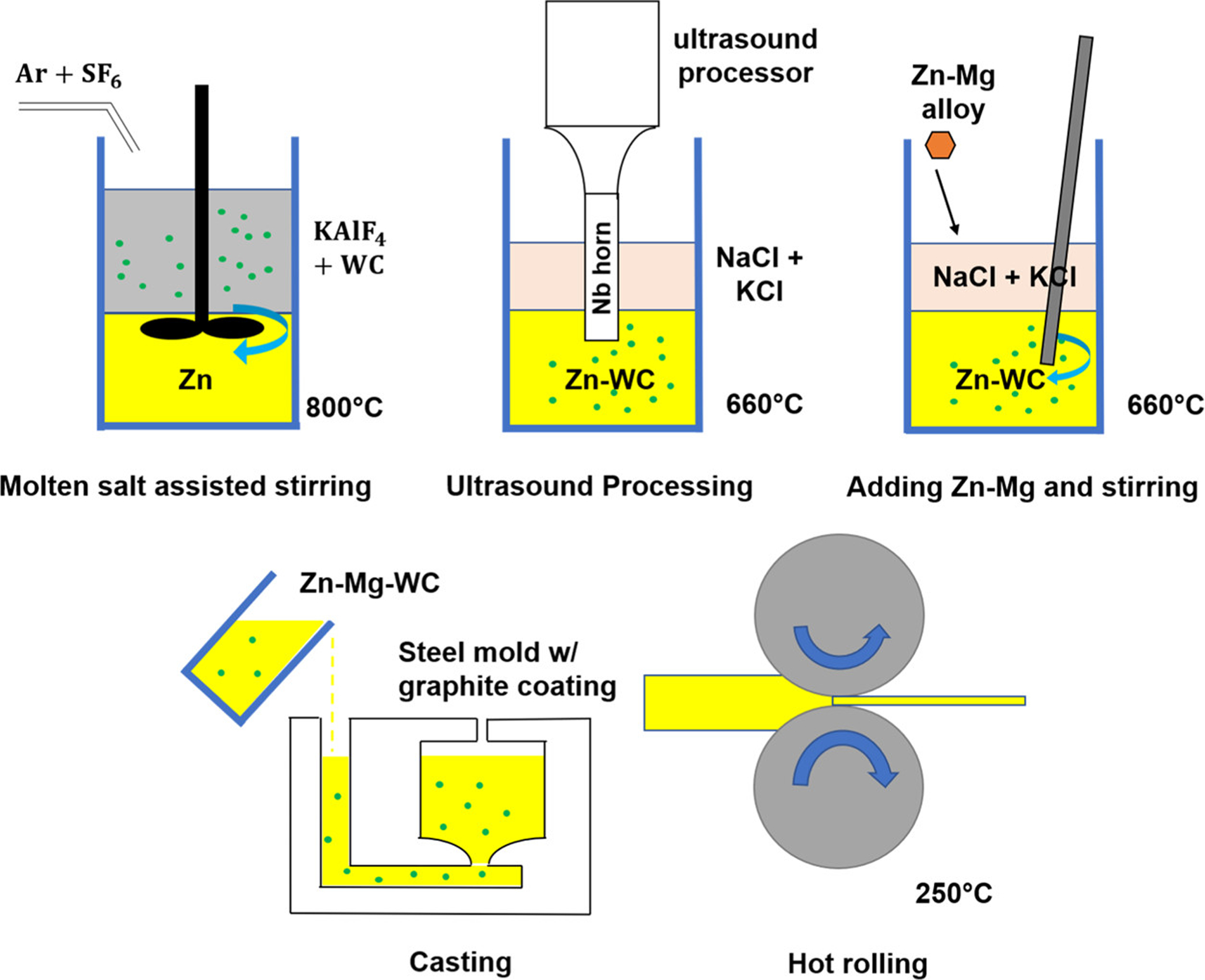
Schematic of the Zn–Mg–WC nanocomposite fabrication process.
2.2. Microstructural Characterization
As-hot-rolled Zn–0.5Mg–WC nanocomposites were prepared by mechanical grinding, alumina nanoparticle polishing, and ion milling for microstructure characterization by ZEISS Supra 40VP scanning electron microscopy (SEM), energy-dispersive X-ray spectroscopy (EDS), electron backscatter diffraction (EBSD), and element detection by X-ray diffraction (XRD). Transmission electron microscopy (TEM) samples of 200 nm thickness Zn–0.5Mg–WC were prepared in a Nova 600 SEM/focused ion beam (FIB) System and were characterized by an FEI T12 cryo-electron microscope. As-cast samples, instead of as-hot-rolled samples, were used in TEM, because as-hot-rolled TEM can hardly be cut by FIB due to the internal residual stress. The nanocomposite samples were ground into chips of a few hundred micrometers and were digested by aqua regia to release metal ions for quantitative element detection using inductively coupled plasma–mass spectrometry (ICP–MS, NexION 2000, PerkinElmer).
The heat capacity of the Zn–0.5Mg–WC nanocomposite and pure Zn–0.5Mg were measured by differential scanning calorimetry (DSC, on a PerkinElmer model) using 100 mg samples with polished surfaces. The temperature ranged from 50 to 500 °C (scan rate: 5 °C/min) under N2 purge protection.
2.3. Mechanical Testing
Wire-electrical discharge machining was used to cut hot-rolled samples into “dog-bone” shapes for tensile testing (ASTM E8/E8M standard sub-size). Tensile tests were carried out using the ElectroPuls E1000 (Instron) mechanical tester at a strain rate of 2 mm/min, and 0.2% proof stress was used as yield strength. Tensile-mode fatigue tests were also conducted using the ElectroPuls E1000 mechanical tester to evaluate the fatigue performance of the Zn–0.5Mg–WC nanocomposite samples. The tests were performed in ambient conditions at a frequency of 60 Hz using a sinusoidal waveform under load control with the stress ratio R = 0.053. The maximum stress was set to 80, 100, 150, and 200% of the yield stress. Cyclical loading was continued for 10 000 000 cycles or until fracture. The frequency dependence of the nanocomposite’s fatigue performance was also evaluated. The tests were performed in ambient conditions using a sinusoidal waveform under load control with the stress ratio R = 0.053. The maximum stress was set to 200% of the yield stress. The frequencies tested were 3, 30, and 60 Hz with cyclical loading continued for 10 000 000 cycles or until fracture at each frequency.
2.4. Immersion Testing
Immersion tests were carried out as previously described. (38) Briefly, each specimen was mechanically polished with SiC abrasive papers down to 1200 grit. The surfaces were cleaned with acetone followed by nano-pure water in an ultrasound bath for 10 min. The immersion solution was oxygenated Hank’s balanced salt solution (1× HBSS; Gibco) that had the pH adjusted to 7.4 using NaOH. At the time of testing, the specimen was immersed in HBSS and kept at 37 °C without stirring, and at each time point (days 1, 3, 5, 7, 10, 14, 17, 21, 23, and 28), aliquots of the immersion medium were collected, and the immersion medium was completely replaced with fresh solution. Because changes in the immersion solution (e.g., accumulation of corrosion products, exhaustion of corrosive electrolytes) can affect the measured CR, the solution volume should be large enough to avoid any appreciable changes. ASTM G31 standard recommends the surface area to volume ratio be a minimum of 0.2 mL/mm2 for a 30-day study. In this study, the surface area to volume ratio used for the test was >1 mL/mm2 and the immersion medium was completely replaced at each time point to mimic sink conditions. The aliquots were filtered (0.22 μm polyvinylidene difluoride membrane) and acidified with nitric acid (final concentration = 5% v/v nitric acid). The ion concentrations of Zn and W in the immersion medium were measured using ICP–MS (PerkinElmer).
2.5. Stent Fabrication and on Bench Deployment
Thin metal sheets (200 μm) of the Zn–0.5Mg–WC nanocomposite were fabricated using hot rolling. A 2-D stent pattern with a strut cross-section of 200 μm × 200 μm was achieved via fiber laser cutting. The stent pattern was based on the close-cell Complete SE Vascular Stent (Medtronic) and modified accordingly to accommodate the mechanical properties of the nanocomposite material. The laser-cut sheet was rolled into a hollow cylinder and the free strut ends were bonded using an epoxy adhesive (Masterbond). The stent was crimped onto a 10 mm × 2 cm Cordis Opta Pro balloon (Cordis Corp., Santa Clara, CA) to an outer diameter of 2 mm. Simulated deployment was carried out on the bench through inflation of the deploying balloon (Supporting Information Video 1).
3. RESULTS AND DISCUSSION
3.1. Tensile Properties
Materials meant to be manufactured into BRS for pediatric patients should have material specifications comparable to those achieved by the current generation of balloon-expandable stents used clinically such as the 316L stainless steel Palmaz Genesis stent (Cordis Corp.). (41–43) Specifically, a successful stent material should have minimum yield strength of 138 MPa, a UTS of at least 245 MPa, and be capable of >20% elongation to failure. The tensile properties of Zn–Mg–WC nanocomposites prepared with a range of Mg concentrations (0–1 wt %) were measured. ICP–MS was used to accurately measure metallic element concentrations (Zn, Mg, and W) post-manufacturing. The Zn–Mg–WC nanocomposites with 2 vol % WC were ground into small pieces, and aqua regia was used to extract elemental Mg and W. The results are shown in Table 1. The corresponding samples were used for tensile property characterization, shown in Figure 2. WC volume fraction was calculated based on the W ion concentration.
Table 1.
Element Concentration of Zn–Mg–WC Samples
| sample no. | Mg (wt %) | WC (vol %) | Zn (wt %) |
|---|---|---|---|
| 1 | 0 | 2.6 | bal. |
| 2 | 0.09 | 1.8 | bal. |
| 3 | 0.20 | 2.3 | bal. |
| 4 | 0.37 | 1.9 | bal. |
| 5 | 0.50 | 2.6 | bal. |
| 6 | 0.69 | 2.2 | bal. |
| 7 | 1.03 | 1.3 | bal. |
Figure 2.
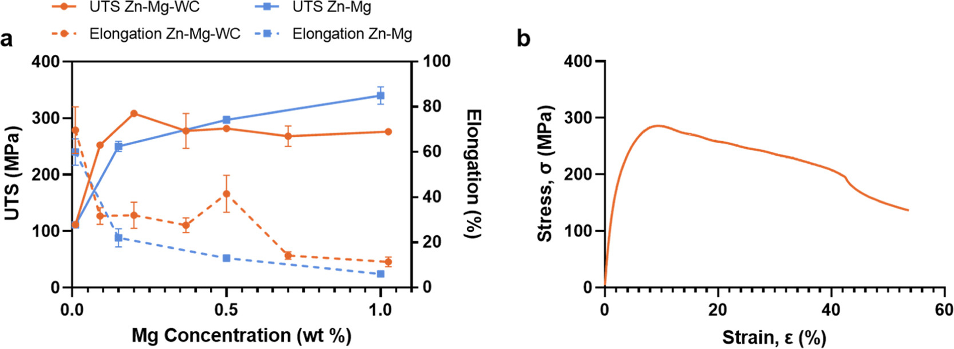
(a) Tensile properties of Zn–Mg–WC nanocomposite vs Mg concentration. Zn–Mg data from published results. (7) (b) Representative stress–strain curve for Zn–0.5Mg–WC nanocomposite.
The corresponding tensile properties for the nanocomposites, including UTS and elongation with respect to the Mg concentration, are shown in Figure 2a and compared to previously published results for pure Zn–Mg samples. (7) Three distinct regions are identified in this figure: (i) when Mg concentration is less than 0.2 wt %, the nanocomposite had a slightly increased UTS with no ductility compensation. This is attributed to the nanoparticle-induced Orowan strengthening and inferior solid solution strengthening. Furthermore, based on previous results for pure Zn matrix nanocomposite, (25) the elongation to failure will not decrease once the WC nanoparticle dispersion is homogeneous. (ii) When Mg concentration is between 0.2 and 0.6 wt %, the UTS of nanocomposite is comparable to the pure alloy’s UTS, but the nanocomposite exhibits greater elongation to failure. In this region, the ductility enhancement is attributed to the nanoparticle’s impact on the intermetallic morphology. Specifically, nanoparticles could assist in engineering the microstructure of the Mg2Zn11 intermetallic phase by modifying from a dendritic to granular morphology to reduce the crack propagation for better ductility. (44) It is worth noting that the nanoparticle-induced Orowan strengthening effect is not obvious in this region because the intermetallic phase dominates the strengthening effect. (iii) When Mg concentration is greater than 0.6 wt %, the elongation is comparable between the pure alloy and the nanocomposite. Because the intermetallic volume fraction is higher than 20%, nanoparticles induced precipitation control is less effective.
The Zn–Mg–WC nanocomposites with 0.5 wt % Mg was selected for additional characterization because it satisfied the minimum strength requirements (UTS = 281.8 ± 2.1 MPa, YS = 119.2 ± 18.0 MPa) and had an elongation to failure of 41.4 ± 7.2% (Figure 2b), which is preferred for materials used for cardiovascular stents. A representative stress–strain diagram is shown in Figure 2b. The results from this study have already outperformed most of the Zn–Mg alloys, but it may not have advantages toward the tensile properties, when compared with most of the recently developed Zn alloys, such as Zn–Li, (45) Zn–Al–Cu–Li, (20) Zn–Mn, (46) which have achieved significantly high strength and ductility comparable with Ti alloys and CoCr alloys. However, BRS devices using a high-strength material with thin strut size may not be ideal because thin strut size may result in the lack of long-term mechanical integrity. More importantly, the abovementioned Zn alloys do not provide a solution for mechanical instability and low fatigue resistance.
3.2. Microstructure
Agglomeration and sintering of WC nanoparticles in the fabrication process could result in non-homogenization and deterioration of the mechanical properties of Zn alloys. With obtaining the optimal tensile properties, as-hot-rolled Zn–0.5Mg–WC was characterized for particle dispersion analysis using SEM with EDS (Figure 3) and under backscattering mode (Figure 4a). The bright phases are WC nanoparticles, and the gray phases indicate the Zn–Mg matrix. A semi-quantitative element analysis in Figure 3 has shown a minor peak of W, because of the low concentration of about 2 vol %, and the peak of Mg cannot be detected because the concentration is about 0.5 wt %. A higher magnification image of the area within the yellow box is shown in Figure 4b. The SEM images show no obvious agglomeration. Furthermore, TEM images (Figure 4c,d) show WC nanoparticles distributed inside the Zn matrix. There was a slight increase in the average WC nanoparticle size following processing (257.96 ± 106.19 nm) (Figure 4e) when compared with the average nanoparticle size in the stock supply (214.80 ± 47.42 nm) (Figure 4f). Additionally, there was greater non-uniformity in nanoparticle size distribution within the nanocomposite suggesting some sintering during the manufacturing process.
Figure 3.
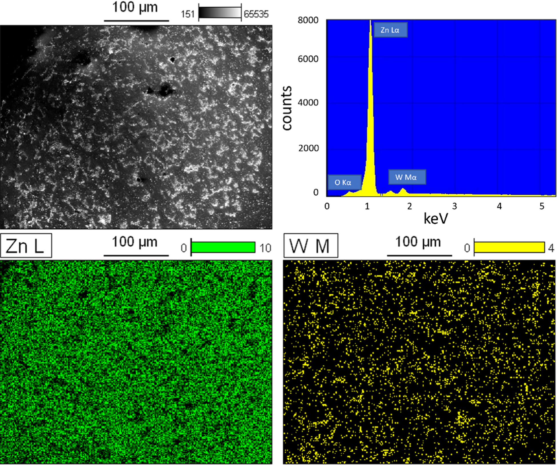
SEM image of Zn–0.5Mg–WC nanocomposite in large scale, with EDS to identify the peaks of Zn (green) and W (yellow).
Figure 4.
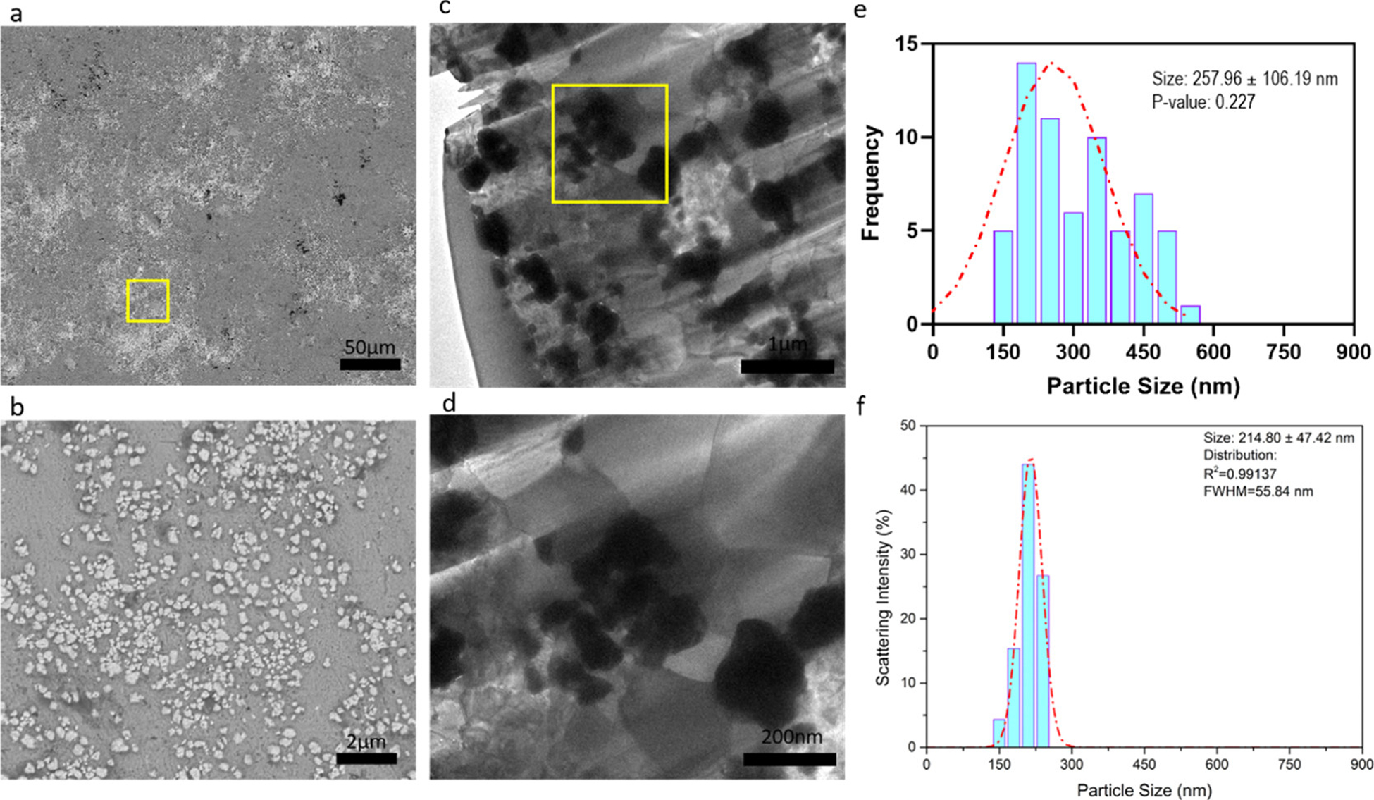
(a) Microstructure of Zn–0.5Mg–WC by SEM. (b) Magnified image of yellow box in (a). (c) TEM image of Zn–0.5Mg–WC. (d) Magnified TEM image of yellow box in (c). (e) WC nanoparticle size distribution measured by ImageJ-particle analysis using TEM image (c). (f) WC nanoparticle size distribution of stock samples, where analysis was performed on SEM images of dispersed nanoparticles.
Due to hot-rolling induced internal stress, TEM samples less than 100 nm thick cannot be prepared; therefore, the Mg2Zn11 phase’s distribution could not be directly observed due to the resolution limitation. However, submicron-sized grain structures were observed in the TEM images in the zones adjacent to the nanoparticles. This confirms the grain refining effect enabled by the WC nanoparticles as nucleation sites and growth confinement. (47) This is also illustrated in a representative EBSD figure of the as-hot rolled Zn–0.5Mg–WC sample (Figure 5a) where nanoparticles are shown as the dark phase. Most of the nanoparticles are found close to grain boundaries, and sub-micron grain size was observed (Figure 5b). α-Zn (Zn-rich phase) of grain size of about 4 μm was observed in regions of low nanoparticle density, due to the non-uniformity locally, which is about the same size in similar research (4.4 μm). (4) The difference to pure Zn–Mg is that the high concentration of nanoparticles in localized areas resulted in regions of sub-micron and nanoscale grain structure. This microstructure is due to both nanoparticle-induced and rolling-induced grain refinement.
Figure 5.
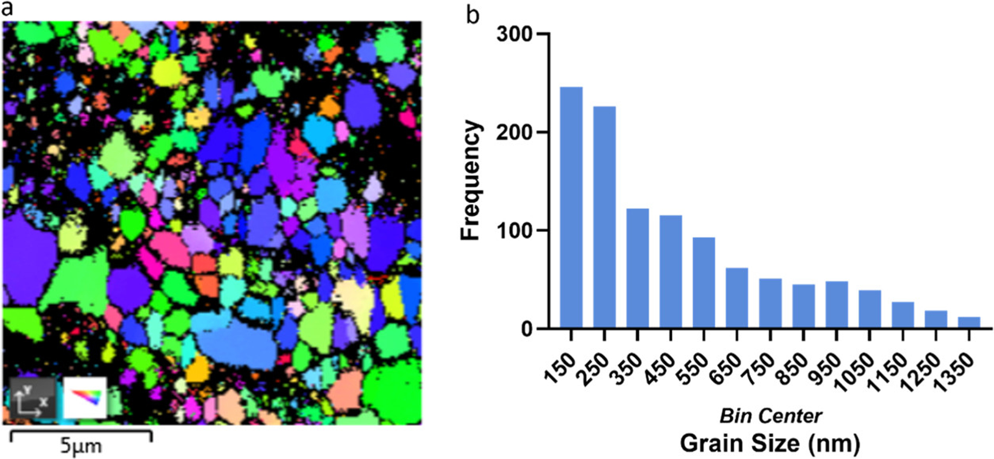
(a) EBSD image analysis of Zn–0.5Mg–WC (b) Zn–Mg matrix grain size distribution.
In addition to the TEM study, SEM/FIB was used to identify the intermetallic phases in Zn–0.5Mg–WC nanocomposites (Figure 6a). The bright phase embodied by solid yellow lines represented the intermetallic phase; the darker background is the Zn-rich phases (α-Zn); WC nanoparticles are indicated in green; grain boundaries refer to the dash yellow line. The intermetallic phase observed in hot extruded/rolled Zn–Mg alloys usually appears as a networked morphology where nucleation and precipitation growth (where Mg migrate out of α-Zn to form intermetallics) typically occurs along the grain boundaries. (4) However, the microstructure observed in this study showed the intermetallic phases with a granular morphology. According to the XRD results in the later section, the intermetallic phases are likely to compose α-Zn, Mg2Zn11, and MgZn2. Additionally, nanoparticles were observed adjacent to the intermetallic phases. Such a phenomenon suggests that WC nanoparticles served as nucleation sites for intermetallic formation instead of grain boundaries. (48) The same sample was characterized again after being immersed in 37 °C silicone oil for three months to evaluate the temperature effect on the microstructure (Figure 6b). The silicone oil bath was used instead of a common simulated body fluid (SBF) to eliminate the influence of the corrosion process, thus individually studying the microstructure evolution at the physiological temperature. WC nanoparticles were observed at the boundaries of Zn–Mg intermetallics, inferring that nanoparticles could serve as blockers to precipitate growth along the grain boundaries. This suggests that the nanocomposite has relatively good thermal stability and that the incorporation of WC nanoparticles improved the material’s thermal stability by controlling the precipitate morphology and growth. In contrast, pure Zn–Mg samples are thermally unstable with significant precipitate growth and age hardening that resulted in a substantial reduction of shelf life. (7)
Figure 6.
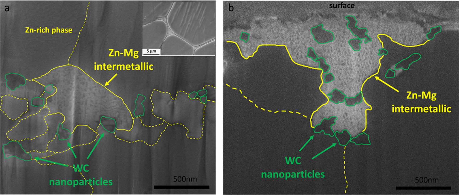
SEM images by FIB, indicating intermetallic morphology of as-hot-rolled Zn–0.5Mg–WC (a) (top right corner is the intermetallic morphology of as-hot-extruded Zn–0.5Mg referenced from ref (4) for comparison) and sample after 3-month immersion in silicone oil (b).
The crystallographic structure and chemical composition of Zn–0.5Mg–WC and Zn–0.5Mg was evaluated by XRD (Figure 7). The Zn–0.5Mg–WC spectrum shows the diffraction peaks of WC, representing (001), (100), and (101), respectively. In addition to the intermetallic phase for Mg2Zn11 (yellow dots), MgZn2 phase (green dots) was also observed in the spectrum, which is uncommon in materials with less than 3 wt % Mg according to the Zn–Mg phase diagram. (49) This unusual phenomenon suggests that the formation of MgZn2 intermetallic phases could attribute to a controlled Mg segregation, possibly enabled by the presence of WC nanoparticles. The relatively high Mg concentration in local zones could be achieved by the preferential Gibbs free energy minimization at the metal matrix–WC interface during the solidification process. (50)
Figure 7.
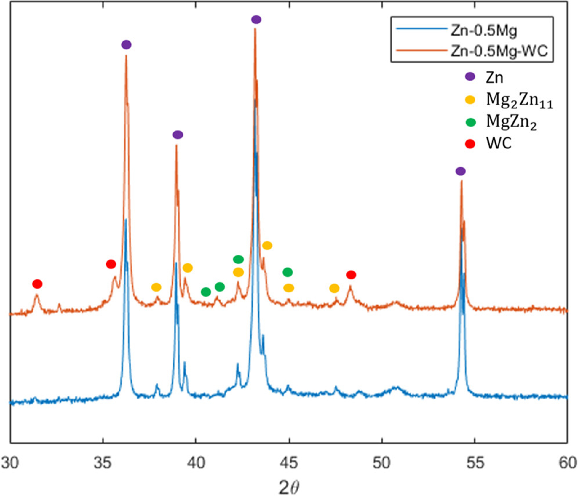
XRD analysis of Zn–0.5Mg–WC and Zn–0.5Mg.
Finally, DSC heat flow measurements were conducted to understand precipitation dynamics during the solidification process (Figure 8). Solidification of Zn-rich phases (hexagonal closest packed) occurred at 419 °C, and solidification of Mg2Zn11 was supposed to occur gradually over a broad temperature range (366.13 to 419.53 °C). (51) However, the heat flow curve for Zn–0.5Mg–WC had an additional peak at 368.9 °C about 50 °C lower than the major peak, representing the solidification of Mg2Zn11. This peak indicates rapid precipitate formation in the presence of WC nanoparticles. This phenomenon suggests at the beginning of solidification there is controlled Mg segregation at the metal matrix–WC interface that acts as nucleation sites with higher free energies. This high Mg concentration lowers the liquidus temperature in these localized regions. As observed via XRD analysis, there was MgZn2 present in the nanocomposite and there was a solidification exothermal peak for Mg2Zn11 in the heat flow curve.
Figure 8.
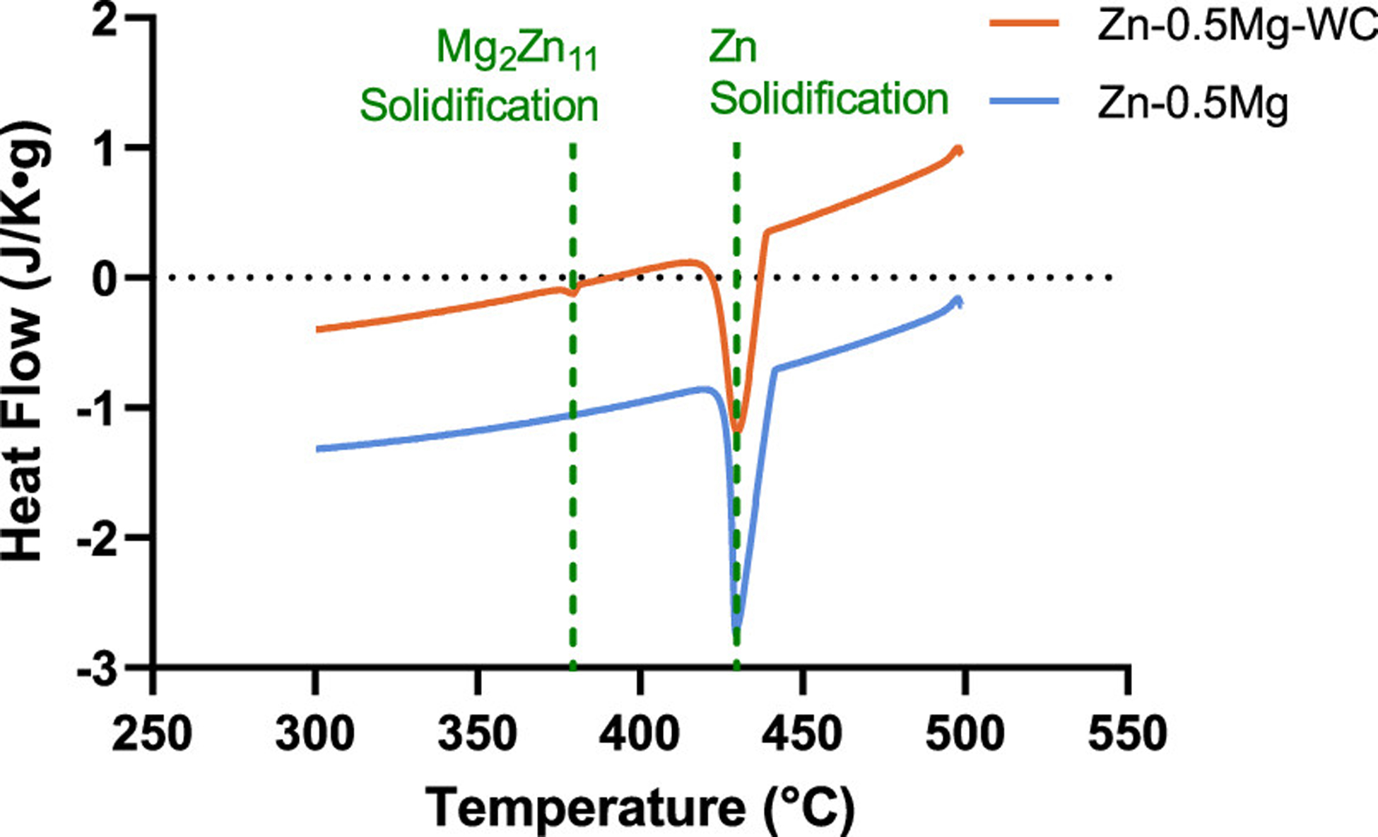
DSC cooling curve of Zn–0.5Mg and Zn–0.5Mg–WC.
The imaging, XRD, and DSC results show that WC nanoparticles participate in both the nucleation and precipitation process to alter the precipitate morphology. A schematic illustration showing the impact of WC nanoparticles is shown in Figure 9. Specifically, the WC nanoparticles caused Mg segregation and served as nucleation sites for intermetallic phase formation and growth instead of the grain boundaries. As a result, the morphology of the intermetallic phase was granular rather than dendritic. Furthermore, the presence of WC nanoparticles at the grain boundaries effectively restricted precipitate growth after work hardening. During precipitation growth, Mg atoms segregated to nanoparticle-adjacent areas instead of the grain boundaries, and the intermetallic precipitates grew isotropically with nanoparticles restraining the growth front. This phenomenon alleviated the material embrittlement and retained the thermal stability and ductility. This effect was confirmed by the experimental result of the material stability in the later section.
Figure 9.
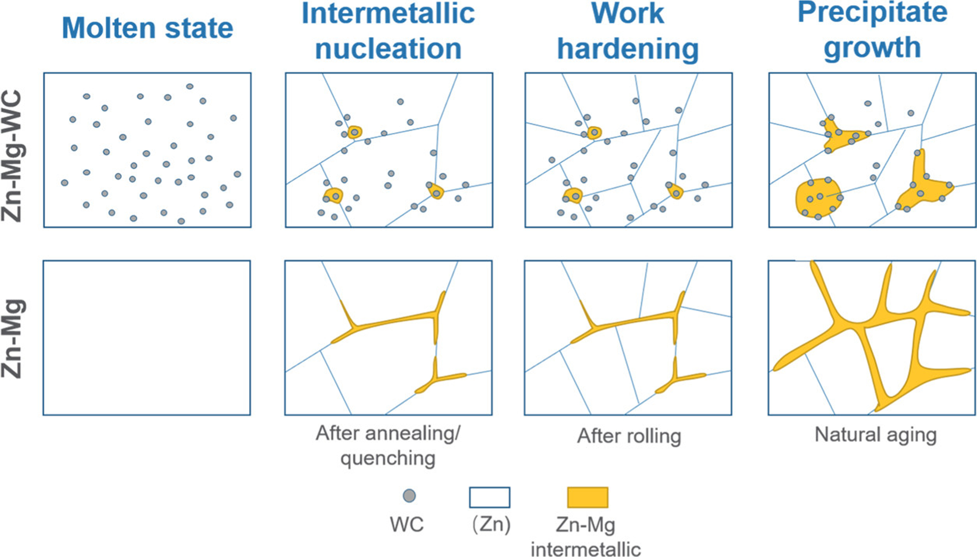
Schematics of Zn–Mg–WC during the manufacturing process to obtain good ductility and enhanced thermal stability, compared with Zn–Mg.
3.3. Fatigue Performance
The fatigue performance of Zn, Zn–0.5Mg, and Zn–0.5Mg–WC are presented in Figure 10a. The results show that (i) alloying Zn with Mg improved fatigue resistance and (ii) the addition of WC nanoparticles to the Zn–Mg alloy further enhances the fatigue resistance. For instance, the Zn–0.5Mg–WC specimen endured maximum stress that was 200% of the mean yield stress, on average, for 4 010 998 cycles while the Zn–0.5Mg specimen survived for 81 935 cycles and pure Zn specimen endured 50 659 cycles. Previous studies have shown that WC nanoparticles have good wettability in molten Zn and are well-dispersed in metal Zn after cooling. (25,38) This helps improve fatigue performance by eliminating defects and porosities that can arise at the particle–matrix when there is insufficient wettability and poor adhesion between the matrix and reinforcing particle. (52) Furthermore, reinforcement particles/fibers in metal matrix composites have been shown to shield the crack tip from the applied stress and reduce the rate of crack growth. (53,54) A similar phenomenon was observed for the Zn–0.5Mg–WC specimen. SEM analysis of the fracture surfaces from the fatigue test samples found that the nanocomposite sample had more dimples on the fracture surfaces when compared to the Zn–0.5Mg and pure Zn samples (Figure 11). Furthermore, WC nanoparticles were observed on the surface where the crack propagation occurred. This suggests that the WC nanoparticles indeed acted as barriers to propagating cracks and decreased the propagation rate.
Figure 10.
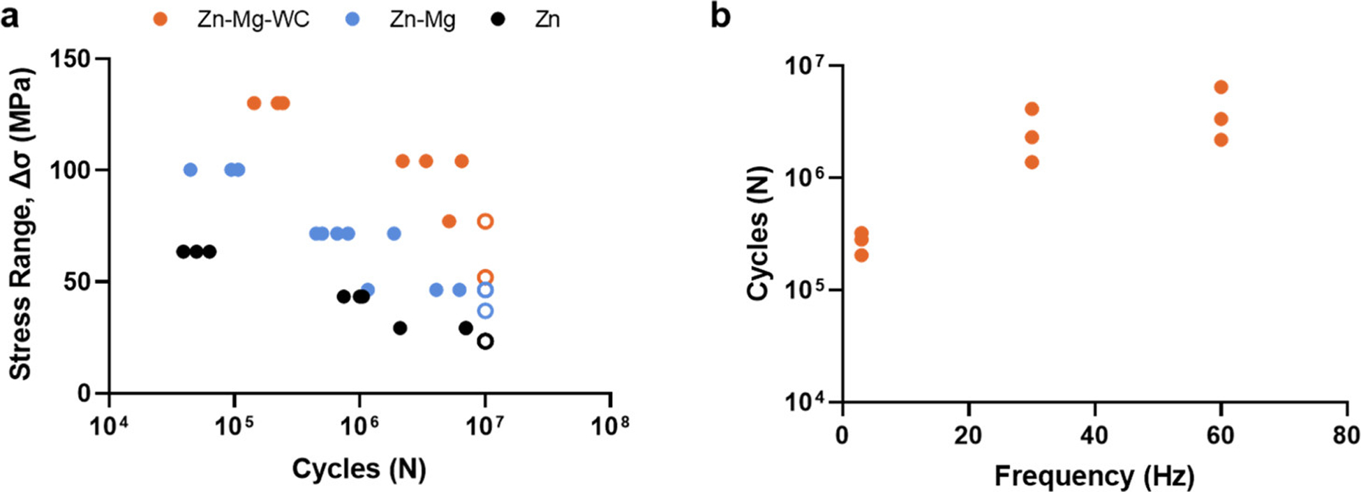
(a) S–N curve of fatigue testing result for Zn, Zn–0.5Mg, and Zn–0.5Mg–WC. (b) Fatigue performance of the Zn–0.5Mg–WC samples exhibits frequency dependence. Samples that did not fail by 10 000 000 cycles are hollow circles (○).
Figure 11.
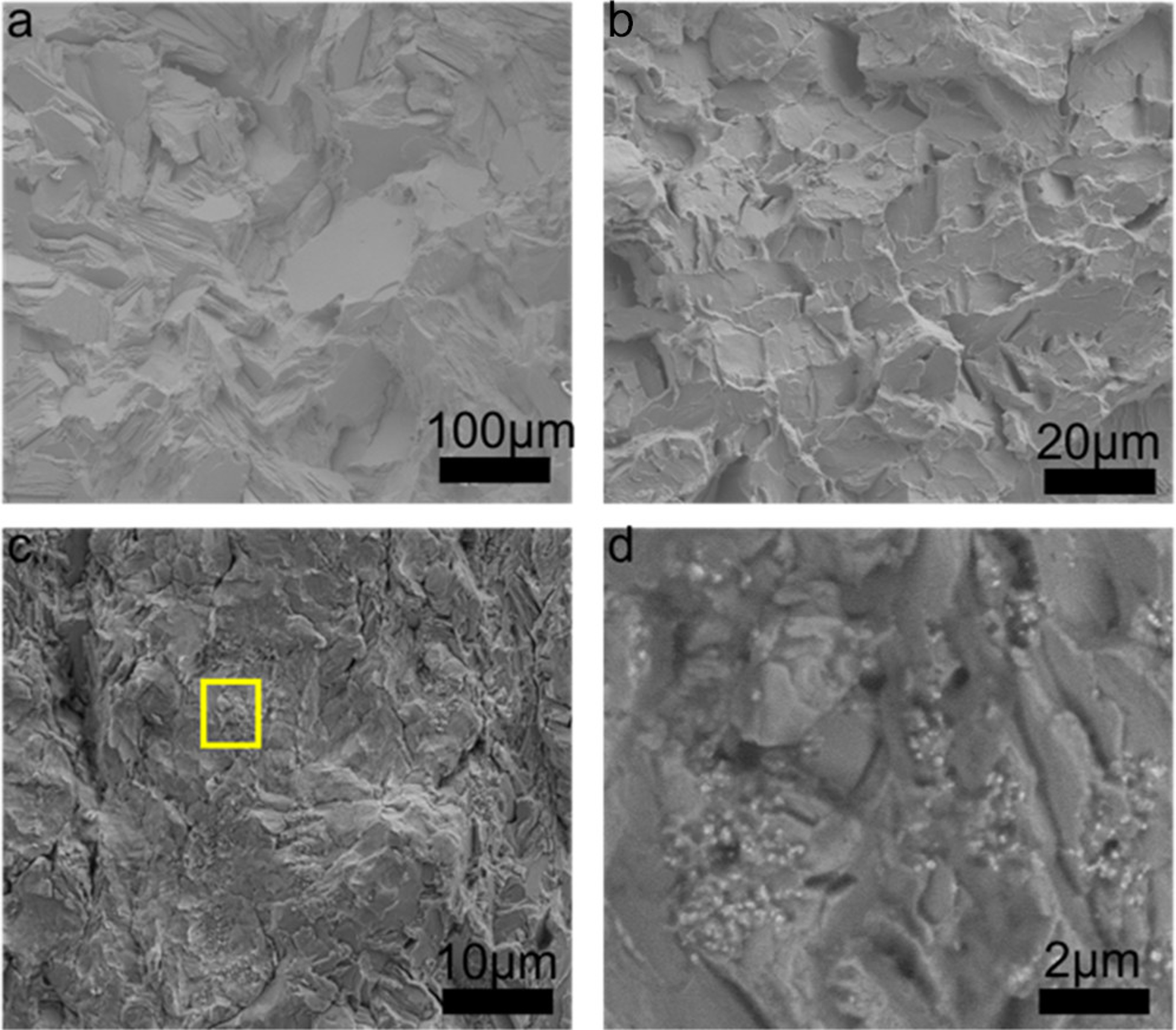
Fatigue fracture surfaces characterized by SEM. (a) Pure Zn, (b) Zn–0.5Mg, (c) Zn–0.5Mg–WC, and (d) magnified image of (c) (yellow square).
Loading frequency also influenced on Zn–0.5Mg–WC fatigue performance: specimens loaded at greater frequencies survived more cycles of loading before failure (Figure 10b). Specifically, the average number of cycles Zn–0.5Mg–WC specimen survived, when cyclically loaded at 3 Hz with the maximum stress set to 200% of the yield stress (R = 0.053), was 269 637 cycles compared to 2 612 168 cycles and 4 010 998 cycles for 30 and 60 Hz, respectively. Few studies have investigated the influence of frequency on fatigue behaviors of Zn alloys, let alone Zn–Mg alloys. (10) However, investigations into the frequency effect on the fatigue behavior of a Zn–Al eutectoid also found an increase in loading frequency reduced the amount of plastic strain at the crack front. (55,56) This suggests dislocation movements in the matrix of Zn alloys are time-dependent. In all cases, the frequencies tested exceed cyclic loading frequencies a BRS would be exposed to during service. The heart rates equivalent to both 30 and 60 Hz are physiologically impossible, while 3 Hz─equivalent to a heart rate of 180 bpm─would be an abnormal, sustained heart rate. Additionally, the radial preload on a cardiovascular stent is expected to lead to more positive R-ratios than the R-ratio studied here, and once deployed, a BRS would not be experiencing cyclical stresses above its yield stress. To more closely reflect the working conditions in vivo, one Zn–0.5Mg–WC specimen was cyclically loaded under ambient conditions at a frequency of 3 Hz using a sinusoidal waveform under load control with maximum stress equal to 80% of the yield stress (R = 0.053). The total run time for the specimen was ~2 months, and it survived 15 million cycles without failing. Overall, these results are promising for Zn–0.5Mg–WC prospects as a BRS material. However, the body’s mechanical environment is more complex with fretting corrosion and immune responses added to cyclic loading. Consequently, investigations into the corrosion and fretting fatigue behavior of these Zn nanocomposites are required to better understand the underlying mechanisms of fatigue failure.
3.4. Thermal Stability
A major obstacle for metals with ultrafine grain structures is their thermal instability, which is directly related to the shelf life. (57) It has been previously shown that nanocrystalline metals have extensive grain growth at room temperature, which negatively impacts the mechanical properties endowed by an ultrafine grain structure. (58) Thermal instability is readily apparent in Zn and Zn alloys because the inherent low melting temperature of Zn (419.53 °C, 692.68 K) results in natural annealing at room temperature. Dispersed nanoparticles have been shown to stabilize ultrafine grains in Cu and Al nanocomposites. (22,24) To investigate the thermal stability of the Zn–0.5Mg–WC nanocomposites, tensile tests were performed on nanocomposites that were immersed in a silicon oil bath at 37 °C for up to three months. As a control, Zn–0.08Mg was used instead of Zn–0.5Mg because the Zn–0.08Mg alloy had initial mechanical properties (i.e., strength and ductility) that were most similar to the Zn–0.5Mg–WC nanocomposite and were closest to meeting the performance requirements for BRS applications. (59) Previous work has shown that the Zn–0.5Mg alloy did not achieve elongation higher than 10% and had greater mechanical strength. (4) Compared with the reported hot-extruded Zn–0.08Mg, which experiences natural age-hardening with rapid loss of ductility, Zn–0.5Mg–WC demonstrated thermal stability by maintaining stable mechanical properties during the 3-month study (Figure 12). The UTS remained in the range of 250–280 MPa, and the elongation to failure was 24–30%. These results showed that Zn–0.5Mg–WC has a longer shelf life than pure Zn–Mg alloys. It suggests that WC nanoparticles can eliminate the grain-growth problem and control the formation of precipitates in Zn–Mg alloys for sustained mechanical properties (i.e., UTS and ductility) at physiological temperatures by instilling the Zener pinning effect to restrict grain growth.
Figure 12.
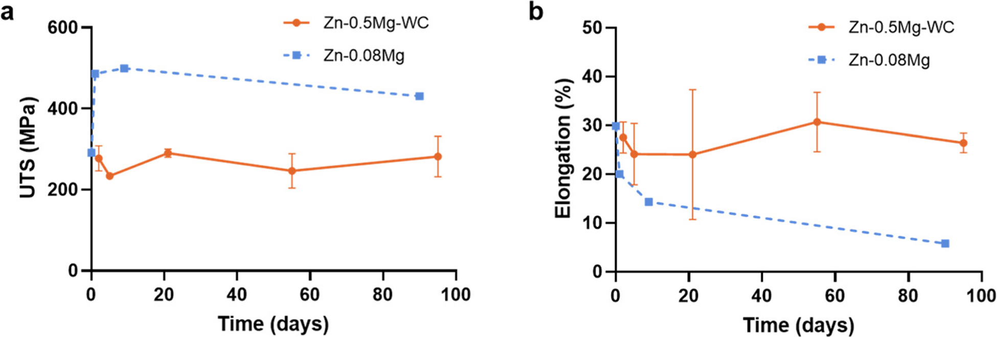
Changes in the (a) UTS and (b) elongation as a function of immersion time. Zn–0.5Mg–WC samples were immersed in silicon oil at 37 °C. Zn–0.08Mg data was acquired from ref (7).
3.5. Immersion
One of the reasons Zn and its alloys are attractive candidates for BRS is because they have a CR compatible with the arterial healing timeline post stenting. (1–3) However, the addition of alloying elements and other impurities (e.g., dispersed nanoparticles) can change the chemical composition, structure, and grain size at the metal surface. This heterogeneity promotes corrosion by creating local regions that act as cathodes and anodes on the same metal surface, and as a result, the CR can be significantly different from that of the pure metal. (60–62) To compare the CRs of Zn, Zn–0.5Mg, and Zn–0.5Mg–WC, samples were immersed in 1× HBSS for four weeks and the ion concentrations of Zn and W in the immersion medium were measured via ICP–MS. Overall, there was no difference in the cumulative Zn ion release between the three different groups (Table 2 and Figure 13). The kinetics appeared to be linear for the duration of the immersion study suggesting a zero-order reaction taking place during the corrosion process. These findings suggest the addition of both WC nanoparticles and a low concentration of Mg should not significantly change the CRs of Zn–Mg–WC nanocomposites when compared to pure Zn and that the nanocomposite should be compatible with the post-stenting arterial healing timeline.
Table 2.
Cumulative Ion Release at Day 28 (n = 4)
| sample | temp. (°C) | Zn (μg/mm2) | W (μg/mm2) | ρ (g/cm3) | CR (mm/y) |
|---|---|---|---|---|---|
| Zn | 37 | 4.04 (±0.42) | N/A | 7.133 | 0.012 (±0.004) |
| Zn–0.5Mg–2WC | 37 | 5.81 (±2.01) | 0.0 (±0.0) | 7.062 | 0.011 (±0.006) |
| Zn–0.5Mg–10WC | 37 | 4.83 (±1.48) | 0.0 (±0.0) | 7.217 | 0.009 (±0.004) |
Figure 13.
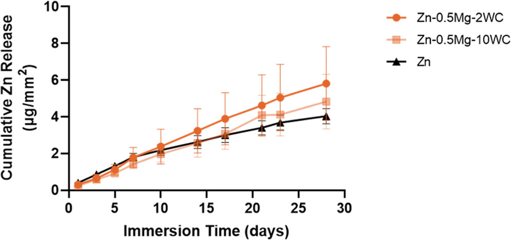
Cumulative Zn ion release in an immersion period of 28 days in a SBF (Hank’s balanced salt solution) at 37 °C. Zn–0.5Mg–WC has indicated a similar CR as pure Zn manufactured in the same method.
CRs based on immersion testing were calculated according to ASTM G31. Briefly, the ICP–MS data was used to calculate CR in mm/y using eq 1
| (1) |
where K is the CR constant 8.76 × 10⁴, m is mass loss (g), A is exposed surface area (cm2), t is time (h), and ρ is the density (g/cm3). The theoretical densities of the nanocomposites were calculated using the mixture rule. The CRs reported in Table 2 are averaged over the four-week test. For all three sample types, the calculated CR was ~0.01 mm/y. These values may underestimate the CR because any released ions that formed insoluble corrosion products were not accounted for in the calculation. However, little-to-no insoluble products are likely on the samples since they yielded linear Zn ion release versus time plots and insoluble corrosion products would have formed a barrier to the electrochemical reactions causing corrosion. Importantly, in vitro tests fail to fully recapitulate the corrosive environment BRS are exposed to during service in vivo. Still, these in vitro results suggest the Zn–0.5Mg–WC nanocomposite should satisfy the degradation rate criteria of <0.02 mm/y for BRS. (4)
Encouragingly, no W ions were released after 28 days as measured by ICP–MS with a lower quantifiable limit of 0.5 ppb. Currently, there are no minimal risk levels that have been derived for W and it is generally considered to be an inert metal. Still, occupational exposure limits have been set at 1 ppm for soluble W compounds for up to 10 h work exposure by the National Institute for Occupational Safety and Health (NIOSH) and the Occupational Safety and Health Administration (OSHA). However, in clinical applications, it is more likely that cells will encounter WC nanoparticles over elemental W. Previous studies have found that tungsten carbide nanoparticles could enter various cell types, (27,63) but do not yield a toxic response. It is worth noting that these studies only looked at short-term exposure (<3 days) and no in vivo studies have been performed to date. As such, no biodistribution data are available, and minimal risk levels have not been derived. However, taken altogether, the toxic potential of the tungsten and tungsten carbide nanoparticles released from a stent made of Zn–0.5Mg–WC are expected to be negligible.
3.6. Stent Fabrication and Bench Testing
A closed-cell stent prototype with a 200 μm strut size made from fiber laser cut Zn–0.5Mg–WC nanocomposite sheet is shown in Figure 14. Bench testing was carried out at room temperature, and a video of the stent deployment is available in the Supporting Information. It shows the stent was crimped onto a flat balloon followed by reducing to an outer diameter of 2 mm. Then, as the balloon was inflated, the stent prototype was deployed uniformly to an outer diameter of 10 mm. It was observed that the recoil was less than 5% and there was no fracturing during the deployment process. The reduced stent recoil is benefited from the enhanced Young’s modulus caused by nanoparticle strengthening. The bench testing provides further evidence that the Zn–0.5Mg–WC nanocomposite satisfies the material requirements for stenting applications. However, in vitro bench testing does not fully account for all the challenges associated with in vivo stent deployment, and these results must be confirmed in a large animal model.
Figure 14.
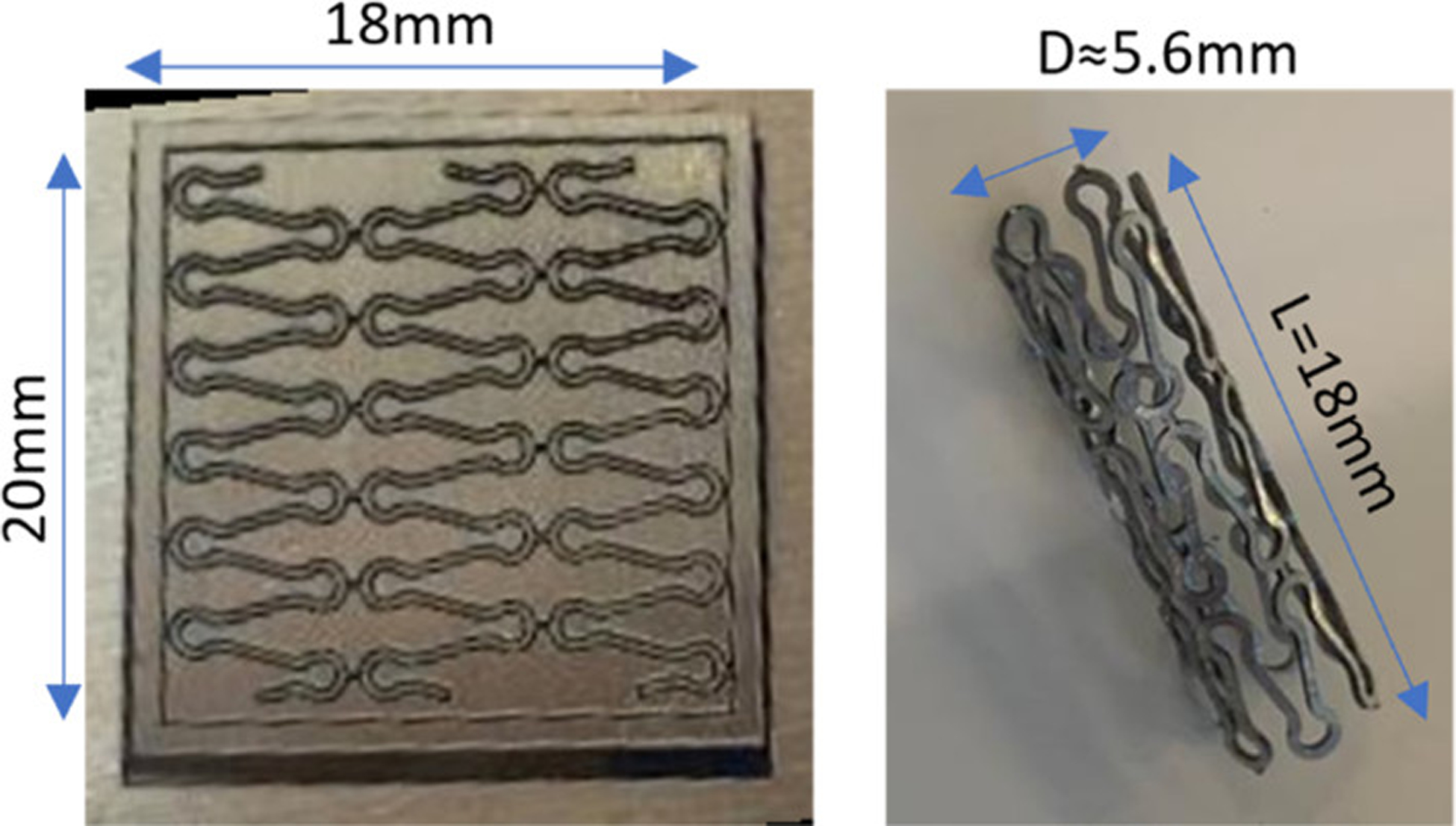
Thin sheet metal Zn–0.5Mg–WC after laser cutting (left) and the cut pattern was rolled and bonded to stent prototype (right).
4. CONCLUSIONS
In this study, Zn–0.5Mg–WC nanocomposite was comprehensively evaluated for its suitability as a material for high-stress BRS applications (e.g., aortic stenting) in pediatric patients. The results showed that the Zn–0.5Mg–WC nanocomposite had excellent mechanical strength (UTS > 250 MPa), elongation to failure (>30%), and a suitable CR (~0.02 mm/y) for this clinical application. Although the tensile performance cannot outperform some of the biocompatible Zn alloys, the presence of WC nanoparticles provided the Zn–Mg alloy with enhanced fatigue resistance and thermal stability for prolonged shelf life, which has not yet been achieved by others. Nanocomposites could overcome the thermal instability obstacle caused by age hardening, and retain their mechanical properties during storage, implantation, and service. Preliminary bench testing of stent prototypes shows the nanocomposite is capable of surviving deployment. However, in vivo studies in a large animal model are required to validate both the biocompatibility as well as the efficacy of the Zn–0.5Mg–WC nanocomposite as a BRS material. Considering the scalable fabrication of cardiovascular stent, hot tube extrusion will be required in the fabrication for better quality control. Overall, a safe and efficacious BRS to treat pediatric arterial obstructions would revolutionize the field by eliminating the need for open-chest surgeries in infants and older children.
Supplementary Material
ACKNOWLEDGEMENTS
The research reported in this publication was supported by the National Heart, Lung, and Blood Institute of the National Institutes of Health under award number R01 HL143465. The content is solely the responsibility of the authors and does not necessarily represent the official views of the National Institutes of Health. The authors acknowledge Dr. Chong Hyun (Paul) Chang, University of California Center for Environmental Implications of Nanotechnology (UC-CEIN), University of California, Los Angeles (UCLA), for his help with the ICP-MS data acquisition.
REFERENCES
- 1.Bowen PK; Drelich J; Goldman J Zinc exhibits ideal physiological corrosion behavior for bioabsorbable stents. Adv. Mater 2013, 25, 2577–2582, DOI: 10.1002/adma.201300226. [DOI] [PubMed] [Google Scholar]
- 2.Drelich AJ; Zhao S; Guillory RJ II; Drelich JW; Goldman J Long-term surveillance of zinc implant in murine artery: surprisingly steady biocorrosion rate. Acta Biomater. 2017, 58, 539–549, DOI: 10.1016/j.actbio.2017.05.045. [DOI] [PMC free article] [PubMed] [Google Scholar]
- 3.Yang H; Wang C; Liu C; Chen H; Wu Y; Han J; Jia Z; Lin W; Zhang D; Li W; Yuan W; Guo H; Li H; Yang G; Kong D; Zhu D; Takashima K; Ruan L; Nie J; Li X; Zheng Y Evolution of the degradation mechanism of pure zinc stent in the one-year study of rabbit abdominal aorta model. Biomaterials 2017, 145, 92–105, DOI: 10.1016/j.biomaterials.2017.08.022. [DOI] [PubMed] [Google Scholar]
- 4.Mostaed E; Sikora-Jasinska M; Mostaed A; Loffredo S; Demir AG; Previtali B; Mantovani D; Beanland R; Vedani M Novel Zn-based alloys for biodegradable stent applications: design, development and in vitro degradation. J. Mech. Behav. Biomed. Mater 2016, 60, 581–602, DOI: 10.1016/j.jmbbm.2016.03.018. [DOI] [PubMed] [Google Scholar]
- 5.Wang L-Q; Ren Y-P; Sun S-N; Zhao H; Li S; Qin G-W Microstructure, Mechanical Properties and Fracture Behavior of As-Extruded Zn–Mg Binary Alloys. Acta Metall. Sin. (Engl. Lett.) 2017, 30, 931–940, DOI: 10.1007/s40195-017-0585-4. [DOI] [Google Scholar]
- 6.Fu J; Su Y; Qin Y-X; Zheng Y; Wang Y; Zhu D Evolution of metallic cardiovascular stent materials: a comparative study among stainless steel, magnesium and zinc. Biomaterials 2020, 230, 119641, DOI: 10.1016/j.biomaterials.2019.119641. [DOI] [PMC free article] [PubMed] [Google Scholar]
- 7.Jin H; Zhao S; Guillory R; Bowen PK; Yin Z; Griebel A; Schaffer J; Earley EJ; Goldman J; Drelich JW Novel high-strength, low-alloys Zn-Mg (< 0.1 wt% Mg) and their arterial biodegradation. Mater. Sci. Eng., C 2018, 84, 67–79, DOI: 10.1016/j.msec.2017.11.021. [DOI] [PMC free article] [PubMed] [Google Scholar]
- 8.Mostaed E; Sikora-Jasinska M; Drelich JW; Vedani M Zinc-based alloys for degradable vascular stent applications. Acta Biomater. 2018, 71, 1–23, DOI: 10.1016/j.actbio.2018.03.005. [DOI] [PMC free article] [PubMed] [Google Scholar]
- 9.Pachla W; Przybysz S; Jarzębska A; Bieda M; Sztwiertnia K; Kulczyk M; Skiba J Structural and mechanical aspects of hypoeutectic Zn–Mg binary alloys for biodegradable vascular stent applications. Bioact. Mater 2021, 6, 26–44, DOI: 10.1016/j.bioactmat.2020.07.004. [DOI] [PMC free article] [PubMed] [Google Scholar]
- 10.Li G; Yang H; Zheng Y; Chen X-H; Yang J-A; Zhu D; Ruan L; Takashima K Challenges in the use of zinc and its alloys as biodegradable metals: perspective from biomechanical compatibility. Acta Biomater. 2019, 97, 23–45, DOI: 10.1016/j.actbio.2019.07.038. [DOI] [PubMed] [Google Scholar]
- 11.Venezuela JJD; Johnston S; Dargusch MS The prospects for biodegradable zinc in wound closure applications. Adv. Healthcare Mater 2019, 8, 1900408, DOI: 10.1002/adhm.201900408. [DOI] [PubMed] [Google Scholar]
- 12.Liu S; Zhan H; Kent D; Tan Q; Yin Y; Doan N; Wang C; Dargusch M; Wang G Effect of Mg on dynamic recrystallization of Zn–Mg alloys during room-temperature compression. Mater. Sci. Eng., A 2021, 830, 142243, DOI: 10.1016/j.msea.2021.142243. [DOI] [Google Scholar]
- 13.Li HF; Shi ZZ; Wang LN Opportunities and challenges of biodegradable Zn-based alloys. J. Mater. Sci. Technol 2020, 46, 136–138, DOI: 10.1016/j.jmst.2019.12.014. [DOI] [Google Scholar]
- 14.Ardakani MS; Mostaed E; Sikora-Jasinska M; Kampe SL; Drelich JW The effects of alloying with Cu and Mn and thermal treatments on the mechanical instability of Zn-0.05 Mg alloy. Mater. Sci. Eng., A 2020, 770, 138529, DOI: 10.1016/j.msea.2019.138529. [DOI] [PMC free article] [PubMed] [Google Scholar]
- 15.Mostaed E; Sikora-Jasinska M; Ardakani MS; Mostaed A; Reaney IM; Goldman J; Drelich JW Towards revealing key factors in mechanical instability of bioabsorbable Zn-based alloys for intended vascular stenting. Acta Biomater. 2020, 105, 319–335, DOI: 10.1016/j.actbio.2020.01.028. [DOI] [PMC free article] [PubMed] [Google Scholar]
- 16.Chen C; Yue R; Zhang J; Huang H; Niu J; Yuan G Biodegradable Zn-1.5 Cu-1.5 Ag alloy with anti-aging ability and strain hardening behavior for cardiovascular stents. Mater. Sci. Eng., C 2020, 116, 111172, DOI: 10.1016/j.msec.2020.111172. [DOI] [PubMed] [Google Scholar]
- 17.Katsumiti A; Gilliland D; Arostegui I; Cajaraville MP Mechanisms of toxicity of Ag nanoparticles in comparison to bulk and ionic Ag on mussel hemocytes and gill cells. PLoS One 2015, 10, e0129039 DOI: 10.1371/journal.pone.0129039. [DOI] [PMC free article] [PubMed] [Google Scholar]
- 18.Igbokwe IO; Igwenagu E; Igbokwe NA Aluminium toxicosis: a review of toxic actions and effects. Interdiscip. Toxicol 2019, 12, 45, DOI: 10.2478/intox-2019-0007. [DOI] [PMC free article] [PubMed] [Google Scholar]
- 19.Meng H; Chen Z; Xing G; Yuan H; Chen C; Zhao F; Zhang C; Zhao Y Ultrahigh reactivity provokes nanotoxicity: explanation of oral toxicity of nano-copper particles. Toxicol. Lett 2007, 175, 102–110, DOI: 10.1016/j.toxlet.2007.09.015. [DOI] [PubMed] [Google Scholar]
- 20.Farabi E; Sharp J; Vahid A; Wang J; Fabijanic DM; Barnett MR; Gallo SC Novel Biodegradable Zn Alloy with Exceptional Mechanical and In Vitro Corrosion Properties for Biomedical Applications. ACS Biomater. Sci. Eng 2021, 7, 5555–5572, DOI: 10.1021/acsbiomaterials.1c00763. [DOI] [PubMed] [Google Scholar]
- 21.Biermann H; Kemnitzer M; Hartmann O On the temperature dependence of the fatigue and damage behaviour of a particulate-reinforced metal-matrix composite. Mater. Sci. Eng., A 2001, 319–321, 671–674, DOI: 10.1016/s0921-5093(00)02031-1. [DOI] [Google Scholar]
- 22.Lin T-C; Cao C; Sokoluk M; Jiang L; Wang X; Schoenung JM; Lavernia EJ; Li X Aluminum with dispersed nanoparticles by laser additive manufacturing. Nat. Commun 2019, 10, 4124, DOI: 10.1038/s41467-019-12047-2. [DOI] [PMC free article] [PubMed] [Google Scholar]
- 23.Martin JH; Yahata BD; Hundley JM; Mayer JA; Schaedler TA; Pollock TM 3D printing of high-strength aluminium alloys. Nature 2017, 549, 365, DOI: 10.1038/nature23894. [DOI] [PubMed] [Google Scholar]
- 24.Cao C; Yao G; Jiang L; Sokoluk M; Wang X; Ciston J; Javadi A; Guan Z; De Rosa I; Xie W; Lavernia EJ; Schoenung JM; Li X Bulk ultrafine grained/nanocrystalline metals via slow cooling. Sci. Adv 2019, 5, eaaw2398 DOI: 10.1126/sciadv.aaw2398. [DOI] [PMC free article] [PubMed] [Google Scholar]
- 25.Guan Z; Linsley CS; Hwang I; Yao G; Wu BM; Li X Novel zinc/tungsten carbide nanocomposite as bioabsorbable implant. Mater. Lett 2020, 263, 127282, DOI: 10.1016/j.matlet.2019.127282. [DOI] [PMC free article] [PubMed] [Google Scholar]
- 26.Guan Z; Yao G; Zeng Y; Li X Fabrication and characterization of in situ Zn-TiB2 nanocomposite. Procedia Manuf. 2020, 48, 332–337, DOI: 10.1016/j.promfg.2020.05.055. [DOI] [PMC free article] [PubMed] [Google Scholar]
- 27.Bastian S; Busch W; Kühnel D; Springer A; Meißner T; Holke R; Scholz S; Iwe M; Pompe W; Gelinsky M Toxicity of Tungsten Carbide and Cobalt-Doped Tungsten Carbide Nanoparticles in Mammalian Cells In Vitro; National Institute of Environmental Health Sciences, 2009. [DOI] [PMC free article] [PubMed] [Google Scholar]
- 28.Kühnel D; Busch W; Meißner T; Springer A; Potthoff A; Richter V; Gelinsky M; Scholz S; Schirmer K Agglomeration of tungsten carbide nanoparticles in exposure medium does not prevent uptake and toxicity toward a rainbow trout gill cell line. Aquat. Toxicol 2009, 93, 91–99, DOI: 10.1016/j.aquatox.2009.04.003. [DOI] [PubMed] [Google Scholar]
- 29.Lanone S; Rogerieux F; Geys J; Dupont A; Maillot-Marechal E; Boczkowski J; Lacroix G; Hoet P Comparative toxicity of 24 manufactured nanoparticles in human alveolar epithelial and macrophage cell lines. Part. Fibre Toxicol 2009, 6, 14, DOI: 10.1186/1743-8977-6-14. [DOI] [PMC free article] [PubMed] [Google Scholar]
- 30.Wang W-Q; Liang D-K; Yang D-Z; Qi M Analysis of the transient expansion behavior and design optimization of coronary stents by finite element method. J. Biomech 2006, 39, 21–32, DOI: 10.1016/j.jbiomech.2004.11.003. [DOI] [PubMed] [Google Scholar]
- 31.Timmins LH; Moreno MR; Meyer CA; Criscione JC; Rachev A; Moore JE Stented artery biomechanics and device design optimization. Med. Biol. Eng. Comput 2007, 45, 505–513, DOI: 10.1007/s11517-007-0180-3. [DOI] [PubMed] [Google Scholar]
- 32.Auricchio F; Constantinescu A; Conti M; Scalet G Fatigue of metallic stents: from clinical evidence to computational analysis. Ann. Biomed. Eng 2016, 44, 287–301, DOI: 10.1007/s10439-015-1447-8. [DOI] [PubMed] [Google Scholar]
- 33.Erbel R; Di Mario C; Bartunek J; Bonnier J; de Bruyne B; Eberli FR; Erne P; Haude M; Heublein B; Horrigan M; Ilsley C; Böse D; Koolen J; Lüscher TF; Weissman N; Waksman R Temporary scaffolding of coronary arteries with bioabsorbable magnesium stents: a prospective, non-randomised multicentre trial. Lancet 2007, 369, 1869–1875, DOI: 10.1016/s0140-6736(07)60853-8. [DOI] [PubMed] [Google Scholar]
- 34.Werkhoven RJ; Sillekens WH; Van Lieshout JBJM Processing aspects of magnesium alloy stent tube. In Magnesium Technology 2011; Springer, 2011, pp 419–424. DOI: 10.1002/9781118062029.ch79. [DOI] [Google Scholar]
- 35.Yamamoto M; Watanabé J Fatigue properties of zinc single crystals and polycrystals. J. Phys. Soc. Jpn 1960, 15, 2099, DOI: 10.1143/jpsj.15.2099. [DOI] [Google Scholar]
- 36.Shin SE; Bae DH Fatigue behavior of Al2024 alloy-matrix nanocomposites reinforced with multi-walled carbon nanotubes. Composites, Part B 2018, 134, 61–68, DOI: 10.1016/j.compositesb.2017.09.034. [DOI] [Google Scholar]
- 37.Malaki M; Tehrani AF; Niroumand B Fatigue behavior of aluminum/magnesium matrix composites and nanocomposites. Ceram. Int 2020, 46, 23326–23336, DOI: 10.1016/j.ceramint.2020.06.246. [DOI] [Google Scholar]
- 38.Guan Z; Linsley CS; Pan S; DeBenedetto C; Liu J; Wu BM; Li X Highly Ductile Zn-2Fe-WC Nanocomposite as Biodegradable Material. Metall. Mater. Trans. A 2020, 51, 4406–4413, DOI: 10.1007/s11661-020-05878-y. [DOI] [PMC free article] [PubMed] [Google Scholar]
- 39.Coleman DS; Lacy PDA The phase equilibrium diagram for the KCl-NaCl system. Mater. Res. Bull 1967, 2, 935–938, DOI: 10.1016/0025-5408(67)90149-3. [DOI] [Google Scholar]
- 40.Zhao S; McNamara CT; Bowen PK; Verhun N; Braykovich JP; Goldman J; Drelich JW Structural characteristics and in vitro biodegradation of a novel Zn-Li alloy prepared by induction melting and hot rolling. Metall. Mater. Trans. A 2017, 48, 1204–1215, DOI: 10.1007/s11661-016-3901-0. [DOI] [Google Scholar]
- 41.Radtke WAK; Waller BR; Hebra A; Bradley SM Palliative stent implantation for aortic coarctation in premature infants weighing< 1,500 g. Am. J. Cardiol 2002, 90, 1409–1412, DOI: 10.1016/s0002-9149(02)02887-4. [DOI] [PubMed] [Google Scholar]
- 42.Sreeram N; Sreeram I; Bennink G Palliative stent implantation for coarctation in neonates and young infants. Ann. Pediatr. Cardiol 2012, 5, 145, DOI: 10.4103/0974-2069.99616. [DOI] [PMC free article] [PubMed] [Google Scholar]
- 43.Mohan UR; Danon S; Levi D; Connolly D; Moore JW Stent implantation for coarctation of the aorta in children< 30 kg. JACC: Cardiovasc. Interv 2009, 2, 877–883, DOI: 10.1016/j.jcin.2009.07.002. [DOI] [PubMed] [Google Scholar]
- 44.Jiao ZB; Luan JH; Liu CT Strategies for improving ductility of ordered intermetallics. Prog. Nat. Sci.: Mater. Int 2016, 26, 1–12, DOI: 10.1016/j.pnsc.2016.01.014. [DOI] [Google Scholar]
- 45.Yang H; Jia B; Zhang Z; Qu X; Li G; Lin W; Zhu D; Dai K; Zheng Y Alloying design of biodegradable zinc as promising bone implants for load-bearing applications. Nat. Commun 2020, 11, 401, DOI: 10.1038/s41467-019-14153-7. [DOI] [PMC free article] [PubMed] [Google Scholar]
- 46.Jia B; Yang H; Han Y; Zhang Z; Qu X; Zhuang Y; Wu Q; Zheng Y; Dai K In vitro and in vivo studies of Zn-Mn biodegradable metals designed for orthopedic applications. Acta Biomater. 2020, 108, 358–372, DOI: 10.1016/j.actbio.2020.03.009. [DOI] [PubMed] [Google Scholar]
- 47.Wang K; Jiang HY; Wang QD; Ye B; Ding WJ Nanoparticle-induced nucleation of eutectic silicon in hypoeutectic Al-Si alloy. Mater. Charact 2016, 117, 41–46, DOI: 10.1016/j.matchar.2016.04.016. [DOI] [Google Scholar]
- 48.Rasooli A; Safavi MS; Hokmabad MK Cr2O3 nanoparticles: A promising candidate to improve the mechanical properties and corrosion resistance of Ni-Co alloy coatings. Ceram. Int 2018, 44, 6466–6473, DOI: 10.1016/j.ceramint.2018.01.044. [DOI] [Google Scholar]
- 49.Yao C; Wang Z; Tay SL; Zhu T; Gao W Effects of Mg on microstructure and corrosion properties of Zn–Mg alloy. J. Alloys Compd 2014, 602, 101–107, DOI: 10.1016/j.jallcom.2014.03.025. [DOI] [Google Scholar]
- 50.Pan S; Guan Z; Yao G; Yuan J; Li X Mo-enhanced chemical stability of TiC nanoparticles in molten Al. J. Alloys Compd 2021, 856, 158169, DOI: 10.1016/j.jallcom.2020.158169. [DOI] [Google Scholar]
- 51.Erol M; Keşlioğlu K; Maraşli N Solid–liquid interfacial energy of the solid Mg2Zn11 phase in equilibrium with Zn–Mg eutectic liquid. J. Phys.: Condens. Matter 2007, 19, 176003, DOI: 10.1088/0953-8984/19/17/176003. [DOI] [PubMed] [Google Scholar]
- 52.Malaki M; Tehrani AF; Niroumand B Fatgiue behavior of metal matrix nanocomposites. Ceram. Int 2020, 46, 23326–23336, DOI: 10.1016/j.ceramint.2020.06.246. [DOI] [Google Scholar]
- 53.Kaynak C; Boylu S Effects of SiC particulates on the fatigue behaviour of an Al-alloy matrix composite. Mater. Des 2006, 27, 776–782, DOI: 10.1016/j.matdes.2005.01.009. [DOI] [Google Scholar]
- 54.Walls DP; Bao G; Zok FW Mode I fatigue cracking in a fiber reinforced metal matrix composite. Acta Metall. Mater 1993, 41, 2061–2071, DOI: 10.1016/0956-7151(93)90375-3. [DOI] [Google Scholar]
- 55.Woodthorpe J; Pearce R Fatigue behaviour of a commercial zinc-aluminium eutectoid alloy. Int. J. Mech. Sci 1974, 16, 699–705, DOI: 10.1016/0020-7403(74)90096-4. [DOI] [Google Scholar]
- 56.Woodthorpe J; Pearce R Microstructural observations on the frequency effect in the fatigue behaviour of superplastic Zn-Al eutectoid. Met. Sci 1977, 11, 103–108, DOI: 10.1179/msc.1977.11.3.103. [DOI] [Google Scholar]
- 57.Gibson MA Segregation and Embrittlement in Metallic Interfaces: Bounds, Models, and Trends; Massachusetts Institute of Technology, 2016. [Google Scholar]
- 58.Andrievski RA Review of thermal stability of nanomaterials. J. Mater. Sci 2014, 49, 1449–1460, DOI: 10.1007/s10853-013-7836-1. [DOI] [Google Scholar]
- 59.Dutta M; Halder AK; Singh SB Morphology and properties of hot dip Zn–Mg and Zn–Mg–Al alloy coatings on steel sheet. Surf. Coat. Technol 2010, 205, 2578–2584, DOI: 10.1016/j.surfcoat.2010.10.006. [DOI] [Google Scholar]
- 60.Liu L; Gebresellasie K; Collins B; Zhang H; Xu Z; Sankar J; Lee Y-C; Yun Y Degradation rates of pure zinc, magnesium, and magnesium alloys measured by volume loss, mass loss, and hydrogen evolution. Appl. Sci 2018, 8, 1459, DOI: 10.3390/app8091459. [DOI] [Google Scholar]
- 61.Kabir H; Munir K; Wen C; Li Y Recent research and progress of biodegradable zinc alloys and composites for biomedical applications: biomechanical and biocorrosion perspectives. Bioact. Mater 2021, 6, 836–879, DOI: 10.1016/j.bioactmat.2020.09.013. [DOI] [PMC free article] [PubMed] [Google Scholar]
- 62.Kafri A; Ovadia S; Goldman J; Drelich J; Aghion E The suitability of Zn–1.3% Fe alloy as a biodegradable implant material. Metals 2018, 8, 153, DOI: 10.3390/met8030153. [DOI] [Google Scholar]
- 63.Busch W; Kühnel D; Schirmer K; Scholz S Tungsten carbide cobalt nanoparticles exert hypoxia-like effects on the gene expression level in human keratinocytes. BMC Genomics 2010, 11, 65, DOI: 10.1186/1471-2164-11-65. [DOI] [PMC free article] [PubMed] [Google Scholar]
Associated Data
This section collects any data citations, data availability statements, or supplementary materials included in this article.


