

Abstract
Amide proton transfer‐weighted (APTw) MR imaging shows promise as a biomarker of brain tumor status. Currently used APTw MRI pulse sequences and protocols vary substantially among different institutes, and there are no agreed‐on standards in the imaging community. Therefore, the results acquired from different research centers are difficult to compare, which hampers uniform clinical application and interpretation. This paper reviews current clinical APTw imaging approaches and provides a rationale for optimized APTw brain tumor imaging at 3 T, including specific recommendations for pulse sequences, acquisition protocols, and data processing methods. We expect that these consensus recommendations will become the first broadly accepted guidelines for APTw imaging of brain tumors on 3 T MRI systems from different vendors. This will allow more medical centers to use the same or comparable APTw MRI techniques for the detection, characterization, and monitoring of brain tumors, enabling multi‐center trials in larger patient cohorts and, ultimately, routine clinical use.
Keywords: APTw standardization, APT‐weighted imaging, brain tumor, CEST imaging
1. INTRODUCTION
Amide proton transfer‐weighted (APTw) imaging is a molecular MRI technique that generates image contrast based on endogenous mobile proteins and peptides in tissue. 1 , 2 As a type of CEST imaging, 3 the principles and applications of APTw imaging have been reviewed in several articles. 4 , 5 , 6 , 7 , 8 , 9 , 10 , 11 , 12 , 13 , 14 , 15 , 16 , 17 , 18 , 19 , 20 , 21 Key abbreviations and nomenclatures used in the field of APTw imaging are listed in Table 1. Data from numerous institutions worldwide have demonstrated that APTw imaging adds important value to the standard clinical MRI sequences in brain cancer diagnoses, such as the detection and grading of tumors, 22 , 23 , 24 , 25 , 26 , 27 , 28 , 29 , 30 , 31 , 32 , 33 , 34 , 35 , 36 , 37 the assessment of treatment effect versus tumor recurrence, 38 , 39 , 40 , 41 , 42 , 43 , 44 , 45 prognosis related to tumor progression and survival, 46 , 47 , 48 and the identification of genetic markers. 49 , 50 , 51 , 52 , 53 , 54 , 55 , 56 It is worth mentioning that brain tumor patients require frequent MRI exams, and the exposure to gadolinium (Gd)‐based contrast agents has been indicated as a risk for people with moderate to advanced kidney failure and for Gd deposition in the brain. 57 , 58 , 59 Although promising, there are several remaining challenging issues for clinical APTw imaging. 11 , 12 , 13 , 14 These include scanner RF amplifier constraints, specific absorption rate (SAR) limits, low SNR, long scan times, a complicated contrast mechanism with multiple contributions, B1 inhomogeneity, and the possibility of artifacts because of motion, B0 inhomogeneity, and lipids.
TABLE 1.
Key abbreviations and nomenclature commonly used with APTw imaging
| General definitions | ||
|---|---|---|
| APT | Amide proton transfer | |
| APTw | Amide proton transfer‐weighted | |
| CEST | Chemical exchange saturation transfer | |
| DS | Direct water saturation | |
| MTC | Magnetization transfer contrast | |
| Pulse sequence parameters | ||
| TR | Repetition time (= T rec + T sat + T acq) | |
| TE | Echo time | |
| T rec | Magnetization recovery/relaxation delay time before the saturation period | |
| T sat or T prep | Total RF saturation time or preparation period, which may consist of different combinations of RF pulses and interpulse delays and during which saturation is applied and transfer occurs | |
| T acq | Acquisition time (from excitation through end of acquisition), which may include the lipid suppression time | |
| CW | Continuous wave | |
| t p | Individual pulse element duration in a pulse train or a pulsed steady state | |
| t d | Interpulse delay | |
| n | Number of pulse element‐delay repetitions | |
| DCsat | Saturation duty cycle (= tp/[tp + td]) | |
| B1 | RF saturation field strength (amplitude) | |
| B1rms or B1cwpe | Root‐mean‐square or CW‐equivalent power/amplitude of a pulse train | |
| Acquisition terminology | ||
| Z‐spectrum | Normalized water saturation signal (Ssat/S0) as a function of frequency offset relative to the water resonance, downfield and upfield | |
| Δω | RF saturation frequency offset relative to the water resonance | |
| Downfield (+Δω) | At higher resonance frequency, left side of the spectrum (higher ppm) | |
| Upfield (−Δω) | At lower resonance frequency, right side of the spectrum (lower ppm) | |
| S sat (+3.5 ppm) | APT‐label water signal intensity after saturation | |
| S sat (−3.5 ppm) | Reference water signal intensity after saturation | |
| S 0 | Control signal intensity without saturation | |
| 2‐offset or 3‐point APTw MRI | Saturation at offsets of ±3.5 ppm from water and without saturation | |
| 6‐offset or 7‐point APTw MRI | Saturation at offsets of ±3, ±3.5, and ±4 ppm from water and without saturation, for example | |
| WASSR | Water saturation shift referencing, used to map B0 inhomogeneity | |
| CEST‐Dixon method | An intrinsic ΔB0 mapping method using echo shifts of 3 Ssat(+3.5 ppm) images | |
| Data processing terms | ||
| MTR | Magnetization transfer ratio (= 1 − Ssat/S0) | |
| MTRasym | MTR asymmetry relative to the water frequency positioned at 0 ppm | |
| MTRasym (3.5 ppm) | MTR asymmetry at 3.5 ppm, used in APTw MRI, equal to APTR+ | |
| APTR | Amide proton transfer ratio | |
|
|
Exchange‐relayed NOE of aliphatic protons of mobile macromolecules and inherent asymmetry of the solid‐like MTC effect | |
| rNOE | Exchange‐relayed nuclear Overhauser effect | |
| MTCasym | Inherent asymmetry of the conventional MTC effect | |
| k sw or k ba | Solute‐proton to water‐proton exchange rate | |
| k ws or k ab | Water‐proton to solute‐proton exchange rate | |
| f s or f b | Solute proton population fraction = [solute proton]/[water proton] | |
| R 1w or R 1a | Longitudinal relaxation rate of water = 1/T1w or 1/T1a | |
| α | Solute proton saturation efficiency | |
The most concerning issue from a radiologist's point of view is that APTw signal intensities depend on the APTw pulse sequence features and parameters used, which may lead to differences in image contrast and in interpretation between sites. Currently, there are large variations in parameters used for APTw imaging in the literature and, except for 1 Food and Drug Administration (FDA)‐approved product, 60 , 61 most vendor sequences are available only as “work in progress” (WIP) software (Tables 2 and 3). Differences in data processing strategies have further complicated the reproducibility and comparison of results between centers. Based on its demonstrated ability to enhance diagnostic specificity in brain tumor assessment, there is a need for the clinical APTw imaging community to work together to develop this emerging technology into an optimized, reproducible, and standardized approach.
TABLE 2.
Selected APTw imaging technique development papers using MTRasym (3.5 ppm) on 3 T clinical MRI systems
| Pulse sequence | ||||||||
|---|---|---|---|---|---|---|---|---|
| No. | Hardware | RF saturation approach | RF saturation parameters | Lipid suppression, readout | Acquisition protocol | Disease | Results | Ref. |
| G1 | GE Signa HDxt, Body coil TX | CW | T sat = 240 ms, B1 = 0.5/1.5 μT | Single‐slice, Single‐shot, spin‐echo EPI | Z‐spectrum | Brain tumor (n = 8) | Tumor APTw = −0.49% (0.5 μT) or 0.17% (1.5 μT) | Scheidegger et al 199 |
| G2 | GE MR750w | Pulse train |
t p = 0.232 ms, t d = 0.328 ms, n = 6250, DCsat = 41%, T sat = 3.5 s, B1 = 1.75 μT |
Single‐slice, single‐shot EPI | Z‐spectrum | Phantoms | Miyoshi et al. 200 | |
| G3 | GE Discovery MR750 | CW | T sat = 400 ms, B1 = 2 μT | Z‐spectrum | Brain tumor (n = 42) | High/low‐grade APTw = 3.6%/2.6% | Su et al 31 | |
| G4 | GE Signa | Pulse train |
t p = 40 ms, t d = 40 ms, n = 50, DCsat = 50%, T sat = 4 s, B1 = 1 μT |
Single‐slice EPI | Z‐spectrum | Stroke (n = 55) | Good stroke visualization | Lin et al 201 |
| G5 | GE Discovery MR750 | Pulse train |
t p = 400 ms, t d = 0 ms, n = 4, DCsat = 100%, T sat = 1.6 s, B1 = 2 μT |
Z‐spectrum | Brain tumor (n = 17) | Tumor APTw = 2.3% | Su et al 198 | |
| G6 | GE Discovery MR750 | Pulse train |
t p = 400 ms, t d = 0 ms, n = 3, DCsat = 100%, T sat = 1.2 s, B1 = 1.5 μT |
Single‐slice, SE‐EPI | Z‐spectrum | Brain tumor (n = 30) | Tumor recurrence APTw = 1.6% | Liu et al 45 |
| G7 | GE Signa Pioneer | Pulse train |
t p = 500 ms, t d = 0 ms, n = 4, DCsat = 100%, T sat = 2 s, B1 = 2 μT |
Single‐slice EPI | Z‐spectrum | Brain tumor (n = 51) | Grade‐4/3/2 APTw contrast = 4.0%/2.2%/1.0% | Xu et al 54 |
| P1 | Philips Intera, Head coil TX/RX | CW | T sat = 3 s, B1 = 3 μT | Single‐slice TSE | Z‐spectrum | Brain tumor (n = 10) | APT‐hot tumor = 2.7% | Jones et al 22 |
| P2 | Philips Achieva, Body coil TX | CW | T sat = 500 ms, B1 = 4 μT | Single‐slice TSE | 6‐offset | Brain tumor (n = 9) | High/low‐grade APTw = 2.9%/1.2% | Zhou et al 23 |
| P3 | Philips Achieva, Body coil TX | CW | T sat = 500 ms, B1 = 3 μT | Single‐slice TSE | Z‐spectrum | Brain tumor (n = 12) | High‐grade APTw = 3.8% | Wen et al 24 |
| P4 | Philips Achieva, Body coil TX | CW |
T sat = 500 ms, B1 = 1, 2, 3 μT |
Single‐slice TSE | Z‐spectrum | Brain tumor (n = 8), Stroke (n = 4) | Optimal B1 = 2 μT | Zhao et al 142 |
| P5 | Philips Achieva, Body coil TX | CW | T sat = 500 ms, B1 = 2 μT | 3D TSE | 6‐offset | Brain tumor (n = 8) |
High‐grade APTw = 2.4% (GRE) or 2.3% (WASSR) |
Zhao et al 156 |
| P6 | Philips Achieva, Body coil TX | Pulse train |
t p = 200 ms, t d = 10 ms, n = 4, DCsat = 95%, T sat = 830 ms, B1 = 2 μT |
Frequency‐modulated, 3D GRASE |
Z‐spectrum | Healthy (n = 5) | White matter APTw = 0.4% | Zhu et al 122 |
| P7 | Philips Achieva, Body coil TX | Time‐interleaved pTX |
t p = 62.5 ms, t d = 0 ms, n = 48, DCsat = 100%, T sat = 3 s, B1rms = 1.8 μT |
Single‐slice, GRE, TSE | 6‐offset | Healthy (n = 1) | Keupp et al 130 | |
| P8 | Philips Achieva, Body coil TX | Pulse train |
t p = 200 ms, t d = 10 ms, n = 4, DCsat = 95%, T sat = 830 ms, B1 = 2 μT |
Frequency‐modulated, 3D GRASE |
6‐offset | Brain tumor (n = 14) | High/low‐grade APTw = 2.5%/1.0% | Zhou et al 25 |
| P9 | Philips Achieva, Body coil TX | Time‐interleaved pTX |
t p = 50 ms, t d = 0 ms, n = 40, DCsat = 100%, T sat = 2 s, B1rms = 2 μT |
Single‐slice, Single‐shot TSE |
Z‐spectrum | Brain tumor (n = 36) |
Grade‐4/3/2 APTw =4.1%/3.2%/2.1% |
Togao et al 26 |
| P10 | Philips Achieva | Pulsed steady‐state |
t p = 70 ms, t d = 70 ms, DCsat = 50%, B1peak = 1 μT |
3D GRE EPI | Z‐spectrum | Brain tumor (n = 45) | High/low‐grade APTw histogram @90% = 4.1%/2.1% | Park et al 136 |
| P11 | Philips Ingenia, Body coil TX | Time‐interleaved pTX |
t p = 50 ms, t d = 0 ms, n = 40, DCsat = 100%, T sat = 2 s, B1rms = 2 μT |
SPIR, 3D TSE, CS‐SENSE factor = 4 | 6‐offset | Brain tumor (n = 6) |
High‐grade APTw =3.5% |
Heo et al 164 |
| S1 | Siemens Magnetom TIM Trio | Pulse train |
t p = 20 ms, t d = 20 ms, n = 75, DCsat = 50%, T sat = 3 s, B1 = 0.6 μT |
Single‐slice, Single‐shot EPI | Z‐spectrum | Healthy (n = 4) | White matter APTw = −4.2% | Sun et al 125 |
| S2 |
Siemens Magnetom, Knee coil TX/RX |
Pulse train |
t p = 100 ms, t d = 100 ms, n = 10, DCsat = 50%, T sat = 2 s, B1rms = 2 μT |
Single‐slice, Single‐shot EPI | Z‐spectrum | Phantoms | Schmitt et al 126 | |
| S3 | Siemens Magnetom Trio | Pulse train |
t p = 100 ms, t d = 100 ms, n = 3, DCsat = 50%, T sat = 600 ms, B1rms = 2 μT |
3D GRE | Z‐spectrum | Brain tumor (n = 26) | High/low‐grade APTw = 1.3%/0.8% | Sakata et al 27 |
| S4 | Siemens Skyra | Pulsed steady‐state |
t p = 20‐90 ms, DCsat = 45–80%, B1rms = 0.76–1.5 μT |
TurboFLASH | Z‐spectrum | Phantoms | Yoshimaru et al 137 | |
| S5 | Siemens Magnetom Trio | Pulse train |
t p = 99 ms, t d = 100 ms, n = 5, DCsat = 50%, T sat = 895 ms, B1rms = 2 μT |
Single‐slice, GRE | Z‐spectrum | Brain tumor (n = 44) | Grade‐4/3/2 APTw = 2.1%/1.7%/1.3% | Bai et al 32 |
| S6 | Siemens Prisma, Body coil TX | Pulse train |
t p = 100 ms, t d = 10 ms, n = 10, DCsat = 91%, T sat = 1.1 s, B1rms = 2.38 μT |
SPIR, 3D TSE, SPACE |
6‐offset | Brain tumor (n = 3) | High‐grade APTw = 3.3% (TSE) or 3.2% (SPACE) | Zhang et al 149 |
| S7 | Siemens Prisma, Body coil TX | Pulse train |
t p = 50 ms, t d = 5 ms, n = 36, DCsat = 91%, T sat = 2 s, B1rms = 2 μT |
3D snapshot‐GRE | Z‐spectrum | Brain tumor (n = 1) | High‐grade APTw hyperintensity | Herz et al 129 |
| T1 | Toshiba Vantage Titan | Pulse train |
t p = 40 ms, n = 10, B1rms = 1‐2 μT |
2D fast advanced spin‐echo | Z‐spectrum | Thoracic tumor (n = 21) | Malignant/benign APTw = 3.6%/0.3% | Ohno et al 128 |
Abbreviations: CS‐SENSE, compressed sensing‐SENSE; EPI, echo planar imaging; FLASH, fast low angle shot; GRASE, gradient and spin‐echo acquisition; GRE, gradient echo; SPACE (optimized TSE), sampling perfection with application optimized contrasts by using different flip angle evolutions; SPIR, spectral presaturation with inversion recovery; TSE, turbo spin echo; TX, transmit; pTX, parallel transmit; RX, receive.
TABLE 3.
Selected APT imaging technique development papers using metrics other than MTRasym(3.5 ppm) on 3 T clinical MRI systems
| Pulse sequence | |||||||||
|---|---|---|---|---|---|---|---|---|---|
| No. | Hardware | RF saturation approach | RF saturation parameters | Lipid suppression, readout | Acquisition protocol | Data processing method, metrics | Disease | Results | Ref. |
| 1 | GE Signa Excite, Body coil TX | Pulse train |
t p = 9 ms, t d = 15 ms, n = 200, DCsat = 60%, T sat = 3 s, B1 = 0.78 μT |
Single‐slice, single‐shot, spin‐echo EPI | SAFARI, S sat(Δω), S sat (Δω,−Δω), S sat (−Δω), S sat (−Δω,Δω), S 0 |
MTRSAFARI (3.5 ppm) |
Healthy (n = 4) | Normal tissue MTRSAFARI = 2.3% | Scheidegger et al 121 |
| 2 | GE Discovery MR750 | CW | T sat = 400 ms, B1 = 2 μT | Z‐spectrum | Multi‐pool Lorentzian fitting, fitted APT, MTRasym (3.5 ppm) | Brain tumor (n = 32) |
High/low‐grade APT = 7.6%/6.8%, APTw = 4.3%/4.1% |
Zhang et al 34 | |
| 3 | Philips Achieva, Body coil TX | Pulse train |
t p = 200 ms, t d = 10 ms, n = 4, DCsat = 95%, T sat = 830 ms, B1 = 2 μT |
Single‐slice TSE | Z‐spectrum | EMR, MTRasym (3.5 ppm), APT#, NOE# | Brain tumor (n = 11) | High‐grade APTw = 3%, APT# = 4.5%, NOE# = 1.5% | Heo et al 96 |
| 4 | Philips Achieva, Body coil TX | Pulse train |
t p = 242.5 ms, t d = 2.5 ms, n = 4, DCsat = 95%, T sat = 977.5 ms, B1rms = 0.52 μT |
SPIR, Single‐slice, Single‐shot fast field echo EPI |
Z‐spectrum | Multi‐pool Lorentzian fitting, AUCamide, MTRamide, MTRasym (3.5 ppm) | Brain tumor (n = 16) |
Tumor progression AUCamide = 3%Hz, MTRamide = 12%, APTw = −0.6% |
Mehrabian et al 202 |
| 5 | Philips Achieva, Body coil TX | Pulse train | t p = 16.8, 33.6 ms, t d = 39.2, 78.4 ms, DCsat = 30%, T sat = 2 s, B1rms = 0.5 μT | Single‐slice, single‐shot spin‐echo EPI |
CERT, S π(Δω), S 2π(Δω), S 0 |
MTRdouble | Healthy (n = 6) |
White matter APT = 1.5%, rNOE = 2.1% |
Lin et al 138 |
| 6 | Siemens Verio | Pulse train |
t p = 20 ms, t d = 20 ms, n = 50, DCsat = 50%, T sat = 2 s, B1rms = 0.55 μT |
Single‐slice, Spin‐echo EPI | Z‐spectrum | 3‐pool BM equation analysis, MTRasym (3.5 ppm) | Stroke (n = 6) | Good stroke detection | Tee et al 127 |
| 7 | Siemens Magnetom Prisma, Body coil TX | Pulse train |
t p = 20 ms, t d = 20 ms, n = 80, DCsat = 50%, T sat = 3.2 s, B1mean = 0.6 μT |
3D snapshot‐GRE | Z‐spectrum | Multi‐pool Lorentzian fitting, A+3.5ppm | Healthy (n = 3), Brain tumor (n = 1) | Tumor A+3.5ppm = 4.2% | Deshmane et al 158 |
| 8 | Siemens Magnetom Prisma, Body coil TX | Pulse train |
t p = 20 ms, t d = 5 ms, n = 148, DCsat = 80%, T sat = 3.7 s, B1mean = 0.6, 0.9 μT |
3D snapshot‐GRE | Z‐spectrum | Multi‐pool Lorentzian fitting, MTRRex, AREX | Healthy (n = 1), Brain tumor (n = 1) | Decreased tumor MTRRex and AREX | Goerke et al 203 |
| 9 | Siemens Magnetom Prisma | Pulse train |
t p = 100 ms, t d = 61 ms, n = 5, DCsat = 62%, T sat = 744 ms, B1 = 2 μT |
3D GRE | Z‐spectrum | Integral MTRasym (3.5 ± 0.4 ppm) | Brain tumor (n = 26) | High/low‐grade APTw = 2.6%/1.5% | Durmo et al 37 |
Abbreviations: #, EMR‐based CEST metrics; AREX, apparent exchange‐dependent relaxation; AUC, area under the curve; BM, Bloch‐McConnell; CERT, chemical exchange rotation transfer; EMR, extrapolated semisolid magnetization transfer reference; EPI, echo planar imaging; GRE, gradient echo; MTRdouble, subtraction of signals using π from 2π pulses; MTRRex, subtraction of inverse Z‐spectra; SAFARI, saturation with frequency alternating RF irradiation; SPIR, spectral presaturation with inversion recovery; TSE, turbo spin echo; TX, transmit; pTX, parallel transmit; RX, receive.
Toward this goal, the 7th International Workshop on CEST Imaging (2018) 62 featured a special session to discuss standardization involving the 3 main MRI vendors (GE Healthcare, Milwaukee, Wisconsin, USA; Philips Healthcare, Best, Netherlands; Siemens Healthineers, Erlangen, Germany), illustrating its high priority for this community. The organizing committee of the 8th International Workshop on CEST Imaging (2020) 63 established an APTw Imaging Subgroup to evaluate APTw MRI standardization for brain tumor imaging. The purpose of this subgroup was to review the development of clinical APTw imaging techniques on 3 T MRI scanners and, in collaboration with some of the other leading groups in the field, to provide consensus recommendations for APTw imaging of brain tumors. Because different clinical applications may require a different set of parameters for optimal contrast, this work is limited to the currently most‐used application of APTw MRI, namely, the diagnosis of brain tumors and only for the field strength commonly applied to brain tumors in the clinical setting, 3 T. Consistent implementation of these recommendations by MRI vendors will allow more medical centers, worldwide, to routinely use this promising technology in their multi‐center clinical trials and in daily clinical practice. This will help to ultimately achieve biomarker status for APTw MRI contrast in the assessment of brain tumors at 3 T.
2. BACKGROUND AND THEORY
The basics of APTw imaging have been explained in several previous review articles. 4 , 5 , 6 , 7 , 8 , 9 , 10 , 11 , 12 , 13 , 14 , 15 , 16 , 17 , 18 , 19 , 20 , 21 Briefly, APTw imaging is generally obtained by RF saturation labeling of the water‐exchangeable backbone amide proton pool of proteins and peptides, followed by a physical transfer (chemical exchange) of these saturated amide protons to bulk water protons, resulting in a decrease in their magnetization. Theoretically, the CEST effect of amide protons can be expressed in terms of a so‐called amide proton transfer ratio (APTR), a formulation that describes the different parameters on which the CEST effect depends. Based on a 2‐pool (small solute/amide proton pool, large water proton pool) slow exchange model with a continuous wave (CW) RF saturation, and assuming no direct saturation (DS) effect, this can be expressed as 64 , 65 , 66 , 67 , 68 :
| (1) |
where k sw is the solute‐proton to water‐proton exchange rate (tens to hundreds of Hz), α is the solute proton saturation efficiency, f s is the solute proton population fraction (f s = [amide proton]/[water proton], [water proton] = 2 × 55.6 M), R 1w is the longitudinal relaxation rate of water (R 1w = 1/T1w), and Tsat is the total RF saturation time (Table 1). It is important to note that Equation (1) is an idealized expression under several assumptions, and a more realistic theory must be considered for interpretation of in vivo effects. 65 , 66 , 67 , 68 For instance, Equation (1) will not be exact for the pulse‐train pre‐saturation introduced below, which includes both labeling pulses and inter‐pulse delays, but may still provide a reasonable approximation. Based on Equation (1), the APT effect increases with the length of the RF saturation time, which should preferably be approximately or greater than the water T1 to produce a sufficiently large effect.
In tissue, most proteins and peptides are present in μM concentrations, and all contain multiple backbone amide protons. The amide proton exchange rate measured using MR spectroscopy was found to be about 30 Hz in the original APT paper and has been assumed widely in APT studies since. 1 However, MR spectroscopy detects mainly the slowly exchanging protons, and the amide proton exchange rate likely has a range of tens to hundreds of Hz in vivo, as reported in later imaging studies. 69 , 70 , 71 These various amide groups resonate at a similar frequency (around 8.3 ppm in the 1H spectrum, or with an offset of +3.5 ppm downfield from the water resonance). This leads to a large composite resonance in NMR spectroscopy that reflects a total accessible amide proton concentration of approximately 50‐100 mM (hence, justifying the assumption that f s k sw < R 1w in Equation [1]). 1 , 69 , 70 , 71 The magnitude of the APTR effect in vivo resulting from these protons is typically on the order of a few percent of the bulk water signal. Although this is a small effect on the water signal, APTw MRI offers a large detection sensitivity enhancement for metabolites present in millimolar concentrations.
The sum of all saturation effects at a certain offset (Δω) is generally described in terms of the magnetization transfer ratio (MTR):
| (2) |
where S sat and S 0 are, respectively, water signal intensities with and without RF saturation, Δω is the irradiation frequency offset using the water frequency as a 0‐frequency reference, and Z = S sat/S 0 is the signal intensity in the water saturation spectrum (Z‐spectrum). When performing an APTw experiment in vivo, DS and conventional semi‐solid magnetization transfer contrast (MTC) 72 effects will interfere with the measurement (Figure 1). APTw imaging is usually quantified in terms of an MTR asymmetry (MTRasym) analysis with respect to the water frequency (0 ppm in the Z‐spectrum) at an offset of ±3.5 ppm 12 :
| (3) |
where (3.5 ppm) includes the exchange‐relayed nuclear Overhauser effect (rNOE) of aliphatic protons in mobile macromolecules 6 , 73 , 74 , 75 and the inherent asymmetry of the conventional semi‐solid MTC effect (MTCasym). 76 These and a few other possible contributions are discussed in the next section. The rNOE in the upfield Z‐spectrum originates from the intramolecular magnetic interaction between aliphatic and exchangeable protons of mobile macromolecules, which relays the saturation effect to the water signal via subsequent exchange. Like APTR, the rNOE and MTCasym contribute in an amount that depends on the RF parameters used. 77 Because of the presence of other contributions, MTRasym(3.5 ppm) images are often called APTw images. 23
FIGURE 1.
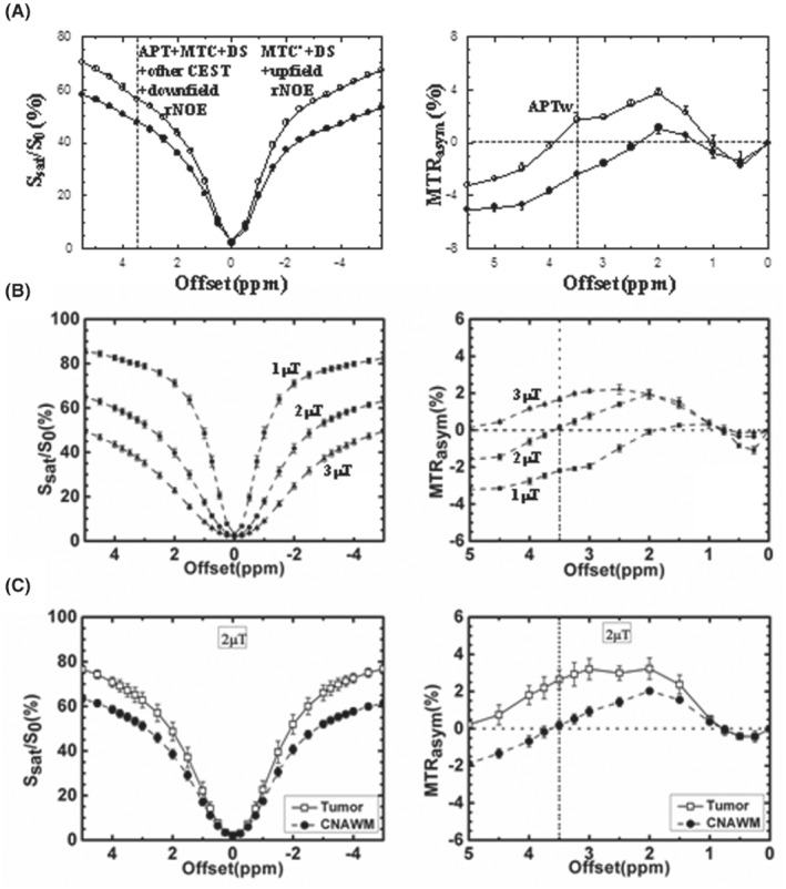
(A) Z‐spectra and MTRasym spectra measured from a 9 L rat brain tumor model at 4.7 T (12 days post‐implantation, n = 6, T sat = 4 s, B1 = 1.3 μT). Tumor: open circles; contralateral normal brain tissue: solid circles. The APT effect is visible as a small resonance at the offset of 3.5 ppm in the Z‐spectrum. The effect is stronger in the tumor than in the contralateral normal region. There is a small difference between the downfield and upfield semi‐solid MTC effects (namely, MTC vs. MTC′) in normal tissue, which is reduced in the tumor. Reproduced with permission and with some additions from Salhotra et al. 197 (B) Z‐spectra and MTRasym spectra of white matter from healthy subjects (n = 4), obtained at 3 T with 3 different RF saturation strengths and T sat = 500 ms. The error bars are too small to see clearly. White matter MTRasym(3.5 ppm) is roughly 0 at 2 μT. (C) Z‐spectra and MTRasym spectra measured from brain tumor patients at 3 T (n = 8, T sat = 500 ms, B1 = 2 μT). Tumor: open squares; contralateral normal‐appearing white matter (CNAWM): solid circles. The APTw signal is stronger in the tumor than in the CNAWM. (B) and (C) reproduced with permission from Zhao et al. 142
3. HISTORY OF THE MECHANISM AND THE EVOLUTION OF ITS UNDERSTANDING
Originally, APTw imaging was designed for in vivo imaging of mobile protein content in tumors and pH changes in tissue during ischemia (because of the strong dependence of the amide proton exchange rate on pH in the physiological range). 1 , 2 It exploits the concept that the CEST mechanism can detect changes in amide proton signals. These 2 applications are based on early spectroscopy studies that showed an increased amide proton signal in proton spectra during ischemia (because of slower exchange) 78 and very large amide proton signals in perfused tumor cells. 78 , 79 These hypotheses were confirmed in vivo where ischemia experiments in rats at 4.7 T showed a small decrease in MTRasym spectra over a chemical shift range of 2.5 to 5 ppm from the water, with the clearest decrease at 3.5 ppm, attributed to reduced pH. 1 The first in vivo studies in animal tumor models at the same field and RF settings showed a broad, increased MTRasym effect ranging from 1.5 to 5 ppm. 2 In that paper, the signal change over this range was attributed to backbone amide and other exchangeable protons, which are typically seen in this range in high‐resolution NMR protein studies and in the MR spectra of perfused cells and brain. Because of the results of MR spectroscopy, the authors focused on the 3.5 ppm offset.
In early work, 2 the increased APTw signal in tumors (relative to normal brain tissue) was attributed to (1) the increased mobile amide proton concentration in the tumor associated with the increased concentration of mobile cytosolic proteins and peptides because of higher cellularity, and (2) the slightly increased amide proton exchange rate because of marginally higher intracellular pH (<0.1 unit, as reported from phosphorus MR spectroscopy studies in patients) 80 , 81 , 82 in tumor cells. This has been confirmed in subsequent studies 83 , 84 , 85 , 86 and is consistent with increasing protein concentrations in tumors, as revealed by proteomics 87 , 88 and by in vivo MR spectroscopy. 89 It has been reported that solid tumors have an acidic extracellular pH and a neutral‐to‐alkaline intracellular pH. 90 , 91 Notably, reduced acidic extracellular pH in tumors would substantially reduce the amide exchange rate and, therefore, the contribution of extracellular proteins and peptides. The intracellular origin is supported by a recent study showing that there was no correlation between the amide proton exchange rate and extracellular pH. 92
Over the years, the understanding of the APTw contrast mechanism has evolved. Several other possible effects that may contribute to the APTw hyperintensity in tumors include: (3) reduced semi‐solid MTCasym (3.5 ppm) in tumors because their Z‐spectra are less asymmetric thanin white matter and gray matter. This effect becomes more visible when using a longer saturation time, with B1 increasing from 0.5 to 3 μT. 76 , 93 (4) Decreased aliphatic rNOEs of mobile macromolecules at and around the opposite frequency offset −3.5 ppm. 6 , 73 , 74 , 75 Based on Equation (3), the MTRasym‐based APTw image signal has multiple contributions (primarily including aliphatic rNOE and MTCasym). In the brain, (3.5 ppm) (≈ −rNOE − MTCasym) is negative and reduces the MTRasym (3.5 ppm). Therefore, this contribution is actually a synergistic factor that enhances the APTw image contrast of the tumor because of the reductions in aliphatic rNOE and MTCasym in tumors relative to brain tissue. 94 , 95 , 96 (5) Downfield rNOEs (e.g., in aromatic residues). This possible confounder at and around +3.5 ppm downfield of water has been previously explored in studies of protein solutions, tissue homogenates, and brains in vivo, and will partially counteract the aliphatic rNOE contribution. 97 , 98 (6) Spillover and MTC dilution effects. 67 When performing the MTRasym analysis, asymmetric effects relative to water are visualized, and symmetric background signals (water T2 [T2w]‐based spillover and the symmetric portion of MTC) are removed under the zeroth‐order approximation. However, the APT effect is always diluted by competing spillover and MTC effects, resulting in the fact that T2w and MTC alterations may influence the magnitude of APTw contrast. (7) Contamination by T1w changes 67 (but there is a nonlinear relationship between APTw and T1w). As shown in Equation (1), the APT effect scales with T1w. However, the effects of increased T1w (decreased R1w) and water content (denominator of fs) in brain tumors are canceled out partially. 84 Further, apart from the T1w recovery effect, there is an opposing T1w effect on APTw through dilution effects, as longer T1w leads to lower Z‐spectra, therefore, increasing the dilution effects, which lowers the APT effect. 99 These 2 effects cancel each other out to some extent, depending on experimental RF settings. Simulation studies have shown that APTw increases with T1w at lower B1, but is roughly insensitive to T1w or even decreases with T1w at higher B1. 99 , 100 In addition, the dependence of APTw MRI on T1w can be reduced using non‐steady‐state saturation. Fortunately, when RF strength is approximately equal to 2 μT (as recommended for brain tumor imaging at 3 T), APTw intensity has been found to be reasonably robust against the change in T1w. 99 , 100 Therefore, a correction for T1w changes is not necessary for APTw imaging of brain tumors at 2 μT on clinical 3 T scanners. Of course, this robustness still has limits. 101 , 102 Because the significant T1w effect of Gd contrast agents may bias APTw imaging, it is important to remember that the APTw acquisition should always be performed before the injection of contrast agents. 103 (8) CEST signals from exchangeable protons resonating nearby. At 3 T, most exchangeable protons of macromolecules and metabolites (such as amines and hydroxyls) are in the fast‐exchange regime (ksw » Δωs), and their resonances start to coalesce with water. Reduced extracellular pH in tumors may reduce the exchange rates of extracellular amines and other fast‐exchanging protons and make them become detectable. 104 It is worth noting that the linewidth of some nearby intermediate‐exchange resonances (including those from guanidinium protons at 2 ppm, which have an exchange rate of about 800‐1000 Hz 105 , 106 and, therefore, an effective linewidth of about 2.0‐2.5 ppm at 3 T) may be sufficiently large to be partially irradiated and detected at 3.5 ppm. 107 , 108 (9) APTw effect from mobile proteins in liquefactive necrosis. Proteinaceous fluid compartments in tumors, such as liquefactive necrosis, would result in large hyperintensity on APTw images 12 , 24 because of the abundance of proteins and protein fractions at higher mobility. In addition, plausible protein denaturation processes would generate such a signal increase. 109 , 110 Notably, reduced dilution effects in liquefactive necrosis would lead to an apparently high APTw contrast between this compartment and normal brain tissue. To simplify radiology readings, a new APTw metric based on the background MTR value has been proposed to suppress APTw signals of large liquefactive necrosis. 111 However, a further validation is needed for this APTw metric. (10) APTw effect from mobile proteins in blood vessels and hemorrhage. Blood has high concentrations of hemoglobin in erythrocytes and albumin in plasma, and a higher pH (∼0.2 pH units, relative to brain tissue), 112 which would contribute to the increased APTw in well‐perfused tumors because of induced angiogenesis. 37 , 113 In addition, like liquefactive necrosis, intratumoral hemorrhage would demonstrate large APTw hyperintensity, particularly at hyperacute and acute stages. 24 , 114 , 115
Given all these potential synergistic or competitive effects, the contributions of which are affected by experimental RF settings and analysis approaches, the question arises whether the chosen term “APT‐weighted” imaging is still justified, because it implies that the APT component is the major source of this signal. With the above list as a reference and amide protons as one important contributor, this naming is valid under the careful choice of acquisition and analysis. 94 , 95 , 96 For clinical APTw imaging of brain tumors, we would seek a pragmatic compromise that not only effectively detects APT, but also can be standardized so that all other effects are consistent between vendors and studies. Notably, recent radiographic‐histopathologic correlation studies 26 , 29 , 43 have clearly demonstrated that MTRasym(3.5 ppm) is a valid metric that adds clinical value to the imaging of brain tumors at 3 T. Further validation is still needed on different pathology types for the various recommended APTw approaches described below.
In light of the above list of possible confounding contributions, there is still a great need for continued work on CEST methods with increased signal specificity and/or parameter quantification, as such methods may ultimately have improved diagnostic use. Some of such pulse sequences and data analyses that attempt to separate APT effects from the other contributions in APTw imaging are discussed in Table 3 and “Data Processing” below. Additional methods that incorporate different (and sometimes radically different) acquisition protocols are reviewed elsewhere. 116 , 117 The current paper is focused solely on providing a reasonable standard for assessing brain tumors in daily clinical practice using a currently established MTRasym‐based APTw approach.
4. PULSE SEQUENCES
4.1. RF saturation approaches and parameters
Currently, no consensus‐based APTw MRI pulse sequences or parameters are available for clinical MRI systems between different vendors, even for the most studied application of brain tumors. As mentioned above, the APTw signal depends on the APTw pulse sequence features and parameters used. Notably, the APTw signal is affected by dilution effects, the contributions of which vary with the saturation amplitude and time. Because of this dependence, to achieve reproducible APTw imaging contrast for brain tumors, a consensus choice of certain saturation parameters is needed. Based on the abundant literature of the last decade, and taking into account saturation time limitations for amplifiers on some equipment, we recommend:
| (4) |
where T sat (during which saturation is applied and transfer occurs) may consist of different combinations of RF pulses and inter‐pulse delays, DCsat is the RF saturation duty cycle (DC), and B1rms is the root‐mean‐square B1 value of a saturation pulse train with duration tp and inter‐pulse delay td, defined as:
| (5) |
Notably, Equation (4) provides some flexibility that is needed at this stage. However, to enhance reproducibility and the comparison of results across vendors and sites, our preferred and more specific recommendation as a long‐term goal is:
| (6) |
The choice of these RF saturation parameters is based on the following rationales.
It has been shown that the APTw contrast in brain tumors (T1w ≈ 1.5‐1.6 s in the solid portion of gliomas at 3 T) 118 , 119 improves substantially (Figure 2A) when lengthening T sat from 0.5 s to 2 s. 120 For clinical APTw imaging, a CW block pulse of several seconds is possible for RF saturation with transmit‐receive head coils on a standard 3 T clinical system, 22 similar to typical animal APTw experiments. However, most standard 3 T clinical systems use body coils for transmit, which results in stricter limitations on RF amplifier DC (typically 50%), saturation pulse length, and, to some extent, SAR. In the past decade, this has been addressed by a few different methods (Tables 2 and 3), such as pulse‐train, time‐interleaved parallel RF transmission (pTX), or pulsed steady state APTw MRI. The pulse‐train pre‐saturation (a train of pulses separated by brief delays) has been used in some early pre‐clinical APTw studies 1 , 2 and in most 3 T clinical investigations. 121 , 122 , 123 , 124 , 125 , 126 , 127 , 128 The use of pulse trains can achieve a DCsat >90% and a T sat >0.8 s on most 3 T MRI scanners from different vendors, greatly alleviating the limitations in amplifier duty‐cycles and saturation pulse lengths. Notably, in a recent study on a brain tumor patient using different pulse‐train RF saturation modules, Herz et al 129 confirmed the decreased tumor APTw signal intensities with decreasing DCsat (Figure 2B). To truly maximize the saturation efficiency, Keupp et al 130 , 131 introduced a time‐multiplexed RF saturation method in pTX systems (Figure 3). By time‐interleaving 2 RF sources of the body coil (the quadrature channels), each with a 50% idle‐time, one can achieve an increased length of the pseudo‐CW saturation pulse train, completely meeting the needs of CEST/APTw imaging. Finally, the pulsed steady‐state CEST sequence, previously implemented on 1.5T 132 and 7 T 128 , 129 human MRI systems, 133 , 134 but similar to the 3 T MTC steady‐state sequence, 135 is currently being optimized for APTw MRI on 3 T clinical systems. 136 , 137 , 138 , 139 , 140 , 141 With this, the CEST effect is built up over multiple saturation pulses and each is followed by an imaging acquisition segment. However, the DC for such a pulsed steady‐state sequence is inherently low.
FIGURE 2.
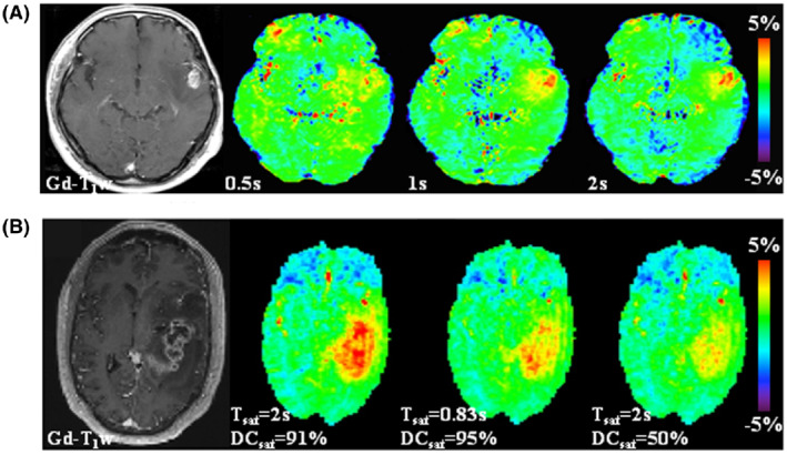
Illustration of the need for a saturation period (T sat) on the order of 1‐2 s and for a high RF saturation duty cycle (DCsat) for APTw MRI of brain tumors at 3 T. Gd‐enhanced T1w images are included with each example as a morphological reference. (A) An example of APTw MRI (B1rms = 2 μT, DCsat = 100%) for a patient with glioblastoma showing that the APTw signal in the relevant regions increases with T sat. Reproduced from Togao et al. 120 (B) APTw and Gd‐enhanced T1w images for a glioblastoma patient acquired with 3 different pulse‐train RF saturation modules (B1rms = 2 μT). The APTw hyperintensity can be seen clearly in the tumor region relative to normal‐appearing brain tissue, the highest for the module (T sat = 2 s, DCsat = 91%) and the lowest for the module (T sat = 2 s, DCsat = 50%). Reproduced from Herz et al. 129
FIGURE 3.
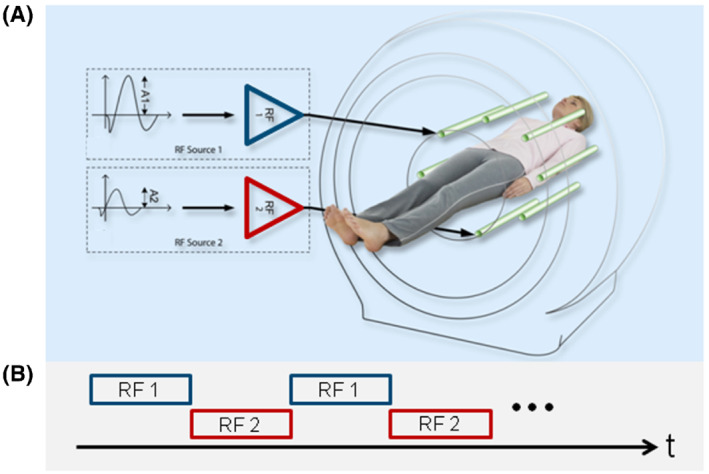
Schematic representation of parallel RF transmission (pTX, dual transmit here) (A), alternated over time (B), used for APTw MRI RF saturation. To achieve 100% duty‐cycle RF saturation, 2 independent sources, RF1 and RF2, are driven by the RF amplifiers in a time‐interleaved fashion, therefore, running each amplifier at 50% duty‐cycle and limited pulse duration according to the hardware specifications. Reproduced with permission from Keupp et al. 61 , 130
The amide proton pool, which has a k sw range of tens to hundreds of Hz in vivo, can be efficiently labeled using an RF saturation strength (B1 or B1rms) between 1 and 3 μT (1 μT = 42.567 Hz). Importantly, the use of 2 μT in MTRasym‐based APTw imaging of brain tumors provides some advantages. When a B1 of 2 μT is used, the APTw signal is almost 0 for normal brain tissue (Figure 4A), because of the presence of a negative (3.5 ppm) compensating the APTR. In addition, the APTw signal should always be negligible in the cerebrospinal fluid (CSF) because of the symmetry of the CSF Z‐spectrum. Therefore, using this B1 and sufficient T sat (0.8‐2 s), the APTw images are zeroed in most normal brain areas, the ventricles and, in patients, the resection cavity (Figure 4B). This convenient background allows easy detection of hyperintense APTw signals in high‐grade tumors or hypointense APTw signals in ischemic tissue, which is convenient for clinical assessment. 142
FIGURE 4.
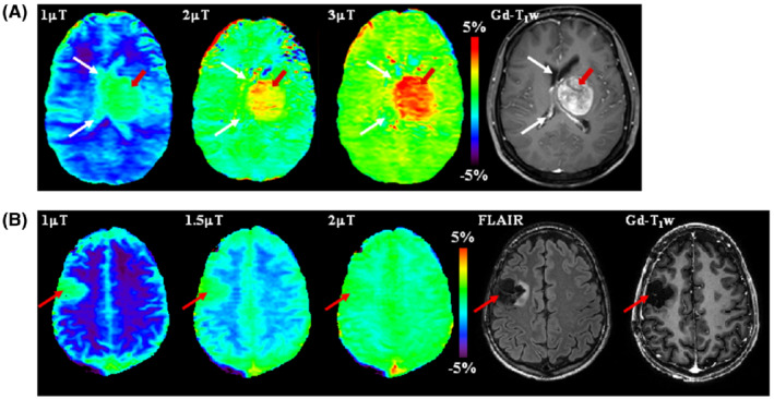
APTw images at 3 T acquired at different RF saturation strengths. (A) A patient with cerebral metastasis. The tumor (red arrows) shows hyperintense signal on all APTw images. However, the lesion margins are poorly delineated on the APTw image at 1 μT because of the presence of cerebrospinal fluid (CSF) artifacts (white arrows). Reproduced with permission from Zhao et al. 142 (B) A glioma patient post‐treatment. The APTw signals at different B1 strengths are all around 0 in the resection cavity (as in CSF), but very different in normal brain tissue (Figure 1B). Therefore, at 1 μT, the resection cavity (red arrow) shows unexpected apparent APTw hyperintensity. However, the APTw image at 2 μT is homogenous for most brain regions, including the resection cavity (red arrow). Notice the residual hyperintensity in the sagittal sinus likely because of the high protein content of blood. Unpublished data from Dr. Hye‐Young Heo. The study was approved by the local Institutional Review Board
Four RF saturation types (types [a]‐[d]) recommended for brain tumor APTw imaging on 3 T clinical MRI scanners are given in Table 4, in which types (a) and (b) are the 2 preferred options. For all pulse‐train saturation types, we recommend B1rms = 2 μT, T sat = 0.8‐2 s, and DCsat ≥ 50%. This recommendation retains some flexibility for the parameters of shaped pulses (such as shape, length, and phase). Type (a) and several examples using type (b) are further compared in Figure 5A and B1‐B3. Type (a) is the ideal approach and is allowed only with transmit‐receive head coils, some state‐of‐the‐art RF amplifiers, or single‐slice APTw imaging protocols. Fortunately, the pulse‐train methods in type (b) can be realized with the RF amplifier hardware configuration from all different manufacturers. Time‐interleaved pTX is one good option, but not a requirement, because some state‐of‐the‐art RF amplifiers can support a DCsat >90% for body coils at the recommended B1 strength for APTw MRI. The data in Figure 6 confirm that the pulse‐train methods in type (b) can provide fairly similar Z‐spectra, MTRasym spectra, and APTw images in healthy volunteers from three 3 T MRI scanners of different vendors. When preferred types (a) and (b) are not feasible, we recommend using types (c) or (d). A good example for type (c) is shown in Figure 5C, which has been widely used in brain tumor studies previously. 25 , 30 A comparison of types (b)‐(d) can also be found in Figure 2B. To allow maximal reproducibility, several of the pre‐saturation schemes were recently shared in the open‐source pulseq‐CEST format 143 (see more details in the caption of Figure 5).
TABLE 4.
Recommendations for APTw imaging of brain tumors at 3 T
| Pulse sequences |
|---|
|
RF saturation approaches and parameters:
Lipid suppression:
Readout (including recovery time):
|
| Acquisition protocols |
|
| Data processing methods |
|
FIGURE 5.
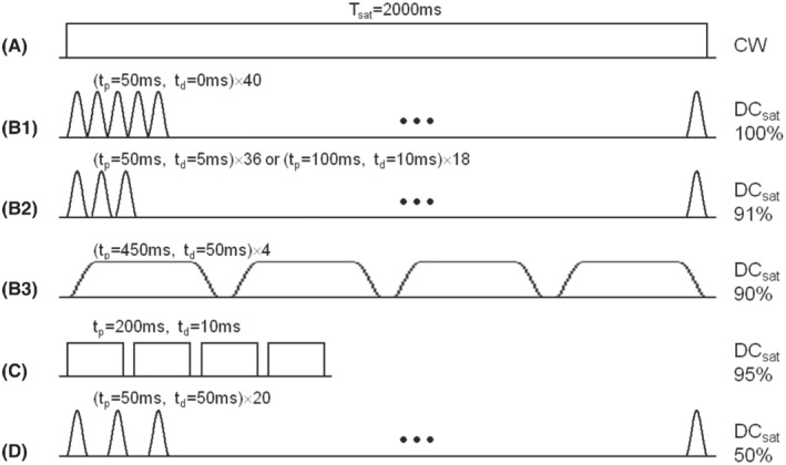
Recommended RF saturation methods for APTw imaging of brain tumors on 3 T clinical MRI scanners. (A) CW RF saturation (T sat = 2 s, B1 = 2 μT). (B1‐B3) Three pulse‐train RF saturation examples (T sat = 2 s, B1rms = 2 μT) with high DCsat (≥90%), respectively, proposed to be used initially on the Philips system by Keupp et al, 130 on the Siemens system by Zhang et al, 149 and on the GE system by Su et al. 198 Note that (B1) is typically achieved with the time‐interleaved pTX technique. Single‐lobe sinc‐Gaussian or any other saturation pulses may be used in (B1) and (B2), and Fermi pulses in (B3). (C) Shorter pulse‐train RF saturation (T sat = 830 ms, B1rms = 2 μT) with high DCsat = 95%, which was proposed by Zhu et al. 122 (D) Pulse‐train RF saturation (T sat = 2 s, B1rms = 2 μT) with standard DCsat = 50%. Single‐lobe sinc‐Gaussian saturation pulses are used as an example. (C) and (D) are not optimal, but have often been used previously. To exactly reproduce these pre‐saturation blocks, find their definition in the pulseq‐CEST library (A: APTw_000, B2: APTw_001, C: APTw_003, D: APTw_002) 143
FIGURE 6.
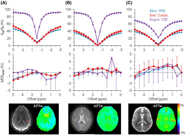
Preliminary results of Z‐spectra, MTRasym spectra, and APTw images acquired from adult healthy volunteers on a GE 3 T MRI scanner (Discovery MR750) (A), a Philips 3 T MRI scanner (Ingenia) (B), and a Siemens 3 T MRI scanner (Prisma) (C), using the recommended RF saturation methods (Figure 5B3, B1, and B2), respectively. Comparable regions of interest were chosen in white matter (blue lines), cortex (red lines), and cerebrospinal fluid (CSF, purple lines). A single‐slice TSE/EPI acquisition was used in (A) and (B), respectively, and the 3D snapshot GRE (7 s per offset) in (C). Similar Z‐spectra, MTRasym spectra, and APTw images were obtained for the 3 different vendors, particularly for white matter and cortex. Z‐spectra and MTRasym spectra of CSF show relatively larger standard deviations, which can be attributable to flow‐related effects. The use of the fast 3D snapshot GRE in (C) is associated with the larger partial volume effect in the second phase‐encoding (head‐foot) direction (CSF Z‐spectrum) and hyperintense vessel signals (APTw image). Standard deviations are ROI‐based (over the number of voxels), and therefore, dominated by the ROI tissue‐based spatial inhomogeneity, and provide only coarse insight in the image CNR. Some B0 centering errors are visible in some of the CSF curves, leading to larger standard deviation close to the water frequency. Unpublished data from Drs. Phillip Zhe Sun and Yin Wu (GE System), Dr. Jinyuan Zhou (Philips System), and Dr. Moritz Zaiss (Siemens System). Studies were approved by the respective local Institutional Review Boards
4.2. Lipid suppression
Because APTw images are based on the MTRasym analysis of saturation images at ±3.5 ppm from water, lipid artifacts may occur because of the unequal lipid suppression by the saturation pulse at frequencies above and below the water. In addition, when an EPI‐type fast imaging readout is used, large lipid ghosting artifacts may interfere with APTw imaging. 144 It should be noted that the issue of fat suppression in the brain is much less severe than in body applications of APT, where partially fat‐containing voxels require sophisticated methods to remove fat signals. Normal brain tissue and brain tumors do not contain MR‐visible fat components (with the rare exception of teratoma), so lipid artifacts mostly arise from fat outside the brain (skull). Sun et al 144 showed that a spin‐echo sequence with a water‐based, chemical‐shift‐selective refocusing pulse could avoid such a lipid artifact in MTRasym images. Zhu et al 122 demonstrated that lipid suppression can be effectively achieved using chemical‐shift selective removal before acquisition with an asymmetric, frequency‐modulated, lipid suppression pulse, followed by a crusher gradient. Several methods have been proposed to suppress strong lipid artifacts in breast CEST imaging. 145 , 146 , 147 Fortunately, it has been shown that the standard spectral pre‐saturation inversion‐recovery (SPIR) method is generally sufficient for lipid artifact removal in APTw imaging of the brain. 148 , 149
4.3. Readout
Clinical application of the APTw MRI approach will be more feasible if fast volumetric imaging acquisition (<5 min) can be achieved. Both multi‐slice and 3D approaches have been used in CEST/APTw imaging. In multi‐slice acquisitions, there generally are CEST signal losses because of T1w relaxation differences based on the order in which the slices are acquired, so corrections may be needed. 150 However, in a 3D acquisition with centric encoding, each line of k‐space contributes equally to all reconstructed slices, and differences in saturation caused by differences in T1w relaxation between slices can be minimized. 122 Therefore, 3D acquisition is preferred for volumetric APTw imaging. For instance, Zhu et al 122 developed a 3D APTw MRI technology that allows fast acquisition on 3 T clinical instruments, using 4 elements of 200 ms with 10 ms space in between (DCsat = 95%) for gradient‐ and spin‐echo (GRASE) imaging with adiabatic lipid suppression pulses. This sequence has been applied successfully to clinical studies at many sites. 30 , 151
Volumetric APTw MRI currently requires a scan time of 3 to 10 min, because of the use of multiple RF saturation frequencies (to correct for the B0 inhomogeneity) and multiple acquisitions (to increase the SNR). Various acceleration approaches and fast imaging acquisition techniques have been used to accelerate CEST/APTw imaging (Figure 7), including SENSE, 152 , 153 GRAPPA, 154 controlled aliasing in parallel imaging results in higher acceleration (CAIPIRINHA), 155 GRASE readout, 122 turbo‐spin‐echo (TSE) readout 22 , 23 , 156 (including sampling perfection with application‐optimized contrasts by using different flip angle evolutions [SPACE]), 149 and a gradient‐echo (GRE)‐based snapshot approach. 157 , 158 , 159 The combination of 3D TSE readout with time‐interleaved pTX saturation provides a fast and more sensitive 3D APTw imaging sequence (Figure 7A), which was the method used in the first commercial APTw imaging sequence on Philips 3 T MRI scanners. 60 , 61 In addition, several novel undersampling acquisition and reconstruction approaches (including keyhole, spectroscopy with linear algebraic modeling, compressed sensing, and deep learning) 160 , 161 , 162 , 163 , 164 , 165 have been used successfully to accelerate CEST/APTw acquisitions. The reconstruction‐oriented, reduced k‐space acquisition requires more advanced data processing, but this can all be automated on the scanners (including compressed sensing‐based image reconstruction and B0 inhomogeneity correction) 60 , 61 to streamline the clinical workflow.
FIGURE 7.
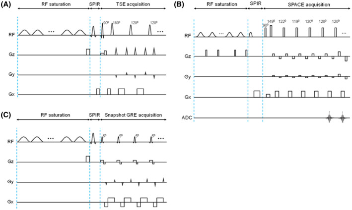
3D APTw imaging sequence diagrams, all consisting of a pulse‐train RF saturation module, a SPIR lipid suppression pulse, and 3D image readout. (A) An example used in the Philips 3 T clinical MRI system. The time‐interleaved pTX‐based RF saturation module consists of 40 single‐lobe sinc‐Gaussian saturation pulses (50 ms each, T sat = 2 s, B1rms = 2 μT, DCsat = 100%), corresponding to Figure 5B1. The TSE readout module contains selective excitation and selective/non‐selective refocusing pulses (120°). (A) Made according to Keupp et al. 130 , 131 , 170 (B) An example used in a Siemens 3 T clinical MRI scanner. The RF saturation module consists of a train of 100‐ms‐long Gaussian pulses with a 10‐ms gap in between (DCsat = 91%), corresponding to Figure 5B2, and a 5‐ms‐long, 15‐mT/m‐strong crusher gradient is applied during the gap period. The SPACE readout module contains non‐selective excitation and refocusing pulses. The refocusing part has 4 startup pulses with flip angles of 149°, 122°, 119°, and 120°, and then executes constant 120° pulses. (B) Reproduced with permission from Zhang et al. 149 (C) An example of the snapshot GRE CEST used in a Siemens 3 T clinical MRI scanner. The RF saturation module consists of a train of 36 50‐ms‐long Gaussian pulses with a 5‐ms gap in between (DCsat = 91%), corresponding to Figure 5B2, and a 2‐ms‐long, 15‐mT/m‐strong crusher gradient is applied after the preparation period. The snapshot GRE readout module contains slab‐selective, low flip‐angle excitation pulses of 5°‐7°. (C) Made according to Zaiss et al 157 and Herz et al. 129
Based on previous studies, a fast 3D acquisition technique (in‐plane resolution 1.8‐2.2 mm; through‐plane resolution 3‐6 mm), integrated with a feasible, optimized RF saturation scheme and an effective lipid suppression method, and is recommended for brain tumor APTw imaging on 3 T clinical MRI scanners (Table 4). T rec or TR is generally limited by the SAR, and we suggest using T rec ≈ 2T1w (tumor T1w ≈ 1.5‐1.6 s at 3 T). 118 , 119 GRASE, 122 TSE, 61 SPACE, 149 and GRE 157 , 158 , 159 have widely been used in previous studies of brain tumor APTw imaging and are among the candidate readout sequences. However, we recommend retaining some flexibility for the 3D readout module, currently, because the choice of this pulse sequence component does not affect the APTw contrast per se.
5. ACQUISITION PROTOCOLS
The minimum data required to calculate MTRasym is related to a 2‐offset (±3.5 ppm) APTw imaging protocol. However, MTRasym analysis is complicated by B0 frequency inhomogeneity and scanner instability, which causes spatio‐temporal resonance frequency variations. The 2‐offset protocol is highly susceptible to B0 variations between voxels, which can be problematic near air‐tissue interfaces, even with up to 2nd‐order shimming. 122 Two kinds of APT imaging acquisition protocols have been reported in the literature that address this issue (Tables 2 and 3): acquiring a full Z‐spectrum consisting of downfield and upfield frequency offsets from the water resonance, or acquiring limited frequency offsets at and around ±3.5 ppm, plus a ΔB0 map for frequency offset referencing. A full Z‐spectrum is often acquired for research purposes and allows for correction of B0 variations because it includes samples near water and amide resonances. The APTw signal is known to appear at the offset of 3.5 ppm; therefore, only limited offsets at and around ±3.5 ppm need to be acquired. 12 To have the possibility to correct for B0 differences on a voxel‐by‐voxel basis, it is necessary to acquire multiple offsets at and around ±3.5 ppm. The ΔB0 map is often obtained using an extra, more time‐efficient scan, such as the widely used water saturation shift referencing (WASSR) 166 or GRE phase‐based methods. 156 , 167 According to the literature, 122 the B0 inhomogeneity in the brain is typically less than 20 Hz and up to 100 Hz near air‐tissue interfaces (ears, sinuses) at 3 T. With a ΔB0 map available, it has been shown that a 6‐offset APTw imaging protocol (±3, ±3.5, and ±4 ppm) with 2‐to‐4 acquisitions at ±3.5 ppm (Figure 8A), can provide B0 inhomogeneity‐corrected APTw images of sufficient SNR. 23 This minimal Z‐spectrum data acquisition allows 3D full brain imaging within clinically acceptable acquisition times (e.g., <5 min). More acquisitions at ±3.5 ppm can be used to increase the SNR. Of course, a relatively larger offset interval (e.g., ±2.75, ±3.5, ±4.25 ppm) or extra offsets (e.g., ±2.5, ±3, ±3.5, ±4, ±4.5 ppm) may be used when large B0 inhomogeneities exist. 23 , 168 The tradeoffs for these are larger data interpolation errors (see next section) and more scan time, respectively.
FIGURE 8.
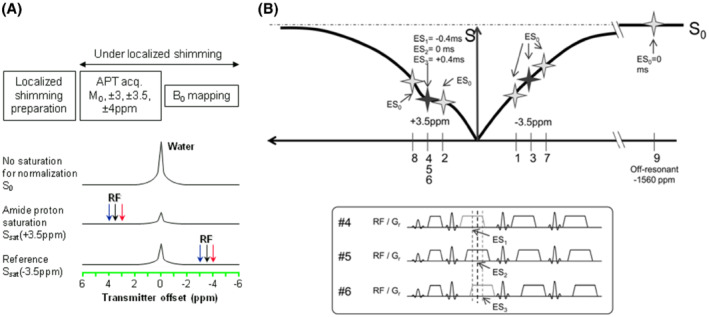
(A) A commonly used 6‐offset APTw protocol. During the preparation, localized shimming is performed. The optimal shim parameters and scanner's center frequency are determined and applied to the subsequent APTw data acquisition and ΔB0 mapping scans. During the APTw data acquisition, extra offsets (±3, ±4 ppm) are acquired to correct for spatial and temporal B0 inhomogeneities. Reproduced with permission from Zhou et al. 23 (B) An APT‐Dixon method. The imaging is performed at frequency offsets ±3.1, ±3.5, ±3.9, and −1560 ppm (S 0). Image acquisition is repeated 3 times at +3.5 ppm. Acquisition windows and readout gradients are shifted (echo‐shift, [ES]) by +0.4 ms (ES1), 0 ms (ES2), and −0.4 ms (ES3) in each acquisition at +3.5 ppm for Dixon‐type ΔB0 mapping. Reproduced with permission from Togao et al. 170
Recently, a number of novel methods have been proposed to correct B0/B1 field inhomogeneity or frequency drift in clinical CEST/APTw imaging at both 3 T and 7 T. 169 , 170 , 171 , 172 , 173 , 174 , 175 , 176 , 177 , 178 Keupp et al 169 , 170 developed a so‐called CEST‐Dixon method at 3 T that can map the intrinsic B0 inhomogeneity using echo shifts during the APTw acquisition (Figure 8B), concluding that this self‐corrected method is more robust than separate B0 mapping approaches. Schuenke et al 171 proposed the water shift and B1 (WASABI) method that can yield simultaneous B0 and B1 mapping within about 2 min at 3 T and 7 T. The B1 variations in the brain at 3 T are typically within ±10% and can be up to ±30% in some regions, such as in the infratentorial region and at the superior part of the brain. 159 Theoretically, B1 inhomogeneity affects APTw signal when different brain regions experience varying amounts of saturation. For example, the saturation efficiency α in Equation (1) is a function of B1, and spillover/MTC dilution effects change with B1. 67 At 3 T, when a body coil is used, these effects taken together may not be sufficient to substantially affect APTw contrast within most brain slices (Figure 6). However, this may be an issue only in the infratentorial and superior brain regions, and further assessments are needed. Technically, if available, parallel transmit and B1 shimming, as well as B1 inhomogeneity corrections during processing (from B1 mapping), should be used to reduce the possible issue. Poblador Rodriguez et al 177 recently compared several static and dynamic ΔB0 mapping methods for correcting CEST MRI in the presence of temporal B0 field variations at 7 T. The results indicated that, in the presence of frequency drift, the 3 dynamic methods (which integrate ΔB0 mapping into the CEST measurement) had significantly improved ΔB0‐correction performance over established static methods. Self‐corrected CEST‐GRE‐2TE (using phase data directly generated by double‐echo GRE readout), comparable to CEST‐Dixon, was the most accurate and straightforward sequence to implement.
The APTw acquisition protocol currently recommended for brain tumors on 3 T clinical MRI scanners is listed in Table 4. We recommend the acquisition of at least 6 offsets and an unsaturated image (S 0, ±3, ±3.5, ±4 ppm, or S 0, ±3.1, ±3.5, ±3.9 ppm), in combination with B0 shimming (2nd order preferred) and a B0 shift reference. Further offsets can be applied, if a larger B0 inhomogeneity is expected. Because the APTw effect in vivo is often small (2‐4% of the water intensity in tumor), multiple acquisitions are often needed to increase the APTw SNR. We recommend that S sat(±3.5 ppm) images should have an SNR of at least ∼50, corresponding to 2‐to‐3 acquisitions for the TSE readout, with an in‐plane spatial resolution of about 1.8 to 2.2 mm and a through‐plane resolution of 3 to 6 mm. Notably, S0 without RF saturation should be acquired using the same TR as saturated images. It is acceptable that a saturated image at a very large offset is used as S0, which avoids potential drift effects with RF power changes. In this case, ±300 ppm or further from water should be chosen. At least 1 dummy scan or shot is required for the single‐shot or multi‐shot acquisition, respectively. Finally, an intrinsically/dynamically referenced ΔB0‐correction method (such as CEST‐Dixon or CEST‐GRE‐2TE) 128 , 129 , 177 is a good option to correct for B0 variations, but a separate ΔB0 mapping approach is generally acceptable at 3 T. For the latter, it is, of course, important to run the ΔB0 mapping and APTw scans under the same shimming and ideally in immediate succession, because of potential B0 drift effects (Figure 8A). The approaches and parameters suggested in Table 4 allow for the greatest degree of flexibility in the application of APTw imaging to multi‐center clinical trials for the assessment of brain tumors and novel therapies.
6. DATA PROCESSING
Different data processing approaches have been proposed to quantify the APT effect in vivo. Examples are the widely used MTRasym analysis, 179 the 3‐offset method, 75 and the extrapolated semi‐solid magnetization transfer reference (EMR) method, 95 , 96 which were designed to, as much as possible, remove the DS and MTC background signals based on a reference signal. Other approaches include various model‐based, Z‐spectral fitting approaches, such as multi‐pool Lorentzian fitting 180 , 181 , 182 or multi‐pool Bloch‐McConnell equation fitting. 183 , 184 These often allow a more specific CEST quantification and provide the ability to quantify multiple CEST parameters. The most suitable APT analysis method may depend on the setting of RF saturation amplitudes. At relatively low saturation amplitudes (<1 μT), APT and rNOE peaks are often distinguishable and relatively easy to fit. However, at 2 μT recommended for brain tumor imaging at 3 T, the distinct APT signal at 3.5 ppm is often invisible (because of a large saturation bandwidth on the order of ppm) 94 and the model‐based fitting approaches, designed to separate out more pure APT effects, may not work well. Recently, a quasi‐steady‐state (QUASS) CEST analysis method was developed to account for the effects of finite saturation time and relaxation delay, which may facilitate more robust CEST quantification of individual resonances. 185 , 186 Here, we focus on the consensus on APTw imaging using MTRasym analysis, whereas other quantification approaches will require a separate evaluation and consensus.
Notably, in addition to its simplicity and speed, MTRasym‐based APTw imaging at 2 μT has some other useful characteristics that are not directly related to amide proton exchange properties, such as the close‐to‐0 APTw signal in healthy tissue and the coarse T1w independence, as discussed above. According to Table 2, when a B1rms of 2 μT and a T sat of 2 s are used on 3 T MRI scanners, very similar APTw intensities or contrasts can be observed from different vendors/sites (grade‐4/3/2 glioma APTw contrast = 4.0%/2.2%/1.0% on GE; grade‐4/3/2 glioma APTw signal = 4.1%/3.2%/2.1% on Philips; high‐grade glioma APTw signal =3.5% on Philips), 54 , 26 , 164 ranging approximately from 1% to 4% in solid tumors of different grades. The MTRasym(3.5 ppm) or APTw metric has, therefore, become the basis of the first commercial APTw imaging sequence on 3 T clinical MRI scanners. 60
Based on previous studies, we recommend MTRasym (3.5 ppm, B1rms = 2 μT, T sat >0.8 s, DCsat ≥50%) for brain tumor APTw imaging on 3 T clinical MRI scanners (Table 4). Using the recommended 6‐offset acquisition protocol and estimate of B0 offset, the equivalent value for the signal at ±3.5 ppm should be calculated using interpolation (linear or Lagrange interpolation being suitable with the small number of sample points) and MTRasym(3.5 ppm) calculated from these values. 26 , 148 , 151 Most APTw images have been displayed historically using a rainbow color scale. When the recommended B1 and saturation time values are used, this often leads to a green background in normal brain regions with positive, yellow/orange/red hyperintensities in high‐grade tumors (Figure 9) and negative, blue hypointensities in ischemic tissue. 142 We, therefore, recommend that the results should be displayed on MRI scanner consoles in a window of ±5%, with a specific rainbow colorbar (no. 013), defined by Interactive Data Language (IDL; Harris Geospatial Solutions, Broomfield, CO), 187 , 188 to visually cover all possible APTw signal changes seen in different clinical applications, and that both rainbow color and gray‐scale images are stored. In addition, to enable comparison of APTw images to previous published data, we suggest that the results should be displayed in publications using this colorbar and window. Nevertheless, we understand that radiologists may choose windows and levels themselves in reading rooms using different post‐processing solutions and may use gray‐scale or any color scales that they prefer for their specific clinical study with APTw imaging. Although radiologists usually prefer the rainbow scale, it is important to point out that it is increasingly recognized that this scale is not very suitable for color‐blind people and that the sharp color transitions may be misleading. 189 We encourage experimentation with the use of perceptually uniform sequential colorbars for APTw imaging in the future. Because of a lack of published data with such scales, we can currently not make a consensus recommendation about this.
FIGURE 9.
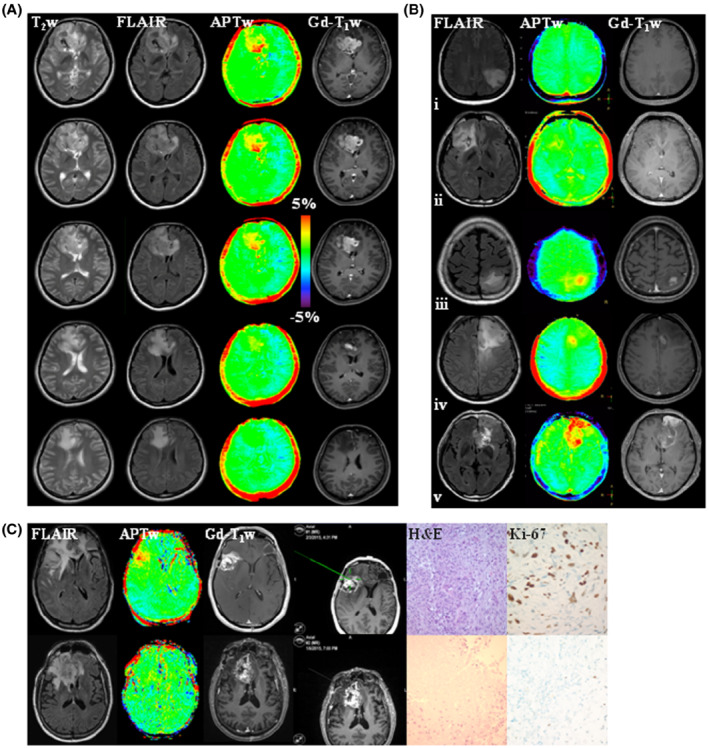
(A) An example of anatomic and APTw MR images for a patient with glioblastoma, isocitrate dehydrogenase (IDH) wild‐type. APTw images show hyperintensity in the Gd‐enhancing area, compared to the contralateral brain area. Five of 10 slices are shown. Unpublished data provided by Dr. Osamu Togao. The study was approved by the local institutional review board. (B) Five examples of anatomic and APTw MR images for patients with astrocytoma, IDH‐mutant, grade 2 (row i); oligodendroglioma, IDH‐mutant, 1p/19q codeletion, grade 2 (row ii); astrocytoma, IDH‐mutant, grade 3 (row iii); astrocytoma, IDH‐mutant, grade 4 (row iv); and glioblastoma, IDH‐wildtype, grade 4 (row v). Grade 3 or 4 gliomas typically show Gd enhancement and intermediate to high APTw hyperintensity. The 2021 World Health Organization classification of brain tumors was used. Unpublished data provided by Dr. Ji Eun Park. The study was approved by the local institutional review board. The recommended RF saturation method (Figure 5B1), 3D TSE readout, and APT‐Dixon method (Figure 8B) were used in (A) and (B). (C) Two examples of anatomic and APTw MR images, biopsied sites, and histology images from an APTw image‐guided stereotactic biopsy study, using the RF saturation method in Figure 5C, a 3D GRASE readout, and the 6‐offset APTw acquisition protocol from Figure 8A. (Top) A gliosarcoma patient with tumor recurrence, showing heterogeneous substantial APTw hyperintensity in the Gd‐enhancing area. The biopsied site marked by a screenshot had a high APTw signal (3.42%). (Bottom) A glioblastoma patient with treatment effect, showing homogeneous isointensity to minimal APTw hyperintensity in the gadolinium‐enhancing area. The biopsied site had a relatively low APTw signal (0.87%). Reproduced with permission from Jiang et al. 43
7. DATA INTERPRETATION
As is typical for all MRI approaches, there can be false‐positive and false‐negative findings because of low SNR. This certainly applies to CEST MRI, including APTw imaging, which detects changes in the range of a few percent of the water MRI signal. Consequently, the APTw MRI approach, based on difference images, is susceptible to motion and B0 shifts that may cause artifacts in the APTw images. Although low SNR, together with motion, can average out small hypo‐ or hyperintensities, strong motion artifacts can also lead to false hyper‐ or hypo‐intensities, as previously shown for dynamic CEST studies. 190 It has been reported on clinical scanners, with a saturation time of 2 s and a B1 amplitude of 2 μT, that the repeatability of the APTw signal was excellent in supratentorial locations, but it was poor in infratentorial locations because of severe B0 inhomogeneity and susceptibility that affect the APTw signal. 163 , 164 In addition, as discussed in “Acquisition Protocols,” the B1 inhomogeneity can be up to ±30% in the infratentorial and superior regions of the brain, which may affect the APTw signal. Therefore, interpretation of APTw imaging must include possible SNR, B0/B1 inhomogeneity, and motion influences, or rule these out at the acquisition or post‐processing stage, which may be possible with future developments.
Although APTw imaging is useful for brain tumor evaluation, there are pitfalls for APTw image interpretation. In addition to artifacts because of motion and B0 alterations, areas of large liquefactive necrosis, hemorrhage, or large vessels typically demonstrate high APTw signals and should not be mistaken as viable tumor. 11 Figure 10 gives several representative images of liquefactive necrosis and hemorrhage at different stages. Careful interpretation is needed with post‐operative‐stage tumors with the surgical cavity filled with proteinaceous fluid, unless a fluid suppression method is used (Figure 10C and D). 56 , 111 To distinguish between viable tumor and proteinaceous fluid, APTw images should generally be interpreted together with anatomic MRI (such as T2w, fluid‐attenuated inversion recovery (FLAIR), and pre‐ and post‐contrast T1w), SWI, diffusion, and perfusion (including dynamic susceptibility contrast‐enhanced and dynamic contrast‐enhanced) MRI sequences that are acquired during routine clinical tumor protocols. This comparison helps, on one hand, to recognize and assign non‐tumorous signals and potential artifacts on APTw images and, on the other hand, to identify tumor viability characteristics, which are not captured by the structural and perfusion‐weighted MRI (Figure 10D). The information provided by APTw MRI should be regarded as complementary to existing approaches, further extending the repertoire of diagnostic tools in radiology. Finally, and importantly, the selection of the color scheme in the APTw images can affect the interpretability of the information contained, as discussed in “Data Processing.” Advanced post‐processing solutions suited for APTw imaging can offer different color scales and windows, including perfusion‐like color ranges, which may be more familiar to the radiologist and, therefore, more easily readable (Figure 10D).
FIGURE 10.
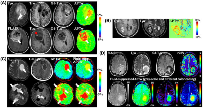
(A) Anatomic and APTw MR images for 2 patients with glioblastoma. (Top) An area of liquefactive necrosis (white arrow) is evident on standard anatomic MRI sequences. The APTw image shows that both the Gd‐enhancing tumor core and the proteinaceous fluid‐filled cavity (white arrow) have high APTw signal intensities. (Bottom) There is a large cavity filled with liquefactive necrosis (high FLAIR; white arrow) inside the tumor mass. T1w image demonstrates a small region of high signal intensities (red arrowhead) that is characteristic of hemorrhage. Both the tumor core and the liquefactive necrosis generally have high APTw signals, whereas the clot (red arrowhead) has a low APTw signal. Reproduced with permission from Wen et al. 24 (B) MRI of hemorrhage metastasis. At the periphery, the lesion shows isointensity on the T1w image and hypointensity on the T2w image, both consistent with acute hemorrhage. However, the central portion of the lesion shows hyperintensity on both T1w and T2w images, consistent with late subacute hemorrhage. The APTw image demonstrates a higher signal in the acute hemorrhage region than in the subacute hemorrhage region. Reproduced with permission from Jeong et al. 114 (C) Standard APTw and fluid‐suppressed APTw MR images for 2 patients with glioblastoma. (Top) A tumor with large central fluid content showing only thin rim enhancement after fluid suppression. (Bottom) A complex case with the significant cleanup of fluid APTw signals with fluid suppression. Reproduced with permission from Keupp and Togao. 111 (D) Anatomic, dynamic susceptibility contrast‐enhanced perfusion‐weighted, and fluid‐suppressed APTw MR images in a patient with a histologically confirmed astrocytoma, IDH‐mutant, grade 4. The anatomic images demonstrate a heterogeneous lesion with a rather solid central and well‐enhancing part (black arrows), a peripheral compartment (arrowheads), and some T2w/FLAIR mismatch without overt enhancement. The area of strong enhancement also demonstrates strong neo‐vascularization as is evident on the leakage‐corrected relative cerebral blood volume (rCBV) map (orange arrow), whereas the peripheral lesion shows a very low vascularization index. The APTw images in different color‐coding show significantly elevated signal in the enhancing tumor, suggesting clearly high‐grade features. Interestingly, the anterior rim zone, along with a halo surrounding the enhancing area, demonstrates mildly elevated APTw signal (arrowheads) that indicates likely high‐grade tumor characteristics, which are not captured by the perfusion‐weighted MRI. The APTw image appears to provide a more accurate functional tumor mapping than the rCBV map in this case. Unpublished data provided by Drs. Sotirios Bisdas and Laura Mancini (University College London Hospitals NHS Foundation Trust and UCL Queen Square Institute of Neurology) from an ongoing study approved by the Institutional Review Board and the local ethics committee. The data were acquired on a Siemens 3 T Prisma scanner, using a 3D APTw protocol (DCsat = 91%, B1rms = 2 μT, T sat = 2 s) and water shift and B1 for B0 and B1 mapping. Perfusion, water shift and B1, and APTw data were processed in Olea Sphere 3.0 software (Olea Medical, La Ciotat, France)
As discussed in “Pulse Sequences,” a correction for T1w changes is not necessary for APTw imaging of brain tumors at 2 μT on clinical 3 T scanners. T1w values decrease after Gd injection, especially in Gd‐enhancing regions that are of importance for tumor assessment. The Gd may remain there for a longer time, whereas it may clear faster from other tumor regions, leading to T1 heterogeneity in the tissue. Shorter T1w causes a reduced signal buildup in saturation transfer that leads to the region‐dependence of quantification because of T1w heterogeneity. 103 This could be corrected for if T1w could be known; however, because of the change in T1w over time with Gd concentration in the region, T1w mapping after Gd is actually difficult. We, therefore, do not recommend APTw MRI after Gd, but if it is acquired, we suggest adding a note for this to help the interpretation. 101 , 102 Other metrics with relaxation compensation ability have been suggested, 101 , 102 and a test to compensate for Gd‐induced T1 changes on injection was performed in an animal tumor model. 191 However, how these findings translate from animals to humans and from the sole amide CEST signal used to MTRasym is not yet clear. It is, therefore, not part of this guidelines paper.
8. CONCLUSIONS AND REMARKS
This paper reviews and recommends the currently optimized APTw approaches at 3 T with an attempt to standardize this imaging technology in the clinical setting, and focus on APTw imaging applications to brain tumors (Tables 4 and 5). When the preferred pulse‐train method (B1rms = 2 μT, T sat = 2 s) is applied to healthy volunteers, comparable Z‐spectra and MTRasym spectra can be obtained from the 3 T MRI scanners of the 3 main manufacturers. In addition, when using the recommended saturation sequences, currently published data from patients with brain tumors show that very similar APTw intensities or contrasts are observed for data from different vendors. We expect that these recommendations will become the first guidelines for APTw imaging of brain tumors on 3 T MRI systems from different vendors. When implemented, more medical centers will be able to use the same or comparable techniques in investigating the added clinical value of APTw MRI in larger independent patient cohorts and ultimately lead to biomarker status of this contrast for brain tumors. Reducing variability across vendors, sites, patients, and time will improve value and practicality of APTw imaging as a quantitative imaging biomarker that is consistent with the mission of the quantitative imaging biomarkers alliance (QIBA). 192
TABLE 5.
Tips for using APTw imaging in the clinical setting
| 1 | Check APTw imaging sequence parameters and test them with a healthy subject on sequence installation, after any scanner upgrade, and on a regular basis |
| 2 | Position the head of the subject at the center of RF coil, immobilize as much as possible with padding, and advise the subject to keep stable during the scanning |
| 3 | Acquire T2‐weighted and FLAIR images first, and, if not the whole brain is acquired, select an appropriate target volume for APTw imaging. It is also helpful to check the location of the lesion in advance from the most recent MR images of the subject, if available |
| 4 | If a separate ΔB0 mapping approach is used as reference for the APTw scan, turn off its pre‐scan to avoid changes in shim and frequency offset settings |
| 5 | Acquire APTw MRI before Gd contrast administration. If it is acquired after, add a note for this to help the interpretation |
| 6 | Ask whether APTw imaging provide complementary information to the standard MRI protocol including anatomic sequences |
| 7 | APTw images should be interpreted together with routine clinical MR images, and areas of large liquefactive necrosis, hemorrhage, or large vessels that typically demonstrate high APTw signals should be identified. Interpretation must also assess possible SNR, ΔB0, and motion influences. The infratentorial location is challenged in repeatability; therefore, tumors in the infratentorial location, especially in the brainstem, must be interpreted carefully |
| 8 | The recommendations in this work refer specifically to brain tumor imaging. Applications for other diseases and in other organs may require adaption of APTw MRI sequence parameters and acquisition protocol |
In addition to the brain tumor applications described above, APTw MRI has been applied to various neurological disorders and other diseases in the clinical setting. Notably, the extension of APTw MRI from the brain to other body regions is complicated by increased B0 inhomogeneity, motion, and increased lipid contamination, which often lead to inferior imaging quality for many patients. Undoubtedly, APTw imaging methods must be optimized and standardized separately for each of these applications, and consensus recommendations are not possible at this time. In addition to 3 T, APTw imaging applications to patients with brain tumors have been studied at 7 T 102 , 193 , 194 and 1.5 T, 195 , 196 with the latter being important clinically. Theoretically, the extension to lower magnetic field is straightforward; however, the increase in background interference (smaller frequency range in Hz) would affect the APTw MRI signal, and there is currently insufficient knowledge for a consensus. APTw imaging for other applications is still in its infancy. A continued effort to explore new APTw MRI pulse sequences, data acquisition protocols, and data processing methods is needed, particularly for neurological disorders other than brain tumors and various body diseases. We expect that significant advances will be achieved and updated new recommendations will be proposed within the next 5 years or so.
CONFLICT OF INTEREST
J.Z. and P.C.M.v.Z. are paid lecturers for Philips and are the inventors of technology (including APTw MRI) licensed to Philips. P.C.M.v.Z. also has research support from Philips Healthcare. These arrangements have been approved by Johns Hopkins University in accordance with its conflict‐of‐interest policies.
ACKNOWLEDGMENTS
We thank Drs. Weiqiang Dou, Mitsuharu Miyoshi, and Bin Wu (GE Healthcare), Drs. Queenie Chan, Weibo Chen, Shuguang Hu, Jochen Keupp, Eunju Kim, Kim van de Ven, Michael Wyss, Masami Yoneyama, Xuna Zhao, and Yansong Zhao (Philips Healthcare), Drs. Yi‐Cheng Hsu, Patrick Liebig, Li Pan, Benjamin Schmitt and Yi Sun (Siemens Healthineers), and Dr. Stefano Casagranda (Olea Medical) for help and suggestions over the years. We thank Drs. Sotirios Bisdas and Laura Mancini (University College London Hospitals NHS Foundation Trust and UCL Queen Square Institute of Neurology, London, United Kingdom) for kindly providing their unpublished Figure 10D and related explanation. We also thank Dr. Wilfred W. Lam (Sunnybrook Research Institute) for many helpful discussions. Funding information: National Institutes of Health, Grant/Award Numbers: R01CA228188 and R01AG069179 (to J.Z.); R37CA248077 (to S.J.); P41EB029460 (to R.R.); P41EB015909 and R01EB015032 (to P.C.M.v.Z.); Swedish Research Council, Grant Numbers: 2015‐04170 (to L.K.); 2019‐01162 (to P.C.S.); Swedish Cancer Society, Grant Numbers: CAN 2015/251 and CAN 2018/550 (to L.K.); CAN 2018/468 (to P.C.S.); National Research Foundation of Korea (NRF), Grant number: 2014R1A1A1002716 (to S.S.A.); German Research Foundation (DFG), Grant number: 445704496 (to D.P.).
Zhou J, Zaiss M, Knutsson L, et al. Review and consensus recommendations on clinical APT‐weighted imaging approaches at 3T: Application to brain tumors. Magn Reson Med. 2022;88:546‐574. doi: 10.1002/mrm.29241
The CEST 2020 APTw Imaging Subgroup members: Jinyuan Zhou, Moritz Zaiss, Linda Knutsson, Phillip Zhe Sun, and Peter C.M. van Zijl.
Funding information German Research Foundation (DFG), 445704496; National Research Foundation of Korea (NRF), 2014R1A1A1002716; National Institutes of Health, P41EB015909; P41EB029460; R01AG069179; R01CA228188; R01EB015032; R37CA248077; Swedish Cancer Society, CAN 2015/251; CAN 2018/468; CAN 2018/550; Swedish Research Council, 2015‐04170; 2019‐01162
REFERENCES
- 1. Zhou J, Payen J, Wilson DA, Traystman RJ, van Zijl PCM. Using the amide proton signals of intracellular proteins and peptides to detect pH effects in MRI. Nature Med. 2003;9:1085‐1090. [DOI] [PubMed] [Google Scholar]
- 2. Zhou J, Lal B, Wilson DA, Laterra J, van Zijl PCM. Amide proton transfer (APT) contrast for imaging of brain tumors. Magn Reson Med. 2003;50:1120‐1126. [DOI] [PubMed] [Google Scholar]
- 3. Ward KM, Aletras AH, Balaban RS. A new class of contrast agents for MRI based on proton chemical exchange dependent saturation transfer (CEST). J Magn Reson. 2000;143:79‐87. [DOI] [PubMed] [Google Scholar]
- 4. Zhou J, van Zijl PC. Chemical exchange saturation transfer imaging and spectroscopy. Progr NMR Spectr. 2006;48:109‐136. [Google Scholar]
- 5. Sherry AD, Woods M. Chemical exchange saturation transfer contrast agents for magnetic resonance imaging. Annu Rev Biomed Eng. 2008;10:391‐411. [DOI] [PMC free article] [PubMed] [Google Scholar]
- 6. van Zijl PCM, Yadav NN. Chemical exchange saturation transfer (CEST): what is in a name and what isn't? Magn Reson Med. 2011;65:927‐948. [DOI] [PMC free article] [PubMed] [Google Scholar]
- 7. Zhou JY, van Zijl PCM. Defining an acidosis‐based ischemic penumbra from pH‐weighted MRI. Transl Stroke Res. 2012;3:76‐83. [DOI] [PMC free article] [PubMed] [Google Scholar]
- 8. Kogan F, Hariharan H, Reddy R. Chemical exchange saturation transfer (CEST) imaging: description of technique and potential clinical applications. Curr Radiol Rep. 2013;1:102‐114. [DOI] [PMC free article] [PubMed] [Google Scholar]
- 9. Liu G, Song X, Chan KW, McMahon MT. Nuts and bolts of chemical exchange saturation transfer MRI. NMR Biomed. 2013;26:810‐828. [DOI] [PMC free article] [PubMed] [Google Scholar]
- 10. Vinogradov E, Sherry AD, Lenkinski RE. CEST: from basic principles to applications, challenges and opportunities. J Magn Reson. 2013;229:155‐172. [DOI] [PMC free article] [PubMed] [Google Scholar]
- 11. Jones KM, Pollard AC, Pagel MD. Clinical applications of chemical exchange saturation transfer (CEST) MRI. J Magn Reson Imaging. 2018;47:11‐27. [DOI] [PMC free article] [PubMed] [Google Scholar]
- 12. Zhou J, Heo H‐Y, Knutsson L, van Zijl PCM, Jiang S. APT‐weighted MRI: techniques, current neuro applications, and challenging issues. J Magn Reson Imaging. 2019;50:347‐364. [DOI] [PMC free article] [PubMed] [Google Scholar]
- 13. Dou W, Lin CE, Ding H, et al. Chemical exchange saturation transfer magnetic resonance imaging and its main and potential applications in pre‐clinical and clinical studies. Quant Imaging Med Surg. 2019;9:1747‐1766. [DOI] [PMC free article] [PubMed] [Google Scholar]
- 14. Kamimura K, Nakajo M, Yoneyama T, et al. Amide proton transfer imaging of tumors: theory, clinical applications, pitfalls, and future directions. Jpn J Radiol. 2019;37:109‐116. [DOI] [PubMed] [Google Scholar]
- 15. Sotirios B, Demetriou E, Topriceanu CC, Zakrzewska Z. The role of APT imaging in gliomas grading: a systematic review and meta‐analysis. Eur J Radiol. 2020;133:109353. [DOI] [PubMed] [Google Scholar]
- 16. Consolino L, Anemone A, Capozza M, et al. Non‐invasive investigation of tumor metabolism and acidosis by MRI‐CEST imaging. Front Oncol. 2020;10:161. [DOI] [PMC free article] [PubMed] [Google Scholar]
- 17. Mamoune KE, Barantin L, Adriaensen H, Tillet Y. Application of chemical exchange saturation transfer (CEST) in neuroimaging. J Chem Neuroanat. 2021;114:101944. [DOI] [PubMed] [Google Scholar]
- 18. Foo LS, Harston G, Mehndiratta A, et al. Clinical translation of amide proton transfer (APT) MRI for ischemic stroke: a systematic review (2003–2020). Quant Imaging Med Surg. 2021;11:3797‐3811. [DOI] [PMC free article] [PubMed] [Google Scholar]
- 19. Kim H, Krishnamurthy LC, Sun PZ. Brain pH imaging and its applications. Neuroscience. 2021;474:51‐62. [DOI] [PubMed] [Google Scholar]
- 20. Zhang H, Zhou J, Peng Y. Amide proton transfer‐weighted MR imaging of pediatric central nervous system diseases. Magn Reson Imaging Clin N Am. 2021;29:631‐641. [DOI] [PubMed] [Google Scholar]
- 21. Gao T, Zou C, Li Y, Jiang Z, Tang X, Song X. A brief history and future prospects of CEST MRI in clinical non‐brain tumor imaging. Int J Mol Sci. 2021;22:11559. doi: 10.3390/ijms222111559 [DOI] [PMC free article] [PubMed] [Google Scholar]
- 22. Jones CK, Schlosser MJ, van Zijl PC, Pomper MG, Golay X, Zhou J. Amide proton transfer imaging of human brain tumors at 3T. Magn Reson Med. 2006;56:585‐592. [DOI] [PubMed] [Google Scholar]
- 23. Zhou J, Blakeley JO, Hua J, et al. Practical data acquisition method for human brain tumor amide proton transfer (APT) imaging. Magn Reson Med. 2008;60:842‐849. [DOI] [PMC free article] [PubMed] [Google Scholar]
- 24. Wen Z, Hu S, Huang F, et al. MR imaging of high‐grade brain tumors using endogenous protein and peptide‐based contrast. Neuroimage. 2010;51:616‐622. [DOI] [PMC free article] [PubMed] [Google Scholar]
- 25. Zhou J, Zhu H, Lim M, et al. Three‐dimensional amide proton transfer MR imaging of gliomas: initial experience and comparison with gadolinium enhancement. J Magn Reson Imaging. 2013;38:1119‐1128. [DOI] [PMC free article] [PubMed] [Google Scholar]
- 26. Togao O, Yoshiura T, Keupp J, et al. Amide proton transfer imaging of adult diffuse gliomas: correlation with histopathological grades. Neuro Oncol. 2014;16:441‐448. [DOI] [PMC free article] [PubMed] [Google Scholar]
- 27. Sakata A, Okada T, Yamamoto A, et al. Grading glial tumors with amide proton transfer MR imaging: different analytical approaches. J Neurooncol. 2015;122:339‐348. [DOI] [PubMed] [Google Scholar]
- 28. Jiang S, Yu H, Wang X, et al. Molecular MRI differentiation between primary central nervous system lymphomas and high‐grade gliomas using endogenous protein‐based amide proton transfer MR imaging at 3 Tesla. Eur Radiol. 2016;26:64‐71. [DOI] [PMC free article] [PubMed] [Google Scholar]
- 29. Jiang S, Eberhart CG, Zhang Y, et al. Amide proton transfer‐weighted MR image‐guided stereotactic biopsy in patients with newly diagnosed gliomas. Eur J Cancer. 2017;83:9‐18. [DOI] [PMC free article] [PubMed] [Google Scholar]
- 30. Choi YS, Ahn SS, Lee SK, et al. Amide proton transfer imaging to discriminate between low‐ and high‐grade gliomas: added value to apparent diffusion coefficient and relative cerebral blood volume. Eur Radiol. 2017;27:3181‐3189. [DOI] [PMC free article] [PubMed] [Google Scholar]
- 31. Su C, Liu C, Zhao L, et al. Amide proton transfer imaging allows detection of glioma grades and tumor proliferation: comparison with Ki‐67 expression and proton MR spectroscopy imaging. AJNR Am J Neuroradiol. 2017;38:1702‐1709. [DOI] [PMC free article] [PubMed] [Google Scholar]
- 32. Bai Y, Lin Y, Zhang W, et al. Noninvasive amide proton transfer magnetic resonance imaging in evaluating the grading and cellularity of gliomas. Oncotarget. 2017;8:5834. [DOI] [PMC free article] [PubMed] [Google Scholar]
- 33. Zou T, Yu H, Jiang C, et al. Differentiating the histologic grades of gliomas preoperatively using amide proton transfer‐weighted (APTW) and intravoxel incoherent motion MRI. NMR Biomed. 2018;31:e3850. [DOI] [PMC free article] [PubMed] [Google Scholar]
- 34. Zhang J, Zhu W, Tain R, Zhou XJ, Cai K. Improved differentiation of low‐grade and high‐grade gliomas and detection of tumor proliferation using APT contrast fitted from Z‐spectrum. Mol Imaging Biol. 2018;20:623‐631. [DOI] [PMC free article] [PubMed] [Google Scholar]
- 35. Sun H, Xin J, Zhou J, Lu Z, Guo Q. Applying amide proton transfer MR imaging to hybrid brain PET/MR: concordance with gadolinium enhancement and added value to [(18)F]FDG PET. Mol Imaging Biol. 2018;20:473‐481. [DOI] [PMC free article] [PubMed] [Google Scholar]
- 36. Schon S, Cabello J, Liesche‐Starnecker F, et al. Imaging glioma biology: spatial comparison of amino acid PET, amide proton transfer, and perfusion‐weighted MRI in newly diagnosed gliomas. Eur J Nucl Med Mol Imaging. 2020;47:1468‐1475. [DOI] [PMC free article] [PubMed] [Google Scholar]
- 37. Durmo F, Rydhog A, Testud F, et al. Assessment of amide proton transfer weighted (APTw) MRI for pre‐surgical prediction of final diagnosis in gliomas. PLoS One. 2020;15:e0244003. [DOI] [PMC free article] [PubMed] [Google Scholar]
- 38. Zhou J, Tryggestad E, Wen Z, et al. Differentiation between glioma and radiation necrosis using molecular magnetic resonance imaging of endogenous proteins and peptides. Nature Med. 2011;17:130‐134. [DOI] [PMC free article] [PubMed] [Google Scholar]
- 39. Hong X, Liu L, Wang M, et al. Quantitative multiparametric MRI assessment of glioma response to radiotherapy in a rat model. Neuro Oncol. 2014;16:856‐867. [DOI] [PMC free article] [PubMed] [Google Scholar]
- 40. Sagiyama K, Mashimo T, Togao O, et al. In vivo chemical exchange saturation transfer imaging allows early detection of a therapeutic response in glioblastoma. Proc Natl Acad Sci U S A. 2014;111:4542‐4547. [DOI] [PMC free article] [PubMed] [Google Scholar]
- 41. Ma B, Blakeley JO, Hong X, et al. Applying amide proton transfer‐weighted MRI to distinguish pseudoprogression from true progression in malignant gliomas. J Magn Reson Imaging. 2016;44:456‐462. [DOI] [PMC free article] [PubMed] [Google Scholar]
- 42. Park JE, Kim HS, Park KJ, Kim SJ, Kim JH, Smith SA. Pre‐ and posttreatment glioma: comparison of amide proton transfer imaging with MR spectroscopy for biomarkers of tumor proliferation. Radiology. 2016;278:514‐523. [DOI] [PubMed] [Google Scholar]
- 43. Jiang S, Eberhart CG, Lim M, et al. Identifying recurrent malignant glioma after treatment using amide proton transfer‐weighted MR imaging: a validation study with image‐guided stereotactic biopsy. Clin Cancer Res. 2019;25:552‐561. [DOI] [PMC free article] [PubMed] [Google Scholar]
- 44. Park JE, Kim HS, Park SY, Jung SC, Kim JH, Heo HY. Identification of early response to anti‐angiogenic therapy in recurrent glioblastoma: amide proton transfer‐weighted and perfusion‐weighted MRI compared with diffusion‐weighted MRI. Radiology. 2020;295:397‐406. [DOI] [PubMed] [Google Scholar]
- 45. Liu J, Li C, Chen Y, et al. Diagnostic performance of multiparametric MRI in the evaluation of treatment response in glioma patients at 3T. J Magn Reson Imaging. 2020;51:1154‐1161. [DOI] [PubMed] [Google Scholar]
- 46. Regnery S, Adeberg S, Dreher C, et al. Chemical exchange saturation transfer MRI serves as predictor of early progression in glioblastoma patients. Oncotarget. 2018;9:28772‐28783. [DOI] [PMC free article] [PubMed] [Google Scholar]
- 47. Paech D, Dreher C, Regnery S, et al. Relaxation‐compensated amide proton transfer (APT) MRI signal intensity is associated with survival and progression in high‐grade glioma patients. Eur Radiol. 2019;29:4957‐4967. [DOI] [PubMed] [Google Scholar]
- 48. Joo B, Han K, Ahn SS, et al. Amide proton transfer imaging might predict survival and IDH mutation status in high‐grade glioma. Eur Radiol. 2019;29:6643‐6652. [DOI] [PMC free article] [PubMed] [Google Scholar]
- 49. Jiang S, Zou T, Eberhart CG, et al. Predicting IDH mutation status in grade II gliomas using amide proton transfer‐weighted (APTw) MRI. Magn Reson Med. 2017;78:1100‐1109. [DOI] [PMC free article] [PubMed] [Google Scholar]
- 50. Jiang S, Rui Q, Wang Y, et al. Discriminating MGMT promoter methylation status in patients with glioblastoma employing amide proton transfer‐weighted MRI metrics. Eur Radiol. 2018;28:2115‐2123. [DOI] [PMC free article] [PubMed] [Google Scholar]
- 51. Su L, Gao P, Lin S, et al. Predicting O6‐methylguanine‐DNA methyltransferase protein expression in primary low‐ and high‐grade gliomas using certain qualitative characteristics of amide proton transfer‐weighted magnetic resonance imaging. World Neurosurg. 2018;116:E814‐E823. [DOI] [PubMed] [Google Scholar]
- 52. Paech D, Windschuh J, Oberhollenzer J, et al. Assessing the predictability of IDH mutation and MGMT methylation status in glioma patients using relaxation‐compensated multi‐pool CEST MRI at 7.0 Tesla. Neuro‐Oncol. 2018;20:1661‐1671. [DOI] [PMC free article] [PubMed] [Google Scholar]
- 53. Han Y, Wang W, Yang Y, et al. Amide proton transfer imaging in predicting isocitrate dehydrogenase 1 mutation status of grade II/III gliomas based on support vector machine. Front Neurosci. 2020;14:144. [DOI] [PMC free article] [PubMed] [Google Scholar]
- 54. Xu Z, Ke C, Liu J, et al. Diagnostic performance between MR amide proton transfer (APT) and diffusion kurtosis imaging (DKI) in glioma grading and IDH mutation status prediction at 3T. Eur J Radiol. 2021;134:109466. [DOI] [PubMed] [Google Scholar]
- 55. Zhuo Z, Qu L, Zhang P, et al. Prediction of H3K27M‐mutant brainstem glioma by amide proton transfer‐weighted imaging and its derived radiomics. Eur J Nucl Med Mol Imaging. 2021;48:4426‐4436. [DOI] [PubMed] [Google Scholar]
- 56. Mancini L, Casagranda S, Gautier G, et al. CEST MRI provides amide/amine surrogate biomarkers for treatment‐naive glioma sub‐typing. Eur J Nucl Med Mol Imaging. 2022. doi: 10.1007/s00259-00022-05676-00251 [DOI] [PMC free article] [PubMed] [Google Scholar]
- 57. Weinreb JC, Rodby RA, Yee J, et al. Use of intravenous gadolinium‐based contrast media in patients with kidney disease: consensus statements from the American College of Radiology and the National Kidney Foundation. Radiology. 2021;298:28‐35. [DOI] [PubMed] [Google Scholar]
- 58. Woolen SA, Shankar PR, Gagnier JJ, MacEachern MP, Singer L, Davenport MS. Risk of nephrogenic systemic fibrosis in patients with stage 4 or 5 chronic kidney disease receiving a group II gadolinium‐based contrast agent: a systematic review and meta‐analysis. JAMA Intern Med. 2020;180:223‐230. [DOI] [PMC free article] [PubMed] [Google Scholar]
- 59. Kanda T, Fukusato T, Matsuda M, et al. Gadolinium‐based contrast agent accumulates in the brain even in subjects without severe renal dysfunction: evaluation of autopsy brain specimens with inductively coupled plasma mass spectroscopy. Radiology. 2015;276:228‐232. [DOI] [PubMed] [Google Scholar]
- 60. 3D APT U.S. Food and Drug Administration web site. https://www.accessdata.fda.gov/cdrh_docs/pdf17/K172920.pdf. Published January 22, 2018.
- 61. van de Ven K & Keupp J Amide proton transfer weighted imaging: Advancement in molecular tumor diagnosis. http://images.philips.com/is/content/PhilipsConsumer/Campaigns/HC20140401_DG/HC‐Master‐White_paper_3D_APT_14062018.PDF. Published June 2018.
- 62.The 7th International Workshop on Chemical Exchange Saturation Transfer (CEST) Imaging web site. http://cest2018.medmeeting.org.
- 63.The 8th International Workshop on Chemical Exchange Saturation Transfer (CEST) Imaging web site. https://www.cestworkshop.org/.
- 64. Zhou J, Wilson DA, Sun PZ, Klaus JA, van Zijl PCM. Quantitative description of proton exchange processes between water and endogenous and exogenous agents for WEX, CEST, and APT experiments. Magn Reson Med. 2004;51:945‐952. [DOI] [PubMed] [Google Scholar]
- 65. Sun PZ, Zhou J, Huang J, van Zijl P. Simplified quantitative description of amide proton transfer (APT) imaging during acute ischemia. Magn Reson Med. 2007;57:405‐410. [DOI] [PubMed] [Google Scholar]
- 66. Jin T, Wang P, Zong XP, Kim SG. Magnetic resonance imaging of the amine‐proton EXchange (APEX) dependent contrast. Neuroimage. 2012;59:1218‐1227. [DOI] [PMC free article] [PubMed] [Google Scholar]
- 67. Zaiss M, Bachert P. Chemical exchange saturation transfer (CEST) and MR Z‐spectroscopy in vivo: a review of theoretical approaches and methods. Phys Med Biol. 2013;58:R221‐R269. [DOI] [PubMed] [Google Scholar]
- 68. Kim J, Wu Y, Guo Y, Zheng H, Sun PZ. A review of optimization and quantification techniques for chemical exchange saturation transfer MRI toward sensitive in vivo imaging. Contrast Media Mol Imaging. 2015;10:163‐178. [DOI] [PMC free article] [PubMed] [Google Scholar]
- 69. Chappell MA, Donahue MJ, Tee YK, et al. Quantitative Bayesian model‐based analysis of amide proton transfer MRI. Magn Reson Med. 2013;70:556‐567. [DOI] [PMC free article] [PubMed] [Google Scholar]
- 70. Cohen O, Huang S, McMahon MT, Rosen MS, Farrar CT. Rapid and quantitative chemical exchange saturation transfer (CEST) imaging with magnetic resonance fingerprinting (MRF). Magn Reson Med. 2018;80:2449‐2463. [DOI] [PMC free article] [PubMed] [Google Scholar]
- 71. Heo HY, Han Z, Jiang S, Schar M, van Zijl PCM, Zhou J. Quantifying amide proton exchange rate and concentration in chemical exchange saturation transfer imaging of the human brain. Neuroimage. 2019;189:202‐213. [DOI] [PMC free article] [PubMed] [Google Scholar]
- 72. Henkelman RM, Stanisz GJ, Graham SJ. Magnetization transfer in MRI: a review. NMR Biomed. 2001;14:57‐64. [DOI] [PubMed] [Google Scholar]
- 73. Ling W, Regatte RR, Navon G, Jerschow A. Assessment of glycosaminoglycan concentration in vivo by chemical exchange‐dependent saturation transfer (gagCEST). Proc Natl Acad Sci U S A. 2008;105:2266‐2270. [DOI] [PMC free article] [PubMed] [Google Scholar]
- 74. Jones CK, Huang A, Xu J, et al. Nuclear Overhauser enhancement (NOE) imaging in the human brain at 7T. Neuroimage. 2013;77:114‐124. [DOI] [PMC free article] [PubMed] [Google Scholar]
- 75. Jin T, Wang P, Zong X, Kim S‐G. MR imaging of the amide‐proton transfer effect and the pH‐insensitive nuclear overhauser effect at 9.4 T. Magn Reson Med. 2013;69:760‐770. [DOI] [PMC free article] [PubMed] [Google Scholar]
- 76. Hua J, Jones CK, Blakeley J, Smith SA, van Zijl PCM, Zhou J. Quantitative description of the asymmetry in magnetization transfer effects around the water resonance in the human brain. Magn Reson Med. 2007;58:786‐793. [DOI] [PMC free article] [PubMed] [Google Scholar]
- 77. van Zijl PCM, Lam WW, Xu J, Knutsson L, Stanisz GJ. Magnetization transfer contrast and chemical exchange saturation transfer MRI. Features and analysis of the field‐dependent saturation spectrum. Neuroimage. 2018;168:222‐241. [DOI] [PMC free article] [PubMed] [Google Scholar]
- 78. Mori S, Eleff SM, Pilatus U, Mori N, van Zijl PCM. Proton NMR spectroscopy of solvent‐saturable resonance: a new approach to study pH effects in situ . Magn Reson Med. 1998;40:36‐42. [DOI] [PubMed] [Google Scholar]
- 79. van Zijl PCM, Zhou J, Mori N, Payen J, Mori S. Mechanism of magnetization transfer during on‐resonance water saturation. A new approach to detect mobile proteins, peptides, and lipids. Magn Reson Med. 2003;49:440‐449. [DOI] [PubMed] [Google Scholar]
- 80. Maintz D, Heindel W, Kugel H, Jaeger R, Lackner KJ. Phosphorus‐31 MR spectroscopy of normal adult human brain and brain tumors. NMR Biomed. 2002;15:18‐27. [DOI] [PubMed] [Google Scholar]
- 81. Wenger KJ, Hattingen E, Franz K, Steinbach JP, Bahr O, Pilatus U. Intracellular pH measured by (31) P‐MR‐spectroscopy might predict site of progression in recurrent glioblastoma under antiangiogenic therapy. J Magn Reson Imaging. 2017;46:1200‐1208. [DOI] [PubMed] [Google Scholar]
- 82. Walchhofer LM, Steiger R, Rietzler A, et al. Phosphorous magnetic resonance spectroscopy to detect regional differences of energy and membrane metabolism in naive glioblastoma Multiforme. Cancer. 2021;13:2598. [DOI] [PMC free article] [PubMed] [Google Scholar]
- 83. Yan K, Fu Z, Yang C, et al. Assessing amide proton transfer (APT) MRI contrast origins in 9L gliosarcoma in the rat brain using proteomic analysis. Mol Imaging Biol. 2015;17:479‐487. [DOI] [PMC free article] [PubMed] [Google Scholar]
- 84. Lee DH, Heo HY, Zhang K, et al. Quantitative assessment of the effects of water proton concentration and water T1 changes on amide proton transfer (APT) and nuclear overhauser enhancement (NOE) MRI: the origin of the APT imaging signal in brain tumor. Magn Reson Med. 2017;77:855‐863. [DOI] [PMC free article] [PubMed] [Google Scholar]
- 85. Schure JR, Shrestha M, Breuer S, et al. The pH sensitivity of APT‐CEST using phosphorus spectroscopy as a reference method. NMR Biomed. 2019;32:e4125. [DOI] [PubMed] [Google Scholar]
- 86. Ray KJ, Simard MA, Larkin JR, et al. Tumor pH and protein concentration contribute to the signal of amide proton transfer magnetic resonance imaging. Cancer Res. 2019;79:1343‐1352. [DOI] [PMC free article] [PubMed] [Google Scholar]
- 87. Hobbs SK, Shi G, Homer R, Harsh G, Altlas SW, Bednarski MD. Magnetic resonance imaging‐guided proteomics of human glioblastoma multiforme. J Magn Reson Imaging. 2003;18:530‐536. [DOI] [PubMed] [Google Scholar]
- 88. Li J, Zhuang Z, Okamoto H, et al. Proteomic profiling distinguishes astrocytomas and identifies differential tumor markers. Neurology. 2006;66:733‐736. [DOI] [PubMed] [Google Scholar]
- 89. Howe FA, Barton SJ, Cudlip SA, et al. Metabolic profiles of human brain tumors using quantitative in vivo 1H magnetic resonance spectroscopy. Magn Reson Med. 2003;49:223‐232. [DOI] [PubMed] [Google Scholar]
- 90. Griffiths JR. Are cancer cells acidic? Br J Cancer. 1991;64:425‐427. [DOI] [PMC free article] [PubMed] [Google Scholar]
- 91. Gillies RJ, Raghunand N, Karczmar GS, Bhujwalla ZM. MRI of the tumor microenvironment. J Magn Reson Imaging. 2002;16:430‐450. [DOI] [PubMed] [Google Scholar]
- 92. Lindeman LR, Randtke EA, High RA, Jones KM, Howison CM, Pagel MD. A comparison of exogenous and endogenous CEST MRI methods for evaluating in vivo pH. Magn Reson Med. 2018;79:2766‐2772. [DOI] [PMC free article] [PubMed] [Google Scholar]
- 93. Hua J, van Zijl PCM, Sun PZ, Zhou J. Quantitative description of magnetization transfer (MT) asymmetry in experimental brain tumors. Proc 15th Annual Meeting ISMRM; 2007:882. [Google Scholar]
- 94. Zhou J, Hong X, Zhao X, Gao J‐H, Yuan J. APT‐weighted and NOE‐weighted image contrasts in glioma with different RF saturation powers based on magnetization transfer ratio asymmetry analyses. Magn Reson Med. 2013;70:320‐327. [DOI] [PMC free article] [PubMed] [Google Scholar]
- 95. Heo HY, Zhang Y, Lee DH, Hong X, Zhou J. Quantitative assessment of amide proton transfer (APT) and nuclear overhauser enhancement (NOE) imaging with extrapolated semi‐solid magnetization transfer reference (EMR) signals: application to a rat glioma model at 4.7 Tesla. Magn Reson Med. 2016;75:137‐149. [DOI] [PMC free article] [PubMed] [Google Scholar]
- 96. Heo HY, Zhang Y, Jiang S, Lee DH, Zhou J. Quantitative assessment of amide proton transfer (APT) and nuclear overhauser enhancement (NOE) imaging with extrapolated semisolid magnetization transfer reference (EMR) signals: II. Comparison of three EMR models and application to human brain glioma at 3 tesla. Magn Reson Med. 2016;75:1630‐1639. [DOI] [PMC free article] [PubMed] [Google Scholar]
- 97. Jin T, Kim S‐G. In vivo saturation transfer imaging of nuclear overhauser effect from aromatic and aliphatic protons: implication to APT quantification. Proc 21th Annual Meeting ISMRM; 2013:2528. [Google Scholar]
- 98. Zaiss M, Windschuh J, Goerke S, et al. Downfield‐NOE‐suppressed amide‐CEST‐MRI at 7 tesla provides a unique contrast in human glioblastoma. Magn Reson Med. 2017;77:196‐208. [DOI] [PubMed] [Google Scholar]
- 99. Zu Z. Towards the complex dependence of MTRasym on T1w in amide proton transfer (APT) imaging. NMR Biomed. 2018;31:e3934. [DOI] [PMC free article] [PubMed] [Google Scholar]
- 100. Heo HY, Lee DH, Zhang Y, et al. Insight into the quantitative metrics of chemical exchange saturation transfer (CEST) imaging. Magn Reson Med. 2017;77:1853‐1865. [DOI] [PMC free article] [PubMed] [Google Scholar]
- 101. Xu J, Zaiss M, Zu Z, et al. On the origins of chemical exchange saturation transfer (CEST) contrast in tumors at 9.4 T. NMR Biomed. 2014;27:406‐416. [DOI] [PMC free article] [PubMed] [Google Scholar]
- 102. Zaiss M, Windschuh J, Paech D, et al. Relaxation‐compensated CEST‐MRI of the human brain at 7T: unbiased insight into NOE and amide signal changes in human glioblastoma. Neuroimage. 2015;112:180‐188. [DOI] [PubMed] [Google Scholar]
- 103. Tee YK, Donahue MJ, Harston GW, Payne SJ, Chappell MA. Quantification of amide proton transfer effect pre‐ and post‐gadolinium contrast agent administration. J Magn Reson Imaging. 2014;40:832‐838. [DOI] [PMC free article] [PubMed] [Google Scholar]
- 104. Harris RJ, Cloughesy TF, Liau LM, et al. pH‐weighted molecular imaging of gliomas using amine chemical exchange saturation transfer MRI. Neuro‐Oncol. 2015;17:1514‐1524. [DOI] [PMC free article] [PubMed] [Google Scholar]
- 105. Haris M, Nanga RPR, Singh A, et al. Exchange rates of creatine kinase metabolites: feasibility of imaging creatine by chemical exchange saturation transfer MRI. NMR Biomed. 2012;25:1305‐1309. [DOI] [PMC free article] [PubMed] [Google Scholar]
- 106. Khlebnikov V, van der Kemp WJM, Hoogduin H, Klomp DWJ, Prompers JJ. Analysis of chemical exchange saturation transfer contributions from brain metabolites to the Z‐spectra at various field strengths and pH. Sci Rep. 2019;9:1089. [DOI] [PMC free article] [PubMed] [Google Scholar]
- 107. Cai K, Singh A, Poptani H, et al. CEST signal at 2ppm (CEST@2ppm) from Z‐spectral fitting correlates with creatine distribution in brain tumor. NMR Biomed. 2015;28:1‐8. [DOI] [PMC free article] [PubMed] [Google Scholar]
- 108. Su C, Xu S, Lin D, et al. Multi‐parametric Z‐spectral MRI may have a good performance for glioma stratification in clinical patients. Eur Radiol. 2021;32:101‐111. doi: 10.1007/s00330-00021-08175-3 [DOI] [PubMed] [Google Scholar]
- 109. Zaiss M, Kunz P, Goerke S, Radbruch A, Bachert P. MR imaging of protein folding in vitro employing nuclear‐Overhauser‐mediated saturation transfer. NMR Biomed. 2013;26:1815‐1822. [DOI] [PubMed] [Google Scholar]
- 110. Goerke S, Zaiss M, Kunz P, et al. Signature of protein unfolding in chemical exchange saturation transfer imaging. NMR Biomed. 2015;28:906‐913. [DOI] [PubMed] [Google Scholar]
- 111. Keupp J, Togao O. Magnetization transfer ratio based metric for APTw or CESTw MRI suppressing signal from fluid compartments ‐ initial application to glioblastoma assessment. Proc 26th Annual Meeting ISMRM; 2018:3156. [Google Scholar]
- 112. Wang M, Hong X, Chang CF, et al. Simultaneous detection and separation of hyperacute intracerebral hemorrhage and cerebral ischemia using amide proton transfer MRI. Magn Reson Med. 2015;74:42‐50. [DOI] [PMC free article] [PubMed] [Google Scholar]
- 113. Grossman R, Tyler B, Brem H, et al. Growth properties of SF188/V+ human glioma in rats in vivo observed by magnetic resonance imaging. J Neurooncol. 2012;110:315‐323. [DOI] [PMC free article] [PubMed] [Google Scholar]
- 114. Jeong HK, Han K, Zhou J, et al. Characterizing amide proton transfer imaging in haemorrhage brain lesions using 3T MRI. Eur Radiol. 2017;27:1577‐1584. [DOI] [PMC free article] [PubMed] [Google Scholar]
- 115. Ma X, Bai Y, Lin Y, et al. Amide proton transfer magnetic resonance imaging in detecting intracranial hemorrhage at different stages: a comparative study with susceptibility weighted imaging. Sci Rep. 2017;7:45696. [DOI] [PMC free article] [PubMed] [Google Scholar]
- 116. van Zijl PCM, Sehgal AA. Proton chemical exchange saturation transfer (CEST) MRS and MRI. Emagres. 2016;5:1307‐1332. [Google Scholar]
- 117. Ji Y, Zhou IY, Qiu BS, Sun PZ. Progress toward quantitative in vivo chemical exchange saturation transfer (CEST) MRI. Isr J Chem. 2017;57:809‐824. [Google Scholar]
- 118. Badve C, Yu A, Dastmalchian S, et al. MR fingerprinting of adult brain tumors: initial experience. AJNR Am J Neuroradiol. 2017;38:492‐499. [DOI] [PMC free article] [PubMed] [Google Scholar]
- 119. Zhang Y, Liu X, Zhou J, Bottomley PA. Ultrafast compartmentalized relaxation time mapping with linear algebraic modeling. Magn Reson Med. 2018;79:286‐297. [DOI] [PMC free article] [PubMed] [Google Scholar]
- 120. Togao O, Hiwatashi A, Keupp J, et al. Amide proton transfer imaging of diffuse gliomas: effect of saturation pulse length in parallel transmission‐based technique. PLoS One. 2016;11:e0155925. [DOI] [PMC free article] [PubMed] [Google Scholar]
- 121. Scheidegger R, Vinogradov E, Alsop DC. Amide proton transfer imaging with improved robustness to magnetic field inhomogeneity and magnetization transfer asymmetry using saturation with frequency alternating RF irradiation. Magn Reson Med. 2011;66:1275‐1285. [DOI] [PMC free article] [PubMed] [Google Scholar]
- 122. Zhu H, Jones CK, van Zijl PCM, Barker PB, Zhou J. Fast 3D chemical exchange saturation transfer (CEST) imaging of the human brain. Magn Reson Med. 2010;64:638‐644. [DOI] [PMC free article] [PubMed] [Google Scholar]
- 123. Jia G, Abaza R, Williams JD, et al. Amide proton transfer MR imaging of prostate cancer: a preliminary study. J Magn Reson Imaging. 2011;33:647‐654. [DOI] [PMC free article] [PubMed] [Google Scholar]
- 124. Dula AN, Arlinghaus LR, Dortch RD, et al. Amide proton transfer imaging of the breast at 3 T: establishing reproducibility and possible feasibility assessing chemotherapy response. Magn Reson Med. 2013;70:216‐224. [DOI] [PMC free article] [PubMed] [Google Scholar]
- 125. Sun PZ, Benner T, Kumar A, Sorensen AG. Investigation of optimizing and translating pH‐sensitive pulsed‐chemical exchange saturation transfer (CEST) imaging to a 3T clinical scanner. Magn Reson Med. 2008;60:834‐841. [DOI] [PMC free article] [PubMed] [Google Scholar]
- 126. Schmitt B, Zaiß M, Zhou J, Bachert P. Optimization of pulse train presaturation for CEST imaging in clinical scanners. Magn Reson Med. 2011;65:1620‐1629. [DOI] [PubMed] [Google Scholar]
- 127. Tee YK, Harston GW, Blockley N, et al. Comparing different analysis methods for quantifying the MRI amide proton transfer (APT) effect in hyperacute stroke patients. NMR Biomed. 2014;27:1019‐1029. [DOI] [PMC free article] [PubMed] [Google Scholar]
- 128. Ohno Y, Yui M, Koyama H, et al. Chemical exchange saturation transfer MR imaging: preliminary results for differentiation of malignant and benign thoracic lesions. Radiology. 2016;279:578‐589. [DOI] [PubMed] [Google Scholar]
- 129. Herz K, Mueller S, Perlman O, et al. Pulseq‐CEST: towards multi‐site multi‐vendor compatibility and reproducibility of CEST experiments using an open source sequence standard. Magn Reson Med. 2021;86:1845‐1858. [DOI] [PMC free article] [PubMed] [Google Scholar]
- 130. Keupp J, Baltes C, Harvey PR, van den Brink J. Parallel RF transmission based MRI technique for highly sensitive detection of amide proton transfer in the human brain. Proc 19th Annual Meeting ISMRM; 2011:710. [Google Scholar]
- 131. Zhu H, Keupp J, Blakeley J, et al. Interleaved parallel transmission saturation scheme for 3D amide proton transfer imaging of brain tumors at 3 Tesla. Proc 20th Annual Meeting ISMRM; 2012:743. [Google Scholar]
- 132. Dixon WT, Hancu I, Ratnakar SJ, Sherry AD, Lenkinski RE, Alsop DC. A multislice gradient echo pulse sequence for CEST imaging. Magn Reson Med. 2010;63:253‐256. [DOI] [PMC free article] [PubMed] [Google Scholar]
- 133. Dula AN, Asche EM, Landman BA, et al. Development of chemical exchange saturation transfer at 7T. Magn Reson Med. 2011;66:831‐838. [DOI] [PMC free article] [PubMed] [Google Scholar]
- 134. Jones CK, Polders D, Hua J, et al. In vivo 3D whole‐brain pulsed steady state chemical exchange saturation transfer at 7T. Magn Reson Med. 2012;67:1579‐1589. [DOI] [PMC free article] [PubMed] [Google Scholar]
- 135. Smith SA, Farrell JA, Jones CK, Reich DS, Calabresi PA, van Zijl PC. Pulsed magnetization transfer imaging with body coil transmission at 3 tesla: feasibility and application. Magn Reson Med. 2006;56:866‐875. [DOI] [PubMed] [Google Scholar]
- 136. Park JE, Kim HS, Park KJ, Choi CG, Kim SJ. Histogram analysis of amide proton transfer imaging to identify contrast‐enhancing low‐grade brain tumor that mimics high‐grade tumor: increased accuracy of MR perfusion. Radiology. 2015;277:151‐161. [DOI] [PubMed] [Google Scholar]
- 137. Yoshimaru ES, Randtke EA, Pagel MD, Cardenas‐Rodriguez J. Design and optimization of pulsed chemical exchange saturation transfer MRI using a multiobjective genetic algorithm. J Magn Reson. 2016;263:184‐192. [DOI] [PMC free article] [PubMed] [Google Scholar]
- 138. Lin EC, Li H, Zu Z, et al. Chemical exchange rotation transfer (CERT) on human brain at 3 tesla. Magn Reson Med. 2018;80:2609‐2617. [DOI] [PMC free article] [PubMed] [Google Scholar]
- 139. Kim B, So S, Park H. Optimization of steady‐state pulsed CEST imaging for amide proton transfer at 3T MRI. Magn Reson Med. 2019;81:3616‐3627. [DOI] [PubMed] [Google Scholar]
- 140. Lee H, Choi SH, Sohn CH, Kim SG, Lee J, Park J. Rapid three‐dimensional steady‐state chemical exchange saturation transfer magnetic resonance imaging. Magn Reson Med. 2021;85:1209‐1221. [DOI] [PubMed] [Google Scholar]
- 141. Warnert EAH, Wood TC, Incekara F, et al. Mapping tumour heterogeneity with pulsed 3D CEST MRI in non‐enhancing glioma at 3 T. Magma. 2021;35:53‐62. [DOI] [PMC free article] [PubMed] [Google Scholar]
- 142. Zhao X, Wen Z, Huang F, et al. Saturation power dependence of amide proton transfer image contrasts in human brain tumors and strokes at 3 T. Magn Reson Med. 2011;66:1033‐1041. [DOI] [PMC free article] [PubMed] [Google Scholar]
- 143.Herz K, Zaiss M. Pulseq‐cest‐library. GitHub web site. https://pulseq‐cest.github.io/. Accessed December 2021.
- 144. Sun PZ, Zhou J, Sun W, Huang J, van Zijl PC. Suppression of lipid artifacts in amide proton transfer (APT) imaging. Magn Reson Med. 2005;54:222‐225. [DOI] [PubMed] [Google Scholar]
- 145. Zhang S, Seiler S, Wang X, et al. CEST‐Dixon for human breast lesion characterization at 3 T: a preliminary study. Magn Reson Med. 2018;80:895‐903. [DOI] [PMC free article] [PubMed] [Google Scholar]
- 146. Zhao Y, Yan X, Zhang Z, Zhao W, Liu Z, Li J. Self‐adapting multi‐peak water‐fat reconstruction for the removal of lipid artifacts in chemical exchange saturation transfer (CEST) imaging. Magn Reson Med. 2019;82:1700‐1712. [DOI] [PubMed] [Google Scholar]
- 147. Zimmermann F, Korzowski A, Breitling J, et al. A novel normalization for amide proton transfer CEST MRI to correct for fat signal‐induced artifacts: application to human breast cancer imaging. Magn Reson Med. 2020;83:920‐934. [DOI] [PubMed] [Google Scholar]
- 148. Zhang Y, Heo HY, Jiang S, Zhou J, Bottomley PA. Fast 3D chemical exchange saturation transfer imaging with variably‐accelerated sensitivity encoding (vSENSE). Magn Reson Med. 2019;82:2046‐2061. [DOI] [PubMed] [Google Scholar]
- 149. Zhang Y, Yong X, Liu R, et al. Whole‐brain chemical exchange saturation transfer imaging with optimized turbo spin echo readout. Magn Reson Med. 2020;84:1161‐1172. [DOI] [PubMed] [Google Scholar]
- 150. Sun PZ, Murata Y, Lu J, Wang X, Lo EH, Sorensen AG. Relaxation‐compensated fast multislice amide proton transfer (APT) imaging of acute ischemic stroke. Magn Reson Med. 2008;59:1175‐1182. [DOI] [PubMed] [Google Scholar]
- 151. Debnath A, Gupta RK, Reddy R, Singh A. Effect of offset‐frequency step size and interpolation methods on chemical exchange saturation transfer MRI computation in human brain. NMR Biomed. 2021;34:e4468. [DOI] [PubMed] [Google Scholar]
- 152. Pruessmann KP, Weiger M, Scheidegger MB, Boesiger P. SENSE: sensitivity encoding for fast MRI. Magn Reson Med. 1999;42:952‐962. [PubMed] [Google Scholar]
- 153. Zhang Y, Heo HY, Lee DH, et al. Chemical exchange saturation transfer (CEST) imaging with fast variably‐accelerated sensitivity encoding (vSENSE). Magn Reson Med. 2017;77:2225‐2238. [DOI] [PMC free article] [PubMed] [Google Scholar]
- 154. Griswold MA, Jakob PM, Heidemann RM, et al. Generalized autocalibrating partially parallel acquisitions (GRAPPA). Magn Reson Med. 2002;47:1202‐1210. [DOI] [PubMed] [Google Scholar]
- 155. Breuer FA, Blaimer M, Heidemann RM, Mueller MF, Griswold MA, Jakob PM. Controlled aliasing in parallel imaging results in higher acceleration (CAIPIRINHA) for multi‐slice imaging. Magn Reson Med. 2005;53:684‐691. [DOI] [PubMed] [Google Scholar]
- 156. Zhao X, Wen Z, Zhang G, et al. Three‐dimensional turbo‐spin‐echo amide proton transfer MR imaging at 3‐tesla and its application to high‐grade human brain tumors. Mol Imaging Biol. 2013;15:114‐122. [DOI] [PMC free article] [PubMed] [Google Scholar]
- 157. Zaiss M, Ehses P, Scheffler K. Snapshot‐CEST: optimizing spiral‐centric‐reordered gradient echo acquisition for fast and robust 3D CEST MRI at 9.4 T. NMR Biomed. 2018;31:e3879. [DOI] [PubMed] [Google Scholar]
- 158. Deshmane A, Zaiss M, Lindig T, et al. 3D gradient echo snapshot CEST MRI with low power saturation for human studies at 3T. Magn Reson Med. 2019;81:2412‐2423. [DOI] [PMC free article] [PubMed] [Google Scholar]
- 159. Mueller S, Stirnberg R, Akbey S, et al. Whole brain snapshot CEST at 3T using 3D‐EPI: aiming for speed, volume, and homogeneity. Magn Reson Med. 2020;84:2469‐2483. [DOI] [PubMed] [Google Scholar]
- 160. Varma G, Lenkinski R, Vinogradov E. Keyhole chemical exchange saturation transfer. Magn Reson Med. 2012;68:1228‐1233. [DOI] [PMC free article] [PubMed] [Google Scholar]
- 161. Zhang Y, Heo HY, Jiang S, Lee DH, Bottomley PA, Zhou J. Highly accelerated chemical exchange saturation transfer (CEST) measurements with linear algebraic modeling. Magn Reson Med. 2016;76:136‐144. [DOI] [PMC free article] [PubMed] [Google Scholar]
- 162. Heo HY, Zhang Y, Lee DH, Jiang S, Zhao X, Zhou J. Accelerating chemical exchange saturation transfer (CEST) MRI by combining compressed sensing and sensitivity encoding techniques. Magn Reson Med. 2017;77:779‐786. [DOI] [PMC free article] [PubMed] [Google Scholar]
- 163. She H, Greer JS, Zhang S, et al. Accelerating chemical exchange saturation transfer MRI with parallel blind compressed sensing. Magn Reson Med. 2019;81:504‐513. [DOI] [PMC free article] [PubMed] [Google Scholar]
- 164. Heo HY, Xu X, Jiang S, et al. Prospective acceleration of parallel RF transmission‐based 3D chemical exchange saturation transfer imaging with compressed sensing. Magn Reson Med. 2019;82:1812‐1821. [DOI] [PMC free article] [PubMed] [Google Scholar]
- 165. Wang P, Guo P, Lu J, Zhou J, Jiang S, Patel VM. Improving amide proton transfer‐weighted MRI reconstruction using T2‐weighted images. Medical Image Computing and Computer Assisted Intervention – MICCAI 2020; 2020:3‐12. [DOI] [PMC free article] [PubMed] [Google Scholar]
- 166. Kim M, Gillen J, Landman BA, Zhou J, van Zijl PCM. Water saturation shift referencing (WASSR) for chemical exchange saturation transfer (CEST) experiments. Magn Reson Med. 2009;61:1441‐1450. [DOI] [PMC free article] [PubMed] [Google Scholar]
- 167. Wei W, Jia G, Flanigan D, Zhou J, Knopp MV. Chemical exchange saturation transfer MR imaging of articular cartilage glycosaminoglycans at 3 T: accuracy of B0 field inhomogeneity corrections with gradient echo method. Magn Reson Imaging. 2014;32:41‐47. [DOI] [PMC free article] [PubMed] [Google Scholar]
- 168. Schmidt H, Schwenzer NF, Gatidis S, et al. Systematic evaluation of amide proton chemical exchange saturation transfer at 3T: effects of protein concentration, pH, and acquisition parameters. Invest Radiol. 2016;51:635‐646. [DOI] [PubMed] [Google Scholar]
- 169. Keupp J, Eggers H. CEST‐Dixon MRI for sensitive and accurate measurement of amide proton transfer in humans at 3T. Proc 18th Annual Meeting ISMRM; 2010:338. [Google Scholar]
- 170. Togao O, Keupp J, Hiwatashi A, et al. Amide proton transfer imaging of brain tumors using a self‐corrected 3D fast spin‐echo dixon method: comparison with separate B0 correction. Magn Reson Med. 2017;77:2272‐2279. [DOI] [PubMed] [Google Scholar]
- 171. Schuenke P, Windschuh J, Roeloffs V, Ladd ME, Bachert P, Zaiss M. Simultaneous mapping of water shift and B1 (WASABI)‐application to field‐inhomogeneity correction of CEST MRI data. Magn Reson Med. 2017;77:571‐580. [DOI] [PubMed] [Google Scholar]
- 172. Simegn GL, Van der Kouwe AJW, Robertson FC, Meintjes EM, Alhamud A. Real‐time simultaneous shim and motion measurement and correction in glycoCEST MRI using double volumetric navigators (DvNavs). Magn Reson Med. 2019;81:2600‐2613. [DOI] [PMC free article] [PubMed] [Google Scholar]
- 173. Simegn GL, Alhamud A, van der Kouwe AJW, Meintjes E, Robertson F. Repeatability and reproducibility of prospective motion‐ and shim corrected 2D glycoCEST MRI. Quant Imaging Med Surg. 2019;9:1674‐1685. [DOI] [PMC free article] [PubMed] [Google Scholar]
- 174. Liu R, Zhang H, Niu W, et al. Improved chemical exchange saturation transfer imaging with real‐time frequency drift correction. Magn Reson Med. 2019;81:2915‐2923. [DOI] [PMC free article] [PubMed] [Google Scholar]
- 175. Liu R, Zhang H, Qian Y, et al. Frequency‐stabilized chemical exchange saturation transfer imaging with real‐time free‐induction‐decay readout. Magn Reson Med. 2021;85:1322‐1334. [DOI] [PubMed] [Google Scholar]
- 176. Windschuh J, Zaiss M, Ehses P, Lee JS, Jerschow A, Regatte RR. Assessment of frequency drift on CEST MRI and dynamic correction: application to gagCEST at 7 T. Magn Reson Med. 2019;81:573‐582. [DOI] [PMC free article] [PubMed] [Google Scholar]
- 177. Poblador Rodriguez E, Moser P, Dymerska B, et al. A comparison of static and dynamic B0 mapping methods for correction of CEST MRI in the presence of temporal B0 field variations. Magn Reson Med. 2019;82:633‐646. [DOI] [PMC free article] [PubMed] [Google Scholar]
- 178. Li Y, Xie D, Cember A, et al. Accelerating GluCEST imaging using deep learning for B0 correction. Magn Reson Med. 2020;84:1724‐1733. [DOI] [PMC free article] [PubMed] [Google Scholar]
- 179. Guivel‐Scharen V, Sinnwell T, Wolff SD, Balaban RS. Detection of proton chemical exchange between metabolites and water in biological tissues. J Magn Reson. 1998;133:36‐45. [DOI] [PubMed] [Google Scholar]
- 180. Zaiss M, Schmitt B, Bachert P. Quantitative separation of CEST effect from magnetization transfer and spillover effects by Lorentzian‐line‐fit analysis of z‐spectra. J Magn Reson. 2011;211:149‐155. [DOI] [PubMed] [Google Scholar]
- 181. Desmond KL, Moosvi F, Stanisz GJ. Mapping of amide, amine, and aliphatic peaks in the CEST spectra of murine xenografts at 7 T. Magn Reson Med. 2014;71:1841‐1853. [DOI] [PubMed] [Google Scholar]
- 182. Goerke S, Breitling J, Korzowski A, et al. Clinical routine acquisition protocol for 3D relaxation‐compensated APT and rNOE CEST‐MRI of the human brain at 3T. Magn Reson Med. 2021;86:393‐404. [DOI] [PubMed] [Google Scholar]
- 183. Tee YK, Khrapitchev AA, Sibson NR, Payne SJ, Chappell MA. Evaluating the use of a continuous approximation for model‐based quantification of pulsed chemical exchange saturation transfer (CEST). J Magn Reson. 2012;222:88‐95. [DOI] [PMC free article] [PubMed] [Google Scholar]
- 184. Liu D, Zhou J, Xue R, Zuo Z, An J, Wang DJJ. Quantitative characterization of nuclear Overhauser enhancement and amide proton transfer effects in the human brain at 7 Tesla. Magn Reson Med. 2013;70:1070‐1081. [DOI] [PMC free article] [PubMed] [Google Scholar]
- 185. Sun PZ. Quasi‐steady state chemical exchange saturation transfer (QUASS CEST) analysis‐correction of the finite relaxation delay and saturation time for robust CEST measurement. Magn Reson Med. 2021;85:3281‐3289. [DOI] [PMC free article] [PubMed] [Google Scholar]
- 186. Zhang XY, Zhai Y, Jin Z, Li C, Sun PZ, Wu Y. Preliminary demonstration of in vivo quasi‐steady‐state CEST postprocessing‐correction of saturation time and relaxation delay for robust quantification of tumor MT and APT effects. Magn Reson Med. 2021;86:943‐953. [DOI] [PubMed] [Google Scholar]
- 187.Harris Geospatial Solutions web site. https://www.l3harrisgeospatial.com/docs/loadingdefaultcolortables.html. Accessed February 2022.
- 188.Chaffin M. IDL‐Colorbars/IDL_rgb_values/013_RAINBOW.dat. GitHub web site. https://github.com/planetarymike/IDL‐Colorbars/blob/master/IDL_rgb_values/013_RAINBOW.dat. Accessed February 2022.
- 189. Borland D, Taylor MR 2nd. Rainbow color map (still) considered harmful. IEEE Comput Graph Appl. 2007;27:14‐17. [DOI] [PubMed] [Google Scholar]
- 190. Zaiss M, Herz K, Deshmane A, et al. Possible artifacts in dynamic CEST MRI due to motion and field alterations. J Magn Reson. 2019;298:16‐22. [DOI] [PubMed] [Google Scholar]
- 191. Li H, Li K, Zhang XY, et al. R1 correction in amide proton transfer imaging: indication of the influence of transcytolemmal water exchange on CEST measurements. NMR Biomed. 2015;28:1655‐1662. [DOI] [PMC free article] [PubMed] [Google Scholar]
- 192.Quantitative imaging biomarkers alliance. The Radiological Society of North America (RSNA) web site. https://www.rsna.org/research/quantitative‐imaging‐biomarkers‐alliance.
- 193. Paech D, Zaiss M, Meissner JE, et al. Nuclear Overhauser enhancement mediated chemical exchange saturation transfer imaging at 7 Tesla in glioblastoma patients. PLoS One. 2014;9:e104181. [DOI] [PMC free article] [PubMed] [Google Scholar]
- 194. Heo HY, Jones CK, Hua J, et al. Whole‐brain amide proton transfer (APT) and nuclear overhauser enhancement (NOE) imaging in glioma patients using low‐power steady‐state pulsed chemical exchange saturation transfer (CEST) imaging at 7T. J Magn Reson Imaging. 2016;44:41‐50. [DOI] [PMC free article] [PubMed] [Google Scholar]
- 195. Chan RW, Chen H, Myrehaug S, et al. Quantitative CEST and MT at 1.5T for monitoring treatment response in glioblastoma: early and late tumor progression during chemoradiation. J Neurooncol. 2021;151:267‐278. [DOI] [PubMed] [Google Scholar]
- 196. Chan RW, Lawrence LSP, Oglesby RT, et al. Chemical exchange saturation transfer MRI in central nervous system tumours on a 1.5 T MR‐Linac. Radiother Oncol. 2021;162:140‐149. [DOI] [PubMed] [Google Scholar]
- 197. Salhotra A, Lal B, Laterra J, Sun PZ, van Zijl PCM, Zhou J. Amide proton transfer imaging of 9L gliosarcoma and human glioblastoma xenografts. NMR Biomed. 2008;21:489‐497. [DOI] [PMC free article] [PubMed] [Google Scholar]
- 198. Su C, Zhao L, Li S, et al. Amid proton transfer (APT) and magnetization transfer (MT) MRI contrasts provide complimentary assessment of brain tumors similarly to proton magnetic resonance spectroscopy imaging (MRSI). Eur Radiol. 2019;29:1203‐1210. [DOI] [PMC free article] [PubMed] [Google Scholar]
- 199. Scheidegger R, Wong ET, Alsop DC. Contributors to contrast between glioma and brain tissue in chemical exchange saturation transfer sensitive imaging at 3 tesla. Neuroimage. 2014;99:256‐268. [DOI] [PMC free article] [PubMed] [Google Scholar]
- 200. Miyoshi M, Matsuda T, Kabasawa H. CEST imaging with phase cycled rectangular RF preparation pulse: analytical solution, simulation and phantom study. Proc 22th Annual Meeting ISMRM; 2014:3299. [Google Scholar]
- 201. Lin G, Zhuang C, Shen Z, et al. APT weighted MRI as an effective imaging protocol to predict clinical outcome after acute ischemic stroke. Front Neurol. 2018;9:901. [DOI] [PMC free article] [PubMed] [Google Scholar]
- 202. Mehrabian H, Desmond KL, Soliman H, Sahgal A, Stanisz GJ. Differentiation between radiation necrosis and tumor progression using chemical exchange saturation transfer. Clin Cancer Res. 2017;23:3667‐3675. [DOI] [PubMed] [Google Scholar]
- 203. Goerke S, Soehngen Y, Deshmane A, et al. Relaxation‐compensated APT and rNOE CEST‐MRI of human brain tumors at 3 T. Magn Reson Med. 2019;82:622‐632. [DOI] [PubMed] [Google Scholar]