Abstract
Objective.
Trauma induced by the insertion of microelectrodes into cortical neural tissue is a significant problem. Further, micromotion and mechanical mismatch between microelectrode probes and neural tissue is implicated in an adverse foreign body response (FBR). Hence, intracortical ultra-microelectrode probes have been proposed as alternatives that minimize this FBR. However, significant challenges in implanting these flexible probes remain. We investigated the insertion mechanics of amorphous silicon carbide (a-SiC) probes with a view to defining probe geometries that can be inserted into cortex without buckling.
Approach.
We determined the critical buckling force of a-SiC probes as a function of probe geometry and then characterized the buckling behavior of these probes by measuring force-displacement responses during insertion into agarose gel and rat cortex.
Main Results.
Insertion forces for a range of probe geometries were determined and compared with critical buckling forces to establish geometries that should avoid buckling during implantation into brain. The studies show that slower insertion speeds reduce the maximum insertion force for single-shank probes but increase cortical dimpling during insertion of multi-shank probes.
Significance.
Our results provide a guide for selecting probe geometries and insertion speeds that allow unaided implantation of probes into rat cortex. The design approach is applicable to other animal models where insertion of intracortical probes to a depth of 2 mm is required.
Keywords: intracortical probe, amorphous SiC, insertion mechanics, ultramicroelectrode, foreign body response
1. Introduction
The ability to record and stimulate neural activity in cortical brain with indwelling electrodes is of broad interest for neuroscience research and for emerging clinical applications [1–3]. Recent studies suggest that intracortical single-electrode probes and multi-electrode arrays with ultramicroelectrode cross-sectional dimensions of less than about 10 µm avoid much of the foreign body response (FBR) associated with larger microelectrode devices [4,5]. The apparent absence of an adverse FBR is significant since the extent of the FBR around an implanted electrode has been correlated with poor or declining neural recording capability in chronic implants [6–10]. Consequently, there has been considerable interest in developing implantable electrode arrays with cross-sectional dimensions that evade the FBR, but with lengths suitable for accessing various cortical layers, typically with an implanted probe length of 1–2 mm, depending on the animal model. There is consensus that at least one reason for the absence of an adverse FBR is the reduced flexural rigidity of the ultramicroelectrode probes that reduces mechanical mismatch between the probe and tissue and resultant mechanical forces on tissue adjacent to the probes [11–13].
A major challenge with these ultramicroelectrode arrays (UMEAs) is their insertion into the brain parenchyma without buckling or fracture [14,15]. Several groups have reported on the use of mechanical insertion tools, often called shuttles, that are inserted into the cortex with the UMEA probe and withdrawn after placement of the probe; the use of dissolvable coatings that provide rigidity and strength during insertion but dissolve into the brain or onto the pial surface; or a bundle and splaying technique in which a self-supporting bundles of ultramicroelectrodes splay on insertion into cortex to provide a spatially distributed array of electrodes [7,13,15–17]. In the present work, we have investigated the mechanics of UMEA insertion into brain using UMEAs fabricated from amorphous silicon carbide (a-SiC). The a-SiC has a high intrinsic stiffness but allows fabrication of probes with a high degree of structural flexibility due to the small cross-sectional dimensions of their cortical penetrating shanks [12]. Amorphous-SiC is also stable chemically and is amenable to fabrication into a variety of array geometries using standard thin-film fabrication methods [18–20]. We computed critical buckling forces for the a-SiC probes as a function of both cross-sectional geometry and length. These calculations allowed us to predict the likelihood of buckling for specific probe geometries. The measured buckling force was also found to be dependent upon insertion speed, in both an agarose tissue phantom and rat cortex, with slower insertion speeds reducing the maximum insertion force and, thus, reducing the likelihood of buckling. However, low insertion speeds were also observed to promote dimpling of the cortex during insertion, which complicates insertion, particularly of multi-shank probes.
2. Methods
2.1. Amorphous-SiC probe fabrication
The insertion mechanics and buckling behavior of a-SiC UMEAs were studied in agarose gel and rat cortex using non-functional a-SiC single shank probes and arrays fabricated by methods reported previously [19,21]. The non-functional probes do not have metallization or electrode sites. Probe fabrication begins with spin-coating an approximately 1-µm thick polyimide (PI) film (HD Microsystems PI 2610) on to a 100-mm diameter silicon wafer followed by curing at 350°C. The polyimide acts as a release layer allowing the probes to be removed from the silicon carrier wafer. An a-SiC layer was then deposited onto the polyimide-coated wafer using plasma enhanced chemical vapor deposition (PECVD) (figure 1(a)) followed by photolithography to define the geometry of the UMEA probes (figure 1(b)). Individual probes were then created by O2-SF6 plasma etching in an inductively coupled plasma reactive ion etching (ICP-RIE) system (figure 1(c)). Following plasma etching, residual photoresist was removed from the wafer (figure 1(d)) and the probes released by soaking in distilled water. The UMEA probe geometries included two a-SiC thickness levels of 4 µm and 6 µm, with cross-sectional dimensions and lengths listed in table 1. Shanks were fabricated with a tapered tip to facilitate insertion as shown in figure 1(e) and (f). Multiple tapers with included angles between 8 and 11° were investigated. The taper angle is determined by the width of the probe as the length of the taper at the distal tip, which was maintained at 50 µm for all probe geometries.
Figure 1.
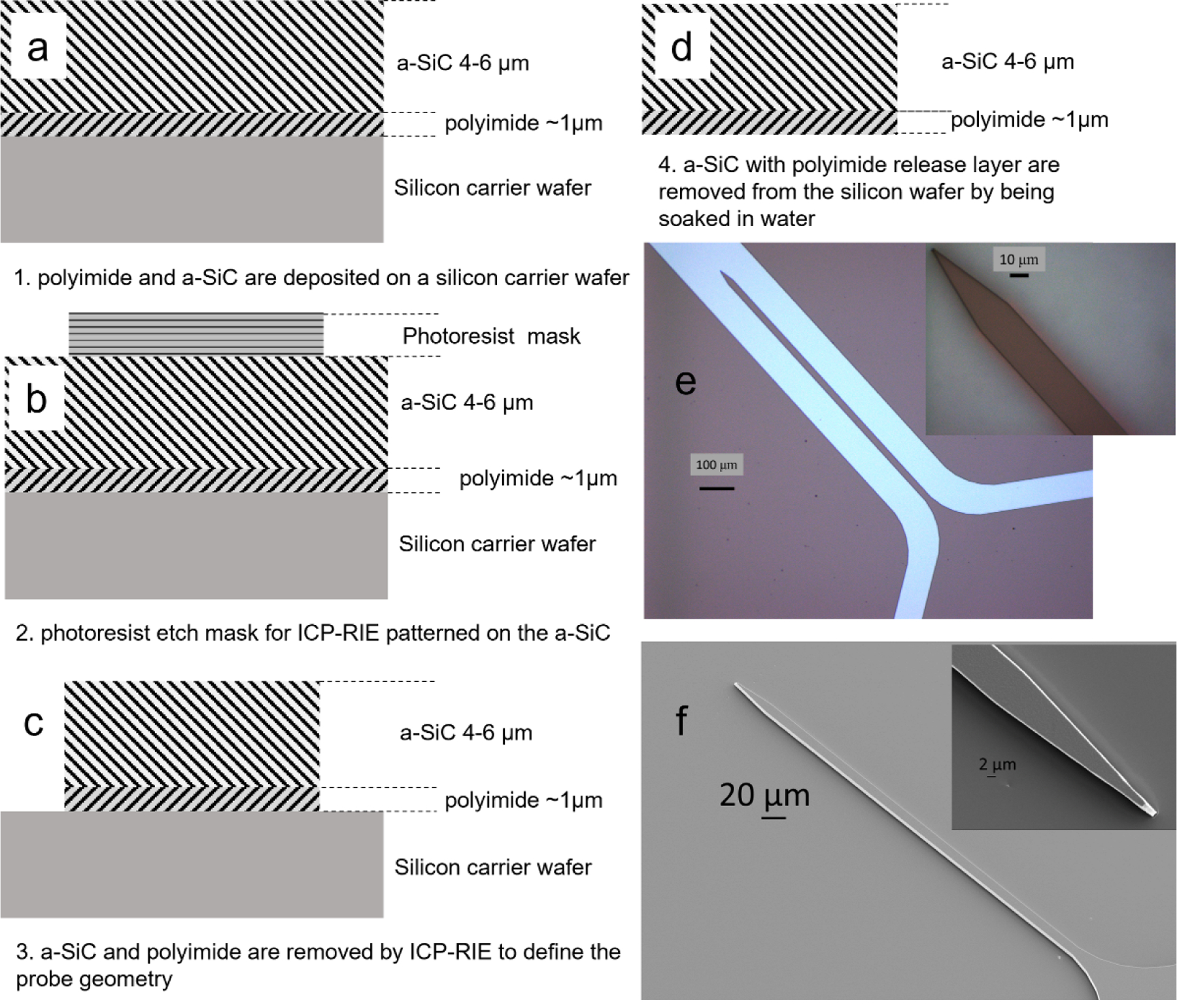
Fabrication process for non-functional probes, a) spin-coated polyimide and PECVD a-SiC are deposited on a silicon carrier wafer; b) photoresist is patterned on the a-SiC to define the probe geometry; c) a-SiC and PI are removed by ICP-RIE to create the probes; d) photoresist is removed from the probes and the probes separated from the carrier wafer by soaking in water; e) optical images of a 6 µm thick probe with a 20-µm shank width, and 1 mm shank length; f) Scanning electron microscopy (SEM) image of a single shank showing the tapered distal tip with an included angle of 11 degrees.
Table 1.
Geometries of UMEA probes
| Cross-section, μm | Length, mm |
|---|---|
| 7 × 4 | 0.5, 1, 2 |
| 20 × 4 | 0.5, 1, 2 |
| 7 × 6 | 0.5, 1, 1.5, 2 |
| 10 × 6 | 0.5, 1, 2 |
| 20 × 6 | 0.5, 1, 1.5, 2 |
2.2. Critical buckling force measurements
To determine critical buckling forces (FC) for different probe geometries, we used a precision 20-g S-beam load cell (FUTEK FSH 3868) and voltage digitizer (FUTEKFSH 03944) to measure the dynamic forces during a-SiC probe buckling against a rigid silicon wafer. To minimize sliding of the probe tip, the wafer was spin-coated with a thin (50 µm) layer of silicone polymer. The a-SiC probes and load cell were mounted to a hydraulically controlled micro drive (Kopf Instruments, USA) using super glue and dental cement (figure 2(a)). The probe tip was brought into contact with the wafer and the resultant axial force sampled at a rate of 20 Hz while driving the probe into the wafer at a speed of 5 µm/s. A surgical camera with 10–40X magnification (LEICA 10450243) was used to capture real-time videos of the probe during buckling (figure 2(b)-(c)).
Figure 2.
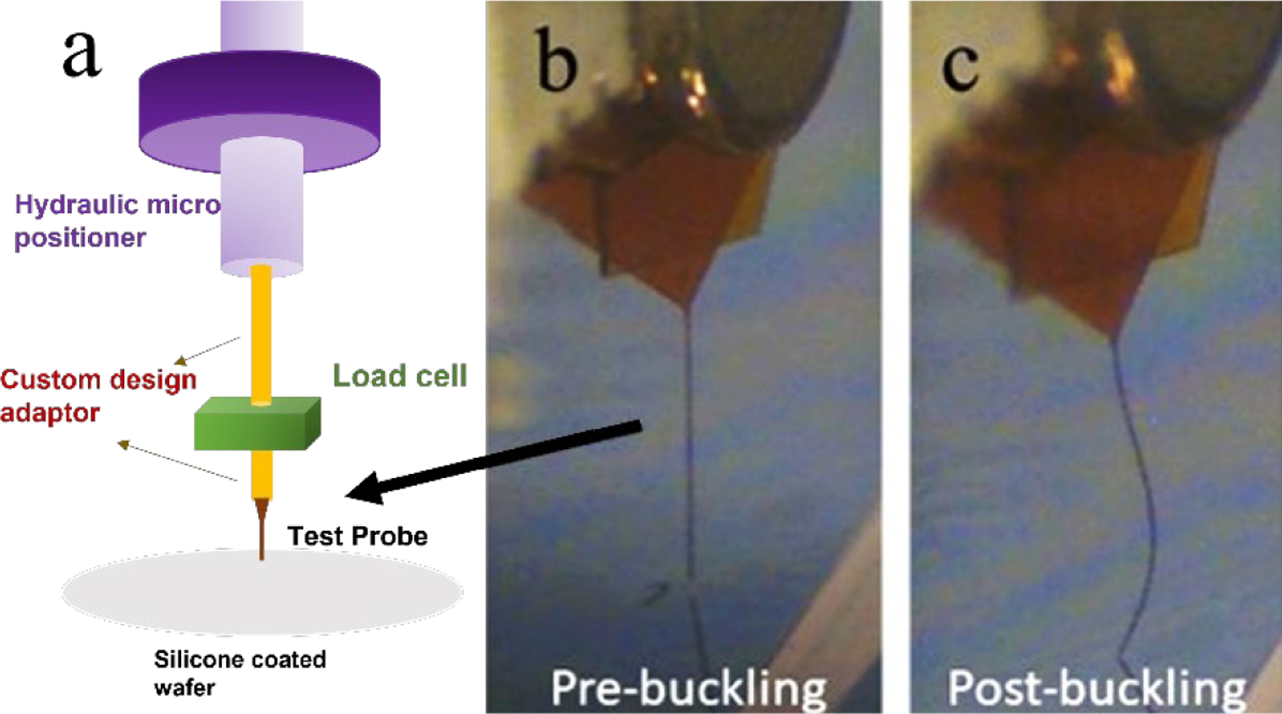
a) Schema of the force measurement apparatus used to determine critical buckling forces and force-displacement curves for agarose gel and in vivo studies; b) image from a video recording of a 2-mm long probe before contact with a silicon wafer and c) after buckling against the wafer.
2.3. Insertion into agarose gels
We also used the custom-mounted load cell to measure dynamic forces during the insertion of a-SiC probes into agarose gel phantoms. Agarose phantoms have been used previously to approximate the stiffness of brain tissue [22–25]. Here, we prepared 20-mm diameter by 10-mm thick disks of 0.8% w/w agarose by dissolving 0.16 g of agarose (source) into 20 g of deionized water. The agarose solution was heated to a liquid phase and then gelled by cooling to room temperature. Amorphous SiC probes of various geometries were inserted into the agarose at speeds of 25, 50, 100, 500 and 1000 µm/s, which is a similar range to that employed in previous studies [23,24,26–28]. The resulting axial force on the probe was measured at a sampling rate of 20–200 Hz, depending on speed, until the probe was fully inserted. A thin layer of phosphate buffered saline (PBS) was added to the surface of the gel to prevent the surface from drying out during the measurement. The peak of the axial force-displacement curve was taken as the maximum insertion force (Fm).
2.4. Insertion force measurement in rat cortex
Insertion force measurements were performed on five female Sprague-Dawley rats, using procedures carried in accordance with protocols approved by the Institutional Animal Care and Use Committee at the University of Texas at Dallas. Anesthesia was initiated with a cocktail consisting of ketamine (65 mg/kg), xylazine (13.3 mg/kg) and acepromazine (1.5 mg/kg) following established protocols [19,29]. The head of the animal was shaved, and alcohol/iodine wipes were used to disinfect the area. Later, the animals were placed in a stereotaxic frame (Kopf Model 900, David Kopf Instruments, Tujunga, CA), and inhalation anesthesia (1.5% isoflurane in 0.5 l/min of oxygen) was delivered via a nose mask while body temperature was maintained with a heating pad and monitored. After surgical-depth anesthesia was established, a mid-sagittal incision was made to expose the skull, beginning between the eyes, and extending to the level of the ears, exposing the bregma and lambda. Two rectangular craniotomies, with dimensions of 4 × 3 mm, were then drilled bilaterally into the parietal bone. The coordinates of each geometric center with respect to the intersection of bregma and midline were approximately −2 ± 2.7 mm. As the attempts to insert the probes through the dura mater were unsuccessful, the dura mater was carefully removed, and any blood was washed away from the exposed surface of the brain which was kept moist using sterile PBS during the experiments. We did not attempt to remove the pial surface for insertion force measurements. Between one and twelve probe insertions, usually of different geometries, were made in each animal. Insertion forces were measured with various randomly selected probes at several locations within one or multiple rat brain. A separation of at least 300 µm between insertion sites was maintained to minimize any overlap of surgical insertion trauma zones. Probes were considered to have buckled when they visibly failed to enter the brain and the measured force plateaued at a constant value. All animals were euthanized by overdosing with pentobarbital (120 mg/kg intraperitoneal).
3. Results
3.1. Critical Buckling Force
We quantified the critical buckling force (FC) for multiple single-shank a-SiC probes of different lengths and cross-sectional geometries that were fabricated without metallization or electrode sites. As each device was brought into contact with a rigid silicon wafer, the measured axial force increased in magnitude until it plateaued and maintained a nearly constant value, which was taken to represent FC. In each case, the probe had visibly buckled at the measured value of FC. A representative force-displacement curve is shown in figure 3. The displacement of the actuator (micropositioner) associated with buckling can be read from the right ordinate axis as the displacement from the point of contact at 62 s to the reversal of the displacement at 120 s. In this example, a linear displacement of ~0.27 mm accompanied the buckling of the probe shank. The force-time/displacement curve in figure 3 is for a probe with cross-sectional dimensions of 6 × 20 µm and length of 1 mm. The baseline force was zero prior to contact of the probe tip with the substrate; after contact, the measured compressive force increased in magnitude until the probe buckled, at which point the force value began to plateau. This behavior is similar to that reported by Joo et al [13]. The FC for this probe geometry was −0.36 mN (compressive). As the probe continued to buckle the measured force remained constant until, at 120 s, the direction of probe travel was reversed. From 125–180 s, there was a slight decrease in force as the probe straightened and at 180 s as the probe was lifted from the wafer surface and the force returned to zero.
Figure 3.
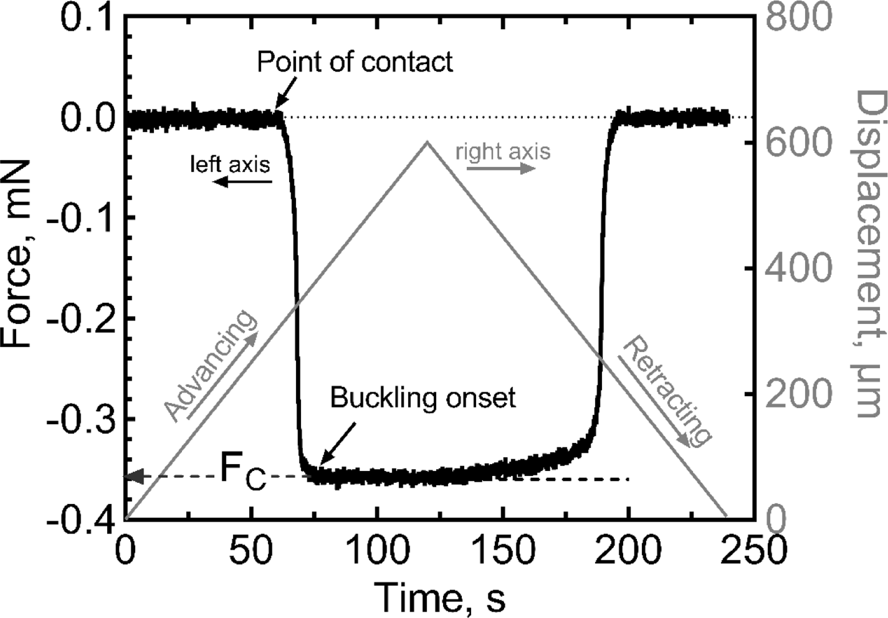
Representative force displacement curve showing an a-SiC probe with shank cross-sectional dimensions of 6 × 20 µm and length of 1 mm advanced at a constant speed of 5 µm/s into a silicon wafer. The direction of probe travel was reversed at 120 s. The critical buckling force is approximately −0.36 mN.
Measured buckling forces for probe cross-sectional dimensions of 6 × 7, 6 × 20, and 4 × 20 µm and lengths of 0.5, 1, 1.5, and 2 mm, are listed in table 2. The FC data follow the trend for Eulerian buckling as described by,
| (1) |
where E is the elastic modulus of a-SiC, I represents the minimum area-moment of inertia of the cross-section of the probe, L is the length of the probe, and n represents a factor that accounts for the boundary conditions at each end of the probe [30]. We used a value of n=2.046 for a fixed-pinned column, since the probe is fixed at one end to the actuator but free to rotate (i.e., pinned) at its point of contact with the substrate [28,30]. The reported E of a-SiC varies considerably from 80–300 GPa [31,32] and, for this reason, we did not attempt to independently confirm the value of n based on a presumed E and equation 1. The area moment of inertia I was obtained from the following relation (equation (2)),
| (2) |
where w is the width and t the thickness of the rectangular cross-sectional geometry of the probe shank. (Calculations of the moment of inertia I for non-functional probes, which have no metallization or electrode sites, were not significantly different than functional probes of similar cross-sectional geometry.) The FC values from table 2 are plotted in figure 4 with respect to 1/L2. A linear relationship between FC and 1/L2 was observed for each cross-sectional geometry. The results of the regression analysis for each cross-sectional geometry are provided in table 3.
Table 2.
Measured critical buckling forces for a-SiC probes with various cross-sections and lengths. I is the minimum area moment of inertia of the cross-section.
| Cross-section | Length, mm | FC, mN mean ± SD*, number of probes |
|---|---|---|
| 6 × 7 μm, | 0.5 | −0.71 ± 0.05, n=3 |
| I=126 μm4 | 1 | −0.15 ± 0.03, n=5 |
| 1.5 | −0.09 ± 0.01, n=4 | |
| 2.0 | −0.04 ± 0.01, n=4 | |
|
| ||
| 4 × 20 μm, | 0.5 | −0.50 ± 0.01, n=2 |
| I=107 μm4 | 1.0 | −0.13 ± 0.01, n=3 |
| 2.0 | −0.03 ± 0.003, n=3 | |
|
| ||
| 6 × 20 μm, | 0.5 | −1.26 ± 0.13, n=3 |
| I=360 μm4 | 1.0 | −0.37 ± 0.03, n=3 |
| 1.5 | −0.21 ± 0.003, n=3 | |
| 2.0 | −0.12 ± 0.01, n=2 | |
SD=Standard Deviation
Figure 4.
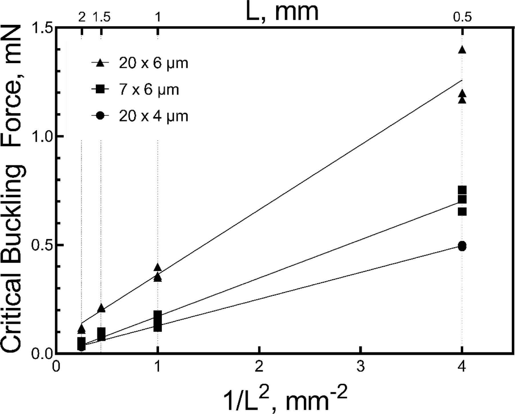
Critical buckling forces (absolute value) for a-SiC probes with various cross-sections and lengths plotted against 1/L2 measured during advance into a non-penetrable substrate, (data from Table 2).
Table 3.
Regression results for fitting FC to 1/L2, number of observations: 35
| Cross-section | Slope, mN mm2 | 95% CI* | R2adj |
|---|---|---|---|
| 6 × 7 μm | 0.176 | 0.166–0.187 | 0.988 |
| 4 × 20 μm | 0.123 | 0.119–0.127 | 0.999 |
| 6 × 20 μm | 0.298 | 0.271–0.326 | 0.984 |
CI=Confidence Interval
3.2. Insertion into agarose gel
To determine how the axial forces required for probe insertion compared to the measured values of FC, we measured the force required to insert probes of different cross-sectional geometries into a 0.8% agarose gel, which approximates the mechanical properties of neural tissue [33]. For each cross-sectional geometry, probe lengths of 0.5, 1 and 2 mm were investigated. A representative insertion force versus time response is shown in figure 5 for an a-SiC probe with a 6 × 20 µm cross-sectional geometry and a length of 2 mm. A maximum insertion force of −0.21 mN was recorded at the full 2-mm depth of probe insertion as ascertained by the displacement distance and confirmed by visual inspection. The probe speed for advancing and retracting from the gel was 100 µm/s, similar to that employed by Sridharan et al. [23].
Figure 5.
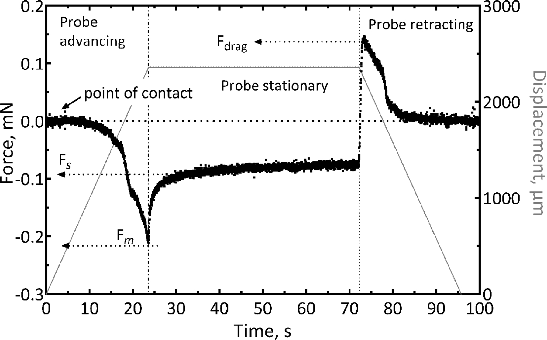
Representative force-time curve for insertion of a 6 × 20 µm cross-sectional probe with length of 2 mm into agarose gel. The insertion speed was 100 µm/s. The maximum insertion force was −0.21 mN at the point the probe was fully inserted to a depth of 2 mm. Fm represents the maximum force measured during the insertion and Fs is the steady state force measured a few seconds after the probe was held stationary. Fdrag represents the tensile force measured during retraction of the probe from the gel.
As the probe tip began to penetrate the gel, the force monotonically increased until the probe was fully inserted. The maximum force (Fm) during insertion into gel was also observed at the maximum depth of insertion. After insertion to the full length of the probe shank, the probe was held stationary, and the measured force observed to decrease until it reached a nearly constant value (Fs) (figure 5) consistent with that expected for compliant gels [34]. At this point in the experiment, the inserted probe was then fully retracted. We did not observe the gel surface compression (dimpling) reported previously for devices of larger cross-sectional area [27]. If allowed sufficient time, the force in the “probe stationary” stage relaxes to zero, reflecting the viscoelastic behavior of the gel. Full relaxation of the force to zero occurs slowly over 10–20 minutes. Retracting the shank from the gel resulted in a tensile force (Fdrag) that peaks rapidly on extraction and then decreases to baseline as the probe is fully withdrawn. In many cases, we observed some adhesion of the gel to the probe surface, which likely contributed to the tensile force measured during probe extraction.
To investigate how insertion speed influences the forces required to implant the a-SiC probes, we also repeated these experiments at a variety of insertion speeds, ranging from 25 µm/s to 1000 µm/s, for various cross-sectional probe geometries (figure 6). Data in figure 6 suggest that higher insertion speeds produce larger insertion forces. There is a clear monotonic increase in peak insertion force for the 6 × 7 µm and 6 × 10 µm probes with increasing insertion speed, and a general trend towards increasing force for the 4 × 10 µm and 6 × 20 µm probes. Multiple linear regression showed that insertion force depended significantly on insertion speed, while differences in either the area-moment of inertia of the cross-section of the probe or the probe length did not significantly influence the measured insertion force (table 4).
Figure 6.
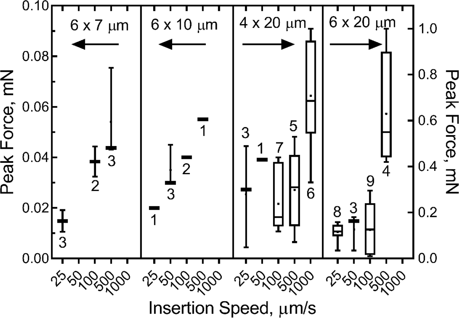
Plots of peak insertion force into agarose gel as a function of probe insertion speed and cross-sectional dimensions. The moment moments of inertia for various probe geometries were 126 µm4 (6 × 7 µm), 180 µm4 (6 ×10 µm), 107 µm4 (4 × 20 µm), and 360 µm4 (6 × 20 µm). Data were non-normally distributed (Shapiro-Wilk normality test). Whiskers represent the range of data, and box limits represent the 25% and 75% quartiles. The bar and dot represent the median and the average, respectively. Number of individual repetitions are shown for each speed.
Table 4.
Regression results for fitting FC to speed, probe length and area moment of inertia for probe insertion into 0.8% agarose gel
| Mean | P | 95% CI | |
|---|---|---|---|
| Speed, μm/s | 0.00059 mN-s/μm | <0.001 | 0.00043–0.00076 |
| Length, mm | 0.1 mN/mm | 0.053 | −0.001–0.208 |
| Moment, μm4 | 0.0001 mN/μm4 | 0.642 | −0.0003–0.0005 |
60 observations, F=19.59, R2adj =0.486
Insertion force data as a function of penetration depth into agarose gel for a 2-mm long 6 × 20 µm probe are shown in figure 7. The measured FC for this probe geometry is −0.12 mN (table 2). As the probe enters the gel, the FC increases (becomes more negative) but remains lower than the predicted critical buckling force (FC) over the full insertion depth (see discussion).
Figure 7.
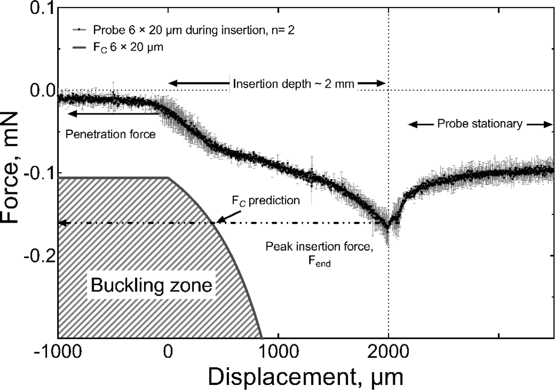
Comparison of the measured insertion force and calculated critical buckling force for the insertion of a 2-mm long, 6 × 20 μm probe into agarose gel at a speed of 100 µm/s. The measured insertion force is less than the critical buckling force and the full length of the probe was inserted into the gel without buckling.
3.3. Insertion into rat cortex
We also tested cortical insertion forces in rat using single-shank probes with a cross-sectional-area of 120 µm2 (6 × 20 µm, I=360 µm4) and lengths of 0.5, 1 and 2 mm. The 6 × 20 µm geometry was chosen for the in vivo studies because this width permits the inclusion of electrodes sites with geometric areas of 200 μm2 or greater suitable for pulsed-current neural stimulation as well as recording. Probes with this shank width had an included angle at the tip of 10 degrees. The dura was removed from the cortical surface and the force measured. Three insertion speeds of 25 µm/s, 100 µm/s and 1000 µm/s were investigated initially; however, due to the high failure rate (80%) for 1000 µm/s insertions, this speed was not evaluated in detail. A representative force-time curve for the insertion of a 2-mm probe at 25 µm/s is shown in figure 8. Unlike insertion into agarose gel, the force fluctuated notably during the initial stages of insertion and was influenced by dimpling of the cortex that preceded penetration of the shank tip into the brain parenchyma [27]. The region of visually identified cortical dimpling is indicated in figure 8 and is characterized by an initial monotonic increase in force as the depth of the dimple increases. The maximum dimple depth before the probe penetrated the brain parenchyma for this specific example was approximately 250 µm and occurred at a penetration force (Fp) of −0.095 mN. Following the initial penetration of the pia, we also observed a period of fluctuating force, which was presumably caused by the tissue slipping against the probe while the dimple relaxed. To varying degrees, these stick-slip events occurred whenever cortical dimpling was encountered [26,35]. Following the stick-slip events, the insertion force increased until the probe was fully inserted into the cortex with an Fend of approximately −0.25 mN. Once the advance of the probe was halted, the cortical tissue relaxed around the probe shank reaching an initial steady state residual force (Fs) of −0.1 mN after about 20 seconds. Similar behavior was observed in agarose gel (figure 5). The variability in insertion forces measured in cortex is reflected by the force-displacement curve in figure 9 of a similar of a 6 × 20 µm probe having a shorter 1-mm length. In the latter case, cortical dimpling was observed, but without the force ratcheting effect we associate with slip-stick relaxation of the brain around the probe as shown in figure 8. For both the 2-mm and 1-mm probe lengths, the magnitude of the insertion forces remained well below that expected to cause buckling. When buckling occurs, the insertion force plateaus and remains approximately constant and the probe does not advance into the parenchyma. This behavior is shown in figure 10 for a 6 × 20 μm, 2-mm long probe in which insertion was attempted at a speed of 1000 μm/s.
Figure 8.
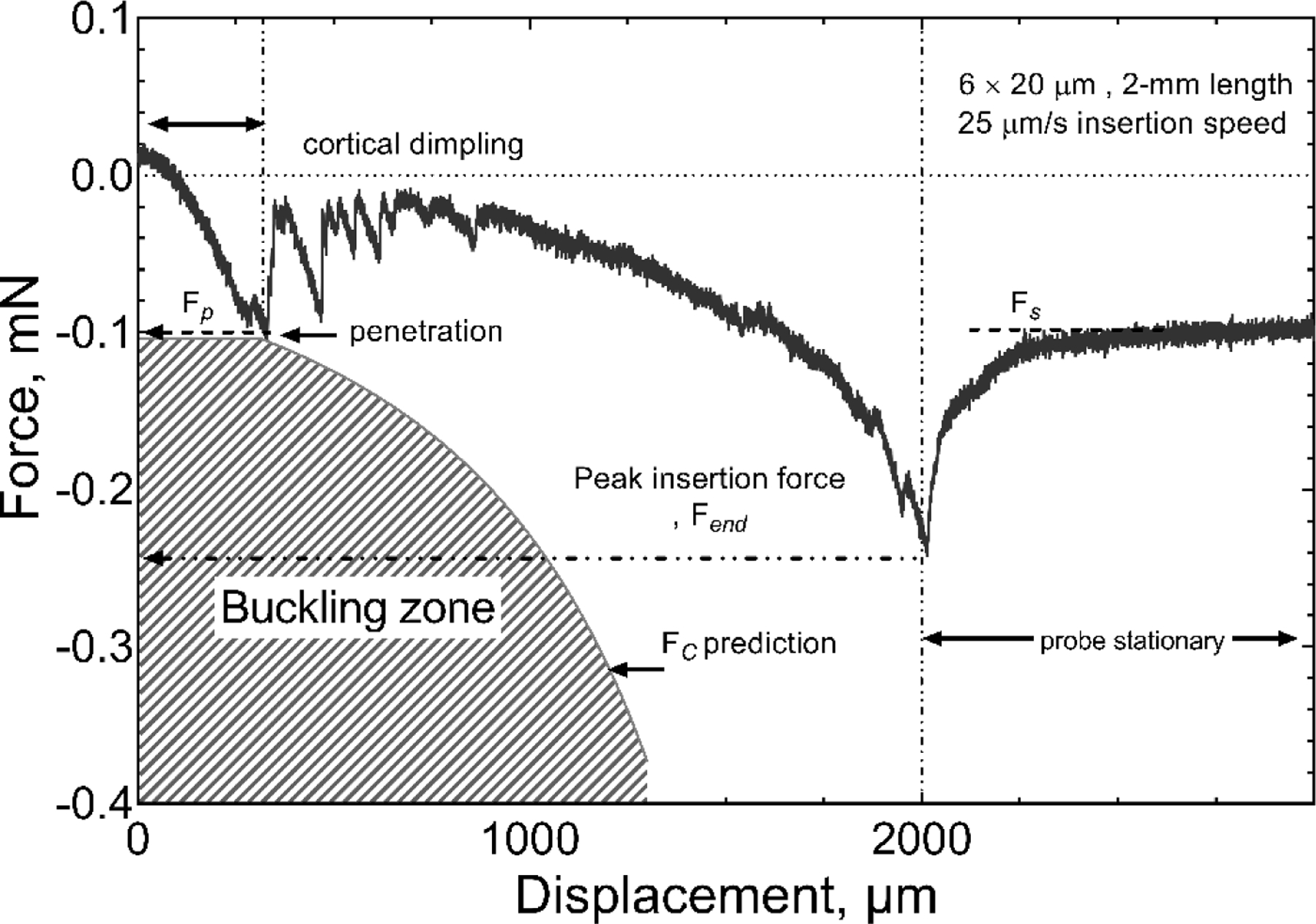
Representative force-displacement curve for insertion in rat cortex with a probe having a shank cross-section of 6 × 20 µm and length of 2 mm. The insertion speed was 25 µm/s. Fp, Fs and Fend represent the penetration force, measured force at steady state and the force measured after the full insertion, respectively.
Figure 9.
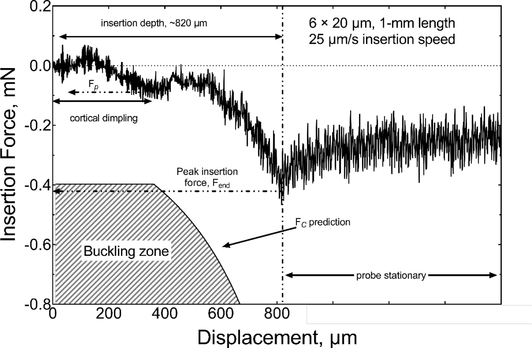
Comparison of the measured insertion force and calculated critical buckling force for the insertion of a 1-mm long, 6 × 20 µm probe into rat cortex at 25 µm/s. Cortical dimpling to a depth of ~400 µm was observed before penetration and insertion to ~820 µm without buckling.
Figure 10.
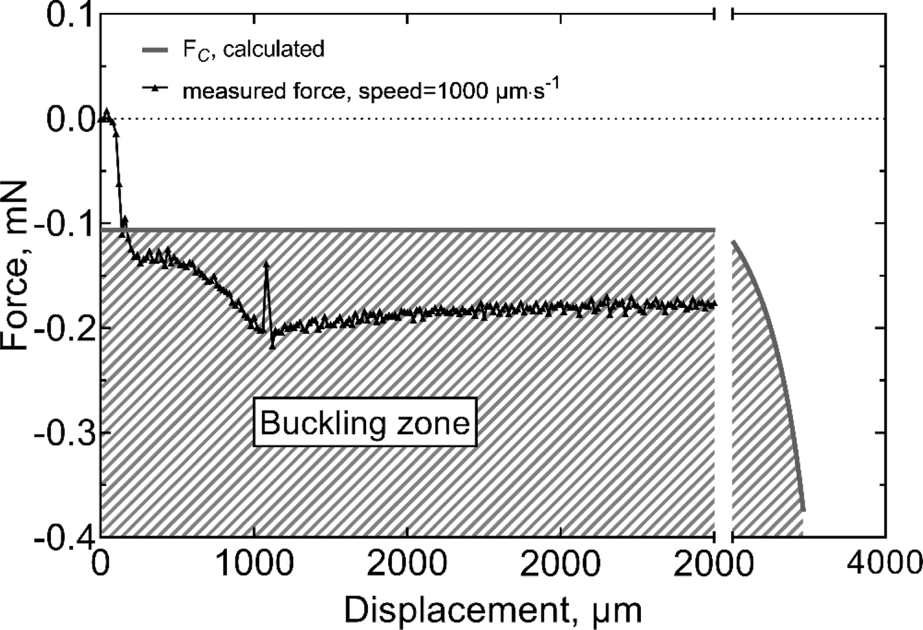
Comparison of the measured force and calculated critical buckling force for the insertion a 2-mm long, 6 × 20 µm probe into rat cortex at 1000 µm/s, during which buckling was observed
The forces Fp, Fm, Fs, and dimple depth measured during insertion into rat cortex with probes of 6 × 20 µm shank cross-sectional dimensions and lengths of 0.5 mm, 1 mm and 2 mm with their associated successful insertion rate are summarized in table 5. Fm represents the maximum force recorded during the entire insertion experiment into rat cortex. (In a few cases, this value was equal to the penetration force Fp while mostly was equal to the force after full insertion Fend). Although the number of measurements at 100 µm/s was limited to four, it is worth noting that dimpling was greatly reduced compared with 25 µm/s insertion speeds and this was apparent from visual observation and the absence of a clear point of cortical penetration in the force-displacement curves.
Table 5.
Dimple depth and characteristic forces for insertion into rat cortex.
| Probe geometry | Speed, μm/s | Dimple Depth, μm | Fp, mN | Fm, mN | Fs, mN | Success/Trials |
|---|---|---|---|---|---|---|
| 6 × 20 μm, 0.5 mm (n=6) | 25 | 384 ± 108 | −0.37 ± 0.14 | −0.21 ± 0.16 | −0.18 ± 0.28 | 6/7 |
| 6 × 20 μm, 1 mm (n=3) | 25 | 233 ± 153 | −0.25 ± 0.21 | −0.66 ± 0.18 | −0.21 ± 0.19 | 3/5 |
| 6 × 20 μm, 2 mm (n=3) | 25 | 152 ± 167 | −0.13 ± 0.05 | −0.28 ± 0.10 | −0.10 ± 0.04 | 3/5 |
| 6 × 20 μm, 2 mm (n=4) | 100 | 62 ± 124 | −0.13 ± 0.06 | −0.27 ± 0.1 | −0.09 ± 0.01 | 4/6 |
4. Discussion
The expected reduction in surgical tissue trauma and chronic FBR arising from the use of penetrating probes with reduced cross-sectional dimensions compared to typical microelectrode probes has been demonstrated [36,37]. Moreover, the effect of geometry and material coating has been previously reported by Marshall et al [28] in a polyvinyl chloride brain phantom and Andrei et al. [26] in rodent cortex. Marshall et al found insertion forces of 0.5–1 mN with carbon fiber probes having cross-sectional areas below 100 μm2 were sufficient to achieve insertion into their brain phantom. Andrei et al [26] investigated the combined effects of insertion speed, cross-sectional geometry, tip angle and material coating on insertion in rat cortex. They reported similar insertion force versus displacement responses to those we observe (figure 8), but with higher force magnitude due to the large cross-sectional area of their probes (200–400 µm wide by 150 µm thick). They also showed that Parylene-C coatings on silicon probes reduce probe-tissue friction, and consequently reducing insertion forces and promoting tissue relaxation around the probe [26]. In addition, sharper tips have been shown to decrease the magnitude of insertion forces and minimize the compression of brain [13,35,38,39]. However, there remains the challenge of inserting ultramicroelectrode-dimensioned probes into brain without buckling and deflection. Here, we studied the buckling of UMEA-dimensioned probe shanks to predict geometries that permit implantation without use of an external support such as a mechanical-guide or a dissolvable coating [13–15,40].
Thin mechanical beams subjected to compressive axial loads will buckle if the applied compressive force exceeds a critical limit [30]. Eulerian buckling theory shows that this critical buckling force depends on the geometry of the beam (i.e., its cross-section and length), as well as its mechanical properties and boundary conditions, a relationship described quantitatively by equation (1). Each UMEA shank can be modeled as a cantilevered beam, which is loaded in compression and, at the initial point of contact during insertion, pinned (i.e., free to rotate) at its tip. Our buckling data for different UMEA probe designs suggests that Eulerian buckling can reasonably describe their mechanical behavior (figure 4). During probe insertion, however, once the probe begins to penetrate the brain, the effective length of the beam (i.e., the length of the probe still above the pial surface) begins to decrease. Therefore, the critical buckling force begins to increase in proportion to the inverse square of the decreasing effective beam length (equation 1). We have observed that as each probe is implanted into the brain, the required insertion force increases monotonically, and buckling is avoided only if the critical buckling force remains greater than the applied insertion force until the probe has been fully inserted. Using equation (1), the predicted critical buckling force can be calculated for each probe as a function of the depth it has been inserted, and these values can be compared with the measured time-varying insertion forces for different probe geometries.
For example, the measured insertion force in agarose gel is compared in figure 7 with the region, shown by the hatched area, over which buckling is predicted from equation (1). If, the insertion force remains lower in magnitude than the predicted value of FC during the entire insertion process, no buckling is encountered. The increase in insertion force with increasing probe depth in the gel is expected due to viscoelastic forces on the probe which increase with contact area between the probe and gel [25]. Additional consequences of the viscoelastic behavior of the gel are the insertion rate dependence of the maximum insertion force, and the relaxation behavior of the residual force once the probe is stationary in the gel, as reported in [34,41].
Unlike the agarose gel model, insertion into cortex is complicated by tissue heterogeneity, particularly owing to the presence of blood vessels, as well as curvature of the cortical surface. We also observe dimpling of the cortical surface during insertion, which produces transient increases in the insertion force until the probe tip had been inserted fully into the parenchyma. The dimpling and its effect on the initial insertion force is shown in figure 8 for a 6 × 20 µm probe having a 2-mm length. Dimpling of the cortex was visually apparent and extended to a depth of 250 µm before the probe tip penetrated the pia. Also plotted in figure 8 is the region over which buckling would be expected to occur, based on equation (1). As seen in figure 8, the 2-mm long probe has a comparatively low buckling stress and the measured insertion force, although generally less than the buckling force, does reach the critical buckling force at the point of penetration. The probe was then inserted to a final depth of ~2 mm without the insertion force entering the buckling zone buckling, shown by the hatched area, and the probe fully inserted without buckling. At the full insertion depth, the advancement of the probe was stopped, and the measured force observed to slowly relax, consistent with the viscoelastic behavior of tissue. There is a considerably wider margin of safety for avoiding buckling as shank length is reduced, as shown in figure 9 for a 6 × 20 µm probe with a 1-mm length. Since cerebral cortical placement of electrode sites is likely to require a depth less than 2 mm, a-SiC MEAs with a cross-section of 6 × 20 mm (I=360 µm4) should be implantable into rat cortex using insertion speeds of 100 μm/s or slower. At a higher insertion speed of 1000 μm/s, however, buckling was encountered with 2-mm long probes with 6 × 20 µm cross-sectional dimensions. A characteristic constant force is observed in the force-displacement curve (figure 10) and the linear displacement of the proximal base of the array held in the microdrive is accommodated by the lateral displacement of the probe shank.
A notable uncertainty in estimating buckling forces using Euler’s equation (equation (1)) is the selection of the parameter n which is based on assumed end constraints of the probe shank. Indeed, visualization of shank buckling geometry from video recordings during critical buckling force measurements (figure 4), or in agarose gel or cortex, was difficult to interpret with respect to the constraint at the shank tip. For this reason, we adopted the constraints proposed by [30] and [28], which allow free rotation at the brain surface and a fixed perpendicular orientation at the base of the probe. Based on these constraints, we selected an n of 2.046 for our calculation of the initial buckling force. We also assumed that the longitudinal axis of the shank remains parallel to the direction of insertion. If, however, the rotation of the probe tip is constrained, perhaps by modifying the geometry of the tip, the critical buckling force should increase by nearly a factor of 2, since n=4 for a fixed-fixed column [30]. Importantly, this increase in the mechanical performance of the probe can be accomplished without changing the geometry of the cross-section or adding an external mechanical support. Since we did not incorporate this fixed-fixed boundary condition into our estimates of FC, our data likely underestimate the actual buckling force of the probe, especially once it has begun penetrating the tissue.
In order to predict buckling forces over a range of cross-sectional geometries and shank lengths, we linearized the data in figure 4 by taking the base-2 logarithm of the Euler equation and fitting the measured buckling forces by linear regression to the linearized model represented by equation (3).
| (3) |
The coefficients obtained from the regression were b0= 31.4 (95% CI: 23.6–39.3), b1=0.863 (95% CI: 0.756–0.969) and b2=0.939 (95% CI: 0.884–0.993) (F=793, adj. R2=0.979). We then calculated predicted critical buckling forces for various probe cross-sectional geometries and lengths as shown in figure 11. Included in figure 11 are lines representing the minimum and maximum measured penetration forces in rat cortex with 6 × 20 µm probes from the data in table 5 The variability of the penetration forces in rat cortex is significant, as exemplified by Fm for the 6 × 20 μm, 1 mm probe in table 5 and is associated in part with the uncertainty created by dimpling of the cortex that may produce a ratcheting of the measured force until the probe tip has penetrated the cortex and the dimpling resolved. This variability and the ratcheting of the penetration force can be appreciated from comparison of the force-displacement curves in figure 8 and figure 9. We also observed that buckling during penetration into the cortex could be transient and, although the calculated buckling force might be exceeded, a probe exhibiting mild buckling against the pial surface may abruptly penetrate into cortex and the probe straighten. As the depth of the probe in the cortex increases, the ratcheting decreases and there is a transition to a slowly increasing force which we associate with increased drag from the tissue as the brain-probe contact area increases with penetration depth. Additionally, higher penetration forces were observed if the probe encountered a blood vessel, under which circumstance, we typically observed a deflection of the probe from its intended penetration direction or buckling and failure to penetrate the brain. Clearly, avoiding blood vessels, at the very least those visible on the cortical surface, is desirable to avoid excessive penetration forces.
Figure 11.
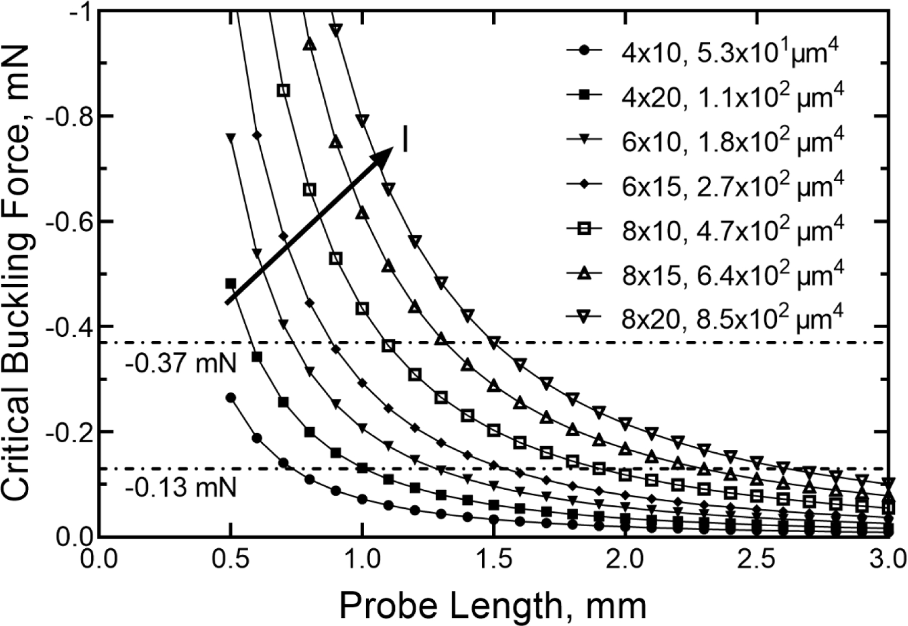
Calculated critical buckling force versus probe length for a range of cross-sectional geometries with associated area moments of inertia (I). The horizontal lines indicate the average minimum compressive (−0.13 mN) and maximum compressive (−0.37 mN) cortical penetration forces measured in rat for different probe geometries. The arrow shows the direction of increasing I of the probe cross-section.
In regard to unaided insertion, it is clear from the calculations in figure 11 that probes with shank lengths greater than 3 mm are unlikely to insert without buckling unless the penetration force through the pia is reduced or the probe stiffness increased. The shank tips for the measurements reported in table 5 had a taper angle of 10° and it may be possible to reduce the penetration force by decreasing the taper angle. In the latter case, it may also be possible to increase the probe cross-sectional dimensions while retaining a low probe bending stiffness. Using equation (2), we can predict the critical buckling forces for various probe geometries. For example, increasing the thickness of the probe to 10 μm results in a moment of inertia of 1.7 × 103 μm4 for a 20 μm wide probe, resulting in a calculated critical buckling force of −0.18 mN for a 3-mm long shank. From the calculations shown in figure 11, with this critical buckling force the probe might be expected to successfully penetrate into cortex. Further, following the analysis by Stiller et al. [12] and using an a-SiC elastic modulus of 300 GPa [21], the calculated bending stiffness for a 3-mm long probe with a 10 × 20 μm cross-section is −0.057 N/m, which remains within a range expected to minimize tissue response associated with mechanical mismatch between the brain tissue and the probe.
As indicated by the data in figure 6 and table 4, we have shown that insertion speed is important in determining the peak insertion force, which occurs at the point of full insertion of the probe into the brain. We suspect that reducing the insertion speed allows more time for the agarose gel, or tissue for in vivo preparations, to relax around the probe reducing the magnitude of the insertion force at the slower speeds. During cortical insertion, however, the slower speeds were associated with cortical dimpling that produced notable variability and rapid transient changes in the measured force during the process of penetration and initial relaxation of the dimple around the probe. Reduced cortical dimpling at higher insertion speeds has been reported previously [38] and emphasizes the dynamic nature of tissue deformation compared with the agarose gel model used in the present study, which is clearly limited in this respect. The ratcheting of the force during initial penetration into cortex has also been reported previously for penetrations into gel and is associated with stick-slip events at the probe-gel interface [35]. Although we did not investigate surface coatings for moderating the stick-slip events that give rise to the force transients, surface modification of the probes with non-adhesive coatings is expected to reduce the magnitude of the forces associated with relaxation of the dimple. Regarding to insertion speed with cortical placements, we observed almost no dimpling at an insertion speed of 1000 µm/s; however, attempts to insert the a-SiC probes at this speed frequently resulted in probe fracture. For this reason, it was necessary to limit cortical insertion speeds to 100 µm/s, which minimized, but did not eliminate, dimpling while allowing insertion without buckling.
5. Conclusion
We have examined the mechanics and buckling behavior of a-SiC probes inserted into agarose gel and rat cortex to determine probe geometries that will likely insert into brain parenchyma without external mechanical supports or temporary stiffening coatings. Based on simple mechanical modeling and measurements of critical buckling force as a function of probe geometry we defined an insertion-depth-dependent critical buckling force that allowed predictions, based on probe geometry, of whether insertion could be achieved without buckling. The work also demonstrated the importance of insertion speed and, for cortical insertions, the compromise between minimizing cortical dimpling at slow insertion speeds and avoiding buckling at high insertion speeds. Although we employed very basic mechanical modeling, the approach provides guidance in probe design for both deeper insertions into rodent brain and insertion into the cortex of larger animals.
Acknowledgments
The authors would like to acknowledge the assistance of Ayah Layth Al Rubaye for data collection, Dr. Atefeh Ghazavi, Dr. Ana Hernandez-Reynoso and Dr. Alexandra Joshi-Imre for invaluable advice throughout the study. This work was supported by the National Institutes of Health under grant R01NS104344.
References
- [1].Normann RA and Fernandez E 2016. Clinical applications of penetrating neural interfaces and Utah Electrode Array technologies J. Neural Eng 13 061003. [DOI] [PubMed] [Google Scholar]
- [2].Homer ML, Nurmikko A V, Donoghue JP and Hochberg LR 2013. Sensors and Decoding for Intracortical Brain Computer Interfaces Annu. Rev. Biomed. Eng 15 383–405 [DOI] [PMC free article] [PubMed] [Google Scholar]
- [3].Kim C, Jeong J and Kim SJ 2019. Recent progress on non‐conventional microfabricated probes for the chronic recording of cortical neural activity Sensors 19 1–23 [DOI] [PMC free article] [PubMed] [Google Scholar]
- [4].Luan L et al. 2017. Ultraflexible nanoelectronic probes form reliable, glial scar–free neural integration Sci. Adv 3 1–9 [DOI] [PMC free article] [PubMed] [Google Scholar]
- [5].Yoshida Kozai T D, Langhals NB, Patel PR, Deng X, Zhang H, Smith KL, Lahann J, Kotov NA and Kipke DR 2012. Ultrasmall implantable composite microelectrodes with bioactive surfaces for chronic neural interfaces Nat. Mater 11 1065–73 [DOI] [PMC free article] [PubMed] [Google Scholar]
- [6].McConnell GC, Rees HD, Levey AI, Gutekunst CA, Gross RE and Bellamkonda R V 2009. Implanted neural electrodes cause chronic, local inflammation that is correlated with local neurodegeneration J. Neural Eng 6 056003. [DOI] [PubMed] [Google Scholar]
- [7].Guitchounts G, Markowitz JE, Liberti WA and Gardner TJ 2013. A carbon-fiber electrode array for long-term neural recording J. Neural Eng 10 046016. [DOI] [PMC free article] [PubMed] [Google Scholar]
- [8].McCreery D, Cogan S, Kane S and Pikov V 2016. Correlations between histology and neuronal activity recorded by microelectrodes implanted chronically in the cerebral cortex J. Neural Eng 13 036012. [DOI] [PMC free article] [PubMed] [Google Scholar]
- [9].Barrese JC, Rao N, Paroo K, Triebwasser C, Vargas-Irwin C, Franquemont L and Donoghue JP 2013. Failure mode analysis of silicon-based intracortical microelectrode arrays in non-human primates J. Neural Eng 10 066014. [DOI] [PMC free article] [PubMed] [Google Scholar]
- [10].Patel PR, Zhang H, Robbins MT, Nofar JB, Marshall SP, Kobylarek MJ, Kozai TDY, Kotov NA and Chestek CA 2016. Chronic in vivo stability assessment of carbon fiber microelectrode arrays J. Neural Eng 13 066002. [DOI] [PMC free article] [PubMed] [Google Scholar]
- [11].Seymour JP and Kipke DR 2006. Fabrication of Polymer Neural Probes with Sub-cellular Features for Reduced Tissue Encapsulation 2006 International Conference of the IEEE Engineering in Medicine and Biology Society pp 4606–9 [DOI] [PubMed] [Google Scholar]
- [12].Stiller AM, Black BJ, Kung C, Ashok A, Cogan SF, Varner VD and Pancrazio JJ 2018. A meta-analysis of intracortical device stiffness and its correlation with histological outcomes Micromachines 9 443. [DOI] [PMC free article] [PubMed] [Google Scholar]
- [13].Joo HR. et al. A microfabricated, 3D-sharpened silicon shuttle for insertion of flexible electrode arrays through dura mater into brain. J. Neural Eng. 2019;16:066021. doi: 10.1088/1741-2552/ab2b2e. [DOI] [PMC free article] [PubMed] [Google Scholar]
- [14].Zhang S, Wang C, Linghu C, Wang S and Song J 2021. Mechanics Strategies for Implantation of Flexible Neural Probes J. Appl. Mech 88 1–12 [Google Scholar]
- [15].Apollo NV, Murphy B, Prezelski K, Driscoll N, Richardson AG, Lucas TH and Vitale F 2020. Gels, jets, mosquitoes, and magnets: a review of implantation strategies for soft neural probes J. Neural Eng 17 041002. [DOI] [PMC free article] [PubMed] [Google Scholar]
- [16].Lee KK, He J, Singh A, Massia S, Ehteshami G, Kim B and Raupp G 2004. Polyimide-based intracortical neural implant with improved structural stiffness J. Micromechanics Microengineering 14 32–7 [Google Scholar]
- [17].Shoffstall AJ, Srinivasan S, Willis M, Stiller AM, Ecker M, Voit WE, Pancrazio JJ and Capadona JR 2018. A Mosquito Inspired Strategy to Implant Microprobes into the Brain Sci. Rep 8 1–10 [DOI] [PMC free article] [PubMed] [Google Scholar]
- [18].Ghazavi A, González-González MA, Romero-Ortega MI and Cogan SF 2020. Intraneural ultramicroelectrode arrays for function-specific interfacing to the vagus nerve Biosens. Bioelectron 170 112608. [DOI] [PMC free article] [PubMed] [Google Scholar]
- [19].Deku F, Cohen Y, Joshi-Imre A, Kanneganti A, Gardner TJ and Cogan SF 2018. Amorphous silicon carbide ultramicroelectrode arrays for neural stimulation and recording J. Neural Eng 15 016007. [DOI] [PMC free article] [PubMed] [Google Scholar]
- [20].Diaz-Botia CA, Luna LE, Neely RM, Chamanzar M, Carraro C, Carmena JM, Sabes PN, Maboudian R and Maharbiz MM 2017. A silicon carbide array for electrocorticography and peripheral nerve recording J. Neural Eng 14 056006. [DOI] [PubMed] [Google Scholar]
- [21].Deku F, Frewin CL, Stiller A, Cohen Y, Aqeel S, Joshi-Imre A, Black B, Gardner TJ, Pancrazio JJ and Cogan SF 2018. Amorphous silicon carbide platform for next generation penetrating neural interface designs Micromachines 9 480. [DOI] [PMC free article] [PubMed] [Google Scholar]
- [22].Woolley AJ, Desai HA and Otto KJ 2013. Chronic intracortical microelectrode arrays induce non-uniform, depth-related tissue responses J. Neural Eng 10 026007. [DOI] [PMC free article] [PubMed] [Google Scholar]
- [23].Sridharan A, Nguyen JK, Capadona JR and Muthuswamy J 2015. Compliant intracortical implants reduce strains and strain rates in brain tissue in vivo J. Neural Eng 12 036002. [DOI] [PMC free article] [PubMed] [Google Scholar]
- [24].Casanova F, Carney PR and Sarntinoranont M 2014. In vivo evaluation of needle force and friction stress during insertion at varying insertion speed into the brain J. Neurosci. Methods 237 79–89 [DOI] [PMC free article] [PubMed] [Google Scholar]
- [25].Normand V, Lootens DL, Amici E, Plucknett KP and Aymard P 2000. New insight into agarose gel mechanical properties Biomacromolecules 1 730–8 [DOI] [PubMed] [Google Scholar]
- [26].Andrei A, Welkenhuysen M, Nuttin B and Eberle W 2012. A response surface model predicting the in vivo insertion behavior of micromachined neural implants J. Neural Eng 9 016005. [DOI] [PubMed] [Google Scholar]
- [27].Sridharan A, Rajan SD and Muthuswamy J 2013. Long-term changes in the material properties of brain tissue at the implant-tissue interface J. Neural Eng 10 066001. [DOI] [PMC free article] [PubMed] [Google Scholar]
- [28].Marshall SP, Lin WC, Patel PR, Shih AJ and Chestek CA 2016. Effects of geometry and material on the insertion of very small neural electrode Proceedings of the Annual International Conference of the IEEE Engineering in Medicine and Biology Society, vol 2016 pp 2784–8 [DOI] [PubMed] [Google Scholar]
- [29].Subbaroyan J, Martin DC and Kipke DR 2005. A finite-element model of the mechanical effects of implantable microelectrodes in the cerebral cortex J. Neural Eng 2 103–13 [DOI] [PubMed] [Google Scholar]
- [30].Timoshenko S 1961. Theory of eleatic stability (New York: McGraw-Hill; ) [Google Scholar]
- [31].El Khakani M A, Chaker M, Jean A, Boily S, Kieffer JC, O’Hern ME, Ravet MF and Rousseaux F 1994. Hardness and Young’s Modulus of Amorphous a-SiC thin Films Determined by Nanoindentation and Bulge Tests J. Mater. Res 9 96–103 [Google Scholar]
- [32].Xue K, Niu L and Shi H 2011. Mechanical properties of amorphous silicon carbide Silicon Carbide: Materials, Processing and Applications in Electronic Devices (Rijeka: InTech; ) Mukherjee M pp 3–22 [Google Scholar]
- [33].McIlvain G, Ganji E, Cooper C, Killian ML, Ogunnaike BA and Johnson CL 2019. Reliable preparation of agarose phantoms for use in quantitative magnetic resonance elastography J. Mech. Behav. Biomed. Mater 97 65–73 [DOI] [PMC free article] [PubMed] [Google Scholar]
- [34].Hosseini NH, Hoffmann R, Kisban S, Stieglitz T, Paul O and Ruther P 2007. Comparative study on the insertion behavior of cerebral microprobes Annu. Int. Conf. IEEE Eng. Med. Biol. - Proc 4711–4 [DOI] [PubMed]
- [35].Obaid A, Wu Y, Hanna M, Jaidar O, Nix W and Melosh N 2020. Ultra-sensitive measurement of brain penetration with microscale probes for brain machine interface considerations ( 10.1101/2020.09.21.306498) (accessed 22 September 2020) [DOI]
- [36].Polikov VS, Tresco PA and Reichert WM 2005. Response of brain tissue to chronically implanted neural electrodes J. Neurosci. Methods 148 1–18 [DOI] [PubMed] [Google Scholar]
- [37].Kozai TDY, Gugel Z, Li X, Gilgunn PJ, Khilwani R, Ozdoganlar OB, Fedder GK, Weber DJ and Cui XT 2014. Chronic tissue response to carboxymethyl cellulose based dissolvable insertion needle for ultra-small neural probes Biomaterials 35 9255–68 [DOI] [PubMed] [Google Scholar]
- [38].Sharp AA, Ortega AM, Restrepo D, Curran-Everett D and Gall K 2009. In vivo penetration mechanics and mechanical properties of mouse brain tissue at micrometer scales IEEE Trans. Biomed. Eng 56 45–53 [DOI] [PMC free article] [PubMed] [Google Scholar]
- [39].Fekete Z, Németh A, Márton G, Ulbert I and Pongrácz A 2015. Experimental study on the mechanical interaction between silicon neural microprobes and rat dura mater during insertion J. Mater. Sci. Mater. Med 26 1–9 [DOI] [PubMed] [Google Scholar]
- [40].Wu F, Tien LW, Chen F, Berke JD, Kaplan DL and Yoon E 2015. Silk-backed structural optimization of high-density flexible intracortical neural probes J. Microelectromechanical Syst 24 62–9 [Google Scholar]
- [41].Roberts JJ, Earnshaw A, Ferguson VL and Bryant SJ 2011. Comparative study of the viscoelastic mechanical behavior of agarose and poly(ethylene glycol) hydrogels J. Biomed. Mater. Res. - Part B Appl. Biomater 99 B 158–69 [DOI] [PubMed] [Google Scholar]


