Abstract
This proof of concept describes the use of evoked electromyographic (EMG) activation of the facial nerve for intraoperative monitoring of the electrode insertion during cochlear implantation (CI). Intraoperative EMG measurements from the facial nerve were conducted in nine patients undergoing CI implantation. Electric current pulses were emitted from contacts on the CI array during and immediately after electrode insertion. For control, the results of EMG measurements were compared to postoperative flat panel volume computed tomography scans with secondary reconstruction (fpVCTSECO). During insertion, the EMG response evoked by the electrical stimulation from the CI was growing with the stimulating contact approaching the facial nerve and declined with increasing distance. After full insertion, contacts on the apical half of the CI array stimulated higher EMG responses compared with those on the basal half. Comparison with postoperative imaging demonstrated that electrode contacts stimulating high EMG responses had the shortest distances to the facial nerve. It could be demonstrated that electrically evoked EMG activation of the facial nerve can be used to monitor the progress during CI electrode insertion and to control the intracochlear electrode position after full insertion.
Subject terms: Neuroscience, Medical research, Neurology, Engineering
Introduction
Cochlear implantation (CI) has developed as the most effective rehabilitation method for patients with high degrees of hearing loss over the last decades1. Presupposition for a good speech understanding is the correct position of the electrode in the cochlea. Thus, an unfavorable intracochlear placement of the electrode like dislocation or a tip fold over has to be avoided, since this will lead to an inappropriate stimulation of the neuronal structures in the cochlea2,3. In a recent review it was described, that incorrect electrode position, like incomplete insertion or kinking occurs more often in straight flexible electrodes, while electrode tip-fold over can more often be detected in pre-formed electrodes4. On the other hand the correct positioning of the electrode in combination with an anatomically based selection of electrode stimulation can lead to a better speech understanding, since an optimized cochlear coverage can be obtained5–10. To control the position of the electrode, different techniques are available either real-time during insertion or after the insertion process. Real-time control is possible using intraoperative imaging. The only technique, which can directly detect electrode position, is the fluoroscopy11–13. Disadvantages of this technique are that the scan has to be performed in the Stenver´s projection and the ionizing radiation exposure at least to the surgeon and the patient. In addition, real-time monitoring of the electrode insertion process is possible by electrocochleography (ECochG). During ECochG recording of signals elicited via hair cells and auditory nerve fibers the relative position of the electrode can be measured14. Increasing signal amplitudes in intracochlear ECochG recordings could be observed during CI electrode insertion15. However, as ECochG recordings depend on responses of residual hearing function of the cochlear14, patients can show different patterns of signal behavior16 impeding the usage of ECochG as a tool to locate the CI array’s position.
Different tools have been developed to intraoperatively detect electrode dislocation or malposition either using electrode-neuronal interactions or systems, which use the electric activity of the implant. By the measurement of electrically induced compound action potentials the scalar location17 and a tip fold over18 can be detected. In addition, the impedances19 or the spread of excitations20 can be used to detect an unfavorable electrode position. After the insertion or after the operation radiological imaging is normally used to examine the position of the electrode. Various systems are available, which mostly use ionizing radiation to control the electrode position3,10,11, but there is ongoing research to use magnetic resonance imaging (MRI) for control after cochlear implantation21.
Facial nerve monitoring (FNM) is widely used in neurosurgical22, neurotological23,24 and other head and neck interventions, such as parotid surgery25. By FNM, the electromyographic activity (EMG) of the muscles innervated by the facial nerve is monitored to measure the function of the seventh cranial nerve indirectly. In CI, FNM is widely used to avoid unintended nerve injury during drilling in the mastoid and the posterior tympanotomy26, but in some studies it was shown, that the application of FNM does not reduce the risk of harming the facial nerve27. FNM is also used for navigation in robotic cochlear implantation28.
CIs can in principle stimulate the facial nerve electrically. This effect is the basis of postoperative facial nerve stimulation (FNS), a rare but unwanted side effect of cochlear implantation. Typical symptoms caused by FNS, are involuntary twitching of facial muscles or even painful spasm of facial muscles29. Postoperative FNS may be facilitated by a number of known conditions, such as otosclerosis30,31, cochlear malformations32 or in cases with a significantly reduced thickness of bone separating the upper basal turn of the cochlea and the labyrinthine segment of the facial nerve33,34.
The results of a computational model by Frijns et al.35, suggested that otosclerosis can cause the stimulation threshold of the facial nerve to lie within the electrical dynamic range of the CI user. FNS occurring post implantation can be reduced by using triphasic pulse stimulation36,37, electrode repositioning, change of implant type or finally by explantation38. On the other hand, FNS can theoretically be triggered in any CI user if sufficiently high stimulation levels are applied36. However, as these stimulation levels are above the maximum comfortable loudness level in CI users who do not exhibit the previously described conditions, they can only be applied in anesthetized subjects.
Since all the previously mentioned measures to control for the intracochlear positioning of the electrode have disadvantages there is still a demand for additional tools to provide the surgeon with real-time feedback during the implantation procedure. For this purpose, the aim of the present study was to develop a new electrophysiological technique. In this regard, FNS, which is normally regarded as an unwanted side effect of CI, was intentionally evoked during surgery and evaluated for its applicability to estimating the electrode position.
The basic hypothesis is that the EMG signal induced by the stimulation of electrode contacts in close proximity to the facial nerve is different to distant electrode contacts. Thus, the different signals can possibly be used to estimate the relative distance of the respective electrode contact to the facial nerve. To test this, a concept was developed in which the most apical electrode contact was used for FNS during insertion. Hypothetically, the EMG signal will rise in real-time, when the electrode contact approximates to the facial nerve in its labyrinthine portion. After passing the facial nerve and during increase of the distance the EMG signal should decline. By this procedure a pass of the electrode contact at the area of the facial nerve can be measured, which is a sign of a relative progress of insertion. After full insertion, stimulation is performed from every electrode contact. Hypothetically, the EMG signal should be highest for the electrode contact closest to the facial nerve. Thus, a map can be generated, which shows the distance between every contact and the facial nerve, which could be used to measure full insertion.
Methods
Subjects
The study was performed in 9 adult patients (Hereafter referred to as subjects and abbreviated as S1–S9), who underwent cochlear implantation at the Department of Oto-Rhino-Laryngology, Plastic, Aesthetic and Reconstructive Head and Neck Surgery at the University of Wuerzburg. Seven women and 2 men were included, ranging in age from 29 to 84 (mean = 53.67, SD = 22.72) years (see Table 1 for demographic details). All subjects fulfilled the indication for cochlear implantation according to the German Sk2 guideline for cochlear implantation and were implanted with a SNYCHRONY2® cochlear implant system from the manufacturer MEDEL GmbH (Innsbruck, Austria). This manufacturer offers a range of electrode types with different array lengths to provide an optimal fit of the implant to the patient's anatomy. The participating subjects were implanted with 4 different electrode types (see Table 1). Table 2 lists the electrode types used, their respective array length, and the spacing between the individual contacts. In the present study, the electrode contacts on the arrays were numbered from apical to basal in ascending order.
Table 1.
Demographic details of the subjects. Subjects are numbered according to the order in which they participated in the study.
| Subject | Age | Sex | Electrode type | Etiology |
|---|---|---|---|---|
| S1 | 34 | F | Standard | Otosclerosis |
| S2 | 29 | F | FLEX28 | Neurofibromatosis type II |
| S3 | 84 | F | FLEX28 | Idiopathic |
| S4 | 71 | M | FLEX28 | Idiopathic |
| S5 | 57 | F | Standard | Idiopathic |
| S6 | 58 | F | FLEX28 | Sudden sensorineural hearing loss |
| S7 | 76 | F | FLEXsoft | Sudden sensorineural hearing loss |
| S8 | 32 | M | FLEX24 | Idiopathic |
| S9 | 32 | F | FLEX24 | Idiopathic |
Table 2.
Details of the different electrode types included.
| Electrode type |
Electrode array length [mm] |
Active stimulation length [mm] |
Intercontact spacing [mm] |
|---|---|---|---|
| Standard | 31.5 | 26.4 | 2.4 |
| FLEXsoft | 31.5 | 26.4 | 2.4 |
| FLEX28 | 28.0 | 23.1 | 2.1 |
| FLEX24 | 24.0 | 20.9 | 1.9 |
The study was performed following the declaration of Helsinki and approved of the Ethics Committee of the University of Wuerzburg (315/15_z). Prior to surgery, all subjects were informed about the study and gave their written informed consent.
Experimental setup
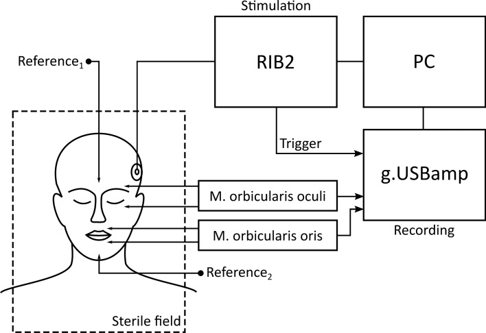
The experimental setup (see Figure 1) was based on the systems introduced by Bahmer et al.36. It consisted of a research interface box 2 (RIB2; Department of Ion Physics and Applied Physics at the University of Innsbruck, Austria) and a g.USBamp biosignal amplifier (g.tec GmbH, Schiedlberg, Austria) connected to a laptop computer (2.5 GHz Dual Core Intel CPU and 8 GB RAM). All stimulation and recording parameters were controlled via a graphical user interface programmed with the software Matlab R2017b (The MathWorks Inc., Natick, USA). The RIB2 converted the stimulation parameters into commands that were sent to the subject’s CI via a telemetric transmitter coil. The biosignal amplifier recorded the EMG response to the stimulation pulses via subcutaneous needle electrodes, which were inserted ipsilaterally into two different groups of muscles innervated by the facial nerve. The EMG channel recording the EMG activity of the M. orbicularis oculi measured the potential differences between an electrode above the eyebrow and one below the eye. The electrodes of the channel recording the EMG activity of the M. orbicularis oris were inserted above the upper lip and below the lower lip. The reference electrodes were placed in inactive areas on the forehead and the chin. It was verified that all impedances were below 5 kΩ. To synchronize stimulation and EMG recordings, the RIB2 emitted a trigger signal on the onset of each pulse. The trigger signal was fed to an input of the biosignal amplifier. The inputs of the biosignal amplifier were sampled at a rate of 38.4 kHz. The digitized signals were stored on the hard drive of the computer.
Figure 1.
Experimental setup for intraoperative EMG recordings. The setup consisted of a PC for stimulation and measurements control, a research CI interface (RIB2) for stimulation and a g.USBamp biosignal amplifier to record two EMG channels.
Stimulation parameters
The stimulation consisted of biphasic pulses with cathodic-leading phase applied in monopolar mode. The phase duration of each pulse was set to 150 µs and the interphase gap to 2.1 µs. For each measurement, 2 subsequent pulses were emitted with a rate of 100 pulses per second.
Real-time measurements
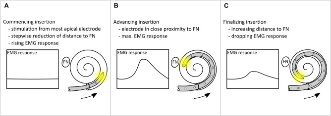
The procedure to measure the electrode insertion in real-time included the following steps: First, the surgeon inserted two electrode contacts into the tympanic scale and paused while the test conductor started the stimulation from the most apical contact with a low current level. If the applied current level did not evoke an EMG response, the current level was carefully increased until an EMG response was recorded that was just visually discernable from the background noise of the biosignal amplifier. The following step included the surgeon continuing the insertion by the next two electrode contacts and then pausing. During the pause, stimulation was performed with the current level determined in the first step and the corresponding EMG response was measured. This step was repeated for two electrode contact at a time until full electrode insertion was achieved. Figure 2 describes three theoretical key stages of the measurement procedure during stepwise insertion. In Figure 2A, only a small number of electrode contacts are inserted into the cochlea. The distance between the most apical contact and the facial nerve is still far, thus stimulation evokes only minor EMG responses. In Figure 2B, the insertion has already advanced. Because of the immediate proximity, the most apical contact can stimulate the facial nerve most effectively and evoke a high EMG response. In Figure 2C, the most apical contact has already passed the facial nerve and the distance between the two is increasing again. As a result, the stimulation loses its effectiveness and the EMG response decreases with each insertion step.
Figure 2.
Schematic illustration of the real-time measurements. EMG activity is recorded during the stepwise insertion of the cochlear implant electrode array. Panels (A, B, and C) illustrate three different stages of the measurements procedure. The facial nerve is indicated by the abbreviation FN.
Post insertion measurements
After full insertion of the electrode, stimulation was performed from every electrode contact on the array and the subsequent EMG response was recorded from both EMG channels. For each subject, multiple measurement runs with different stimulation levels were conducted to gain data with optimal signal-to-noise ratio. The current level used for the real-time measurements was selected as the start value. If this current level also produced clear EMG responses from the individual electrode contacts with the electrode fully inserted, lower current levels were used in subsequent measurement runs. However, if this current level did not elicit any detectable EMG responses, the current level was increased until a detectable response was measured.
Radiological measurements
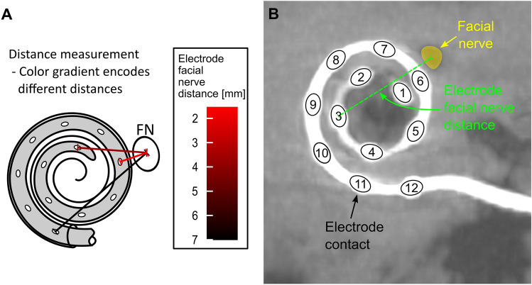
For control of the insertion flat panel volume computed tomography (fpVCT) scans were performed on an angiographic system (Axiom Artis; Siemens Healthcare AG, Erlangen, Germany) with commercially available software Syngo DynaCT (Siemens Healthcare AG) resulting in a slice thickness of 466 µm. Subsequently, secondary reconstructions (fpVCTSECO) with a slice thickness of 99 µm were created39. All CT scans were converted to the DICOM format and imported to the open-source medical image viewer Horos (Version 3.3.5; Nimble Co LLC d/b/a Purview, Annapolis, Maryland USA). First, the “cochlear view”40 was set, which is an axial view of the cochlea generated by rotation against the three body axes. In this two-dimensional view, the electrode facial nerve distance (EFND) for each electrode was measured between the center of the metal artifact and the center of the facial nerve canal in cross section. Figure 3A is a schematic illustration of the EFND measurement. Figure 3B is an example of an fpVCTSECO scan in cochlear view depicting the CI electrode contacts with their position on the array, the facial nerve, and the EFND of electrode contact number 3.
Figure 3.
(A) Schematic illustration of the measurement of the electrode facial nerve distance with color-coding of the relative distances (red: shortest distance; black: longest distance). (B) Example of the measurement of the electrode facial nerve distance in the cochlear view of an fpVCTSECO scan. The electrode contacts of the CI are numbered in order from apical to basal. The facial nerve canal is marked in yellow in the scan. The dashed green line symbolizes the distance between the center of the facial nerve and the electrode contact number 3.
Statistics
The data were analyzed with the programming language for statistical computing R (version 4.0.2) and the RStudio (version 1.3.1073) integrated developments environment. The ggplot2 package (3.3.5) was used for graphical representation of the data. In order to investigate the correlation between EFNDs and normalized EMG amplitudes, the nonparametric Spearman’s rank correlation was calculated using the stats package (4.0.2).
Results
Measurement of the electrode facial nerve distance
As can be seen in Figure 4, fpVCTSECO of subjects implanted with the electrode type Standard, FLEXsoft, or FLEX28 showed the shortest EFND for the medial electrode contact number 6. The shortest EFND of S8 and S9, both implanted with the short electrode type FLEX24, was measured for electrode contact number 3 and 4, respectively.
Figure 4.
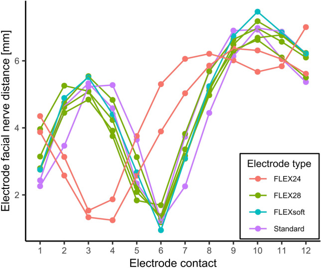
Electrode facial nerve distance as function of the electrode contact number. Distances were measured from fpVCTSECO scans in cochlear view. Colors correspond to different implanted electrode types.
Real-time insertion of the electrode
During insertion, a subject-specific current level was used to stimulate the EMG response. The current level used for the respective subject can be found in the second column of Table 3. The third column of Table 3 contains the corresponding charge level in charge units (QU), with 1 QU approximately corresponding to 1 nC.
Table 3.
Stimulation levels used for evoking EMG responses during both measurement procedures.
| Subject | Current level used during electrode insertion [CU] | Charge level used during electrode insertion [QU] | Current level used for the post insertion measurement [CU] | Charge level used for the post insertion measurement [QU] |
|---|---|---|---|---|
| S1 | 614.25 | 92.138 | 519.753 | 77.963 |
| S2 | – | – | 1134 | 170.1 |
| S3 | 378 | 56.7 | 378 | 56.7 |
| S4 | 472.5 | 70.875 | 661.5 | 99.225 |
| S5 | 472.5 | 70.875 | 311.85 | 46.778 |
| S6 | 472.5 | 70.875 | 519.75 | 77.963 |
| S7 | 378 | 56.7 | 378 | 56.7 |
| S8 | 425.25 | 63.788 | 425.25 | 63.788 |
| S9 | 378 | 56.7 | 330.75 | 49.613 |
Column 2 and 4 contain the current levels used for the real-time measurement and the post insertion measurement, respectively. Column 3 and 5 contain the corresponding charge levels for columns 2 and 4.
In 8 of the 9 subjects, an EMG response was continuously recorded on both channels during the stepwise insertion of the electrode. S2 was excluded from the analysis because no EMG response could be evoked until a number of 6 contacts had been inserted and thus no conclusion could be drawn about half of the insertion process. In subject S1, recording began when 4 contacts had already been inserted instead of two. The charge levels used during insertion ranged between a minimum of 56.7 QU and a maximum of 92.138 QU with a mean value of 67.331 QU.
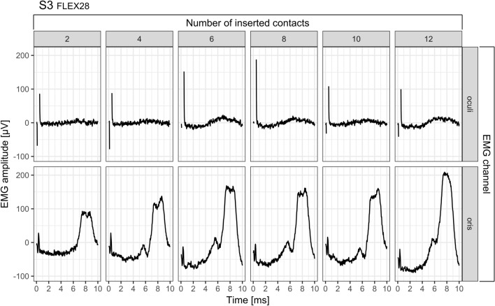
As an example, Figure 5 depicts the raw EMG recordings during the stepwise insertion process in subject S3. The upper and the lower row show the EMG curves for the periocular and perioral EMG channel respectively. The number of the currently inserted channels is indicated by the number above each graph. The curves shown are the mean value of the EMG signals evoked by the two subsequent stimulation pulses. The electrical stimulation artifact caused by the stimulation pulse can be seen at the beginning of each recording. In the case of the periocular EMG channel, the artifact is several times the amplitude of the artifact of the perioral EMG channel and is clipped because of the chosen y-axis scaling. The comparison of the amplitude of the EMG responses between the two channels clearly shows that the response strength recorded with the perioral channel was a multiple of the amplitude in the periocular channel. In the course of the stepwise insertion in subject S3, it can be seen how the EMG amplitudes in both channels increase with each step until a number of 6 electrode contacts have been inserted. As the insertion of 8 and 10 electrode contacts progresses, the EMG response decreases again, but increases a second time at complete insertion of 12 electrode contacts. In the case of the periocular canal, the EMG response reaches its maximum at 6 inserted electrode contacts; in the case of the perioral canal, the maximum is reached only at complete insertion.
Figure 5.
Example of a raw EMG recording during electrode insertion in subject S3. For each insertion step, the stimulation current level was 378 CU. The upper row shows the EMG recordings of M. orbicularis oculi, the lower row of M. orbicularis oris. The number of currently inserted contacts can be read from the number line above the graph. Each signal corresponds to the average of the EMG responses to two subsequently emitted stimulation pulses. In both EMG channels, the electrical stimulation artifact caused by the stimulation pulse can be seen at the beginning of each recording. In the case of the orbicularis oculi muscle, the artifact is several times the amplitude of the artifact of the orbicularis muscle and is therefore clipped in this representation.
EMG response strength differed greatly between subjects as well as between the periocular and perioral EMG channels. Thus, to achieve better comparability of the results, the data of each subject and each EMG channel were normalized. The normalization process assigned the value 0 to the lowest EMG response and 1 to the maximum EMG response.
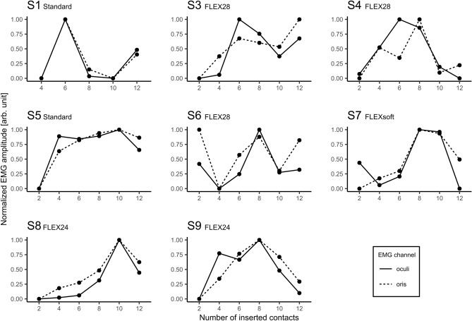
Figure 6 shows the normalized EMG response during the stepwise insertion for both EMG channels. With few exceptions, the measurements of both EMG channels demonstrated a stable concordance for all of the 8 subjects, an initial increase and subsequent decrease in the normalized EMG response can be seen as the insertion progressed.
Figure 6.
Normalized EMG responses during the stepwise electrode insertion in 8 subjects. The EMG responses are shown as function of the number of inserted electrode contacts. The solid and dashed lines correspond to the periocular and perioral EMG channel, respectively. Normalization assigned the value 0 to the lowest amplitude and 1 to the maximum amplitude.
Figure 6 shows that in the cases of S1, S3, and S6 the EMG response increases again towards the end, that is, when the array was fully inserted. The measurements in S4 demonstrated peaks of the EMG signal at two different numbers of inserted contacts (periocular: 6; perioral: 8). For the remaining subjects, the peaks appearing at the medial portion of the cochlea revealed a stable concordance between both EMG channels. Under the condition of an exactly constant step size during insertion, it can be assumed that the position P of the stimulating apical contact can be calculated as the difference between the number of all contacts on the array (all MED-EL electrode types feature 12 contacts) and the number of already inserted contacts Ninserted. During the stepwise insertion, the EMG amplitude could be continuously tracked in 8 out of 9 subjects.
| 1 |
Taking into account the deflection of the EMG signal in respect to P, the contact that is closest to the facial nerve after full insertion can now be estimated. Table 4 lists the values of P calculated by formula 1 which show the highest EMG response in each channel and compares them with the respective shortest measured EFND. The comparison revealed a clear concordance between imaging and EMG measurement in 5 of 7 (EMG periocular) and 4 of 7 (EMG perioral) subjects. With respect to S8, contact 3 shows the shortest EFND. Since step sizes of 2 contacts were used during insertion, an exact agreement cannot be determined for odd contact numbers. However, at S8 the peak at the neighboring contact 2 is visible.
Table 4.
Comparison between the shortest radiologically measured EFND per subject and the estimated position of the contact showing a clear peak in both EMG channels during insertion.
| Subject | Shortest EFND |
Poculi | Poris |
|---|---|---|---|
| S1 | 6 | 6 | 6 |
| S3 | 6 | 6 | 6 |
| S4 | 6 | 6 | 4 |
| S5 | 6 | 2 | 2 |
| S6 | 6 | 6 | 6 |
| S7 | 6 | 4 | 4 |
| S8 | 3 | 2 | 2 |
| S9 | 4 | 4 | 4 |
Post insertion measurements
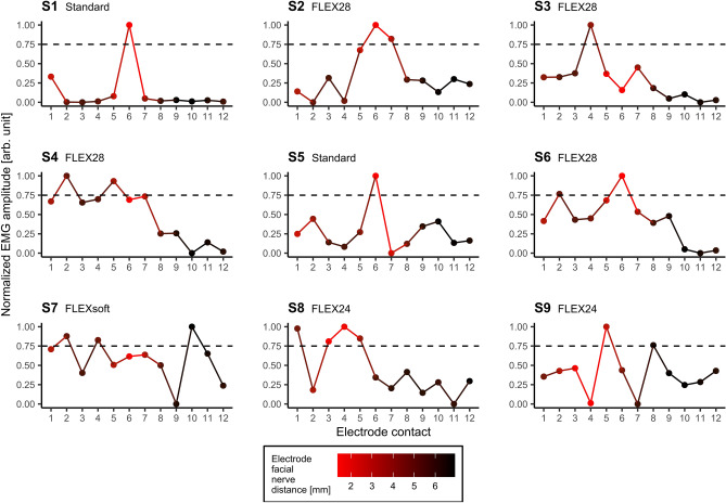
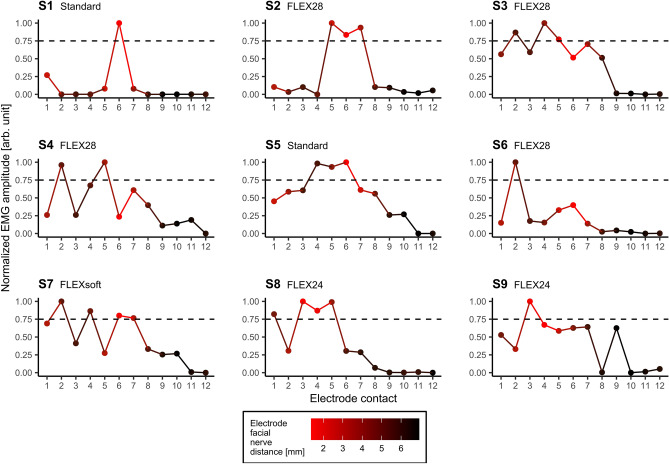
The current levels used for the post insertion measurements varied from the current levels used during the real-time measurements. Column 4 and 5 of Table 3 show the subject-specific current levels and the corresponding charge levels, respectively. Each subject showed an individual stimulation threshold, above which a visually clearly detectable EMG response could be observed. The charge levels used during insertion ranged between a minimum of 46.778 QU and a maximum of 170.1 QU with a mean value of 77.648 QU. However, too high stimulation levels could result in no clear peaks depending on the electrode contact used. Such a “breakdown” consequently caused strong EMG responses on several contacts of the array, which prevent estimations of the position of the electrode with respect to the facial nerve by means of the EMG amplitudes. Therefore, only those data were included in the analysis, which were recorded using stimulation amplitudes that elicited a clear EMG response and allowed the best possible spatial differentiation. EMG responses of the M. orbicularis oculi are depicted in Figure 7, those of the M. orbicularis oris in Figure 8 after stimulation from every contact of the fully inserted electrode array for each of the 9 subjects. As an additional dimension, the radiologically measured EFNDs per contact of the respective subject were plotted as a relative color gradient to the curves in Figures 7 and 8. As for the real-time measurements, the EMG response of each subject and each EMG channel was normalized for better comparability. Normalization assigned the value 0 to the lowest EMG response and 1 to the highest. As evaluation criterion for the presence of a spike in EMG data, a threshold at 75% normalized EMG response was arbitrarily defined. As can be seen in Figures 7 and 8, the selected current levels on single and multiple electrode contacts, respectively, achieved response strengths that exceeded 75% normalized EMG amplitude. The EMG responses that exceeded the threshold are subsequently referred to as peaks. Table 5 summarizes at which electrode contact the shortest EFND was measured radiologically, and at which contacts EMG peaks were measured after complete insertion.
Figure 7.
Normalized EMG responses of the M. orbicularis oculi as function of the contacts on the fully inserted electrode array. The color gradient depicts the radiologically determined electrode facial nerve distance (red: shortest distance; black: longest distance) for each subject. The horizontal dashed line indicates the arbitrarily chosen EMG threshold at 75% normalized EMG response.
Figure 8.
Normalized EMG responses of the M. orbicularis oris as function of the contacts on the fully inserted electrode array. The color gradient depicts the radiologically determined electrode facial nerve distance (red: shortest distance; black: longest distance) for each subject. The horizontal dashed line indicates the arbitrarily chosen EMG threshold at 75% normalized EMG response.
Table 5.
Listing of electrode contacts per subject with the shortest electrode facial nerve distance (EFND) and EMG peaks in the periocular and perioral EMG channels, which exceeded the threshold at 75% normalized EMG amplitude.
| Subject | Shortest EFND [electrode contact] |
Peaks periocular [electrode contact] |
Peaks perioral [electrode contact] |
|---|---|---|---|
| S1 | 6 | 6 | 6 |
| S2 | 6 | 6, 7 | 5, 6, 7 |
| S3 | 6 | 4 | 2, 4, 5 |
| S4 | 6 | 2, 5 | 2, 5 |
| S5 | 6 | 6 | 4, 5, 6 |
| S6 | 6 | 6 | 2 |
| S7 | 6 | 2, 4, 10 | 2, 4, 6, 7 |
| S8 | 3 | 1, 3, 4, 5 | 1, 3, 4, 5 |
| S9 | 4 | 5 | 3 |
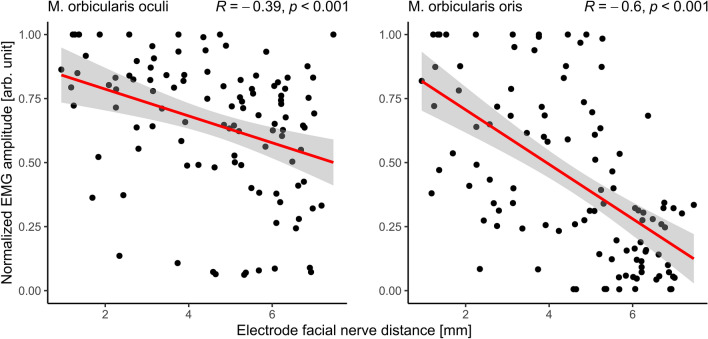
The scatter plots in Figure 9 show the relationship between the postoperatively determined EFND and the normalized amplitudes of the EMG responses of the orbicularis oculi (left side) and oris (right side) muscles measured for each electrode contact of all subjects after full insertion. The linear regression function of the data (red solid line) and the corresponding confidence interval (95%) show a clear decrease in normalized EMG responses with increasing EFND in both muscle groups. The Spearman's rank correlation coefficient R revealed a negative moderate correlation for the periocular EMG channel (R(106) = − 0.39, p < 0.001) and a negative strong correlation for the perioral EMG channel (R(106) = − 0.6, p < 0.001). Both correlations were statistically significant.
Figure 9.
Correlation between the normalized EMG responses of the M. orbicularis oculi (left side) and oris (right side) after full insertion in all subjects and the radiologically measured electrode facial nerve distances. The red line indicates the linear regression of the respective results, the gray shaded area around the regression line indicates the 0.95 confidence interval. R is the Spearman's correlation coefficient and p is the significance level of the correlation.
Discussion
In the present study, it was investigated whether the FNS evoked by electrical stimulation via the CI electrode can be used as a marker of the intracochlear position of the electrode array during and after insertion. It was hypothesized that electrode contacts with shorter distance to the facial nerve (EFND) can stimulate the nerve more effectively than contacts further away. The first part of this study included recordings of EMG responses during stepwise insertion of CI electrode arrays. The step size was two contacts at a time. After each step, stimulation pulses were emitted from the most apical contact on the array and the evoked EMG responses of the orbicularis oculi and oris muscles were recorded. In the second part of the study, stimulation pulses were sequentially emitted from each contact on the fully inserted electrode array and the evoked EMG responses were recorded. EFNDs of each patient were measured in postoperative fpVCTSECO scans and compared with the intraoperatively recorded EMG responses.
The measurements of the EFND in the “cochlear view” of fpVCTSECO scans showed sufficient feasibility. Interestingly, two types of slopes could be distinguished based on their minima, that is, the shortest EFND (Figure 4). One slope type showed the shortest EFND at contact 3 or 4, and only included the shortest electrode type (FLEX24). This electrode type was implanted in cases, in which the residual hearing should be preserved. Accordingly, the electrode should only partially cover the cochlear length to replace damaged inner hair cells in the range of the high frequencies, while keeping more apical hair cells functional. Therefore, the contacts closer to the apical end of the electrode were nearest to the facial nerve.
The other type of slope showed the shortest EFNDs at contact 6 and included all electrode types used for a full cochlear coverage (FLEX28, FLEXsoft, and Standard). The fact that the shortest EFND was measured at contact 6 for each of the three electrode types despite the difference in length between FLEX28 and FLEXsoft or Standard (see Table 2) can be explained by the fact that FLEXsoft and Standard were implanted in cochleae with longer CDL and both types have longer distances between contacts than the FLEX28.
In addition, the difference in length from the basal contact to contact 6 between the 28 mm and the 31.5 mm electrodes is relatively short (1.5 mm (5 × 0.3 mm)) and smaller than the distance between the contacts (2.1 or 2.4 mm). Consequently, the difference might not be large enough, that another contact other than number 6 will be closer to the facial nerve and though has a lower EFND. This knowledge might be used for further development and research. If further measurements of EFNDs confirm the present result, that electrode 6 has always the lowest EFND in cases of full cochlear coverage by long electrode types this can possibly be used to check correct insertion of the respected array in clinical routine by only measuring the EMG signal after insertion. In cases with partial cochlear coverage (e.g., for electro-acoustic stimulation) it might be possible to preoperatively determine, which contact should have the smallest EFND and though this contact should than be implanted closest to the facial nerve with consideration of the EMG signal.
In 8 of 9 patients, an electrically evoked EMG signal was successfully monitored during CI array insertion. As the insertion depth progressed, the distance between the most apical contact and the facial nerve initially decreased and the stimulation efficacy increased. This could be observed by the rise in EMG amplitudes as function of the number of inserted contacts. Thereafter, as insertion depth progressed, the distance between the electrode and the facial nerve increased again, which was reflected in the decrease of the EMG amplitudes. After the last insertion step, 4 of the subjects showed a new increase in EMG amplitudes. This occurred exclusively in subjects implanted with longer electrode types (Standard, FLEX28) and not in the 2 patients provided with a short FLEX24. Therefore, it can be assumed that this increase was due to a second approximation of the most apical contact with the facial nerve in the second cochlear turn. In 5 out of 8 subjects, there was concordance between the estimated number of inserted contacts, which showed an EMG peak above the threshold of 75% normalized EMG amplitude and the radiologically measured EFNDs. In one subject, whose shortest EFND was measured for an odd contact number, the EMG peak appeared at one of the even neighboring contacts. These results support the hypothesis that during increasing insertion passing of the electrode tip at the area of the facial nerve can be measured electromyographically.
ECochG is another electrophysiological measurement that can be used for real-time monitoring during cochlear implantation14. Although, ECochG is usually used to monitor cochlear trauma caused by CI electrode insertion, studies in humans and animals reported of increasing signal amplitudes with increasing electrode insertion depths, which were assumed to reflect the decreasing distance to areas with residual hearing function in the cochlear apex15. The advantage of the electromyographic measurement presented in this study over ECochG as measure for insertion depth is that the facial nerve can be used as an anatomical landmark to estimate the relative location of the electrode.
After full insertion, stimulation was performed from each electrode contact and the evoked EMG responses were recorded. The EMG profiles were normalized for better comparability between each subject and the two EMG channels used. To identify electrode contacts, which exhibited EMG peaks along the array an arbitrarily chosen threshold of 75% normalized EMG amplitude was used. The electrode contacts thus identified were compared with the electrode contacts that showed the shortest EFNDs in the postoperative fpVCTSECO images.
Interestingly, the post insertion measurement showed multiple peaks of the EMG amplitude for some subjects (e.g., S7). This effect somewhat conflicts with the hypothesis and indicates that there may be more factors influencing FNS than EFND alone. Identification of these factors with the existing data is beyond the scope of this study. Theoretically, such peaks could indicate that the affected electrode contact has a lower contact resistance to tissue (i.e., impedance) than the electrode contacts with lower EMG amplitude but relatively low EFND. However, as the routine measurements of electrode impedances performed after implantation did not register higher values at these contacts, electrode impedance can be ruled out as a possible factor. Contrarily, these peaks may rather indicate paths of particularly high electrical conductivity between the respective electrode contact and the facial nerve. Hence, multiple peaks could be the result of an inconsistent distribution of electrically conductive media (e.g., perilymph) at the individual electrode contacts. Calloway et al.15 suggested that the increase in amplitudes in their ECochG measurements as the insertion depth of the electrode progressed may have also been due to a more favorable geometry with respect to the cochlear generators. Peaks or dips in the post insertion EMG amplitudes of the present study could thus also be a result of a favorable or unfavorable geometry between the individual electrode contacts and the facial nerve. However, according to the hypothesis, both EMG channels showed agreement between the shortest EFND and EMG peaks in 5 of 9 subjects (periocular: S1, S2, S5, S6, S8; perioral: S1, S2, S5, S7, S8). Besides the peaks that exceeded the threshold, the results of the post insertion measurements showed higher EMG responses for contacts lying on the more apical half of the electrode array. As observed in the data from the insertion measurements, this may reflect the decreasing EFND of those contacts, which are closer to the facial nerve within the second cochlear turn than the more basal contacts. This assumption is also supported by the statistically significant results of the correlation analysis, which showed moderate (periocular) and strong (perioral) negative correlation between the normalized EMG amplitudes and the EFNDs of each contact.
The comparison between the EMG response patterns post insertion with those during insertion shows that both procedures in some cases led to different response patterns in the same subjects (e.g., in S4). It should be noted that a direct comparison is only possible for three subjects (S3, S7 and S8), since for all other subjects both procedures were performed with different stimulation levels (see Table 3). Inaccuracies in the step size during the manually controlled stepwise insertion may also have led to biased response patterns that could not be reproduced post insertion.
The aim of this study was to prove the feasibility of the approach. The measurement presented is still under development and requires further improvements to increase precision. The following section is intended to provide starting points for future studies.
The “cochlear view” provided only EFNDs in a two-dimensional representation of the patient's anatomy. Close to the cochlea, however, the facial nerve exhibits a complex three-dimensional course. In addition, the CI array changes its position in three dimensions as it passes through the cochlear turns. The EFND measurements proposed in the present study should be considered as an estimate of the actual distance. Future studies should therefore investigate whether the EFND can be determined more precisely by considering the three-dimensional anatomy. Recent studies reported that patients with postoperative FNS had significantly lower distance and bone density between the upper basal turn of the cochlea and the labyrinthine segment of the facial nerve33,34. Therefore, besides the EFND future studies should also include parameters such as bone density, which can influence the propagation of the electric current. The stepwise insertion in the present study was performed manually. Thus, the number of contacts already inserted could only be estimated. In addition, an anatomically defined reference was missing for a precise indication of the length of the already inserted electrode array. The threshold 75% normalized EMG amplitude was chosen arbitrarily and is only a rough method to detect peaks. Modern methods of peak detection could achieve a better differentiation of different peaks (contact in close proximity to facial nerve, most apical contact in second cochlear turn). Future studies should consider changes to the stimulation paradigm that allow a higher number of repetitions which cause less fatigue to the facial nerve and the muscles innervated by it. This should improve the signal-to-noise ratio and additionally reduce the influence of outliers (electrical artifacts from the operating room, spontaneous movements of the patient) on peak detection. The used higher stimulation amplitudes resulted in broader electric fields in the cochlea and its surrounding anatomical structures, which might have influenced the accuracy of the system. Measurements in the orbicularis oris muscle yielded EMG responses with higher amplitudes, which resulted in a better signal-to-noise ratio. Therefore, compared with measurements in the orbicularis oculi muscle, lower current levels can be applied to stimulation, which should result in better spatial resolution of the EMG. Therefore, the authors suggest future studies to focus on EMG measurements in the orbicularis oris muscle.
Conclusion
To the best of our knowledge, this is the first study to demonstrate the potential of using intentional FNS for real-time monitoring of the insertion status during and after cochlear implantation. This system might be helpful to the field of cochlear implantation, since by applying FNS stimulation, the position of the electrode can be determined quite precisely for at least the first six implanted contacts in the basal turn, which equals about 200 degrees of the cochlea. Because there is evidence that the EMG signal rises again as the stimulating contact approaches the facial nerve in the mid turn at about 540 degrees, this method could hypothetically detect an electrode tip-fold over as well. The system can easily be used to perform further measurements after surgery and during all wearing-time of the implant. After wound closure, the system can control, if manipulations during suturing of the periosteum, the subcutaneous tissue, and the skin might have led to an electrode displacement. In addition, if there is a suspicion for electrode extrusion after surgery, a measurement of the evoked EMG can be performed again. If the electrode has not been displaced, the highest EMG responses should be measured at the same stimulating contact as before.
On the long term, the system might be used in a radiation free cochlear implantation. Omitting radiation is of high benefit, especially for children41, since there is growing evidence from epidemiological studies that radiation exposure of the brain poses further substantial risks42–44. In this concept preoperative planning of the implantation, like measuring the CDL45,46, the examination of the course of facial nerve47 and the size of the temporal bone48, will be performed in MRI imaging. For intra- and postoperative control the presented system, may be used in combination with ECochG49 or electrically evoked compound action potentials18. If required, after the waiting time defined by the manufacturer, an MRI scan could be performed with special protocols to investigate the electrode position21.
Acknowledgements
The authors thank the CI recipients for their participation and the team of the Comprehensive Hearing Center at the University of Wuerzburg for the extensive help.
Abbreviations
- CDL
Cochlear duct length
- CI
Cochlear implant
- ECochG
Electrocochleography
- EFND
Electrode facial nerve distance
- EMG
Electromyography
- FNM
Facial nerve monitoring
- FNS
Facial nerve stimulation
- fpVCT
Flat-panel volume computer tomography
- MRI
Magnet resonance imaging
- RIB2
Research interface box 2
Author contributions
K.R. and D.P.H. conceived and designed the project. R.H. and K.R. supervised the study. A.K. preselected suitable patients for participation in the study. K.R. and S.K. performed CI surgery. D.P.H. built the EMG recording setup with support from M.C. and conducted the intraoperative EMG measurements. T.N. performed medical imaging (fpVCT) and supported F.T.M.G. and D.P.H. in secondary reconstructions of fpVCT scans. D.P.H. evaluated the fpVCTSECO and EMG data and performed the analysis including figures and statistics. D.P.H. and K.R. wrote the manuscript. All authors reviewed the manuscript.
Funding
This publication was supported by the Open Access Publication Fund of the University of Wuerzburg. Open Access funding enabled and organized by Projekt DEAL.
Competing interests
The authors declare no competing interests.
Footnotes
Publisher's note
Springer Nature remains neutral with regard to jurisdictional claims in published maps and institutional affiliations.
References
- 1.Lenarz T. Cochlear implant—State of the art. Laryngo-Rhino-Otol. 2017;96:S123–S151. doi: 10.1055/s-0043-101812. [DOI] [PubMed] [Google Scholar]
- 2.Dhanasingh A, Jolly C. Review on cochlear implant electrode array tip fold-over and scalar deviation. J. Otol. 2019;14:94–100. doi: 10.1016/j.joto.2019.01.002. [DOI] [PMC free article] [PubMed] [Google Scholar]
- 3.Widmann G, Dejaco D, Luger A, Schmutzhard J. Pre- and post-operative imaging of cochlear implants: A pictorial review. Insights Imaging. 2020;11:93. doi: 10.1186/s13244-020-00902-6. [DOI] [PMC free article] [PubMed] [Google Scholar]
- 4.Ishiyama A, Risi F, Boyd P. Potential insertion complications with cochlear implant electrodes. Cochlear Implants Int. 2020;21:206–219. doi: 10.1080/14670100.2020.1730066. [DOI] [PubMed] [Google Scholar]
- 5.Büchner A, Illg A, Majdani O, Lenarz T. Investigation of the effect of cochlear implant electrode length on speech comprehension in quiet and noise compared with the results with users of electro-acoustic-stimulation, a retrospective analysis. PLoS ONE. 2017;12:e0174900. doi: 10.1371/journal.pone.0174900. [DOI] [PMC free article] [PubMed] [Google Scholar]
- 6.Jiam NT, Pearl MS, Carver C, Limb CJ. Flat-panel CT imaging for individualized pitch mapping in cochlear implant users. Otol. Neurotol. 2016;37:672–679. doi: 10.1097/MAO.0000000000001060. [DOI] [PubMed] [Google Scholar]
- 7.Jiam NT, et al. Association between flat-panel computed tomographic imaging-guided place-pitch mapping and speech and pitch perception in cochlear implant users. JAMA Otolaryngol. Neck Surg. 2019;145:109–116. doi: 10.1001/jamaoto.2018.3096. [DOI] [PMC free article] [PubMed] [Google Scholar]
- 8.O’Connell BP, et al. Electrode location and angular insertion depth are predictors of audiologic outcomes in cochlear implantation. Otol. Neurotol. 2016;37:1016–1023. doi: 10.1097/MAO.0000000000001125. [DOI] [PMC free article] [PubMed] [Google Scholar]
- 9.O’Connell BP, et al. Insertion depth impacts speech perception and hearing preservation for lateral wall electrodes. Laryngoscope. 2017;127:2352–2357. doi: 10.1002/lary.26467. [DOI] [PMC free article] [PubMed] [Google Scholar]
- 10.Rak K, et al. Influence of cochlear parameters on the current practice in cochlear implantation. HNO. 2021;69:24–30. doi: 10.1007/s00106-020-00969-z. [DOI] [PubMed] [Google Scholar]
- 11.Aschendorff A. Imaging bei cochlear-implant-patienten. Laryngo-Rhino-Otol. 2011;90:S16–S21. doi: 10.1055/s-0030-1270448. [DOI] [PubMed] [Google Scholar]
- 12.Carelsen B, et al. Cochlear implant electrode array insertion monitoring with intra-operative 3D rotational X-ray. Clin. Otolaryngol. 2007;32:46–50. doi: 10.1111/j.1365-2273.2007.01319.x. [DOI] [PubMed] [Google Scholar]
- 13.Perazzini C, et al. Fluoroscopy guided electrode-array insertion for cochlear implantation with straight electrode-arrays: A valuable tool in most cases. Eur. Arch. Otorhinolaryngol. 2021;278:965–975. doi: 10.1007/s00405-020-06151-z. [DOI] [PubMed] [Google Scholar]
- 14.Barnes JH, Yin LX, Saoji AA, Carlson ML. Electrocochleography in cochlear implantation: Development, applications, and future directions. World J. Otorhinolaryngol. Head Neck Surg. 2021;7:94–100. doi: 10.1016/j.wjorl.2020.04.006. [DOI] [PMC free article] [PubMed] [Google Scholar]
- 15.Calloway NH, et al. Intracochlear electrocochleography during cochlear implantation. Otol. Neurotol. 2014;35:1451–1457. doi: 10.1097/MAO.0000000000000451. [DOI] [PubMed] [Google Scholar]
- 16.Harris MS, et al. Patterns seen during electrode insertion using intracochlear electrocochleography obtained directly through a cochlear implant. Otol. Neurotol. 2017;38:1415–1420. doi: 10.1097/MAO.0000000000001559. [DOI] [PMC free article] [PubMed] [Google Scholar]
- 17.Mittmann P, Ernst A, Todt I. Intraoperative electrophysiologic variations caused by the scalar position of cochlear implant electrodes. Otol. Neurotol. 2015;36:1010–1014. doi: 10.1097/MAO.0000000000000736. [DOI] [PubMed] [Google Scholar]
- 18.Mittmann P, et al. Electrophysiological detection of electrode fold-over in perimodiolar cochlear implant electrode arrays: A multi-center study case series. Eur. Arch. Otorhinolaryngol. 2020;277:31–35. doi: 10.1007/s00405-019-05653-9. [DOI] [PubMed] [Google Scholar]
- 19.Di Lella FA, De Marco D, Fernández F, Parreño M, Boccio CM. In vivo real-time remote cochlear implant capacitive impedance measurements: A glimpse into the implanted inner ear. Otol. Neurotol. 2019;40:S18. doi: 10.1097/MAO.0000000000002214. [DOI] [PubMed] [Google Scholar]
- 20.Grolman W, et al. Spread of excitation measurements for the detection of electrode array foldovers: A prospective study comparing 3-dimensional rotational X-ray and intraoperative spread of excitation measurements. Otol. Neurotol. 2009;30:27–33. doi: 10.1097/MAO.0b013e31818f57ab. [DOI] [PubMed] [Google Scholar]
- 21.Stratmann A, et al. MRI-based estimation of scalar cochlear-implant electrode position. BioMed Res. Int. 2017;2017:e6372704. doi: 10.1155/2017/6372704. [DOI] [PMC free article] [PubMed] [Google Scholar]
- 22.Prell J, Strauss C, Plontke SK, Rampp S. Intraoperative monitoring of the facial nerve: Vestibular schwannoma surgery. HNO. 2017;65:404–412. doi: 10.1007/s00106-017-0340-1. [DOI] [PubMed] [Google Scholar]
- 23.Casano K, et al. Additional benefits of facial nerve monitoring during otologic surgery. Otolaryngol. Neck Surg. 2020;163:572–576. doi: 10.1177/0194599820915458. [DOI] [PubMed] [Google Scholar]
- 24.Gidley PW, et al. Contemporary opinions on intraoperative facial nerve monitoring. OTO Open. 2018;2:2473974X18791803. doi: 10.1177/2473974X18791803. [DOI] [PMC free article] [PubMed] [Google Scholar]
- 25.Guntinas-Lichius O, Eisele DW. Facial nerve monitoring. Salivary Gland Neoplasms. 2016;78:46–52. doi: 10.1159/000442124. [DOI] [PubMed] [Google Scholar]
- 26.Hsieh H-S, Wu C-M, Zhuo M-Y, Yang C-H, Hwang C-F. Intraoperative facial nerve monitoring during cochlear implant surgery. Medicine (Baltimore) 2015;94:e456. doi: 10.1097/MD.0000000000000456. [DOI] [PMC free article] [PubMed] [Google Scholar]
- 27.Mandour MF, Khalifa MA, Khalifa HMA, Amer MAR. Iatrogenic facial nerve exposure in cochlear implant surgery: Incidence and clinical significance in the absence of intra-operative nerve monitoring. Cochlear Implants Int. 2019;20:250–254. doi: 10.1080/14670100.2019.1625126. [DOI] [PubMed] [Google Scholar]
- 28.Ansó J, et al. A neuromonitoring approach to facial nerve preservation during image-guided robotic cochlear implantation. Otol. Neurotol. 2016;37:89–98. doi: 10.1097/MAO.0000000000000914. [DOI] [PubMed] [Google Scholar]
- 29.Berrettini S, de Vito A, Bruschini L, Passetti S, Forli F. Facial nerve stimulation after cochlear implantation: Our experience. Acta Otorhinolaryngol Ital. 2011;31:11–16. [PMC free article] [PubMed] [Google Scholar]
- 30.Gold SR, Vicki M, Kamerer DB, Koconis CA. Fluoride treatment for facial nerve stimulation caused by cochlear implants in otosclerosis. Otolaryngol. Neck Surg. 1998;119:521–523. doi: 10.1016/S0194-5998(98)70116-0. [DOI] [PubMed] [Google Scholar]
- 31.Muckle RP, Levine SC. Facial nerve stimulation produced by cochlear implants in patients with cochlear otosclerosis. Am. J. Otol. 1994;15:394–398. [PubMed] [Google Scholar]
- 32.Kamogashira T, et al. Prediction of intraoperative CSF gusher and postoperative facial nerve stimulation in patients with cochleovestibular malformations undergoing cochlear implantation surgery. Otol. Neurotol. 2017;38:e114. doi: 10.1097/MAO.0000000000001440. [DOI] [PubMed] [Google Scholar]
- 33.Aljazeeri IA, Khurayzi T, Al-Amro M, Alzhrani F, Alsanosi A. Evaluation of computed tomography parameters in patients with facial nerve stimulation post-cochlear implantation. Eur. Arch. Otorhinolaryngol. 2020 doi: 10.1007/s00405-020-06486-7. [DOI] [PubMed] [Google Scholar]
- 34.Hatch JL, et al. Can preoperative CT scans be used to predict facial nerve stimulation following CI? Otol. Neurotol. 2017;38:1112–1117. doi: 10.1097/MAO.0000000000001497. [DOI] [PMC free article] [PubMed] [Google Scholar]
- 35.Frijns JHM, Kalkman RK, Briaire JJ. Stimulation of the facial nerve by intracochlear electrodes in otosclerosis: A computer modeling study. Otol. Neurotol. 2009;30:1168–1174. doi: 10.1097/MAO.0b013e3181b12115. [DOI] [PubMed] [Google Scholar]
- 36.Bahmer A, Adel Y, Baumann U. Preventing facial nerve stimulation by triphasic pulse stimulation in cochlear implant users: Intraoperative recordings. Otol. Neurotol. 2017;38:e438–e444. doi: 10.1097/MAO.0000000000001603. [DOI] [PubMed] [Google Scholar]
- 37.Bahmer A, Baumann U. The underlying mechanism of preventing facial nerve stimulation by triphasic pulse stimulation in cochlear implant users assessed with objective measure. Otol. Neurotol. 2016;37:1231–1237. doi: 10.1097/MAO.0000000000001156. [DOI] [PubMed] [Google Scholar]
- 38.Sefien I, Hamada S. Facial nerve stimulation as a complication of cochlear implantation. Indian J. Otolaryngol. Head Neck Surg. 2019;71:474–479. doi: 10.1007/s12070-019-01649-3. [DOI] [PMC free article] [PubMed] [Google Scholar]
- 39.Pearl MS, Roy A, Limb CJ. High-resolution secondary reconstructions with the use of flat panel CT in the clinical assessment of patients with cochlear implants. Am. J. Neuroradiol. 2014;35:1202–1208. doi: 10.3174/ajnr.A3814. [DOI] [PMC free article] [PubMed] [Google Scholar]
- 40.Xu J, Xu S-A, Cohen LT, Clark GM. Cochlear view: Postoperative radiography for cochlear implantation. Otol. Neurotol. 2000;21:49–56. [PubMed] [Google Scholar]
- 41.Ehrmann-Müller D, et al. Cochlear implantation in children without preoperative computed tomography diagnostics. Analysis of procedure and rate of complications. Int. J. Pediatr. Otorhinolaryngol. 2020;138:110266. doi: 10.1016/j.ijporl.2020.110266. [DOI] [PubMed] [Google Scholar]
- 42.Journy N, et al. Predicted cancer risks induced by computed tomography examinations during childhood, by a quantitative risk assessment approach. Radiat. Environ. Biophys. 2014;53:39–54. doi: 10.1007/s00411-013-0491-8. [DOI] [PubMed] [Google Scholar]
- 43.Miglioretti DL, et al. The use of computed tomography in pediatrics and the associated radiation exposure and estimated cancer risk. JAMA Pediatr. 2013;167:700–707. doi: 10.1001/jamapediatrics.2013.311. [DOI] [PMC free article] [PubMed] [Google Scholar]
- 44.Pearce MS, et al. Radiation exposure from CT scans in childhood and subsequent risk of leukaemia and brain tumours: A retrospective cohort study. Lancet. 2012;380:499–505. doi: 10.1016/S0140-6736(12)60815-0. [DOI] [PMC free article] [PubMed] [Google Scholar]
- 45.George-Jones NA, Tolisano AM, Kutz JWJ, Isaacson B, Hunter JB. Comparing cochlear duct lengths between CT and MR images using an otological surgical planning software. Otol. Neurotol. 2020;41:e1118. doi: 10.1097/MAO.0000000000002777. [DOI] [PubMed] [Google Scholar]
- 46.Nash R, Otero S, Lavy J. Use of MRI to determine cochlear duct length in patients undergoing cochlear implantation. Cochlear Implants Int. 2019;20:57–61. doi: 10.1080/14670100.2018.1549186. [DOI] [PubMed] [Google Scholar]
- 47.Haneda J, Ishikawa K, Okamoto K. Better continuity of the facial nerve demonstrated in the temporal bone on three-dimensional T1-weighted imaging with volume isotropic turbo spin echo acquisition than that with fast field echo at 3.0 tesla MRI. J. Med. Imaging Radiat. Oncol. 2019;63:745–750. doi: 10.1111/1754-9485.12962. [DOI] [PubMed] [Google Scholar]
- 48.Fruauff K, Coffey K, Chazen JL, Phillips CD. Temporal bone imaging. Top. Magn. Reson. Imaging. 2015;24:39–55. doi: 10.1097/RMR.0000000000000044. [DOI] [PubMed] [Google Scholar]
- 49.Radeloff A, et al. Intraoperative monitoring using cochlear microphonics in cochlear implant patients with residual hearing. Otol. Neurotol. 2012;33:348–354. doi: 10.1097/MAO.0b013e318248ea86. [DOI] [PubMed] [Google Scholar]


