

Abstract
Bone defects, with second highest demand for surgeries around the globe, may lead to serious health issues and negatively influence patient lives. The advances in biomedical engineering and sciences have led to the development of several creative solutions for bone defect treatment. This review provides a brief summary of bone graft materials, an organized overview of top-down and bottom-up (bio)manufacturing approaches, plus a critical comparison between advantages and limitations of each method. We specifically discuss additive manufacturing techniques and their operation mechanisms in detail. Next, we review the hybrid methods and promising future directions for bone grafting, while giving a comprehensive US-FDA regulatory science perspective, biocompatibility concepts and assessments, and clinical considerations to translate a technology from a research laboratory to the market. The topics covered in this review could potentially fuel future research efforts in bone tissue engineering, and perhaps could also provide novel insights for other tissue engineering applications.
Keywords: FDA regulatory science, bone defect, bone graft, biomanufacturing
Graphical Abstract

1. Introduction
With a global prevalence of more than two million graft procedures per year, bone grafts are one of the most common transplants [1][2][3][4][5]. Small bone defects can be restored naturally, while large defects created by severe trauma, accidents, or tissue resection are unable to heal on their own [6].
As a rigid organ in humans and live animals, bone supports and protects different organs, tissues and facilitates the mobility of the body [7][8]. These unique applications of bone are mainly attributed to the hierarchical architecture of bone, which is mainly consists of the soft collagen protein and stiffer apatite mineral [9]. The overall stiffness of bone is primarily controlled by the natural mineral content as well as collagen to mineral ratio [7][10].
The mechanism of bone regeneration can be categorized as direct or indirect healing [11]. The size of fracture is one of the important factors that affects the bone healing mechanism. Direct bone healing mainly starts when a small and narrow (≤ 0.1 mm) fracture occurs, and the site of a fracture is rigidly stabilized. During direct bone healing, the small gap is covered directly by continuous ossification, following Haversian remodeling in a serial order [12]. In larger defect mostly heals by the indirect bone healing via various parallel events, such as blood clotting, inflammatory response, fibro-cartilage callus formation, intramembranous and endochondral ossification, and results in bone remodeling [11][12]. A critical size defect is defined as the minimum defect dimension which is incapable of repairing without intervention. Per ASTM F2721, in a critical size defect, the length of defect is at least 1.5 to 2 times the diameter of the selected bone. Critically sized defects can overwhelm the tissue regeneration capacity and lead to permanent disabilities [13][14]. Thus, surgical interventions are needed for the treatment of critically sized defects.
Bone mimetic grafts, with hierarchical structure, and effective functionality could be engineered by merging suitable biomaterials [7], cells [16], and bioactive agents [17]. To design biomimetic bone scaffolds, a combination of nano/micro-technologies with macro-technologies is required [18]. Although many technologies have been developed for bone tissue engineering incorporating many of the above-mentioned parameters, translation of such technologies into clinical applications remains a major challenge [19]. Besides the technical challenges and design consideration of a construct for treatment of critically sized bone defects, the scalability of the production method remains a hurdle for clinical translation. Therefore, standardization of fabrication protocol according to United States Food and Drug Administration (US-FDA) approval requirements, low invasiveness and cost-effectiveness are essential for translating technologies for clinical bone grafting.
Even though there is rich literature on bone biology and graft materials, most of these advancements have not yet been introduced to market and there is an urgent need for a roadmap for clinical translation of promising bone graft technologies. This review aims to fill this gap and give an organized overview of the most common (bio)manufacturing methods for bone grafting materials with a special focus on regulatory pathways and US-FDA requirements. In the beginning, we briefly review the most common bone grafting materials, and then highlight the (bio)manufacturing processes used for engineering synthetic bone grafts. Finally, a conclusive section on the regulatory pathways and processes is presented.
2. Materials for Bone Grafts
Several types of biomaterials, including (bio)ceramics, biopolymers, metals, and composites, have been investigated by researchers over the last decades for bone grafting and regeneration. The function of such grafts in bone regeneration is to provide mechanical support, filling the bone defects, enhancing the adherence and growth of cell, providing the site for extracellular cell matrix (ECM) deposition (osteoconduction), and inducing vessels and bone growth into the graft [20][21][22]. To fulfill such criteria, the graft material should exhibit some important characteristics including biocompatibility, bioactivity, osteoconductivity, osteoinductivity, and also appropriate mechanical integrity throughout the healing process, as well as optimize degradation to match the rate of ECM deposition [23]. Besides the above-mentioned, the size and shape of the graft should allow for the trafficking of cells inside the graft, diffusion of growth factors, nutrients, as well as easy excretion of by-products and waste from the tissues. Grafts can also facilitate the differentiation of progenitor cells to osteoblasts (osteoinduction) [24]. Moreover, the graft surface chemistry should facilitate ECM deposition, and provides the possibility for smart, controlled, and sustained release of biomolecules and drugs [25][26]. Hence, the selection of biomaterials is a critical aspect for graft design and application. Bone grafts could be categorized into body-derived and tissue engineered ones [21]. Body-derived bone grafts (autografts: from the same individual, isografts: from the twin of that individual, allografts: from same species, xenografts: from other species) [27], have shown great promise in clinical applications [28]. However, due to the lack of supply for such bone substitutes, the chance of diseases transmission, potential donor site morbidity, and the need for immunosuppressive drugs for cellular allografts and xenografts, the research and entrepreneurial activities have slowly shifted toward synthetic grafts [5][7][21][29]. In the next subsections, widely used graft materials will be discussed in more detail (Table 1).
Table 1:
Advantages and disadvantages of common materials for bone grafts.
| Graft Type | Advantages | Disadvantages | References |
|---|---|---|---|
| Autografts | High osteoconductive and osteogenic properties (gold standard) | Donor site complication, pain, blood loss during the harvesting process, long surgery time, infection possibility, and limited material availability |
[14][30]
[31][22] |
| Allografts | Good for patients with poor healing potential, established nonunion, and extensive comminution after fractures, modifiable | Immunogenic and more prone to failure and rejection compared to autografts, The risk of disease transmission, and limited material availability |
[27][22][32]
[33][34][35] |
| (Bio)ceramics | High biocompatibility, bone-like mechanical properties, easy preparation, and relatively low cost | High brittleness |
[21][40]
[41][42] |
| Polymers | Reasonable price, low toxicity, biocompatibility, reproducible/controllable mechanical/chemical properties, adjustable biodegradation rates | Hydrophobicity and poor wettability for most of the synthetic polymers |
[44][47]
[24][52] |
| Hydrogels | flexible, biocompatible, biodegradable, and porous | Inconsistent hydration, Inconsistent elasticity, weak mechanical properties, and burst release | [54][23] |
2.1. Human-Derived Bone Grafts
2.1.1. Autologous Bone Grafts
Autologous natural bone graft is a graft that is harvested from patients and transplanted to another site of the patient [30][31]. An autologous bone graft can integrate quickly into the host bone defeat site due to the osteoconductive and osteogenic properties, which make the autologous the gold standard in bone defect treatment and evaluation of the other bone grafts and substitutes. However, donor site complication, pain, and blood loss during the harvesting process, as well as long surgery time, the infection possibility, and limited material availability hindered the application of autologous grafts in bone regeneration [14][22].
2.1.2. Allogeneic Bone Grafts
Allogeneic bone graft is the graft that is harvested from one person and transplanted to a genetically different person (from same species) [27][22]. Allograft is an alternative replacement for autografts and has been investigated effectively in clinical conditions, particularly for patients with poor healing potential, established nonunion, and extensive comminution after fractures [27]. After harvesting the bone for allograft, the bone could be machined, customized and demineralized to make the allograft personalized and more appropriate for patients or specific case applications [22]. Cellular allografts could lead to severe immune response and can be rejected unless the host immune system is suppressed. Thus, decellularized allografts have been more attractive.
Demineralized bone matrix (DBM) is the main process of making allograft, in which the bone is treated with a mild acid to remove more than 40% of bone mineral content while the growth factor and proteins such as collagens, non-collagenous remain in the graft. The structure and integrity of DBM make it an appropriate scaffold for bone filling defect. The DBM mechanical properties depend on the mineral content of the graft after acid treatment, while its osteoinductivity is mainly correlated to the content of remnant growth factors. Allografts comparatively more available than autografts, but they are still immunogenic and more prone to failure and rejection, due to the activation of major histocompatibility complex (MHC) antigens, immune response, and activation of inflammatory cells [32][33]. Another weakness of allografts is the risk of disease transmission [14][34]. Overall, these disadvantages have called for development of alternative solutions for autografts and allografts [35].
2.2. Tissue Engineered Bone Grafts
Tissue engineering has emerged as a promising tool for development of alternative therapies replacing autografts and allografts [36] [37]. In most tissue engineered grafts, constructs made of biomaterials are used to serve as a scaffold supporting tissue regeneration. These scaffolds could also carry therapeutics that are beneficial for tissue repair. Different types of materials such as (bio)ceramics, polymers, and hydrogel have been used for bone tissue engineering in several studies due to their excellent biocompatibility, adjustable chemical composition, and biodegradation [38][39]. Each class of the mentioned synthetic materials are briefly discussed in following sections.
2.2.1. (Bio)ceramics
(Bio)ceramics are materials that specifically developed or synthesized for orthopedic (or dental) implant applications. This type of material is commonly investigated and used to replace hard tissue like bone in the body. Common (bio)ceramics used in the field of bone healing are categorized according to their behavior as follows: (a) bioresorbable such as calcium sulfate, (b) bioactive or surface-active (i.e., hydroxyapatite), (c) non-resorbable or inert such as alumina, and zirconia. Next, we briefly describe each (bio)ceramic and their advantages as well as their limitation. For example, calcium sulfate (plaster of Paris) is an osteoconductive and bioresorbable ceramics that has been investigated in bone regeneration and void filling [39]. As a disadvantage, due to the rapid resorption rate, the calcium sulfate can only be employed to fill small bone defects [21]. The easy preparation and relatively low cost have made calcium sulfate a convenient material to be combined with other synthetic bone substitutes and/or growth factors [36].
Hydroxyapatites (HA) is a naturally occurring calcium phosphate with the chemical formula of Ca10[PO4]6[OH]2 and composes about 50% of the weight of the bone, which makes it an excellent material for bone scaffold [22]. Mechanical properties of HA are close to the bone (weak mechanical properties under tension and shear), but it has high resistance under compressive loads [38]. The macro and interconnected pores of HA (pore with diameters larger than 100 μm) make it an excellent surface for cell attachment, proliferation, and osteoprogenitor cells differentiation, revascularization, and bone formation [40]. However, weak fatigue properties in bulk form are a major drawback for HA [41].
Bioactive glass or bioglass is a bioactive group of synthetic materials made of silicon dioxide (SiO2), sodium oxide (Na2O), calcium oxide (CaO), and phosphorus pentoxide (P2O5). Addition of potassium oxide (K2O), magnesium oxide (MgO), and boric oxide (B2O) leads to improved physical bonding between bioglass and the host bone [42]. The main disadvantages of (bio)ceramics over other synthetic materials is their brittleness. On the other hand, they exhibit excellent biocompatibility, offer bone-like mechanical properties and in some cases form an osteogenic environment.
2.2.2. Polymers
Polymers are a widely used class of materials for bone grafting which could be divided into two main groups: Natural polymers, and synthetic polymers. Due to the reasonable price, low toxicity, and biocompatibility, natural polymers such as collagen, fibrin, and hyaluronic acid have been studied by the researcher to be employed as grafts for bone regeneration application over decades [43]. However, recent studies grow interest to employ synthetic polymers in clinical applications due to their good mechanical strength, reproducible/controllable mechanical-chemical properties, and controllable biodegradation rates [44].
Common examples of synthetic polymers are poly(lactic-co-glycolic acid) (PLGA) [45], poly lactic acid (PLA) and their copolymers [46], polycaprolactone (PCL) [47], polydioxanone (PDO) [48], polyurethanes (PU) [49], poly ether-ether-ketone (PEEK) [50], and polyvinyl alcohol (PVA) [51]. Among synthetic polymers, PLGA and PCL based scaffolds have reached the clinic [24].
However, typically synthetic polymers suffer from hydrophobicity and poor wettability which weaken the cells attachment to them. To overcome this issue, the polymer surface treatments with various chemical and biomaterials is a common approach [44][52]. In addition, the mixing of natural protein-based polymers with synthetic materials can overcome this challenge.
2.2.3. Hydrogels
Hydrogels as porous hydrophilic polymeric network with high water content are one of the most promising materials for bone grafts [53]. Naturally derived hydrogels, such as gelatin, alginate, and chitosan, as well as some synthetic hydrogel such as polyethylene glycol (PEG), show excellent biocompatibility and have been investigated in different bone regeneration studies [54]. Most of natural hydrogels are degradable in vivo and their physical, chemical, and biological properties can be tailored by addition of other gels, polymers, proteins, peptides, and nanomaterials. The main disadvantage of the naturally derived hydrogel is their batch-to-batch variability. Synthetic hydrogels are more consistent. The weak mechanical properties is another disadvantage of hydrogels for treatment of load bearing bone defects [23].
3. (Bio)manufacturing of Bone Grafts
In the last decade, a large variety of 3D scaffold fabrication methods have been used to create bone grafts. Here, (bio)manufacturing methods for bone grafts are divided into two main groups: (1) Top-down, and (2) Bottom-up approaches. In the bone tissue engineering typically the fabrication methods are discussed as conventional (simple) versus novel (advanced) methods. However, the objective of this section is to give a more organized and comprehensive overview of all (bio)manufacturing options for bone graft fabrication. The methods’ benefits, potential limitations, and method’s product characteristics are presented. In the hybrid methods section, the compatibility of methods for being combined with other methods for future directions are discussed based on the current literature.
3.1. Top-down Approaches
The top-down approaches typically are referred to strategies in which a scaffold with desired architecture is engineered without controlling the spatial distribution of active molecules and cells[55]. The top-down approaches as a potential solution for bone defects treatment have been investigated in recent years. In this strategy, a scaffold is being engineered that mimics the mechanical and structural features of the defect. The scaffolds then can be used as synthetic grafts with or without cellularization. Top-down methods have been reviewed critically elsewhere[56][57][58], therefore, commonly used top-down methods to generate bone grafts are briefly presented here (Figure 2). In addition, the benefits and potential limitations of top-down approaches are listed later on.
Figure 2:

Top-down approaches for (bio)manufacturing of bone grafts. (A) Solvent casting, (B) Thermally induced phase separation (TIPS), (C) Sol-gel, (D) Microsphere sintering, (E) Electrospinning, (F) Pore generation methods (from top to bottom: particulate leaching, emulsification freeze-drying, gas foaming).
3.1.1. Solvent-casting of a porous structure
This method is a classical approach [59], commonly used with particulate leaching technique as the pore formation step [60][61][62]. The main advantages of such a method are its simplicity, low cost, and room temperature processing during bone graft fabrication. In this technique, either a dissolved polymer or nanocomposite (such as HA [63][64], silk [61], PLA [65], or PLGA [66]) in an organic solvent (such as chloroform or methylene chloride) cast into a mold containing solid porogen (salt crystals like sodium chloride and sodium citrate) or a supporting mold is dipped into the polymer solution [65][66]. The porogens dissolution can happen afterwards in a soaking step and the formed structures are highly porous which are sometimes called “foam” [65][66]. Parameters to control the scaffold mechanical properties and the structure are the concentration and the material of the polymer solution, polymer to salt ratio, the size, amount, and material of the porogens [67][68][49]. Despite the simplicity and effectiveness of this method to build bone implants, the lack of high control on pore size, shape, and distribution [69][70], low reproducibility [71], and limitations to completely washing out porogens and toxic solvents in thick constructs [69],are the main drawbacks of this method.
3.1.2. Thermally Induced Phase Separation (TIPS)
In this technique, changes in the thermal energy induce the separation of a homogenous polymer solution into a multi-phase system throughout a quenching step [72][73]. The organic solvent in this technique is usually phenol or naphthalene and the polymer dissolution in the solvent happens at high temperature [73]. During cooling down the system, the phase separation is triggered and leads to a polymer-rich phase and a solvent-rich phase. Then the solvent-phase is removed using different operations such as evaporation, extraction, or sublimation resulting in final porous bone scaffold. Parameters to control the final product characteristics are a type of polymer and solvent, the solution concentration, and the operation temperature [72][73][74]. The most common operation temperature and process time are reported 60°C for 2 hours [45][75]. A variety of natural and synthetic polymers including gelatin [76], chitosan [77], poly (l-lactic acid) (PLLA) [78][79], PLGA [45], PCL [80], and PU [81], have been used to fabricate porous tissue engineering scaffolds by TIPS with porosity range of 73% to 97.5% and pore size ranging from 30 nm to 420 μm. This method can be easily combined with other fabrication techniques [82]. The main advantage of TIPS is the high pore interconnection, high pore-morphology control, and scalability of the method. However, since the method is not solvent-free, risk of toxicity may limit the application of this method similar to the solvent-casting technique.
3.1.3. Sol-gel
In a sol-gel method for bone graft fabrication, a solution (a dispersion of colloidal particles in a liquid) goes through a controlled gelation mechanism to provide a very porous, highly ordered spongy-like structure incorporated with nano-scale materials and features [83][84]. This gel has discrete particles and polymers as precursors such as chlorides or metal alkoxides. During the process, these precursors are hydrolyzed and poly-condensed to form colloids. Mixing, casting, and gelation are the major steps and the product quality in this method can be adjusted by changing the concentrations [84]. There are other post-gelation steps including drying [84], chemical stabilization [84], and densification [84], which solidifies the gel and gives a mechanically robust scaffold. This method can be used for a wide variety of materials such as ceramics [85], glass [85][86], metal oxides [87], composites [88], and thin-film coatings [89]. Generally, traditional melt-derived glasses and the sol-gel process are the two approaches to form bioactive glasses [88]. Some bone tissue engineering studies attempted to optimize sol-gel-derived bioactive glass scaffolds by adding a sintering step at the end of the process [90]. The averaged porosity and pore size range from 85% to 95% and 200 μm to 1000 μm are achievable in this method [85]. The main advantages of the sol-gel method are: low-temperature operation, an unlimited variety of chemical compositions and complex organic-inorganic hybrid materials, and economic feasibility. However, being time-consuming and having low control over the porosity of the final structure are considered as the disadvantages of sol-gel scaffold fabrication.
The studies on sol-gel-derived scaffolds for bone tissue engineering is an active area of research [91][92].
3.1.4. Microsphere Sintering
This top-down method sinters ceramic/polymer composite microspheres (obtained from emulsion/solvent evaporation technique) and forms the porous 3D bone scaffolds. Comparatively the porosity of the produced scaffold is low (around 40%) and consequently stronger mechanical properties which are comparable to cancellous bone [93]. Two major process factors to adjust the product characteristics are sintering time and sintering temperature. Higher temperature and longer process time result lower porosity and better mechanical properties [94]. An alternative to raised temperature sintering is the microspheres sintering (fusion) with solvents [94][95][96].
PLGA is the most common synthetic polymer that is utilized for the fabrication of microspheres-sintered scaffolds [95][96][97][98]. One of the interesting claims about microsphere sintering is the use of CO2 for subcritical sintering which hypothetically creates interconnective pores with higher porosity compared to the gas foaming method which creates pores with low interconnectivity [99]. However, this technique is under development and more research is needed. Highly controlled graded porosity and the ability to form complex shapes are among the advantages of microsphere sintering, while solvent use, biological materials (cells or proteins) unfriendly sintering temperatures, and pores interconnectivity are potential limitations [93].
3.1.5. Electrospinning
Electrospinning is a widely used simple top-down method to generate micro/nanoscale fibers based on an electrical force between a spinet and a grounded collector [100][101][102][103][104]. Electrospinning has a long history in the textile industry, but over the last few decades has found its way in biomedical applications [105]. The mechanism, basics, applied mathematics, and different applications of electrospinning are well reviewed by Huang et. al [101]. As the fibrous technologies can mimic the interwoven nanofibers of collagen and elastin in the bone ECM, bone grafts electrospinning shows great promise as a solution for bone defects treatment [106][107][50][108][109]. The reasonable control over the shape and structure of the fibrous materials in this method makes it unique for the creative design of fibrous sheets for bone regeneration drug delivery platforms [110], coaxial fibers to maintain the biological activity of the growth factors [111][100], and scaffold functionalization such as surface mineralization for better cell interaction [110][112][113]. Typical control parameters in this method are spinet nozzle design, the potential difference between the spinet and the collector, viscosity and surface tension of the solution, solution flow rate, and the distance between the spinet and the collector [100][101]. Electrospun fibers for bone tissue engineering are produced from a vast variety of materials including PCL, polyvinylpyrrolidone (PVP), PLGA, PLLA, silk and so forth [114]. The optimized electrospun scaffold is highly porous with interconnected pores which is beneficial for cell proliferation and tissue regeneration [115]. However, high porosity can also have a negative impact on the mechanical integrity of the 3D structure and this should be addressed in the designs by materials composition [116], and fibers’ assemblies [117][118]. One other major hurdle for this method to gain an ideal ECM-like scaffold is achieving fibers diameters in the range of 50 nm-100 nm. Electro-hydrodynamic-jetting (EHD-jet) is an emerging method conceptually similar to electrospinning with only a lower applied voltage range (2–3kV versus 10kV) between the nozzle and collector and a shorter distance (less than 4mm, versus less than 5cm) between the nozzle and the collector [119][120]. These differences in engineering parameters lead to extremely thin nanofiber with a computer-controlled orientation that candidates the EHD-jet as a tissue 3D printing technique [121].
Regulating size [122], morphology [123], and orientation of generated fibers in electrospinning [117], and electrospun scaffolds’ mechanical integrity, have room for improvements and many groups are addressing them by using a combination of creative techniques to achieve successful bone regeneration.
Recently, Toprak et. al. proposed a zeolitic imidazole frameworks (ZIF-8) nanocrystal as a novel carrier for bone morphogenetic protein (BMP-6) and then electrospinning of the blending solution composed of PCL and loaded nanocrystals, as a novel approach for sustained release of BMP-6 for bone regeneration. The novel electrospun scaffolds exhibited enhanced performance in the regeneration of a defected bone in a rat cranial defect model after 30 days implantation compared to control PCL scaffolds due to controlled release of BMP-6 [124].
In a similar study, a coaxially electrospun core-shell fibrous scaffold with BMP-2 loaded PLA and tauroursodeoxycholic acid (TUDCA) loaded PLA was prepared, which enhanced angiogenic and osteogenic differentiation compared to a conventional electrospun PLA scaffold. In vitro study confirmed that the rapid release of TUDCA as an agent to increase vascular induction, and sustained release of BMP-2 as a protein that facilitates bone formation, helped the performance of the proposed scaffolds for bone regeneration [125].
The high electrical potential in this setup is undesired for cell-laden applications as the cell might be damaged in high voltages during the electrospinning. However, in recent years, the cell electrospinning method as an emerging advanced electrospinning technique exhibited cell-laden electrospun fibers in a hierarchical structure with cell viability ranging from 67.6 ± 1.9% [126], up to high viability numbers like 90% [127]. Overall, electrospinning is a robust and well-established strategy for engineering porous ECM-like architectures from different polymers. The process allows some degree of control over the product features. However, electrospinning typically results in planar sheets and controlling spatial pore size distribution is extremely challenging in this strategy.
3.1.6. Pore Generation Methods
Depending on the materials, and application, forming pores in a bone graft structure is achievable using any of the following conventional techniques individually or combined with other top-down or bottom-up fabrication processes. More details on each technique and their pros and cons have been discussed in this section (Table 2).
Table 2:
Pore generation methods comparison.
| Method | Advantages | Disadvantages |
|---|---|---|
| Gas foaming | No use of chemical solvents, Room temperature |
Limited control over pore size and pore interconnectivity, High pressure during the foaming step is not compatible for cell-laden scaffolds, The foaming step might denature temperature sensitive materials |
| Particulate leaching | Simple and low-cost facilities, Room temperature, Atmospheric pressure |
Limited control over pore shape and pore interconnectivity, The use of organic solvents is not compatible for cell-laden scaffolds, Limited control over structure thickness and mechanical properties |
| Emulsification freeze-drying | No use of solid porogens | Small pore size and often irregular porosity, The use of organic solvents is not compatible for cell-laden scaffolds, Time-consuming |
Gas Foaming:
This technique is a conventional method to form porous scaffolds. The method includes a compression molding step to create solid discs of scaffold material, followed by a gassing step (72 h 5.5MPa CO2 saturation at room temperature and then a rapid pressure reduction for CO2), to generate pores in the polymer structure [128][129]. Although the process control over pore size and pore interconnectivity is relatively difficult, the method can result in porosity up to 93% and pore sizes from 30 μm to as large as 100 mm [130]. Being a solvent-free method is advantageous. However, gas foaming is not a suitable pore generation technique for hydrophilic and glassy polymers such as chitosan due to their low solubility in CO2, unless a co-solvent like ethanol, or dense CO2 is used for solubility increase [130].
Particulate Leaching:
Particulate leaching known as salt leaching, is a relatively simple common technique to generate porous structures in molding and additive manufacturing fabrication methods. This technique includes a polymer-porogen network (in which the porogen is often a salt such as sodium chloride) that would leave a hardened porous polymeric structure after the dissolution of porogens [131][132]. The pore shape and pore interconnectivity are not easy to control with this method as they are typically limited to the salts’ crystal shapes. However, the pore interconnectivity in this method is typically higher than gas foaming [60].
Emulsification Freeze-Drying:
This technique is a conventional method for making porous polymer or ceramic scaffolds based on phase separation phenomena [133]. The process initiates with the dissolution of polymer/ceramic in an organic solvent and then mixed with water as an emulsification step. Then the whole solution is poured into a mold and freeze to form dispersed ice crystals in the structure. At the end by applying a vacuum to reach a pressure lower than the equilibrium vapor pressure of the solvent and water, the frozen emulsion is dried and solidified while an interconnected porous structure remains [134]. The pore size of 20–400 μm and the porosity range higher than 90% is achievable [25]. An important benefit of this strategy is the formation of interconnected pores without the need for porogen use. However, the drawbacks are the often-irregular porosity, solvent use, and relatively time-consuming process [133]. Another interesting approach is to use ice-templating to from macroporous bone-like structures for bone regeneration [135][136][137]. For example, polydopamine has been used to ice-template PLGA-gelatin matrix for bone tissue engineering [138]. Ice-templating in principle is close to emulsification freeze-drying except the fact that in ice-templating, a temperature gradient can be applied to control the ice growth orientation and geometry. Although many solvents including camphene, and liquid CO2 can be used for ice-templating, the most common physiologically-relevant solvent in this technique is water, which makes it suitable for tissue engineering applications [136].
3.2. Bottom-up Approaches
Bottom-up techniques are emerging approaches for bone tissue engineering in which microscale building blocks are assembled into 3D constructs with biomimetic architecture and cellular organization. In this section, investigated bottom-up approaches for bone grafts are discussed in details, and their products’ characteristics, method’s benefits, method’s potential limitations, and the differences between 3D printing and 3D bioprinting are discussed (Figure 3).
Figure 3:

Bottom-up approaches for (bio)manufacturing of bone grafts. (A) Fiber-based processes with a focus on microfluidic fiber formation (MFF). (B) 3D printing. (C) 3D bioprinting.
3.2.1. Fiber-Based Processes
Fiber-based processes are methods that assemble building block in the shape of microfibers to engineer 3D scaffolds. There are several technologies to generate fibers such as wet-spinning, melt-spinning, interfacial complexation, (bio)spinning, and microfluidic fiber formation (MFF) [139] [140]. MFF has emerged as an advanced technique for fabricating fibers with different shapes, materials, and sizes with a simple benchtop setup [141]. MFF method is a suitable substitute for electrospinning to improve the viability of hydrogel encapsulated cells, accurately control the size and morphology of fibers, and is compatible with bioactive materials [142]. The mechanism involves a laminar flow in the microfluidic device microchannels and the formation of a coaxial flow due to phase separation phenomena. The central (core) flow solidification (either by photopolymerization and/or ion crosslinking) forms the fibers with the size range of 2 μm to 900 μm along the microchannels [141]. In the case of photopolymerization, typically poly(ethylene glycol) diacrylate (PEGDA) [143][144][145], or 4-hydroxybutyl acrylate (4-HBA) [146][147][148], are the backbone polymers mixed with photo-initiators, which can be quickly solidified by shining UV-light on them. The viscosity control over the sheath flow is a key point since it acts as the lubricant to guide the fibers toward the exit port of the device, and usually alcohols like PVA act as a suitable sheath fluid [146][147][148]. UV-light might be harmful for some sensitive biological agents and cells. Alternatively, chemically and physically crosslinked microfibers have been generated using co-flow systems from different materials including PLGA [149][150][151], alginate [152][153][154][155], chitosan [156][157], polystyrene (PS) [158], and silk [159]. In these cases, the most commonly used sheath flow is either glycerin or calcium chloride. This mechanism has shown great promise for cell-laden fiber-based scaffold fabrication. Input materials, flow rates, and concentration of the fluids are the common microfluidics process parameters to control the product characteristics [155][159]. There are various fabrication approaches to setup a MFF platform such as stainless-steel needles [160][161], pulled glass tubes [162], and polydimethylsiloxane (PDMS) microdevices using replica molding and standard soft-lithography [155][163].
Low material consumption in MFF method makes it environment-friendly and cost-effective. The extreme control on scaffold porosity and pore interconnection in this method is advantageous. Also, this method is easily compatible with several other methods to enhance engineering control on bone grafts. Major potential limitations of this method are short list of scaffold material (mostly hydrogels), low mechanical integrity of the produced scaffolds, and clogging issues in microchannels [164].
The assembly of multiple fibers integrated with sacrificial polymeric networks, could lead to 3D tissue constructs and address the fibers low mechanical integrity issue [165]. Composite living fibers (CLF) concept offers methods to form 3D tissue constructs based on assembled fibers [165][166]. In such methods, a load bearing core thread is coated with cell-laden hydrogels using textile methods including weaving, knitting, braiding and so forth. Thanks to well-established textile manufacturing technologies, CLFs could generate the building blocks of complex tissue architecture with high cell viability, in a matter of hours [167]. This is one of the few strategies that allow the precise control over both cell distribution and mechanical properties. However, these methods still need more investigation for bone grafting.
3.2.2. 3D Printing
The emergence of additive manufacturing or 3D printing has opened the window for complex structures and as opposed to most of the top-down approaches, high control over geometry, pore size and shape, and interconnectivity [168][169][47]. There are various 3D printing technologies offered for tissue engineering but in general, the method includes scanning/imaging the bone defect or fracture site (by computer tomography scan (CT-scan), or magnetic resonance imaging (MRI)), generating a bone implant model based on computer-aided design (CAD), and printing the object typically layer by layer from a cell-free ink. CAD models give access to different cross-sections of the structure. This would lead to high control over the pore size and interconnectivity on each cross-section and makes it possible to have gradually porous, hierarchical 3D structures [47]. Generally, 3D printing benefits are high control over the structure and porosity, repeatability, wide range of printable material choice (including natural and synthetic polymers [170][171][172], ceramics [173][174], metals [175][176], and composites [47][177]), and method’s simplicity. Because the processing time is relatively short, the term “rapid prototyping” is assigned to 3D printing methods as well. The potential limitation for bone tissue 3D printing can be expensive machinery, and printable object dimensions. Several 3D printing methods have been applied to bone tissue engineering [178], which here we discuss some of the most common 3D printing techniques.
Stereolithography (SLA):
Back in the late 1980s, Stereolithography (SLA) as the earliest rapid prototyping process was proposed for 3D printing by 3D Systems Inc. [180], which the standard method includes the use of UV-light laser (with micrometer-level resolution) to solidify a photopolymerizable liquid polymer layer by layer and to shape the 3D structure [181]. The setup has a moving stage which helps the 3D printed object goes down after each cross-section cures (photopolymerized), to cover the previous solid polymer layer with another layer of liquid polymer (resin) for curing the next layer. After the layer-by-layer polymerization is complete, the remaining resin is then removed and the solid 3D object goes into an oven for further cure [181][57]. Process parameters to adjust the scaffold characteristics are resin type and concentration, CAD model, and layers beam focus. SLA benefits include quick process, biopolymers and ceramics compatibility, room temperature operation, high resolution (~1.2 μm), and micro-level-controlled architecture of the 3D printed scaffold [181][182][183]. The potential limitations could be cytotoxicity due to initiators and irradiations, narrow room for material choice, and the method cost [184]. Typical polymers used in this photopolymerization-based 3D printing technique are PCL [185], poly(DL-lactide) (PDLLA) [186][187], poly(propylene fumarate)- Diethyl fumarate (PPF-DEF) either plain or with BMP-2-loaded PLGA microspheres [188][189][190]. Other 3D printing photopolymerization-based methods that can fall under the SLA category are two-photon polymerization (2PP) which provides improved resolution up to 200 nm [191], and digital light processing (DLP) which is similar to SLA with the exception of digital light projector use as the light source which is more cell-friendly (with wider wavelength range and ability to projects the entire layer) instead of typical point targeted UV-light [192][193]. With DLP projectors, although they are typically faster, more efficient, with better resolution, and more expensive than SLA 3D printers [194][195]. SLA 3D printers, on the other hand, use the same beam size (focused laser) for every part of the print, which means it is uniform by theory. The important limitation of SLA systems is their inability in printing multiple materials and multiple cell populations with a desired spatial distribution.
Fused deposition modeling (FDM):
Fused deposition modeling (FDM) is an extrusion-based 3D printing method in which a thermoplastic polymeric filament is heated at the printhead and the semi-molten polymer deposits on a platform layer by layer and immediately solidified while the stage goes downward at the end of each layer similar to SLA [196]. The significant parameters involved to control the quality of the produced scaffold in FDM are printing materials, printhead cross-section shape, and temperature. The advantage of FDM is the ability to simultaneously print multi-material scaffolds using either multiple printheads or other 3D printing methods [197]. This provides room for creative approaches to fabricate new scaffolds with optimized properties. For example, one study used FDM to fabricate a blended PCL and PLGA scaffold with 300 μm average pore size that was functionalized with adhesive muscle proteins [179]. They confirmed enhanced stem cell attachment and proliferation plus improved in vivo bone regeneration performance for the designed scaffold [179]. FDM is considered a comparatively less toxic 3D printing method in the sense that it does not need organic solvents to solubilize certain polymers like PLGA to make them printable [179]. With FDM, roughly, the resolution of 0.05 mm features with a pore size range of 250–1000 μm is achievable [71]. The main disadvantage for FDM is the elevated temperature on the printhead which might not be compatible with cells, bioactive materials, or hydrogel if they are intended to be encapsulated in the polymeric material during the 3D printing. Common thermoplastics used in FDM to form bone scaffolds include PCL [198][199], PLA [46], and PLGA [199]. However, recently different groups showed FDM techniques for extruding polymer/ceramic composite materials such as PLGA/β-TCP/HA nanocomposite [200], or HA/PCL composite [201], that can be employed for producing a variety of ceramic containing structures for bone grafts.
Selective laser sintering/melting (SLS/SLM):
Selective laser sintering/melting (SLS/SLM) is a laser-based 3D printing technique that includes a computer-controlled laser beam fusing a powder bed layer-by-layer till the solid 3D structure is obtained [202]. The powder can be a polymer (like polyether ether ketone (PEEK) [203], polyvinyl alcohol (PVA) [51], and PCL [204]), ceramic (such as apatite-wollastonite [205]), metal (including titanium [206], and Co-Cr alloy [207]), or composite (like PLG/HA/ β-TCP [208]). Specifically, once a layer of powder is fused, the stage moves down and a roller feed powder to cover the solid object with a new layer of powder. Then laser fuses the next layer and this process goes forward to build the 3D bone scaffold. SLS has demonstrated promise to produce bioactive, composite scaffolds with mechanical properties comparable to trabecular bone [209]. However, the elevated temperature involved in the fusion step limits material choice for this process. Although, as a 3D printing method, SLS/SLM overall porosity control versus conventional fabrication methods is high, the porosity of the scaffolds is still limited to powder size and laser beam focality. Currently, with SLS/SLM, roughly, the resolution of 0.076 mm features with pore size range of 45–100 μm is achievable [71]. Compared to SLA the surface finish is more rough, lower resolution, and lower porosity.
3.2.3. 3D Bioprinting
3D bioprinting is the use of 3D printing techniques to directly print bioinks including cells and bioactive molecules and growth factors to form a 3D tissue structure [210][211]. Similar to 3D printing, the method steps include imaging, (computer-aided design) CAD model, material selection (natural and synthetic polymers, cell type, bioactive molecules, and growth factors), and printing. The last step is the cells maturation step which happens in prefusion bioreactors to mimic the body environment for the cells as precisely as possible [212]. 3D bioprinting has received great attention in critical size bone grafts’ applications [213]. For instance, Daly et al implemented 3D bioprinting of adhesion peptides loaded mesenchymal stem cell (MSC) laden alginate bioink to engineer anatomically accurate, mechanically reinforced (using a network of 3D printed PCL microfibers with 437 ± 64 μm diameter and 67% porosity), hypertrophic cartilage templates (Figure 5). After 12 weeks in vivo, histomorphometric quantification, μCT analysis, and H&E staining demonstrated bioink-PCL-composites, had more advanced progression along the endochondral pathway compared to control bioink [214].
Figure 5:

Most common 3D printing techniques. (A) UV-light stereolithography (SLA). (B) Fused deposition modeling (FDM). (C) Selective laser sintering/melting (SLS/SLM). (D) Digital light processing SLA (DLP-SLA).
Overall, the 3D bioprinting main benefits are their ability to fabricate complex 3D structures, with high cell viability, accurate control over cell distribution, and high resolution. Also, 3D bioprinting scalability and cost-effectiveness compared to other related alternatives, attracted great attention in bone grafts recently [214]. The major limitation of bioprinting techniques is the low mechanical integrity of the 3D printed structure [218]. Depending on the mechanism to print, 3D bioprinting methods can be categorized into inkjet bioprinting, micro-extrusion bioprinting, laser-assisted bioprinting (LAB), and microvalve bioprinting, which are explained in more detail in the following.
Inkjet bioprinting:
Inkjet bioprinting is a low-cost, high-speed, and non-contact 3D printing technique which includes ejection of scaffold material droplets (as scaffold building blocks), from a thermally or piezoelectrically actuated printhead [219], which can help to create a 3D hierarchical bone structure. In thermally inkjet printing, an air pocket is formed within the printhead by heating (temperature ranging from 100°C to 300°C), which causes a pressure to make the droplet ejection happen. Since heating is localized in this method, high temperature here does not negatively affect biological 3D printing materials [220][221]. In piezoelectric printers, the droplet ejection is motivated by using acoustic waves and enables to have more material options [222]. However, piezoelectric printers are limited to low viscosity inks, as the acoustic waves are unable to move high viscosities [223][224]. The benefits of inkjet 3D bioprinting are high speed (up to 10000 droplets per second) [225][226], high resolution (~20–100 μm) [210], high cell viability [225], and low cost [227]. Typical materials used as bioink in this method are alginate, fibrinogen, HA, PCL, polyethylene glycol (PEG), and PVP [212]. The potential limitations for this method are constraints to use low viscosity inks which decreases the mechanical integrity of printed 3D structure [225], and the process might need a post-print additional solidification step. In an interesting study, a two-step gelation process is proposed for inkjet bioprinting of well-defined cell-laden silk fibroin constructs, which used a sacrificial alginate layer during the bioprinting. NIH 3T3 fibroblasts proliferation and spread through the hydrogel for 5 weeks after printing, and histology shows increasing metabolic activity and dense cell populations in the dog-bone shape cultured grafts [216].
Micro-extrusion bioprinting:
Micro-extrusion bioprinting is the most commonly used bioprinting method for shear-thinning inks like polymers, hydrogels, and cell-laden bioinks [228]. The extrusion is controlled by either piston-based (or screw) [229], or pneumatic-based motive forces [230]. In piston-based setups, the extrusion mechanism offers direct control over the flow of the ink from the printhead. However, in pneumatic-based settings, which uses compressed gas to push the ink, the flow control is lower, while it works better for highly viscous molten polymers. The main difference between this method and FDM is the ability to directly print cell-laden materials, at room temperature with homogenous cell distribution [231]. Compared to other bioprinting techniques, micro-extrusion gives wider material option, such as alginate, gelatin, hyaluronic acid, agarose, chitosan, ECM, PCL, PEG, Gelatin-methacryloyl (GelMA), Pluronic, and FG-HA [212]. Overall, micro-extrusion printing benefits are the ability to fabricate large, scalable tissue-engineered 3D structures with a wide range of ink viscosities, in a cost-effective manner. However, relative to other 3D bioprinting techniques, this method has a lower print speed, and resolution (around 200 μm) [212][225][230]. Micro-extrusion bioprinting has recently been applied for bone tissue engineering. For instance, Byambaa et al using a micro-extrusion bioprinter, GelMA-based hydrogels for vasculogenesis (printed for the central fibers) and osteogenesis (printed around the central fibers) into engineered 3D architectures to form a gradient of vasculogenic factors. In medium perfused bone construct, their results confirmed the formation of a mature bone niche after 21 days of culture by the encapsulated hMSCs, which promises applications for large-bone repair [217].
Similarly, Chimene et al developed a promising novel bioink called nanoengineered ionic covalent entanglement (NICE) from GelMA, ionically crosslinkable kappa-carrageenan (kCA), and electrostatically charged nanosilicates, for bone grafts micro-extrusion 3D bioprinting. They showed cell-induced remodeling of 3D bioprinted scaffolds over 60 days. Interestingly, this osteoinductive bioink had the ability to trigger osteo-related mineralized ECM formation by encapsulated hMSCs in growth factor-free conditions [215].
Laser-assisted bioprinting (LAB):
Laser-assisted bioprinting (LAB) utilizes a laser-induced forward transfer (LIFT) mechanism to shine a focused monochromic laser (mainly nanoseconds lasers with UV) on an intermediate cell encapsulated ribbon-shape layer. Consequently, the bioink on the ribbon evaporates and droplets fall on a substrate to form the 3D tissue [232]. This is a contactless technique which results in high cell viability after bioprinting [233]. For the same reason, LAB is also suitable for peptides [234], and DNA bioprinting [235]. Accordingly, LAB is a valuable approach for in situ pre-vascularization with controlled structure and enhanced bone regeneration. Some materials used with this method are alginate, collagen, and Matrigel® [212]. The high compatibility of this technique with cells (cell viability higher than 95%), and high cell locating precision (~5.6 ± 2.5 μm [236]) are the main advantage of LAB. However, some limitations for LAB include relatively high cost, and the limited range for the viscosity of bioinks (i.e. 1 to 300 mPa/s), which for the higher mechanical integrity of the 3D structure, the method might need extra steps [225]. As mentioned in the 3D printing section, DLP and SLA are the other laser-assisted methods which could be implemented within the bioprinting criteria. For instance, Shanjani et al successfully employed DLP bioprinting to 3D pattern cell-laden PEGDA, and reported approximately 90% cell viability. To boost the mechanical stiffness for such a tissue grafts, they also used a 3D micro-extrusion bioprinted PCL in parallel as supporting construct [237]. In a recent study, functionalization technique, Narazaki et al proposed a novel LIFT method using an optically transparent PDMS-coated stamp for rapid and accurate bioprinting of fibronectin-immobilized CaP on human dentin [238].
Microvalve bioprinting:
Another 3D bioprinting method is microvalve bioprinting, which by definition includes a microvalve in the printhead to control the dripping of bioink droplets, by being at closed and opened states [239]. The fluid motive force is a constant pneumatic pressure. This method is very similar to inkjet bioprinting and almost similar bioinks can be used, but the main difference is that instead of a complex thermally or piezoelectrically actuated printhead, the open and close valve states control the droplet formation [56]. The microvalve can be opened or closes by mechanical, electrical, or magnetic forces [240]. Therefore, the main difference with inkjet bioprinting is the simple droplet forming mechanism and higher printing rate (up to 1000 Hz). In microvalve bioprinting, the on/off states of the print head switch are playing the main role for droplet forming and printing, which theoretically gives wider viscosity range, high throughput printing potential, and higher cell viability compared to inkjet bioprinting [241]. The post-printing cell viability in this method is relatively high [242]. The potential limitation for this method is the demand for low viscosity and medium surface tension, which should let droplets forming.
Different groups worked on combination of different materials to adjust bioink properties. For instance, Markestedt et al. used the shear-thinning properties of a nanofibrillated cellulose (NFC) and the fast crosslinking of alginate, to 3D bioprint an NFC-alginate bioink encapsulating human chondrocytes using an electromagnetically controlled micro-valve equipped printhead with opening time ranging between 400–1200 μs. They bioprinted real scale models of human ears and sheep meniscus taking MRI and CT data and reported post-printing cell viability of approximately 95% [243].
The main advantage of bottom-up approaches is the ability to construct complex structures with significantly higher precision and control compared to top-down approaches (Figure 8). However, there are many challenges to overcome for such technologies including the number of materials compatible with these methods, and the mechanical properties of the final products.
Figure 8:

An overview of (bio)manufacturing of bone grafts with each method benefits and potential limitations.
3.4. Hybrid Methods
All the mentioned (bio)manufacturing methods, in case of compatibility, could be combined with one or two of the other methods and result in novel bone grafts technology with unique characteristics. Table 3 reviews some of these methods. This section is meant to inspire future researches on bone graft fabrication technologies and tissue engineering to meet US-FDA requirements.
Table 3:
A review of recent studies with hybrid methods for 3D scaffold fabrication.
| Pore Generation Methods | Bottom-Up Approaches | ||||||
|---|---|---|---|---|---|---|---|
| Compatibility of (bio)manufacturing methods ■Identical ■Hybrid [reference] |
Gas foaming | Particulate leaching | Emulsification Freeze drying | Microfluidic fiber formation (MFF) | 3D printing | 3D bioprinting | |
| Pore Generation Methods | Gas foaming | [244] | [247] | ||||
| Particulate leaching | [257] | ||||||
| Emulsification Freeze drying | [185][248] | ||||||
| Top-Down Approaches | Solvent casting | [244] | [49][69] | [63][244] | [252] | ||
| TIPS | [82] | ||||||
| Sol-gel | [249] | [250] | [259] | ||||
| Microsphere sintering | [245] | ||||||
| Electrospinning | [123] | [251] | |||||
The pore generation methods are widely used in combination with other top-down and bottom-up approaches. For instance, application of polymer (i.e. poly(methyl methacrylate) (PMMA) or PU) solvent casting and salt bleaching (NaCl) to fabricate bone marrow mimetic scaffolds with porosities ranging between 82.1% to 91.3% [49], or solvent casting of nanocomposites such as HA/gelatin followed by freeze-drying to fabricate spongy bone-like scaffold with compressive module about 180 MPa [63], has been widely explored for different materials [69]. Kazimierczak et al tried to optimize bone grafting by solvent casting chitosan/agarose/HA nanocomposite when incorporating gas foaming and freeze-drying at the same time. The best porosity with interconnected network obtained for solvent (CH3COOH) and foaming agent (NaHCO3) ratio of 1:1 [244]. Nam et al combined salt leaching with electrospinning to enlarge the pore sizes and enhance cell ingrowth on the electrospun scaffolds [123]. Similarly, Singh et al improved the cytocompatibility of microsphere sintering by using a subcritical CO2 foaming approach to fuse and fabricate a PLGA scaffold for cartilage tissue [245]. For more examples that incorporated pore generation methods in a hybrid style, Salcedo et al proposed a combination of SLA 3D printing, solvent casting, and freeze-drying in a hybrid approach to get different porosity (59–80%), distribution of pores size (~0.2 and 70 μm) and interconnected 3D ellipsoidal channels between 300 μm × 380 μm and 340 μm × 460 μm for bone defect treatment [246]; Colosi et al compared a microfluidic gas foaming technique with the conventional gas foaming for PVA gassed by argon. They concluded the microfluidic platform gives a much more uniform pore size distribution. However, the pores interconnectivity, low pore volume, and slow production rate are the drawbacks of the microfluidic gas foaming technique which need further modification [247]; Kankala et al mixed 3D printing and freeze-drying techniques to fabricate a novel HA/gelatin nanocomposite coated PLGA scaffold for improved MC3T3-E1 cell culture. FDM printed PLGA coated with HA/gelatin complex and freeze-dried to obtain porous scaffolds with porosity up to 63.33% [248]; In 2020, researchers proposed a creative sol-gel/freeze-casting hybrid method for silica-based scaffolds that operates in mild conditions which gives more material options. The method gives porostiy between 75% to 95% [249].
The combination of simple top-down and advanced bottom-up approaches will allow developing convenient bone grafting methods with a high level of structure control and complexity that could introduce biomimetic hierarchical synthetic bone scaffolds. Following this vision, a novel HA/chitosan/silica scaffold with enhanced mechanical properties and osteogenic activity fabricated by a hybrid sol-gel/micro-extrusion 3D printing method [250]. Nano HA and chitosan solution mixed with silica sol, and formed HA/chitosan/silica gel which had co-networks at the molecular level. The composite then 3D printed. Fabricated scaffolds in humidity conditions had compressive strengths of 10–13 MPa and elastic moduli of 21–27 MPa which matches the mechanical requirements of human trabecular bone plus having enhanced osteoconductivity [250]. Yousefi et al combined TIPS and 3D printing to fabricate HA/PLGA nanocomposite 3D construct for bone grafting. The TIPS method generated porous structure for oxygen and nutrient supply, and the 3D print technique produced macrochannels for cell migration and bone ingrowth [82]. Similarly, Doosti-Telgerd et al developed a microfluidic/electrospinning hybrid method to fabricate functional bone grafts with gene delivery ability for BMP-2. They used microfluidic chip to generate BMP-2 loaded dendriplexes (DPs). Then electrospun a HA and DPs containing PLLA/PEO. They confirmed the osteogenic differentiation of human adipose-derived stem cells (hASCs) [251]. In an interesting approach, Mostafavi et al. merged solvent casting and FDM 3D printing methods to introduce a handheld portable printer for in situ printing. They printed a solvent casted zinc-oxide/HA/PCL in vitro and in vivo. The printed scaffolds helped osteodifferentiation of mesenchymal stem cells [252]. In situ bioprinting using such handheld printers, might be a trending direction for the years to come [253][254][255].
There are also other emerging bioink modification methods based on the use of colloidal systems in which porosity can be generated during the 3D bioprinting of scaffolds [256][257][258]. Such strategies can address some of the challenges in bone bioprinting.
4. US-FDA Regulatory Aspects of Bone Grafts
4.1. Regulatory Pathway
US-FDA classifies medical products as a device, drug, biological, or a combination product (Classification of Products as Drugs and Devices & Additional Product Classification Issues: Guidance for Industry and FDA Staff) [260]. Per Section 201(h) of the Food, Drug, and Cosmetic Act, the definition of a device is given as “an instrument, apparatus, implement, machine, contrivance, implant, in vitro reagent, or other similar or related article,” and “not achieve its primary intended purposes through chemical action within or on the body of man or other animals”. Drugs are defined per section 201(g) of the FD&C Act (21 U.S.C. 321(g)), as products with intended primary purpose to alter the structure or any function of the human/animal’s body. Drugs are reviewed in center for drug evaluation and research (CDER). The definition of biological products per section 351(a) of the FD&C Act (42 U.S.C. 262(a)) is very similar to drugs. The biological products and are reviewed in center for biologics evaluation and research (CBER). One major difference between biological products and drugs is in their manufacturing process. The biological products are generally large with complex structure and typically derived from biological sources such as living systems, while the drug molecules are usually simple with relatively smaller size and are chemically synthesized.
A combination product is defined by 21 CFR 3.2(e) and could be composed of any possible combination of the device, drug, or biological products. These types of products are reviewed in multiple centers and their lead center is chosen on account of their primary mode of action (PMOA). To sum up, the first step toward determination of product classification is to establish the intended purpose and indications for use of the product (“Combination Product Definition Combination Product Types”) [260][261]. In case the product classification is controversial, an official request for designation (RFD) may be requested to office of combination products (OCP). OCP will determine the product PMOA and assign the lead center for the premarket review within 60 days. The lead center for combination products is dictated by the PMOA, defined as “the single mode of action of a combination product that provides the most important therapeutic action of the combination product” [260].
The bone grafting materials or bone tissue engineered constructs which include cells or biologics as the PMOA are considered as biologic/device combination products assigned to CBER as the lead center with consultation with CDRH. The regulatory pathway associated with biological products reviewed under CBER is a Biologics Licensing Application (BLA). BLA issuance is based on the determination of continued safety, purity, and potency of the product. Products reviewed under BLA are subject to US Public Health Service (PHS) requirements for systemic control over all aspects of the manufacturing process.
The bone grafting materials or bone tissue engineered constructs which include drugs as the PMOA are considered as drug/device combination products assigned to CDER as the lead center with consultation with CDRH. The regulatory pathway associated with drugs reviewed under CDER is a new drug application (NDA).
Regardless of the BLA or NDA application, to initiate clinical study of the biological products or drugs, an investigational new drug (IND) application is needed. Data from IND studies are submitted as part of a BLA or NDA marketing application. Of note, all non-clinical testing will be required to be completed prior to initiation of an IND, with all animal studies performed under GLP standards per 21 CFR 58. Unlike medical device studies where some non-clinical studies and some animal studies are often allowed to occur in conjunction with clinical studies under an investigational device exemption (IDE), for biological substances, this testing must be completed before clinical study in the United States. The IND generally includes three phases; Phase I - Designed to evaluate safety and side effects, Phase II - Designed to evaluate efficacy and dose ranging, Phase III - Designed to provide additional information on efficacy and safety.
The FDA categorized medical devices into Class I, Class II, and Class III, depending on their application risk and required regulatory essentials to guarantee a reasonable level of safety and effectiveness (Class I, and Class III pose lowest risk and highest risk, respectively) (“Medical Device Exemptions 510(k) and GMP Requirements”) [262]. General Controls are enough to assure safety and effectiveness of Class I devices (General Controls are the basic regulatory requirements required for all classes of medical devices and include provisions associated with premarket notification; restricted devices banned devices; adulteration; misbranding; device registration and listing; notifications (i.e., refund, replacement, and repair); good manufacturing practices (GMP); and records and reports). However, for Class II devices (moderate to high risk), Special Controls should be established in addition to General Controls. Special Controls include specific guidance such as performance standards, pre-market data requirements, and guidelines for specific devices. Class II devices usually require a premarket notification submission or 510(k) which involves demonstrating Substantial Equivalence between the new device and an already cleared predicate device in the US market (“The 510(k) Program: Evaluating Substantial Equivalence in Premarket Notifications” ; “FDA 510K content”) [263][264]. The cleared predicate can be searched at FDA product classification database (“Product Classification Database”) [265]. For class III devices (high risk), neither General Controls, nor Special Controls are sufficient to establish reasonable assurance of safety and effectiveness. Therefore, this class of devices need premarket approval (PMA) application which independently investigates safety and effectiveness of the Class III device (“Devices Approved in 2021”) [266]. One related example of PMA in bone defect treatments is BMP bone grafts. So far only two forms of recombinant BMP have been FDA approved: (1) rhBMP-2 (INFUSE® Bone Graft by Medtronic Sofamor Danek, Inc. USA), and rhBMP-7 (OP-1 by Stryker Biotech, USA). INFUSE® Bone Graft consists of rhBMP-2 loaded on an absorbable collagen sponge carrier and is FDA approved as titanium cage for anterior lumber interbody fusion through PMA process. OP-1 consists of rhBMP-7, bovine collage, and carboxymethylcellulose. OP-1 is FDA approved via humanitarian device exemption (HDE) process which is a process for Class III medical devices intended for rare diseases or conditions that affects less than 8,000 patients in the US annually. OP-1 has two indications: (a) an alternative substitution for autograft in critical size nonunions, (b) revision posterolateral lumber spinal fusion [267]. Back in 2014, FDA approved a peptide-enhanced bone graft made of P-15 osteogenic cell binding peptide, bounded to iFACTOR™ (a type of anorganic bone mineral) through PMA. The bone graft indication was for application in skeletally mature patients for regeneration of cervical disc (C3-C4 to C6-C7) after single-level discectomy for intractable radiculopathy [268]. The bone grafting materials with antimicrobial agents are considered as combination biologic/device or drug/device combination products usually assigned to CDRH as the lead center with consultation with CBER or CDER [269][270].
To date, FDA has published Special Controls guidance documents related to bone grafts and bone void fillers (“Dental Bone Grafting Material Devices - Class II Special Controls Guidance for Industry and FDA Staff” ; “Resorbable Calcium Salt Bone Void Filler Device - Class II Special Controls Guidance Document for Industry and FDA Staff”) [271][272], which comply with the Special Controls proposed in 21 CRF §888.3045, and 21 CFR §872.3930 (“Device Classification Panels”) [265][273]. According to these Special Controls, as far as bone grafts do not contain novel materials, drugs (such as BMPs), growth factors, or other biological agents, and have similar indications for use and materials as predicates, they are considered Class II devices and subject to 510(k) submission. As an example, a general bone void filler intends to “fill bony voids or gaps of the skeletal system, i.e., extremities, posterolateral spine and pelvis and resorbs and replaced with bone during the healing process”. Application of novel materials, new indications for use, or novel (bio)manufacturing process for bone grafts, which are not addressed previously in any FDA recognized conformance standard, cleared predicates, and FDA guidance document, may raise a variety of concerns regarding the device safety and effectiveness and needs a case-by-case consideration to see what is needed to be investigated. Such information might be provided for the researchers by submitting a pre-submission (Q-submission) to the agency in order to receive FDA feedback on their specific questions.
4.2. Non-Clinical Performance Testing for 510(k)
The performance data is generally required to support the indications for use and labeling of bone grafts. Non-clinical performance testing including bench testing (in vitro) and animal (in vivo) study are helpful to evaluate potential risks and demonstrate handling parameters (“Dental Bone Grafting Material Devices - Class II Special Controls Guidance for Industry and FDA Staff” ; “Resorbable Calcium Salt Bone Void Filler Device - Class II Special Controls Guidance Document for Industry and FDA Staff”) [271][272].
4.2.1. Bench Testing (In Vitro)
Final sterilized bone grafts should go through bench testing evaluation and be compared with a predicate device in order to confirm comparable performance. Physical properties of bone grafts such as dimensional specifications (e.g., using SEM images), form (e.g., granules, blocks, paste, fibers, and so forth), mass, volume, density, and bone graft porosity, pore size range, and pores’ interconnectivity, should be reported. FDA requires that the chemical composition of the bone graft (all additives and used materials’ chemical abstracts service (CAS®) numbers) be measured summing to 100% by mass (“CAS REGISTRY®”) [274]. Material characteristics of the bone graft such as mechanical properties (e.g., compressive strength, elastic and shear modulus), calcium to phosphorous ratio (Ca/P) (e.g., using energy-dispersive X-ray spectroscopy (EDS)), CaP phase and crystallinity (e.g., using fourier-transform infrared spectroscopy (FTIR), and X-ray diffraction analysis (XRD)), particle size distribution, sintering temperature, pH, and water solubility should be investigated according to voluntary consensus standards such as ASTM F1185, ASTM F1088, and ASTM F1581-99. For bone grafts containing polymers, properties of all polymeric constituents such as the molecular weight distribution (i.e., Mn, Mw, polydispersity index (PDI)), thermal properties (e.g., Tg), residual solvents, degradation characteristics (i.e., rate, products), and organic volatile impurity data should be identified and characterized. In case the bone grafts contain human or animal derived materials such as collagen or DBM, sufficient information about the material and viral inactivation validation should be provided in accordance with the FDA guidance documents’ recommendations (“Medical Devices Containing Materials Derived from Animal Sources (Except for In Vitro Diagnostic Devices)” ; “Q5A Viral Safety Evaluation of Biotechnology Products Derived From Cell Lines of Human or Animal Origin”) [275][276]. Also, type and content of collagen, source, purity, and stability of collagen during shelf life should be reported [271][272].
Additional in vitro analysis should be conducted for a graft that is intended to be used for in vivo applications, such as working time, mixing time, setting time and temperature, endothermal or exothermal behavior, dimensional stability, ability to cure in vivo, lack of migration during curing phase, and chemical analysis of the final device. If the bone graft is injectable, then the injectability, pressurization testing, handling, and viscosity testing if applicable should be also compared to the predicate device [271][272].
The claims regarding the features of the bone graft such as osteoinduction, osteoconduction, or bioactivity generally should be supported by the performance data, although such features are accepted only through animal performance (in vivo) testing. For instance, osteoconduction can be established through animal performance testing. However, sufficient performance testing such as in vitro apatite formation in stimulated body fluid versus control per ISO 23317 may be used to support animal performance results later on.
As mentioned in previous sections, emerging (bio)manufacturing methods such as 3D printing and 3D bioprinting have attracted a lot of attention recently and have achieved tremendous progress for bone grafting studies. Additive manufacturing builds anatomically-matched complex bone grafts based on patient medical images, as a single piece and enables the surgeon to fill the bone defect with a near perfect fit device. In 2017, FDA published a guidance document titled “Technical Considerations for Additive Manufactured Medical Devices” (“Technical Considerations for Additive Manufactured Medical Devices”) [277]. For devices manufactured using such technologies, FDA reviews the design, materials, fabrication steps, printing and post-printing sanity check, printing parameters, physical and mechanical assessments, cleaning, sterility, and biocompatibility of the final devices. Some of the considerations in regards to additive manufacturing techniques are biocompatibility concerns due to material recycling, environmental effects (e.g., heat, oxygen, humidity), cleaning validation, and residual evaluation per USP 788, interoperability of scanner(s) to CAD software, CAD software validation and cybersecurity, and identifying the worst case construct for each performance test based on geometry, directionality (or build orientation), laser properties, build path, and mechanical properties variability depending on product’s place on the printing stage (e.g., center versus corners).
All the mentioned bench testing content and reports should comply with FDA guidelines (“Recommended Content and Format of Non-Clinical Bench Performance Testing Information in Premarket Submissions”) [278].
4.2.2. Animal Performance Testing (In Vivo)
In vitro studies are usually insufficient to assure safety and effectiveness of a bone graft. Due to potential impact of technological differences in vivo, providing the predicates with even identical chemical composition and characteristics cannot extrapolate the behavior of the new bone graft in vivo. Therefore, animal performance testing is required. The animal model suitable for bone grafts should support the proposed indications for use under worst-case scenarios (e.g., anatomical location, defect size). Animal models larger than mice and rats are recommended for animal performance testing to make the test more human-like in terms of animal size, metabolisms involved, and continuous bone growth over the animal lifetime. FDA prefers skeletal mature ovine model for orthopedic and canine or porcine models for dental indications.
The device for the animal performance testing, should be the worst-scenario version of the final sterilized, ready-to-implant device. In case the defect size is not indicated for the proposed graft, critical size defect per ASTM F2721-09(2014) should be considered. The definition for critical size defect is the type of bone defect that does not heal without intervention and giving enough time. The critical size defect should be validated using an empty sham defect demonstrating that the defect cannot get healed on its own. FDA recommends that animal study also includes a predicate device and/or a standard of care group (such as autogenous bone graft) as a comparator/positive control that is similar to the subject device in terms if intended function and technological characteristics. The number of animals should be justified for the selected animal model and should estimate the potential loss of animals throughout the study (i.e., a minimum of four animals per group). The animal study should be able to test graft resorption and bone regeneration, as well as inflammatory response, over at least three time points (e.g., four-, eight-, and twelve-weeks post-implantation). The time points should be justified based on the resorption rate of bone graft. For example, the bone grafts which relatively resorb quickly and/or are intended to elicit an early healing response may need to be evaluated at an additional early time point (e.g., two-weeks). On the contrary, if the device contains slow resorbing materials such as HA, and additional later time point (e.g., twenty-six-weeks) is recommended. The animal performance study report should include radiographic, microCT (if applicable), and histologic images with proper magnifications (e.g., 40X). The report also should contain histomorphometry data at each time point to be able to evaluate bone formation, bone graft resorption, and residual materials production (if present), during healing process. Quantitative method should be implemented to distinguish the percentage of new bone, fibrous tissue, host bone, residual implant and void space on representative histomorphometry images. Another consideration for animal study is the presence of periosteum layer as it can influence healing within the bone defect. The animal performance test is recommended to be in compliance with good laboratory practices (GLP), and any deviation from the GLP regulations, should be fully investigated, documented, and justified (“General Considerations for Animal Studies for Cardiovascular Devices - Guidance for Industry and FDA Staff”) [271][272][279].
4.3. Biocompatibility
Since bone grafting materials are considered implants with tissue/bone/dentin and intended to be in permanent exposure to body environment, biocompatibility of them is essential and should be in compliance with ISO 10993-1, and FDA biocompatibility guidance document (“Use of International Standard ISO 10993-1”) [280]. Therefore, a set of biological assessments as illustrated in Figure 9 should be addressed to evaluate biocompatibility of the proposed bone graft.
Figure 9:

An overview of biocompatibility assessments based on ISO 10993 standard.
It should be noted that tests for local effects after implantation (ISO 10993-6) is not a replacement for the animal performance testing, since these standards may require different preparation methods, assessments, and procedures. If the animal performance testing and biocompatibility evaluation per ISO 10993-6 are conducted under one single in vivo study, the requirements for both assessments should be met.
Thanks to the least burdensome concept developed by the agency (“The Least Burdensome Provisions: Concept and Principles”) [281], it is acceptable to use the chemical characterization and risk assessment approach (per ISO 10993-18:2020, ISO 10993-17:2020, and ISO 21726:2019) in lieu of biological testing to evaluate the systemic toxicity (acute, sub-chronic, and chronic) as well as genotoxicity (and carcinogenicity) risks from a device. For an extractable and leachable (E&L) studies on a bone graft, that exhaustive extraction on the final finished, sterilized bone graft can be conducted using polar, non-polar, and mixed-polarity extraction solvents. Per ISO 10993-12, the exhaustive extraction is defined as the amount of extractable material output of extraction step reaches to less than 10% of initial amount. A comprehensive toxicological risk assessment based on the materials used in the bone graft and the extractables/leachables profile of the final, sterilized device following exhaustive extraction should be conducted. However, the chemical characterization or risk assessment approach is not intended to be used as a surrogate for assessing other biocompatibility endpoints such as implantation, sensitization, intracutaneous reactivity or irritation, cytotoxicity, or material mediated pyrogenicity [280].
The inclusion of nanomaterials (size range from 1 nm to 100 nm) in bone grafts may merit particular considerations. Nanomaterials are capable to enhance the bioavailability and can be taken up by tissue cells mainly through endocytosis process and even enter intracellular organelles. Therefore, depending upon the concentration, nature of the tissue, and nanoparticles with body contact duration, further considerations such as particle distribution, absorption, metabolism, and excretion from body may be required to evaluate the toxicity of nanomaterials [282][283]. According to FDA, the physical, chemical, and biological effects which are attributed to the dimensions of nanomaterials should be identified for even larger dimensions than nanoscale range (up to 1000 nm). Also, in addition to the functionality of the nanomaterials, some other properties including particle size distribution, porosity, charge, shape and morphology, and composition of nanomaterials in the bone grafts should be investigated (“Drug Products, Including Biological Products, that Contain Nanomaterials - Guidance for Industry” ; “Considering Whether an FDA-Regulated Product Involves the Application of Nanotechnology”) [284][285].
4.4. Clinical Considerations
The FDA 510(k) clearance bone grafts rely upon successful bench testing and animal performance testing, and usually clinical studies are unnecessary for many bone grafts. However, it is possible that FDA requires clinical information to support a substantial equivalence in some cases when safety and effectiveness cannot be demonstrated with pre-clinical data. This may happen when the indication for use or formulation of the bone graft is not identical with the predicates, or a novel (bio)manufacturing technology is introduced or in vitro and in vivo assessments raise concerns that warrant additional evidence before approval (“Significant Risk and Nonsignificant Risk Medical Device Studies”) [286]. When a clinical study is required, it must comply with investigational device exemptions (IDE) (21 CFR Part 812)(“CFR - Code of Federal Regulations Title 21”) [287]. The significant risk device study is generally reviewed by institutional review boards (IRB) before the IDE application is approved by FDA. Thus, the IDE application should follow IRB’s human subject protection measures and regulations including 21 CFR Part 56, and 21 CFR part 50 (“Classification of Products as Drugs and Devices and Additional Product Classification Issues”) [288]. Such small clinical trials which intend to determine bone graft feasibility are excluded from registered applicable device clinical trials (“FDAAA Certification to Accompany Drug, Biological Product, and Device Applications or Submissions”) [288][289].
5. Future Direction
There is a significant gap between the advances in biomaterials, therapeutics, and cells for inducing bone regeneration with current FDA-approved solutions. It is expected that with the great promise of advanced biomaterials such as smart and stimuli responsive materials that can self-regulate their environment, industries will start pursuing their FDA clearance for the treatment of bone defects. Growth factors have shown promising results in preclinical applications. However, to solve multifactorial challenges preventing the healing of critically sized defects, multiple growth factors with designed temporal local bioavailability are desired. The FDA regulation for combinatorial solutions with multiple drugs can be complicated. Therefore, there will be a significant push for identifying multifunctional molecules or harnessing immune system capability in regulating the environment and inducing tissue repair. Regardless, it is expected that a number of combinatorial solutions for the treatment of bone defects to be introduced into market.
The great promise of the mRNA technology in the development of COVID-19 vaccines has generated a hope within the scientific community and willingness for exploring and translating such advanced therapeutics. It is expected that through excessive safety and effectiveness tests, mRNAs and gene editing tools to be widely used for the treatment of bone defects.
Among all the mentioned (bio)manufacturing methods, 3D bioprinting has shown great promise for bone tissue engineering. However, as mentioned above each method has its own disadvantages and there is room for improvement in many aspects of bioprinting. In our perspective, the future of 3D bioprinting as an emerging field for bone regeneration and 3D bone grafts would be exploring new bioinks using advanced biomaterials like growth factors and microRNAs to help cell growth and expedite vascularization, optimizing rheological properties of bio-printable materials, incorporating sophisticated imaging and computer modeling techniques into the bioprinting, investigation of hybrid 3D printing systems to mitigate disadvantages of any single 3D printing technique and application of 4D bioprinting as a novel concept to address the current challenges of 3D bioprinting products for clinical use.
A key limitation of the bioprinting and medical 3D printing strategies is the lack of standards and quality control measures for the assessment of quality and reproducibility of the construct and its biological effects. This area is expected to be significantly explored by researchers and regulatory agencies.
The future trend of bone grafting products from US-FDA regulatory perspective seems to be toward fabricating 3D patient defect matched resorbable scaffolds with biologics such as stems cells to assist regenerating critical sized bone defects that cannot be healed on their own.
6. Conclusions
Bone grafts as one of the most common transplants, have been developed with multiple approaches, a variety of materials, and several techniques. We have reviewed different solutions for bone defect treatment, with a special focus on (bio)manufacturing techniques, and US-FDA regulatory requirements for translation of bone grafting products to the clinic. The pros and cons of mentioned fabrication approaches and their methods were explored. There is a trend in application of hybrid methods and in near future their production features will define new opportunities for new materials with novel functionalities for bone defect treatment. Although tremendous number of studies have been conducted on bone defect treatments, novel void filler materials, and novel (bio)manufacturing methods for bone grafts, there is still a gap to fill between the promising research results and translational clinical applications which requires deeper understanding of regulatory pathways and FDA requirements. This review presented regulatory pathways, basic concepts, medical device classifications, commercialized examples, and clinical considerations to provide this knowledge to fuel future researches in bone grafting.
Figure 1:

Schematic of bone tissue hierarchical structure. (Reprinted with permission from ref [15])
Figure 4:

Application of functionalized 3D printed PCL/PLGA scaffolds in bone tissue regeneration. (A) 3D printed scaffold scanning electron microscopy (SEM). (B) Cell attachment comparison between control, fb-151 coated and fb-151-RGD coated scaffolds that confirms increase of cell attachment after functionalization with fb-151-RGD. (C) Surface morphology analysis of functionalized and control scaffolds. (D) μCT analysis of in vivo bone regeneration using these scaffolds that confirms induced bone regeneration in functionalized scaffolds versus control. (E) H&E staining histological images of bone regeneration in defect area after 8 weeks implantation. “S” represents scaffold area in these images. (reused with permission from ref [179]).
Figure 6:

Example applications of 3D bioprinting in bone tissue regeneration. (A) Nanoengineered ionic covalent entanglement (NICE) bioink formulation for 3D bone bioprinting. The material composite is basically from GelMA and silicate nanoparticles. These scaffolds are built by a growth factor-free osteoinductive bioink (reprinted with permission from ref [215]). (B) A two-step gelation process for 3D bioprinting of well-defined cell-laden silk fibroin constructs suitable for long-term culture. Sacrificial alginate addresses the silk fibroin slow gelation issue and makes it bioprintable (reprinted with permission from ref [216]). (C) Bone mimetic 3D architecture with engineered osteogenic and vasculogenic functionalized cell-laden GelMA niches. Higher GelMA concentration on outer layers and lower GelMA concentration on the central areas for perusable vascular lumen line (reprinted with permission from ref [217]).
Figure 7:
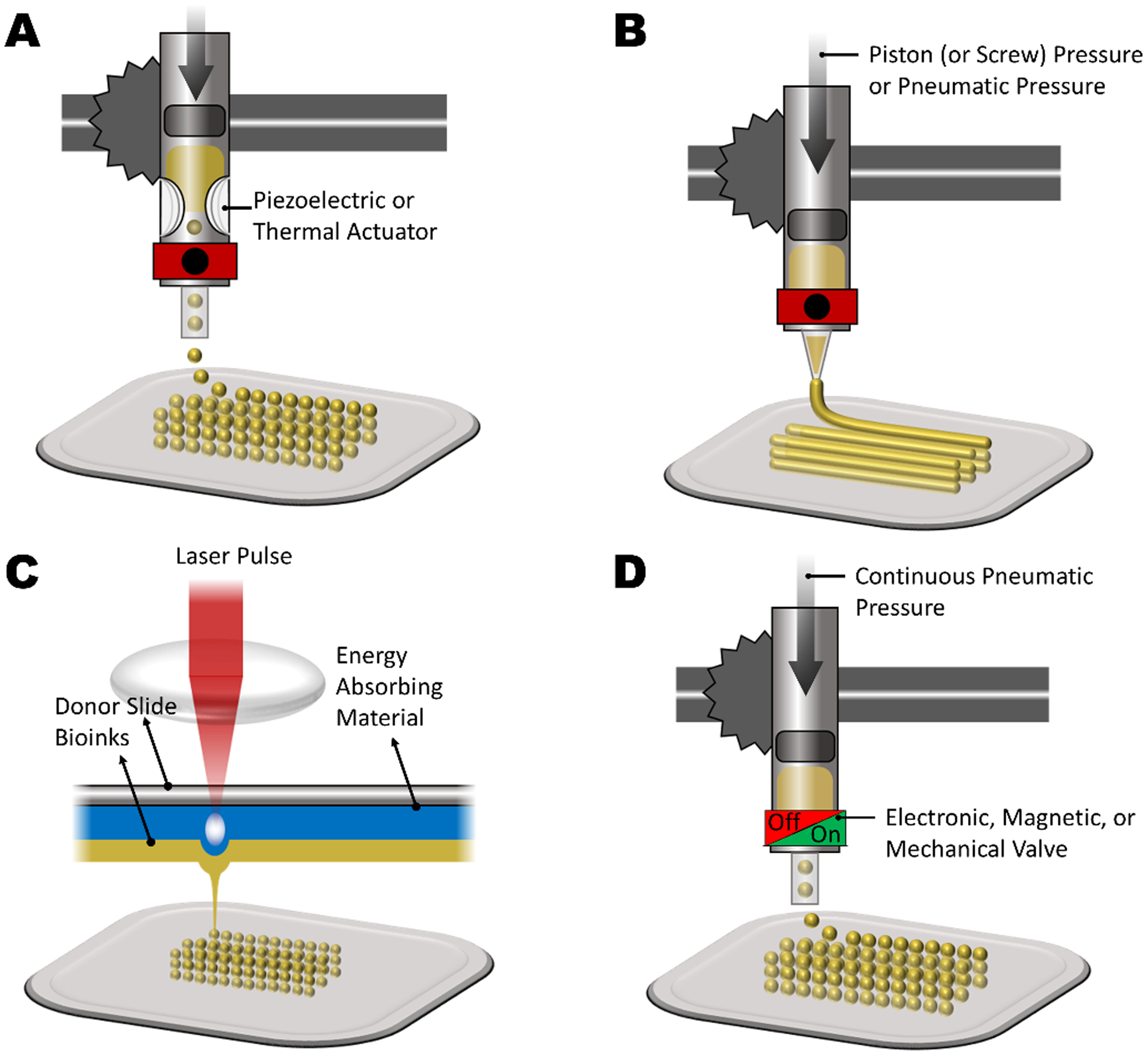
Most common 3D bioprinting techniques. (A) Inkjet bioprinting. (B) Micro-extrusion bioprinting. (C) Laser-assisted bioprinting (LAB). (D) Microvalve bioprinting.
Acknowledgement
The financial support from the National Institutes of Health (R01-AR073822, R01-AR077132) are gratefully acknowledged.
Biographies

Ali Tamayol is an Associate Professor at the Department of Biomedical Engineering at the University of Connecticut Health Center. He received his PhD in engineering science from Simon Fraser University in 2011, followed by Postdoctoral Fellowships in Biomedical Engineering at McGill University and Harvard Medical School. His research involves design, fabrication, and characterization of biomedical systems and biomaterials for solving unmet medical needs. He has been the recipient of several awards including the NSERC Postdoctoral Fellowship, the BCIC Scholar Award, and the Alinasab Prize of ISME.

Mehdi Kazemzadeh-Narbat is a former FDA medical device lead reviewer and acting team lead who provides guidance on regulatory strategies and submissions development across various therapies including orthopedic, dental, general hospital, wound dressings, cardiovascular, neurologic, antimicrobial devices, drugs, and combination products. He is also an expert in the field of Biocompatibility and Orthopedic animal study design. He was a research engineer supervisor at Cook Biotech Inc. and a postdoctoral fellow at Harvard-MIT Division of Health Sciences and Technology. Dr. Kazemzadeh-Narbat received his Ph.D. in biomedical engineering from the University of British Columbia in 2012. He has published over 30 peer-reviewed journal articles, with about 2100 citations and h-index 18.

Pejman Ghelich is a Biomedical Engineering PhD candidate at the University of Connecticut. He completed his Chemical Engineering B.Sc. at Iran University of Science and Technology followed by a M.Sc. in Biotechnology from University of Tehran. Previously he was working on design and fabrication of neural interfaces using the Center for Nanoscale Systems’ (CNS) facilities at Harvard University. Having an extended background in microfabrication, microfluidics, electrochemistry, and biotechnology, his research is focused on engineering the next class of porous biomaterials for 3D bioprinting and minimally invasive wound dressings.
Contributor Information
Pejman Ghelich, Department of Biomedical Engineering, University of Connecticut, Farmington, Connecticut, 06030, USA.
Mehdi Kazemzadeh-Narbat, Musculoskeletal Clinical Regulatory Advisers (MCRA), Washington DC, US.
Alireza Hassani Najafabadi, Department of Biomedical Engineering, University of Connecticut, Farmington, Connecticut, 06030, USA.
Mohamadmahdi Samandari, Department of Biomedical Engineering, University of Connecticut, Farmington, Connecticut, 06030, USA.
Adnan Memic, Center of Nanotechnology, King Abdulaziz University, Jeddah, 21589 Saudi Arabia.
Ali Tamayol, Department of Biomedical Engineering, University of Connecticut, Farmington, Connecticut, 06030, USA.
References
- [1].Giannoudis PV, Dinopoulos H, Tsiridis E, Injury 2005, 36 Suppl 3, 20. [DOI] [PubMed] [Google Scholar]
- [2].M. D and Rozalia Dimitriou PVG, Jones Elena, BMC Med. 2011, 9, 1. [DOI] [PMC free article] [PubMed] [Google Scholar]
- [3].Campana V, Milano G, Pagano E, Barba M, Cicione C, Salonna G, Lattanzi W, Logroscino G, J. Mater. Sci. Mater. Med 2014, 25, 2445. [DOI] [PMC free article] [PubMed] [Google Scholar]
- [4].Robbins S, Lauryssen C, Songer MN, Clin. Spine Surg 2017, 30, E192. [DOI] [PMC free article] [PubMed] [Google Scholar]
- [5].Seth Greenwald A, Scott Boden DD, Goldberg VM, Yaszemski M, Heim CS, Jbjs 2001, 83, 98. [Google Scholar]
- [6].Einhorn TA, Gerstenfeld LC, Nat. Rev. Rheumatol 2015, 11, 45. [DOI] [PMC free article] [PubMed] [Google Scholar]
- [7].Wang W, Yeung KWK, Bioact. Mater 2017, 2, 224. [DOI] [PMC free article] [PubMed] [Google Scholar]
- [8].Bilezikian TJ, Raisz JP, & Martin LG, Acad. Press 2008. [Google Scholar]
- [9].Currey JD, J. Biomech 1969, 2, 477. [DOI] [PubMed] [Google Scholar]
- [10].Frost HM, Metab. Bone Dis. Relat. Res 1983, 4, 281. [DOI] [PubMed] [Google Scholar]
- [11].Rahn BA, Otolaryngol. Clin. North Am 1987, 20, 425—440. [PubMed] [Google Scholar]
- [12].DeLacure MD, Otolaryngol. Clin. North Am 1994, 27, 859. [PubMed] [Google Scholar]
- [13].Butler RJ, Marchesi S, Royer T, Davis IS, J. Orthop. Res Sept. 2007, 25, 1121. [DOI] [PubMed] [Google Scholar]
- [14].Khan SN, Cammisa FP, Sandhu HS, Diwan AD, Girardi FP, Lane JM, J. Am. Acad. Orthop. Surg 2005, 13, 77. [PubMed] [Google Scholar]
- [15].Sadat-Shojai M, Khorasani MT, Dinpanah-Khoshdargi E, Jamshidi A, Acta Biomater 2013, 9, 7591. [DOI] [PubMed] [Google Scholar]
- [16].Nichol JW, Koshy ST, Bae H, Hwang CM, Yamanlar S, Khademhosseini A, Biomaterials 2010, 31, 5536. [DOI] [PMC free article] [PubMed] [Google Scholar]
- [17].Gulati K, Aw MS, Findlay D, Losic D, Ther. Deliv 2012, 3, 857. [DOI] [PubMed] [Google Scholar]
- [18].Mohammadi M, Mousavi Shaegh SA, Alibolandi M, Ebrahimzadeh MH, Tamayol A, Jaafari MR, Ramezani M, Control J. Release 2018, 274, 35. [DOI] [PubMed] [Google Scholar]
- [19].Dlaska CE, Andersson G, Brittberg M, Suedkamp NP, Raschke MJ, Schuetz MA, Curr. Mol. Biol. Reports 2015, 1, 61. [Google Scholar]
- [20].Daculsi G, Fellah BH, Miramond T, Durand M, Irbm 2013, 34, 346. [Google Scholar]
- [21].Carson JS, Bostrom MPG, Injury 2007, 38, DOI 10.1016/j.injury.2007.02.008. [DOI] [PubMed] [Google Scholar]
- [22].Roberts TT, Rosenbaum AJ, Organogenesis 2012, 8, 114. [DOI] [PMC free article] [PubMed] [Google Scholar]
- [23].Scheinpflug J, Pfeiffenberger M, Damerau A, Schwarz F, Textor M, Lang A, Schulze F, Genes (Basel). 2018, 9, DOI 10.3390/genes9050247. [DOI] [PMC free article] [PubMed] [Google Scholar]
- [24].Hutmacher DW, Biomater. Silver Jubil. Compend 2000, 21, 175. [Google Scholar]
- [25].XIAOHUA LIU and PETER XMA, Ann. ofBiomedical Eng 2004, 32, 477. [Google Scholar]
- [26].Chou CH, Shrestha S, Yang CD, Chang NW, Lin YL, Liao KW, Huang WC, Sun TH, Tu SJ, Lee WH, et al. , Nucleic Acids Res 2018, 46, D296. [DOI] [PMC free article] [PubMed] [Google Scholar]
- [27].Stevenson Sharon, Orthop. Clin 1999, 30, 543. [DOI] [PubMed] [Google Scholar]
- [28].Griffith CK, Miller C, Sainson RCA, Calvert JW, Jeon NL, Hughes CCW, George SC, Tissue Eng. 2005, 11, 257. [DOI] [PubMed] [Google Scholar]
- [29].Mauffrey Cyril BT, Barlow, Smith W, J. Am. Acad. Orthop. Surg 2015, 23, 143. [DOI] [PubMed] [Google Scholar]
- [30].Bauer TW, Clin. Orthop. Relat. Res 2007, 51, 729. [DOI] [PubMed] [Google Scholar]
- [31].De Long WG, Einhorn TA, Koval K, Mckee M, Smith W, Sanders R, Watson T, J. Bone Jt. Surg 2007, 649. [DOI] [PubMed] [Google Scholar]
- [32].Stevenson S, J. Bone Jt. Surg 1987, American V, 573. [PubMed] [Google Scholar]
- [33].Stevenson S;Li X;Martin B;, J. Bone Jt. Surg 1991, 73, 1143. [PubMed] [Google Scholar]
- [34].Oonishi H, Iwaki Y, Kin N, Kushitani S, Murata N, Wakitani S, Imoto K, J. Bone Jt. Surg. - Ser. B 1997, 79, 87. [DOI] [PubMed] [Google Scholar]
- [35].Schwartz C, Bordei R, Eur. J. Orthop. Surg. Traumatol 2005, 15, 191. [Google Scholar]
- [36].Greenwald AS, Boden SD, Barrack RL, Bostrom MP, Goldberg VM, Yaszemski MJ, Heim CS. The evolving role of bone-graft substitutes, InProc. of the Am. Acad. of Orthop. Surg. 77th Ann. Mtg 2010, 6. [Google Scholar]
- [37].Wu S, Liu X, Yeung KWK, Liu C, Yang X, Mater. Sci. Eng. R Reports 2014, 80, 1. [Google Scholar]
- [38].Zwingenberger S, Nich C, Valladares RD, Yao Z, Stiehler M, Goodman SB, BioDrugs 2012, 26, 245. [DOI] [PMC free article] [PubMed] [Google Scholar]
- [39].H D, DMW-Deutsche Medizinische Wochenschrift 1893, 19, 445. [Google Scholar]
- [40].Eggli PS, Muller W, Schenk RK, Clin. Orthop. Relat. Res 1988, 127. [PubMed] [Google Scholar]
- [41].Mucalo M (Ed.), Hydroxyapatite (HAp) for Biomedical Applications, Elsevier, 2015. [Google Scholar]
- [42].Välimäki VV, Aro HT, Scand. J. Surg 2006, 95, 95. [DOI] [PubMed] [Google Scholar]
- [43].Ramírez Rodríguez GB, Patrício TMF, Delgado López JM, in Bone Repair Biomater. (Second Ed. (Eds: Pawelec KM, Planell JA), Woodhead Publishing, 2019, pp. 199–232. [Google Scholar]
- [44].Poncin-Epaillard F, Shavdina O, Debarnot D, Mater. Sci. Eng. C 2013, 33, 2526. [DOI] [PubMed] [Google Scholar]
- [45].Huang YX, Ren J, Chen C, Ren TB, Zhou XY, J. Biomater. Appl 2008, 22, 409. [DOI] [PubMed] [Google Scholar]
- [46].Grémare A, Guduric V, Bareille R, Heroguez V, Latour S, L’heureux N, Fricain JC, Catros S, Le Nihouannen D, J. Biomed. Mater. Res. - Part A 2018, 106, 887. [DOI] [PubMed] [Google Scholar]
- [47].Zhang J, Zhao S, Zhu M, Zhu Y, Zhang Y, Liu Z, Zhang C, J. Mater. Chem. B 2014, 2, 7583. [DOI] [PubMed] [Google Scholar]
- [48].Oh SH, Park SC, Kim HK, Koh YJ, Lee JH, Lee MC, Lee JH, J. Biomater. Sci. Polym. Ed 2011, 22, 225. [DOI] [PubMed] [Google Scholar]
- [49].Sola A, Bertacchini J, D’Avella D, Anselmi L, Maraldi T, Marmiroli S, Messori M, Mater. Sci. Eng. C 2019, 96, 153. [DOI] [PubMed] [Google Scholar]
- [50].Fujihara K, Huang ZM, Ramakrishna S, Satknanantham K, Hamada H, Biomaterials 2003, 24, 2661. [DOI] [PubMed] [Google Scholar]
- [51].Chua CK, Leong KF, Tan KH, Wiria FE, Cheah CM, J. Mater. Sci. Mater. Med 2004, 15, 1113. [DOI] [PubMed] [Google Scholar]
- [52].Ajiro H, Takahashi Y, Akashi M, Fujiwara T, Macromol. Biosci 2012, 12, 1315. [DOI] [PubMed] [Google Scholar]
- [53].Elkhoury K, Russell CS, Sanchez-Gonzalez L, Mostafavi A, Williams TJ, Kahn C, Peppas NA, Arab-Tehrany E, Tamayol A, Adv. Healthc. Mater 2019, 8, 1. [DOI] [PMC free article] [PubMed] [Google Scholar]
- [54].Gibbs RO, Black DM, Dawson CR, & Oreffo JI, J. Tissue Eng. Regen. Med 2016, 10, 187. [DOI] [PubMed] [Google Scholar]
- [55].Tamayol A, Akbari M, Annabi N, Paul A, Khademhosseini A, Juncker D, Biotechnol. Adv 2013, 31, 669. [DOI] [PMC free article] [PubMed] [Google Scholar]
- [56].Turnbull G, Clarke J, Picard F, Riches P, Jia L, Han F, Li B, Shu W, Bioact. Mater 2018, 3, 278. [DOI] [PMC free article] [PubMed] [Google Scholar]
- [57].Stevens B, Yang Y, Mohandas A, Stucker B, Nguyen KT, J. Biomed. Mater. Res. - Part B Appl. Biomater 2008, 85, 573. [DOI] [PubMed] [Google Scholar]
- [58].Preethi Soundarya S, Haritha Menon A, Viji Chandran S, Selvamurugan N, Int. J. Biol. Macromol 2018, 119, 1228. [DOI] [PubMed] [Google Scholar]
- [59].Siemann U, Prog. Colloid Polym. Sci 2005, 130, 1. [Google Scholar]
- [60].Thadavirul N, Pavasant P, Supaphol P, J. Biomed. Mater. Res. - Part A 2014, 102, 3379. [DOI] [PubMed] [Google Scholar]
- [61].Kim HJ, Kim UJ, Leisk GG, Bayan C, Georgakoudi I, Kaplan DL, Macromol. Biosci 2007, 7, 643. [DOI] [PubMed] [Google Scholar]
- [62].Yang Q, Chen L, Shen X, Tan Z, J. Macromol. Sci. Part B Phys 2006, 45 B, 1171. [Google Scholar]
- [63].Azami M, Moztarzadeh F, Tahriri M, J. Porous Mater 2010, 17, 313. [Google Scholar]
- [64].Mondal S, Pal U, Dey A, Ceram. Int 2016, 42, 18338. [Google Scholar]
- [65].Lu L, Peter SJ, Lyman MD, Lai HL, Leite SM, Tamada JA, Vacanti JP, Langer R, Mikos AG, Biomaterials 2000, 21, 1595. [DOI] [PubMed] [Google Scholar]
- [66].Lu L, Peter SJ, Lyman MD, Lai HL, Leite SM, Tamada JA, Uyama S, Vacanti JP, Langer Robert, Mikos AG, Biomaterials 2000, 21, 1837. [DOI] [PubMed] [Google Scholar]
- [67].Mikos JP, Thorsen AG, Czerwonka AJ, Bao LA, Langer Y, Winslow R, and Vacanti DN, Polymer (Guildf). 1994, 35, 1068. [Google Scholar]
- [68].Taherkhani S, Moztarzadeh F, J. Appl. Polym. Sci 2016, 133, DOI 10.1002/app.43523. [DOI] [Google Scholar]
- [69].Liao CJ, Chen CF, Chen JH, Chiang SF, Lin YJ, Chang KY, J. Biomed. Mater. Res 2002, 59, 676. [DOI] [PubMed] [Google Scholar]
- [70].Ma JW, and Choi PX, Tissue Eng. 2001, 7, pp. 23. [DOI] [PubMed] [Google Scholar]
- [71].Leong KF, Cheah CM, Chua CK, Biomaterials 2003, 24, 2363. [DOI] [PubMed] [Google Scholar]
- [72].Martel-Estrada SA, Martínez-Pérez CA, Chacón-Nava JG, García-Casillas PE, Olivas-Armendariz I, Carbohydr. Polym 2010, 81, 775. [Google Scholar]
- [73].Li D, Krantz WB, Greenberg AR, Sani RL, J. Memb. Sci 2006, 279, 50. [Google Scholar]
- [74].Akbarzadeh R, Yousefi AM, J. Biomed. Mater. Res. - Part B Appl. Biomater 2014, 102, 1304. [DOI] [PubMed] [Google Scholar]
- [75].Shao J, Chen C, Wang Y, Chen X, Du C, Polym. Degrad. Stab 2012, 97, 955. [Google Scholar]
- [76].Liu X, Ma PX, Biomaterials 2009, 30, 4094. [DOI] [PMC free article] [PubMed] [Google Scholar]
- [77].Wang YC, Lin MC, Wang DM, Hsieh HJ, Biomaterials 2003, 24, 1047. [DOI] [PubMed] [Google Scholar]
- [78].Zhang R, Ma PX, 1999.
- [79].Wei G, Ma PX, Biomaterials 2004, 25, 4749. [DOI] [PubMed] [Google Scholar]
- [80].Yen C, He H, Lee LJ, Ho WSW, J. Memb. Sci 2009, 343, 180. [Google Scholar]
- [81].Guan J, Fujimoto KL, Sacks MS, Wagner WR, Biomaterials 2005, 26, 3961. [DOI] [PMC free article] [PubMed] [Google Scholar]
- [82].Yousefi AM, Powers J, Sampson K, Wood K, Gadola C, Zhang J, James PF, J. Biomater. Sci. Polym. Ed 2020, 0, 1. [DOI] [PMC free article] [PubMed] [Google Scholar]
- [83].C. P and Kumar R. S. Amit, Nishtha Yadav, Monica Bhatt, Mishra Neeraj K, Res. J. Chem. Sci 2015, 5, 98. [Google Scholar]
- [84].Hench LL, West JONK, 1990, 33.
- [85].Chen QZ, Thouas GA, Acta Biomater. 2011, 7, 3616. [DOI] [PubMed] [Google Scholar]
- [86].Zhu B, Wei W, Ma G, Zhuang Y, Liu J, Song L, Hu X, Wang H, Li J, Supercrit J. Fluids 2015, 97, 1. [Google Scholar]
- [87].Chen QZ, Li Y, Jin LY, Quinn JMW, Komesaroff PA, Acta Biomater. 2010, 6, 4143. [DOI] [PubMed] [Google Scholar]
- [88].Pereira MM, Jones JR, Hench LL, Adv. Appl. Ceram 2005, 104, 35. [Google Scholar]
- [89].Mohammad NF, Ahmad RN, Mohd Rosli NL, Abdul Manan MS, Marzuki M, Wahi A, Mater. Today Proc 2021, DOI 10.1016/j.matpr.2020.11.1023. [DOI]
- [90].Jones JR, Ehrenfried LM, Hench LL, Biomaterials 2006, 27, 964. [DOI] [PubMed] [Google Scholar]
- [91].Paramita P, Ramachandran M, Narashiman S, Nagarajan S, Sukumar DK, Chung TW, Ambigapathi M, J. Mater. Sci. Mater. Med 2021, 32, DOI 10.1007/s10856-020-06478-3. [DOI] [PMC free article] [PubMed] [Google Scholar]
- [92].Manissorn J, Wattanachai P, Tonsomboon K, Bumroongsakulsawat P, Damrongsakkul S, Thongnuek P, Mater. Today Commun 2020, 101730. [Google Scholar]
- [93].Rezwan K, Chen QZ, Blaker JJ, Boccaccini AR, Biomaterials 2006, 27, 3413. [DOI] [PubMed] [Google Scholar]
- [94].Shi X, Su K, Varshney RR, Wang Y, Wang DA, Pharm. Res 2011, 28, 1224. [DOI] [PubMed] [Google Scholar]
- [95].Jaklenec A, Wan E, Murray ME, Mathiowitz E, Biomaterials 2008, 29, 185. [DOI] [PubMed] [Google Scholar]
- [96].Jaklenec A, Hinckfuss A, Bilgen B, Ciombor DM, Aaron R, Mathiowitz E, Biomaterials 2008, 29, 1518. [DOI] [PubMed] [Google Scholar]
- [97].Jiang T, Abdel-Fattah WI, Laurencin CT, Biomaterials 2006, 27, 4894. [DOI] [PubMed] [Google Scholar]
- [98].Jiang T, Khan Y, Nair LS, Abdel-Fattah WI, Laurencin CT, J. Biomed. Mater. Res. - Part A 2010, 93, 1193. [DOI] [PubMed] [Google Scholar]
- [99].Jeon JH, Bhamidipati M, Sridharan BP, Scurto AM, Berkland CJ, Detamore MS, J. Biomed. Mater. Res. - Part B Appl. Biomater 2013, 101 B, 330. [DOI] [PMC free article] [PubMed] [Google Scholar]
- [100].Sill TJ, von Recum HA, Biomaterials 2008, 29, 1989. [DOI] [PubMed] [Google Scholar]
- [101].Huang ZM, Zhang YZ, Kotaki M, Ramakrishna S, Compos. Sci. Technol 2003, 63, 2223. [Google Scholar]
- [102].Hasan A, Memic A, Annabi N, Hossain M, Paul A, Dokmeci MR, Dehghani F, Khademhosseini A, Acta Biomater 2014, 10, 11. [DOI] [PMC free article] [PubMed] [Google Scholar]
- [103].Memic A, Abudula T, Mohammed HS, Joshi Navare K, Colombani T, Bencherif SA, ACS Appl. Bio Mater 2019, 2, 952. [DOI] [PubMed] [Google Scholar]
- [104].Abudula T, Saeed U, Memic A, Gauthaman K, Hussain MA, Al-Turaif H, J. Polym. Res 2019, 26, DOI 10.1007/s10965-019-1772-y. [DOI] [Google Scholar]
- [105].Xie J, Li X, Xia Y, Macromol. Rapid Commun 2008, 29, 1775. [DOI] [PMC free article] [PubMed] [Google Scholar]
- [106].Yoshimoto H, Shin YM, Terai H, Vacanti JP, Biomaterials 2003, 24, 2077. [DOI] [PubMed] [Google Scholar]
- [107].Jin HJ, Chen J, Karageorgiou V, Altman GH, Kaplan DL, Biomaterials 2004, 25, 1039. [DOI] [PubMed] [Google Scholar]
- [108].Hae-Won Kim JCK, Hae-Hyoung Lee, Japanese Soc. Biomater. Aust. Soc. Biomater. Korean Soc. Biomater 2006, 79, 643. [Google Scholar]
- [109].Shin SH, Purevdorj O, Castano O, Planell JA, Kim HW, J. Tissue Eng 2012, 3, 1. [DOI] [PMC free article] [PubMed] [Google Scholar]
- [110].Wang Y, Cui W, Zhao X, Wen S, Sun Y, Han J, Zhang H, Nanoscale 2019, 11, 60. [DOI] [PubMed] [Google Scholar]
- [111].Li H, Zhao C, Wang Z, Zhang H, Yuan X, Kong D, J. Biomater. Sci. Polym. Ed 2010, 21, 803. [DOI] [PubMed] [Google Scholar]
- [112].Yu HS, Jang JH, Il Kim T, Lee HH, Kim HW, J. Biomed. Mater. Res. - Part A 2009, 88, 747. [DOI] [PubMed] [Google Scholar]
- [113].Dhand C, Ong ST, Dwivedi N, Diaz SM, Venugopal JR, Navaneethan B, Fazil MHUT, Liu S, Seitz V, Wintermantel E, et al. , Biomaterials 2016, 104, 323. [DOI] [PubMed] [Google Scholar]
- [114].Abbasizadeh N, Rezayan AH, Nourmohammadi J, Kazemzadeh-Narbat M, Int. J. Polym. Mater. Polym. Biomater 2020, 69, 629. [Google Scholar]
- [115].Eichhorn SJ, Sampson WW, Soc JR. Interface 2005, 2, 309. [DOI] [PMC free article] [PubMed] [Google Scholar]
- [116].Kang MS, Kim JH, Singh RK, Jang JH, Kim HW, Acta Biomater. 2015, 16, 103. [DOI] [PubMed] [Google Scholar]
- [117].Zhang X, Wang C, Liao M, Dai L, Tang Y, Zhang H, Coates P, Sefat F, Zheng L, Song J, et al. , Carbohydr. Polym 2019, 213, 27. [DOI] [PubMed] [Google Scholar]
- [118].Teo WE, Ramakrishna S, Nanotechnology 2006, 17, DOI 10.1088/0957-4484/17/14/R01. [DOI] [PubMed] [Google Scholar]
- [119].Sun J, Vijayavenkataraman S, Liu H, Materials (Basel). 2017, 10, 1. [DOI] [PMC free article] [PubMed] [Google Scholar]
- [120].Vijayavenkataraman S, Zhang S, Lu WF, Fuh JYH, J. Mater. Res 2018, 33, 1999. [Google Scholar]
- [121].Hashimdeen SH, Miodownik M, Edirisinghe MJ, PLoS One 2014, 9, 1. [DOI] [PMC free article] [PubMed] [Google Scholar]
- [122].Wutticharoenmongkol P, Sanchavanakit N, Pavasant P, Supaphol P, Macromol. Biosci 2006, 6, 70. [DOI] [PubMed] [Google Scholar]
- [123].Nam J, Huang Y, Agarwal S, Lannutti J, Tissue Eng. 2007, 13, 2249. [DOI] [PMC free article] [PubMed] [Google Scholar]
- [124].Toprak Ö, Topuz B, Monsef YA, Oto Ç, Orhan K, Karakeçili A, Mater. Sci. Eng. C 2021, 120, DOI 10.1016/j.msec.2020.111738. [DOI] [PubMed] [Google Scholar]
- [125].Bhattarai DP, Kim MH, Park H, Park WH, Kim BS, Kim CS, Chem. Eng. J 2020, 389, 123470. [Google Scholar]
- [126].Townsend-Nicholson A, Jayasinghe SN, Biomacromolecules 2006, 7, 3364. [DOI] [PubMed] [Google Scholar]
- [127].Yeo M, Kim GH, Acta Biomater. 2020, 107, 102. [DOI] [PubMed] [Google Scholar]
- [128].Mooney DJ, Baldwin DF, Suh NP, Vacanti JP, Langer R, Biomaterials 1996, 17, 1417. [DOI] [PubMed] [Google Scholar]
- [129].Dehghani F, Annabi N, Curr. Opin. Biotechnol 2011, 22, 661. [DOI] [PubMed] [Google Scholar]
- [130].Ji C, Annabi N, Khademhosseini A, Dehghani F, Acta Biomater. 2011, 7, 1653. [DOI] [PubMed] [Google Scholar]
- [131].Suh SW, Shin JY, Kim J, Kim J, Beak CH, Kim DI, Kim H, Jeon SS, Choo IW, ASAIO J 2002, 48, 460. [DOI] [PubMed] [Google Scholar]
- [132].Rakovsky A, Gotman I, Rabkin E, Gutmanas EY, J. Mech. Behav. Biomed. Mater 2014, 32, 89. [DOI] [PubMed] [Google Scholar]
- [133].Whang K, Thomas CH, Healy KE, Nuber G, Polymer (Guildf). 1995, 36, 837. [Google Scholar]
- [134].Whang K, Tsai DC, Nam EK, Aitken M, Sprague SM, Patel PK, Healy KE, J. Biomed. Mater. Res 1998, 42, 491. [DOI] [PubMed] [Google Scholar]
- [135].Flauder S, Gbureck U, Müller FA, Acta Biomater. 2014, 10, 5148. [DOI] [PubMed] [Google Scholar]
- [136].Qin K, Parisi C, Fernandes FM, J. Mater. Chem. B 2021, 9, 889. [DOI] [PubMed] [Google Scholar]
- [137].Bicho D, Canadas RF, Gonçalves C, Pina S, Reis RL, Oliveira JM, J. Biomater. Sci. Polym. Ed 2021, 0, 1. [DOI] [PubMed] [Google Scholar]
- [138].Rezaei H, Shahrezaee M, Jalali Monfared M, Ghorbani F, Zamanian A, Sahebalzamani M, Biotechnol. Appl. Biochem 2021, 68, 185. [DOI] [PubMed] [Google Scholar]
- [139].Tamayol A, Akbari M, Annabi N, Paul A, Khademhosseini A, Juncker D, Biotechnol. Adv 2013, 31, 669. [DOI] [PMC free article] [PubMed] [Google Scholar]
- [140].Whitesides GM, Nature 2006, 442, 368. [DOI] [PubMed] [Google Scholar]
- [141].Jun Y, Kang E, Chae S, Lee SH, Lab Chip 2014, 14, 2145. [DOI] [PubMed] [Google Scholar]
- [142].Cheng J, Jun Y, Qin J, Lee SH, Biomaterials 2017, 114, 121. [DOI] [PubMed] [Google Scholar]
- [143].Choi CH, Yi H, Hwang S, Weitz DA, Lee CS, Lab Chip 2011, 11, 1477. [DOI] [PubMed] [Google Scholar]
- [144].Nunes JK, Sadlej K, Tam JI, Stone HA, Lab Chip 2012, 12, 2301. [DOI] [PubMed] [Google Scholar]
- [145].Cho S, Shim TS, Yang SM, Lab Chip 2012, 12, 3676. [DOI] [PubMed] [Google Scholar]
- [146].Jeong W, Kim J, Kim S, Lee S, Mensing G, Beebe DJ, Lab Chip 2004, 4, 576. [DOI] [PubMed] [Google Scholar]
- [147].Thangawng AL, Howell PB, Spillmann CM, Naciri J, Ligler FS, Lab Chip 2011, 11, 1157. [DOI] [PubMed] [Google Scholar]
- [148].Il Ju J, Oh HJ, Kim SR, Lee SH, J. Micromechanics Microengineering 2005, 15, 601. [Google Scholar]
- [149].Hwang CM, Khademhosseini A, Park Y, Sun K, Lee SH, Langmuir 2008, 24, 6845. [DOI] [PubMed] [Google Scholar]
- [150].Hwang CM, Park Y, Park JY, Lee K, Sun K, Khademhosseini A, Lee SH, Biomed. Microdevices 2009, 11, 739. [DOI] [PubMed] [Google Scholar]
- [151].Wen X, Tresco PA, Biomaterials 2006, 27, 3800. [DOI] [PubMed] [Google Scholar]
- [152].Jun Y, Kim MJ, Hwang YH, Jeon EA, Kang AR, Lee SH, Lee DY, Biomaterials 2013, 34, 8122. [DOI] [PubMed] [Google Scholar]
- [153].Jun Y, Kang AR, Lee JS, Jeong GS, Ju J, Lee DY, Lee SH, Biomaterials 2013, 34, 3784. [DOI] [PubMed] [Google Scholar]
- [154].Raof NA, Padgen MR, Gracias AR, Bergkvist M, Xie Y, Biomaterials 2011, 32, 4498. [DOI] [PMC free article] [PubMed] [Google Scholar]
- [155].Ghelich P, Salehi Z, Mohajerzedeh S, Jafarkhani M, Can. J. Chem. Eng 2018, 96, 2342. [Google Scholar]
- [156].Yeh CH, Lin PW, Lin YC, Microfluid. Nanofluidics 2010, 8, 115. [Google Scholar]
- [157].Oh J, Kim K, Won SW, Cha C, Gaharwar AK, Selimović Š, Bae H, Lee KH, Lee DH, Lee SH, et al. , Biomed. Microdevices 2013, 15, 465. [DOI] [PMC free article] [PubMed] [Google Scholar]
- [158].Lan W, Li S, Lu Y, Xu J, Luo G, Lab Chip 2009, 9, 3282. [DOI] [PubMed] [Google Scholar]
- [159].Kinahan ME, Filippidi E, Köster S, Hu X, Evans HM, Pfohl T, Kaplan DL, Wong J, Biomacromolecules 2011, 12, 1504. [DOI] [PMC free article] [PubMed] [Google Scholar]
- [160].Iijima K, Ohyama S, Yuyama K, Shono A, Hashizume M, Polym. J 2018, 50, 1187. [Google Scholar]
- [161].Zhang W, Hou C, Li Y, Zhang Q, Wang H, J. Colloid Interface Sci 2019, 558, 115. [DOI] [PubMed] [Google Scholar]
- [162].Lee BR, Lee KH, Kang E, Kim DS, Lee SH, Biomicrofluidics 2011, 5, DOI 10.1063/1.3576903. [DOI] [PMC free article] [PubMed] [Google Scholar]
- [163].Yamada M, Sugaya S, Naganuma Y, Seki M, Soft Matter 2012, 8, 3122. [Google Scholar]
- [164].Ghorbanian S, Qasaimeh MA, Akbari M, Tamayol A, Juncker D, Biomed. Microdevices 2014, 16, 387. [DOI] [PubMed] [Google Scholar]
- [165].Tamayol A, Najafabadi AH, Aliakbarian B, Arab-Tehrany E, Akbari M, Annabi N, Juncker D, Khademhosseini A, Adv. Healthc. Mater 2015, 4, 2146. [DOI] [PMC free article] [PubMed] [Google Scholar]
- [166].Akbari M, Tamayol A, Laforte V, Annabi N, Najafabadi AH, Khademhosseini A, Juncker D, Adv. Funct. Mater 2014, 24, 4060. [DOI] [PMC free article] [PubMed] [Google Scholar]
- [167].Fallahi A, Yazdi IK, Serex L, Lesha E, Faramarzi N, Tarlan F, Avci H, Costa-Almeida R, Sharifi F, Rinoldi C, et al. , ACS Biomater. Sci. Eng 2020, 6, 1112. [DOI] [PubMed] [Google Scholar]
- [168].Fu Q, Saiz E, Rahaman MN, Tomsia AP, Mater. Sci. Eng. C 2011, 31, 1245. [DOI] [PMC free article] [PubMed] [Google Scholar]
- [169].Gross BC, Erkal JL, Lockwood SY, Chen C, Spence DM, Anal. Chem 2014, 86, 3240. [DOI] [PubMed] [Google Scholar]
- [170].Sears N, Dhavalikar P, Whitely M, Cosgriff-Hernandez E, Biofabrication 2017, 9, DOI 10.1088/1758-5090/aa7077. [DOI] [PubMed] [Google Scholar]
- [171].Lam CXF, Mo XM, Teoh SH, Hutmacher DW, Mater. Sci. Eng. C 2002, 20, 49. [Google Scholar]
- [172].Suwanprateeb J, Kerdsook S, Boonsiri T, Pratumpong P, Polym. Int 2011, 60, 758. [Google Scholar]
- [173].Suwanprateeb J, Sanngam R, Suvannapruk W, Panyathanmaporn T, J. Mater. Sci. Mater. Med 2009, 20, 1281. [DOI] [PubMed] [Google Scholar]
- [174].Becker ST, Bolte H, Schünemann K, Seitz H, Bara JJ, Beck-Broichsitter BE, Russo PAJ, Wiltfang J, Warnke PH, Int. J. Oral Maxillofac. Surg 2012, 41, 1153. [DOI] [PubMed] [Google Scholar]
- [175].Pei X, Zhang B, Fan Y, Zhu X, Sun Y, Wang Q, Zhang X, Zhou C, Mater. Lett 2017, 208, 133. [Google Scholar]
- [176].Zhao L, Pei X, Jiang L, Hu C, Sun J, Xing F, Zhou C, Fan Y, Zhang X, Compos. Part B Eng 2019, 162, 154. [Google Scholar]
- [177].Corcione CE, Gervaso F, Scalera F, Montagna F, Maiullaro T, Sannino A, Maffezzoli A, J. Polym. Eng 2017, 37, 741. [Google Scholar]
- [178].Bose S, Vahabzadeh S, Bandyopadhyay A, Mater. Today 2013, 16, 496. [Google Scholar]
- [179].Hong JM, Kim BJ, Shim JH, Kang KS, Kim KJ, Rhie JW, Cha HJ, Cho DW, Acta Biomater 2012, 8, 2578. [DOI] [PubMed] [Google Scholar]
- [180].Gornet T, 2017, 1.
- [181].Skoog SA, Goering PL, Narayan RJ, J. Mater. Sci. Mater. Med 2014, 25, 845. [DOI] [PubMed] [Google Scholar]
- [182].Melchels FPW, Feijen J, Grijpma DW, Biomaterials 2010, 31, 6121. [DOI] [PubMed] [Google Scholar]
- [183].Kazemzadeh-Narbat M, Rouwkema J, Annabi N, Cheng H, Ghaderi M, Cha BH, Aparnathi M, Khalilpour A, Byambaa B, Jabbari E, et al. , Adv. Healthc. Mater 2017, 6, 1. [DOI] [PubMed] [Google Scholar]
- [184].Kim K, Yeatts A, Dean D, Fisher JP, Tissue Eng. - Part B Rev 2010, 16, 523. [DOI] [PMC free article] [PubMed] [Google Scholar]
- [185].Elomaa L, Teixeira S, Hakala R, Korhonen H, Grijpma DW, Seppälä JV, Acta Biomater. 2011, 7, 3850. [DOI] [PubMed] [Google Scholar]
- [186].Ronca A, Ambrosio L, Grijpma DW, J. Appl. Biomater. Funct. Mater 2012, 10, 249. [DOI] [PubMed] [Google Scholar]
- [187].Ronca A, Ambrosio L, Grijpma DW, Acta Biomater. 2013, 9, 5989. [DOI] [PubMed] [Google Scholar]
- [188].Cooke MN, Fisher JP, Dean D, Rimnac C, Mikos AG, J. Biomed. Mater. Res. - Part B Appl. Biomater 2003, 64, 65. [DOI] [PubMed] [Google Scholar]
- [189].Lan PX, Lee JW, Seol YJ, Cho DW, J. Mater. Sci. Mater. Med 2009, 20, 271. [DOI] [PubMed] [Google Scholar]
- [190].Lee JW, Kang KS, Lee SH, Kim JY, Lee BK, Cho DW, Biomaterials 2011, 32, 744. [DOI] [PubMed] [Google Scholar]
- [191].Gittard SD, Koroleva A, Nguyen A, Fadeeva E, Gaidukeviciute A, Schlie S, Narayan RJ, Chichkov B, 2013, 602. [DOI] [PubMed]
- [192].Dean D, Mott E, Luo X, Busso M, Wang MO, Vorwald C, Siblani A, Fisher JP, Virtual Phys. Prototyp 2014, 9, 3. [Google Scholar]
- [193].Schmidleithner C, Malferrari S, Palgrave R, Bomze D, Schwentenwein M, Kalaskar DM, Biomed. Mater 2019, 14, DOI 10.1088/1748-605X/ab279d. [DOI] [PubMed] [Google Scholar]
- [194].Kadry H, Wadnap S, Xu C, Ahsan F, Eur. J. Pharm. Sci 2019, 135, 60. [DOI] [PubMed] [Google Scholar]
- [195].Gardan J, Int. J. Prod. Res 2016, 54, 3118. [Google Scholar]
- [196].Zein I, Hutmacher DW, Tan KC, Teoh SH, Biomaterials 2002, 23, 1169. [DOI] [PubMed] [Google Scholar]
- [197].Do AV, Khorsand B, Geary SM, Salem AK, Adv. Healthc. Mater 2015, 4, 1742. [DOI] [PMC free article] [PubMed] [Google Scholar]
- [198].Hutmacher DW, Schantz T, Zein I, Ng KW, Teoh SH, Tan KC, J. Biomed. Mater. Res 2001, 55, 203. [DOI] [PubMed] [Google Scholar]
- [199].Park SH, Park DS, Shin JW, Kang YG, Kim HK, Yoon TR, Shin JW, J. Mater. Sci. Mater. Med 2012, 23, 2671. [DOI] [PubMed] [Google Scholar]
- [200].Kim J, McBride S, Tellis B, Alvarez-Urena P, Song YH, Dean DD, Sylvia VL, Elgendy H, Ong J, Hollinger JO, Biofabrication 2012, 4, DOI 10.1088/1758-5082/4/2/025003. [DOI] [PubMed] [Google Scholar]
- [201].Jiao Z, Luo B, Xiang S, Ma H, Yu Y, Yang W, Adv. Ind. Eng. Polym. Res 2019, 2, 196. [Google Scholar]
- [202].Mazzoli A, Med. Biol. Eng. Comput 2013, 51, 245. [DOI] [PubMed] [Google Scholar]
- [203].Tan CM, Chua KH, Leong CK, Naing KF, and Cheah MW, Proc. Inst. Mech. Eng. Part H J. Eng. Med 2005, 219, 183. [DOI] [PubMed] [Google Scholar]
- [204].Williams JM, Adewunmi A, Schek RM, Flanagan CL, Krebsbach PH, Feinberg SE, Hollister SJ, Das S, Biomaterials 2005, 26, 4817. [DOI] [PubMed] [Google Scholar]
- [205].Dyson JA, Genever PG, Dalgarno KW, Wood DJ, Tissue Eng. 2007, 13, 2891. [DOI] [PubMed] [Google Scholar]
- [206].Hayashi T, Maekawa K, Tamura M, Hanyu K, JSME Int. Journal, Ser. A Solid Mech. Mater. Eng 2006, 48, 369. [Google Scholar]
- [207].Hunt JA, Callaghan JT, Sutcliffe CJ, Morgan RH, Halford B, Black RA, Biomaterials 2005, 26, 5890. [DOI] [PubMed] [Google Scholar]
- [208].Simpson RL, Wiria FE, Amis AA, Chua CK, Leong KF, Hansen UN, Chandrasekaran M, Lee MW, J. Biomed. Mater. Res. - Part B Appl. Biomater 2008, 84, 17. [DOI] [PubMed] [Google Scholar]
- [209].Doyle H, Lohfeld S, McHugh P, Med. Eng. Phys 2015, 37, 767. [DOI] [PubMed] [Google Scholar]
- [210].Kang HW, Lee SJ, Ko IK, Kengla C, Yoo JJ, Atala A, Nat. Biotechnol 2016, 34, 312. [DOI] [PubMed] [Google Scholar]
- [211].Memic A, Navaei A, Mirani B, Cordova JAV, Aldhahri M, Dolatshahi-Pirouz A, Akbari M, Nikkhah M, Biotechnol. Lett 2017, 39, 1279. [DOI] [PubMed] [Google Scholar]
- [212].Xing F, Xiang Z, Rommens PM, Ritz U, Materials (Basel). 2020, 13, 1. [DOI] [PMC free article] [PubMed] [Google Scholar]
- [213].Mao JJ, Stosich MS, Moioli EK, Lee CH, Fu SY, Bastian B, Eisig SB, Zemnick C, Ascherman J, Wu J, et al. , Tissue Eng. 2010, 16. [DOI] [PMC free article] [PubMed] [Google Scholar]
- [214].Daly AC, Cunniffe GM, Sathy BN, Jeon O, Alsberg E, Kelly DJ, Adv. Healthc. Mater 2016, 5, 2353. [DOI] [PubMed] [Google Scholar]
- [215].Chimene D, Miller L, Cross LM, Jaiswal MK, Singh I, Gaharwar AK, ACS Appl. Mater. Interfaces 2020, 12, 15976. [DOI] [PubMed] [Google Scholar]
- [216].Compaan AM, Christensen K, Huang Y, ACS Biomater. Sci. Eng 2017, 3, 1519. [DOI] [PubMed] [Google Scholar]
- [217].Byambaa B, Annabi N, Yue K, Trujillo-de Santiago G, Alvarez MM, Jia W, Kazemzadeh-Narbat M, Shin SR, Tamayol A, Khademhosseini A, Adv. Healthc. Mater 2017, 6, 1. [DOI] [PMC free article] [PubMed] [Google Scholar]
- [218].Chocholata P, Kulda V, Babuska V, Materials (Basel). 2019, 12, DOI 10.3390/ma12040568. [DOI] [PMC free article] [PubMed] [Google Scholar]
- [219].Wilson WC, Boland T, Anat. Rec. - Part A Discov. Mol. Cell. Evol. Biol 2003, 272, 491. [DOI] [PubMed] [Google Scholar]
- [220].Cui X, Breitenkamp K, Finn MG, Lotz M, D’Lima DD, Tissue Eng. - Part A 2012, 18, 1304. [DOI] [PMC free article] [PubMed] [Google Scholar]
- [221].Cui X, Gao G, Qiu Y, Biotechnol. Lett 2013, 35, 315. [DOI] [PubMed] [Google Scholar]
- [222].Takagi D, Lin W, Matsumoto T, Yaginuma H, Hemmi N, Hatada S, Seo M, Int. J. Bioprinting 2019, 5, 27. [DOI] [PMC free article] [PubMed] [Google Scholar]
- [223].Xu T, Jin J, Gregory C, Hickman JJ, Boland T, Biomaterials 2005, 26, 93. [DOI] [PubMed] [Google Scholar]
- [224].Pepper ME, Seshadri V, Burg TC, Burg KJL, Groff RE, Biofabrication 2012, 4, DOI 10.1088/1758-5082/4/1/011001. [DOI] [PubMed] [Google Scholar]
- [225].Wang X, Ao Q, Tian X, Fan J, Wei Y, Hou W, Tong H, Bai S, Materials (Basel). 2016, 9, 1. [DOI] [PMC free article] [PubMed] [Google Scholar]
- [226].Panwar A, Tan LP, Molecules 2016, 21, DOI 10.3390/molecules21060685. [DOI] [Google Scholar]
- [227].Cui X, Boland T, Biomaterials 2009, 30, 6221. [DOI] [PubMed] [Google Scholar]
- [228].Zhang X, Zhang Y, Cell Biochem. Biophys 2015, 72, 777. [DOI] [PubMed] [Google Scholar]
- [229].Nair K, Gandhi M, Khalil S, Yan KC, Marcolongo M, Barbee K, Sun W, Biotechnol. J 2009, 4, 1168. [DOI] [PubMed] [Google Scholar]
- [230].Ozbolat IT, Hospodiuk M, Biomaterials 2016, 76, 321. [DOI] [PubMed] [Google Scholar]
- [231].Gao Q, He Y, zhong Fu J, Liu A, Ma L, Biomaterials 2015, 61, 203. [DOI] [PubMed] [Google Scholar]
- [232].Guillotin B, Souquet A, Catros S, Duocastella M, Pippenger B, Bellance S, Bareille R, Rémy M, Bordenave L, Amédée j J, et al. , Biomaterials 2010, 31, 7250. [DOI] [PubMed] [Google Scholar]
- [233].Zhang Z, Jin Y, Yin J, Xu C, Xiong R, Christensen K, Ringeisen BR, Chrisey DB, Huang Y, Appl. Phys. Rev 2018, 5, DOI 10.1063/1.5053979. [DOI] [Google Scholar]
- [234].Dinca V, Kasotakis E, Catherine J, Mourka A, Ranella A, Ovsianikov A, Chichkov BN, Farsari M, Mitraki A, Fotakis C, Nano Lett 2008, 8, 538. [DOI] [PubMed] [Google Scholar]
- [235].Colina M, Serra P, Fernández-Pradas JM, Sevilla L, Morenza JL, Biosens. Bioelectron 2005, 20, 1638. [DOI] [PubMed] [Google Scholar]
- [236].Schiele NR, Chrisey DB, Corr DT, Tissue Eng. - Part C Methods 2011, 17, 289. [DOI] [PMC free article] [PubMed] [Google Scholar]
- [237].Shanjani Y, Pan CC, Elomaa L, Yang Y, Biofabrication 2015, 7, DOI 10.1088/1758-5090/7/4/045008. [DOI] [PubMed] [Google Scholar]
- [238].Narazaki A, Oyane A, Miyaji H, Appl. Sci 2020, 10, 1. [Google Scholar]
- [239].Xu F, Emre AE, Turali ES, Hasan SK, Moon S, Nagatomi J, Khademhosseini A, Demirci U, Bioeng. Proc. Northeast Conf 2009, 0. [Google Scholar]
- [240].Demirci U, Montesano G, Lab Chip 2007, 7, 1428. [DOI] [PubMed] [Google Scholar]
- [241].Ng WL, Lee JM, Yeong WY, Win Naing M, Biomater. Sci 2017, 5, 632. [DOI] [PubMed] [Google Scholar]
- [242].Faulkner-Jones A, Greenhough S, A King J, Gardner J, Courtney A, Shu W, Biofabrication 2013, 5, DOI 10.1088/1758-5082/5/1/015013. [DOI] [PubMed] [Google Scholar]
- [243].Markstedt K, Mantas A, Tournier I, Martínez Ávila H, Hägg D, Gatenholm P, Biomacromolecules 2015, 16, 1489. [DOI] [PubMed] [Google Scholar]
- [244].Kazimierczak P, Palka K, Przekora A, Biomolecules 2019, 9, 1. [DOI] [PMC free article] [PubMed] [Google Scholar]
- [245].Singh M, Sandhu B, Scurto A, Berkland C, Detamore MS, Acta Biomater. 2010, 6, 137. [DOI] [PMC free article] [PubMed] [Google Scholar]
- [246].Sánchez-Salcedo S, Nieto A, Vallet-Regí M, Chem. Eng. J 2008, 137, 62. [Google Scholar]
- [247].Colosi C, Costantini M, Barbetta A, Pecci R, Bedini R, Dentini M, Langmuir 2013, 29, 82. [DOI] [PubMed] [Google Scholar]
- [248].Kankala RK, Xu XM, Liu CG, Chen AZ, Bin Wang S, Polymers (Basel). 2018, 10, 1. [DOI] [PMC free article] [PubMed] [Google Scholar]
- [249].Chang H-K, Chen P-Y, J. Mater. Res. Technol 2020, 9, 16167. [Google Scholar]
- [250].Dong Y, Liang J, Cui Y, Xu S, Zhao N, Carbohydr. Polym 2018, 197, 183. [DOI] [PubMed] [Google Scholar]
- [251].Doosti-Telgerd M, Mahdavi FS, Moradikhah F, Porgham Daryasari M, Bayrami R, Atashgah, Dolatyar B, Akbari H, Javar, Seyedjafari E, et al. , Int. J. Nanomedicine 2020, 15, 2633. [DOI] [PMC free article] [PubMed] [Google Scholar]
- [252].Mostafavi A, Abudula T, Russell CS, Mostafavi E, Williams TJ, Salah N, Alshahrie A, Harris S, Masoud S, Basri M, et al. , Acta Biomater 2021, DOI 10.1016/j.actbio.2021.03.009. [DOI] [PubMed] [Google Scholar]
- [253].Keriquel V, Oliveira H, Rémy M, Ziane S, Delmond S, Rousseau B, Rey S, Catros S, Amédée J, Guillemot F, et al. , Sci. Rep 2017, 7, 1. [DOI] [PMC free article] [PubMed] [Google Scholar]
- [254].Singh S, Choudhury D, Yu F, Mironov V, Naing MW, Acta Biomater. 2020, 101, 14. [DOI] [PubMed] [Google Scholar]
- [255].Dhawan A, Kennedy PM, Rizk EB, Ozbolat IT, J. Am. Acad. Orthop. Surg 2019, 27, E215. [DOI] [PubMed] [Google Scholar]
- [256].Ying GL, Jiang N, Maharjan S, Yin YX, Chai RR, Cao X, Yang JZ, Miri AK, Hassan S, Zhang YS, Adv. Mater 2018, 30, 1. [DOI] [PMC free article] [PubMed] [Google Scholar]
- [257].Ying G, Jiang N, Parra-Cantu C, Tang G, Zhang J, Wang H, Chen S, Huang NP, Xie J, Zhang YS, Adv. Funct. Mater 2020, 30, 1. [DOI] [PMC free article] [PubMed] [Google Scholar]
- [258].Bao G, Jiang T, Ravanbakhsh H, Reyes A, Ma Z, Strong M, Wang H, Kinsella JM, Li J, Mongeau L, Mater. Horizons 2020, 7, 2336. [DOI] [PMC free article] [PubMed] [Google Scholar]
- [259].Tan YJ, Tan X, Yeong WY, Tor SB, Sci. Rep 2016, 6, 1. [DOI] [PMC free article] [PubMed] [Google Scholar]
- [260].FDA, Guid. Ind. FDA Staff 2011, can be found under https://www.fda.gov/media/80384/download.
- [261].FDA, “Archive F. Combination Product Definition Combination Product Types,” can be found under https://www.fda.gov/combination-products/about-combination-products/combination-product-definition-combination-product-types, 2018.
- [262].FDA, “Medical Device Exemptions 510(k) and GMP Requirements,” can be found under https://www.accessdata.fda.gov/scripts/cdrh/cfdocs/cfpcd/315.cfm, 2021.
- [263].CDRH, CBER, “The 510(k) Program: Evaluating Substantial Equivalence in Premarket Notifications,” can be found under https://www.fda.gov/regulatory-information/search-fda-guidance-documents/510k-program-evaluating-substantial-equivalence-premarket-notifications-510k, 2014.
- [264].FDA, “FDA 510K content,” can be found under https://www.fda.gov/regulatory-information/search-fda-guidance-documents/format-traditional-and-abbreviated-510ks, 2019.
- [265].FDA, “Product Classification Database,” can be found under https://www.accessdata.fda.gov/scripts/cdrh/cfdocs/cfpcd/classification.cfm, 2021.
- [266].FDA, “Devices Approved in 2021,” can be found under https://www.fda.gov/medical-devices/pma-approvals/devices-approved-2021, 2021.
- [267].El Bialy I, Jiskoot W, Reza Nejadnik M, Pharm. Res 2017, 34, 1152. [DOI] [PMC free article] [PubMed] [Google Scholar]
- [268].Arnold PM, Sasso RC, Janssen ME, Fehlings MG, Smucker JD, Vaccaro AR, Heary RF, Patel AI, Goulet B, Kalfas IH, et al. , Spine (Phila. Pa. 1976). 2016, 41, 1075. [DOI] [PubMed] [Google Scholar]
- [269].Kazemzadeh-Narbat M, Cheng H, Chabok R, Alvarez MM, de la Fuente-Nunez C, Phillips KS, Khademhosseini A, Crit. Rev. Biotechnol 2021, 41, 94. [DOI] [PubMed] [Google Scholar]
- [270].Wang H, Garg A, Kazemzadeh-Narbat M, Urish KL, Urish KL, Urish KL, Phillips KS, in Antimicrob. Comb. Devices (Eds: Urish K, Mihalko W), ASTM International, West Conshohocken, PA, 2020, pp. 17–25. [Google Scholar]
- [271].FDA, “Dental Bone Grafting Material Devices - Class II Special Controls Guidance for Industry and FDA Staff,” can be found under https://www.fda.gov/medical-devices/guidance-documents-medical-devices-and-radiation-emitting-products/dental-bone-grafting-material-devices-class-ii-special-controls-guidance-industry-and-fda-staff, 2005.
- [272].FDA, “Resorbable Calcium Salt Bone Void Filler Device - Class II Special Controls Guidance Document for Industry and FDA Staff,” can be found under https://www.fda.gov/medical-devices/guidance-documents-medical-devices-and-radiation-emitting-products/resorbable-calcium-salt-bone-void-filler-device-class-ii-special-controls-guidance-document-industry, 2003.
- [273].FDA, “Device Classification Panels,” can be found under https://www.fda.gov/medical-devices/classify-your-medical-device/device-classification-panels, 2018.
- [274].ACS, “CAS REGISTRY®,” can be found under https://www.cas.org/cas-data/cas-registry, 2021.
- [275].FDA, “Medical Devices Containing Materials Derived from Animal Sources (Except for In Vitro Diagnostic Devices),” can be found under https://www.fda.gov/regulatory-information/search-fda-guidance-documents/medical-devices-containing-materials-derived-animal-sources-except-vitro-diagnostic-devices, 2019. [PubMed]
- [276].FDA, Center for Biologics Evaluation and Research Center for Drug Evaluation and Research, “Q5A Viral Safety Evaluation of Biotechnology Products Derived From Cell Lines of Human or Animal Origin,” can be found under https://www.fda.gov/regulatory-information/search-fda-guidance-documents/q5a-viral-safety-evaluation-biotechnology-products-derived-cell-lines-human-or-animal-origin, 1998.
- [277].FDA, “Technical Considerations for Additive Manufactured Medical Devices,” can be found under https://www.fda.gov/regulatory-information/search-fda-guidance-documents/technical-considerations-additive-manufactured-medical-devices, 2017.
- [278].FDA, “Recommended Content and Format of Non-Clinical Bench Performance Testing Information in Premarket Submissions,” can be found under https://www.fda.gov/regulatory-information/search-fda-guidance-documents/recommended-content-and-format-non-clinical-bench-performance-testing-information-premarket, 2019.
- [279].FDA, Center for Devices and Radiological Health, “General Considerations for Animal Studies for Cardiovascular Devices - Guidance for Industry and FDA Staff,” can be found under https://www.fda.gov/regulatory-information/search-fda-guidance-documents/general-considerations-animal-studies-cardiovascular-devices-guidance-industry-and-fda-staff, 2010.
- [280].FDA, “Use of International Standard ISO 10993-1, “Biological evaluation of medical devices - Part 1: Evaluation and testing within a risk management process” Guidance for Industry and Food and Drug Administration Staff” can be found under https://www.fda.gov/media/85865/download, 2020, 1.
- [281].FDA, “The Least Burdensome Provisions: Concept and Principles,” can be found under https://www.fda.gov/regulatory-information/search-fda-guidance-documents/least-burdensome-provisions-concept-and-principles, 2019.
- [282].Behzadi S, Serpooshan V, Tao W, Hamaly MA, Alkawareek MY, Dreaden EC, Brown D, Alkilany AM, Farokhzad OC, Mahmoudi M, Chem. Soc. Rev 2017, 46, 4218. [DOI] [PMC free article] [PubMed] [Google Scholar]
- [283].Zhao F, Zhao Y, Liu Y, Chang X, Chen C, Zhao Y, Small 2011, 7, 1322. [DOI] [PubMed] [Google Scholar]
- [284].FDA, “Drug Products, Including Biological Products, that Contain Nanomaterials - Guidance for Industry,” can be found under https://www.fda.gov/regulatory-information/search-fda-guidance-documents/drug-products-including-biological-products-contain-nanomaterials-guidance-industry, 2017. [DOI] [PMC free article] [PubMed]
- [285].FDA, “Considering Whether an FDA-Regulated Product Involves the Application of Nanotechnology,” can be found under https://www.fda.gov/regulatory-information/search-fda-guidance-documents/considering-whether-fda-regulated-product-involves-application-nanotechnology, 2014.
- [286].FDA, “Significant Risk and Nonsignificant Risk Medical Device Studies,” can be found under https://www.fda.gov/regulatory-information/search-fda-guidance-documents/significant-risk-and-nonsignificant-risk-medical-device-studies, 2006.
- [287].FDA, “CFR - Code of Federal Regulations Title 21,” can be found under https://www.accessdata.fda.gov/scripts/cdrh/cfdocs/cfcfr/CFRsearch.cfm?CFRPart=812, 2020.
- [288].FDA, “Classification of Products as Drugs and Devices and Additional Product Classification Issues,” can be found under https://www.fda.gov/regulatory-information/search-fda-guidance-documents/classification-products-drugs-and-devices-and-additional-product-classification-issues, 2017.
- [289].FDA, “FDAAA Certification to Accompany Drug, Biological Product, and Device Applications or Submissions,” can be found under https://www.fda.gov/regulatory-information/food-and-drug-administration-amendments-act-fdaaa-2007/fdaaa-certification-accompany-drug-biological-product-and-device-applications-or-submissions, 2018.