

Abstract
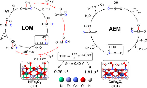
Spinel ferrites, especially Nickel ferrite, NiFe2O4, and Cobalt ferrite, CoFe2O4, are efficient and promising anode catalyst materials in the field of electrochemical water splitting. Using density functional theory, we extensively investigate and quantitatively model the mechanism and energetics of the oxygen evolution reaction (OER) on the (001) facets of their inverse-spinel structure, thought as the most abundant orientations under reaction conditions. We catalogue a wide set of intermediates and mechanistic pathways, including the lattice oxygen mechanism (LOM) and adsorbate evolution mechanism (AEM), along with critical (rate-determining) O–O bond formation barriers and transition-state structures. In the case of NiFe2O4, we predict a Fe-site-assisted LOM pathway as the preferred OER mechanism, with a barrier (ΔG⧧) of 0.84 eV at U = 1.63 V versus SHE and a turnover frequency (TOF) of 0.26 s–1 at 0.40 V overpotential. In the case of CoFe2O4, we find that a Fe-site-assisted LOM pathway (ΔG⧧ = 0.79 eV at U = 1.63 V vs SHE, TOF = 1.81 s–1 at 0.40 V overpotential) and a Co-site-assisted AEM pathway (ΔG⧧ = 0.79 eV at bias > U = 1.34 V vs SHE, TOF = 1.81 s–1 at bias >1.34 V) could both play a role, suggesting a coexistence of active sites, in keeping with experimental observations. The computationally predicted turnover frequencies exhibit a fair agreement with experimentally reported data and suggest CoFe2O4 as a more promising OER catalyst than NiFe2O4 in the pristine case, especially for the Co-site-assisted OER pathway, and may offer a basis for further progress and optimization.
Keywords: oxygen evolution reaction, DFT, reaction mechanism, electrocatalysis, spinel oxides, Ni−Fe oxides, Co−Fe oxides
1. Introduction
Water electrolysis is a well-established method to produce hydrogen from renewable energy sources,1−4 composed of the oxygen evolution reaction (OER) and the hydrogen evolution reaction as the two half reactions involved at the anode and cathode, respectively. The kinetics of the electrochemical water splitting process is greatly hindered by the sluggish anodic OER. The OER is challenging because a difficult oxygen–oxygen bond formation step in addition to four proton-coupled electron transfers under acidic conditions (2H2O → O2 + 4H+ + 4e–) or four hydroxyl-coupled electron transfers under basic conditions (4OH– → O2 + 2H2O + 4e–) are involved. Owing to both difficulties in the oxygen–oxygen bond formation step and because multiple electron transfer is not kinetically favored, the OER is still in need of efficient catalysts to accelerate the reaction and lower the kinetic overpotential. Despite many decades of intensive research, in fact, a sizeable overpotential is observed even on the most active, state-of-the-art precious-metal catalysts, Ru and Ir and their oxides, which otherwise work efficiently under both acidic and alkaline conditions.5−8 Moreover, since the use of precious metals is not sustainable in world-scale applications due to their high cost and scarcity, research is currently focusing on non-noble metals, that is, Fe, Ni, Co, Cu, or other 3d transition metals. Some of these systems are indeed promising and active OER catalysts. For example, Ni-, Fe-, and Co-based oxides are chemically stable in alkaline media, and they show an OER performance not far from that of the oxides of Ru and Ir.9−11 Furthermore, combinations of these metals into bimetallic systems have demonstrated to highly increase the catalytic activity and stability for this electrochemical reaction.12 Especially layered oxyhydroxides13−17 and spinel-type oxides18−21 have attracted significant attention, and many studies have appeared investigating their chemical properties, synthetic methodologies, and catalytic performance.
In particular, spinel-like structures are considered promising OER electrocatalysts due to their high electrical conductivity, structural stability, and catalytic performance, stemming from the multiple valences of the cations and the ability to switch among different oxidation states.22 The general formula of spinel-type oxides is (AB2O4) and consists of a cation A (M+2) that occupy tetrahedral sites and a cation B (M+3) that occupy octahedral sites of the close-packed cubic Fd3̅m[227] structure. Depending on which cations occupy octahedral or tetrahedral sites, the spinel is named as either a normal or inverse spinel structure. If A+2 cations occupy tetrahedral sites and B+3 cations occupy only octahedral sites, the structure is called “normal spinel,” whereas in the inverse spinel structure A+2 cations occupy half of the octahedral sites, while half of the B+3 cations are in tetrahedral sites and the other half occupy octahedral sites (Figure 1).
Figure 1.
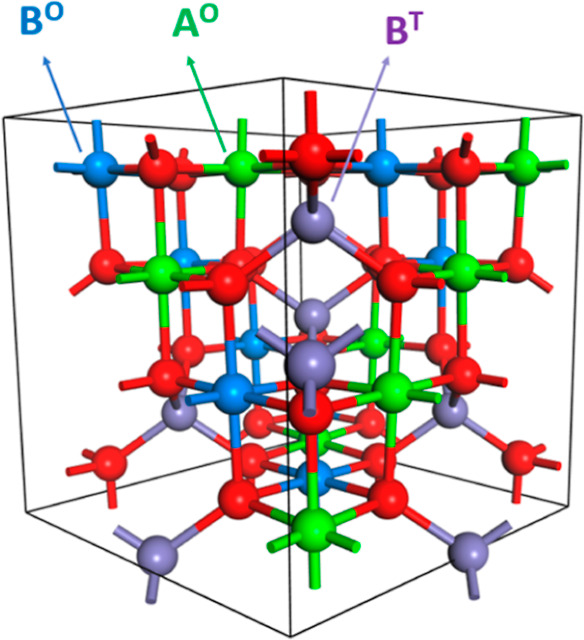
Bulk model (n. AB2O4) for inverse spinel oxide in ball and stick representation. O and T denote octahedral and tetrahedral coordination of A and B metals, respectively.
Among spinel oxide structures, spinel ferrites are of particular interest because of their low cost, high catalytic activity, and durability at high pH.18,22 Fe is considered the active OER catalytic species/site, but synergistic effects are observed when Fe is combined with other metals. In earlier studies, it was reported that addition of iron is beneficial for lowering the overpotential of a nickel oxide electrode,23 therefore, strongly promoting the OER.24,25 Significantly, Singh et al. noted that the NiFe bimetallic compound (spinel NiFe2O4) outperforms pure Fe (spinel Fe3O4) and Ni (cubic NiO) oxides in OER electrocatalytic activity.26 Various successive theoretical studies predicted that controlled Fe doping can reduce the overpotential.27,28 Li and Selloni27 performed a theoretical analysis of key configurations of pure and Fe-doped NiOx systems and suggested that the OER activity can be enhanced when Fe doping is in the range of low to moderate level, and that NiFe2O4 is a promising OER catalyst among the studied Fe-doped NiOx. Xiao et al.(28) emphasized that in addition to high spin Fe stabilizing the O radical in the in (Ni, Fe) OOH systems, closed shell d6 Ni(IV) plays an important role in catalyzing the O–O coupling. At the experimental level, by means of spectroscopic characterization, Landon et al. reported that Fe-doped NiOx contains the spinel NiFe2O4 phase and proposed that this NiFe2O4 phase is responsible for improving the OER activity of the mixed metal oxide systems.29
Among the wide variety of spinel ferrites (MFe2O4, M = Co, Ni, Mn, Cu etc.), several 3d metals have been investigated in addition to Ni. Especially cobalt ferrite (i.e., CoFe2O4) is also in focus as a promising OER catalyst. Si et al. reported that CoFe2O4 and NiFe2O4 exhibited a higher OER activity than MnFe2O4 among prepared mesoporous nanostructured spinel ferrites,30 in good agreement with the trends reported by Li et al.(31) The cobalt/iron synergy in the OER is, therefore, worth investigating, although so far, it has not been explored as much as the synergistic effect of Ni–Fe. In particular, computational modelling could help determining the active sites of Co/Fe oxides, a point which is not fully clear at the experimental level. Indeed, by means of (spectro) electrochemical experiments including EXAFS and XAS Smith et al. reported the coexistence of multiple electrocatalytic sites in a series of iron-cobalt oxides with different compositions and suggested that Fe can act both directly and indirectly as an OER catalyst in this series but were not able to provide a full clarification.32 As we will see below, our calculations indeed suggest that Co and Fe sites could play a synergistic role, and there might be coexistence of active sites in CoFe2O4. In terms of pure Co oxide OER catalysts (e.g., Co3O4, CoOOH), experimental evidence suggests for two site mechanisms containing two Co centers.33,34
At variance with the numerous experimental investigations, theoretical mechanistic studies on OER spinel oxide catalysts are still scarce, despite the fact that an atomistic understanding of the target reaction mechanisms is potentially very useful and possibly decisive to designing electrocatalysts that optimize OER activity and selectivity. Our aim here is to fill this gap by investigating in detail through a DFT approach, the OER reaction mechanisms on inverse-spinel ferrite catalyst NiFe2O4 and CoFe2O4 selected (001) facet. We start with NiFe2O4 (001), on which a previous theoretical study exists,27 and we make progress with respect to existing knowledge by: (i) investigating in detail the mechanisms of the O–O bond formation process via the alternative paths of lattice oxygen mechanism (LOM)35−39 and adsorbate evolution mechanism (AEM),40−42 and (ii) considering a much larger set of reaction intermediates so as to ensure that we explore all possible reaction paths. This allows us to determine a complete reaction free-energy diagram, thus providing the basis for a comparison with experimental kinetics. In addition, we conduct an analogous study by bringing another promising spinel, CoFe2O4, into our focus. We underline that, in the previous theoretical literature on MFe2O4 systems for the OER of NiFe2O4, only a limited number of local minimum intermediates were reported, and the O–O bond formation mechanism was not investigated. The lack of mechanistic research is even more severe for CoFe2O4, for which—to the best of our knowledge—no detailed reaction free-energy profile, and thus, no mechanism has been investigated so far. To the best of our knowledge, the present study is then the first in which the O–O bond formation barrier with transition-state (TS) structures on NiFe2O4 and CoFe2O4 inverse-spinel surfaces for the OER is illustrated and quantitatively modeled. Our calculations show that on NiFe2O4 (001), a Fe-site-assisted mechanism is strongly preferred via a LOM pathway and presents a barrier (ΔG⧧) of the rate-determining-step (rds) occurring for the O–O bond formation of ΔG⧧ = 0.84 eV at U = 1.63 V versus standard hydrogen electrode (SHE), whence a computationally predicted turnover frequency (TOF) of 0.26 s–1 at 400 mV overpotential. As for CoFe2O4 (001), we find that Co and Fe sites could play a synergistic role, and there might be multiple active sites in agreement with experiment. In the Co-site-assisted mechanism, an AEM pathway is favored with the barrier (ΔG⧧ = 0.79 eV at bias > U = 1.34 V vs SHE) corresponding to a TOF of 1.81 s–1 at bias >1.34 V, while in the Fe-site-assisted mechanism, a LOM pathway is favored with the barrier ΔG⧧ = 0.79 eV at U = 1.63 V versus SHE, whence a TOF of 1.81 s–1 at 400 mV overpotential. The computationally predicted turnover frequencies exhibit good agreement with experimentally reported values. Our results also suggest that CoFe2O4 is a more promising OER catalyst than NiFe2O4 in pristine case, especially in the Co-site-assisted OER mechanism.
2. Computational Approach
Spin-polarized density functional theory plus Hubbard correction (DFT + U) calculations were performed in the plane wave and ultrasoft pseudopotential framework,43 as implemented in the Quantum-Espresso suite of codes.44 The PBE45 exchange–correlation functional was used in the DFT part, augmented with Hubbard U parameters chosen as 3.3, 5.5, and 4.5 eV for Fe, Ni, and Co, respectively.27,46 Kinetic energy cutoffs of 40 and 200 Ry were chosen for describing the wave function and the charge density, respectively. Nudged elastic band (NEB) calculations,47 including climbing image (CI),48 were used to find reaction barriers and transition states.
The selected catalysts NiFe2O4 and CoFe2O4 inverse spinel structures are ferrimagnetic,49,50 that is, their ferrimagnetic spin arrangement is ↑↓↑ for M1(Oh)/Fe(Td)/Fe(Oh), (M1 = Ni, Co), respectively, where we use the notation: spin up (↑) and spin down (↓). We indeed found these spin arrangements as a stable state in our calculations. Perron et al. reported computationally that an inverse ferrimagnetic arrangement for NiFe2O4 is the most stable state amongst various calculated spin arrangements.49 Hossain et al.(51) reported that CoFe2O4 is also highly spin-polarized inverse spinel and stated that the exchange interaction between the up and down spin states in the octahedral and tetrahedral regions due to crystal field effects results in a high spin. Caffrey et al.(52) assessed the potential of the ferrimagnetic spinel ferrites NiFe2O4 and CoFe2O4 to act as spin-filtering barriers in magnetic tunnel junctions in agreement with previous calculations. The magnetic moments (μB) of the metal atoms in the bulk were calculated as follows: 1.65, 4.19, −4.11 for Ni, Fe (Oh), Fe(Td), respectively, for NiFe2O4; and 2.67, 4.17, −4.10 for Co, Fe (Oh), Fe(Td), respectively, for CoFe2O4. The magnetization of the octahedral Ni (1.65 μB) can be assigned to the two unpaired electrons of a low-spin t2g6 eg2 configuration, in agreement with its divalent nature (Ni2+, d8). The magnetization of octahedral Co (2.67 μB) can be assigned to the three unpaired electrons of a high-spin t2g5 eg2 configuration, in agreement with its divalent nature (Co2+, d7). The Fe ions in the octahedral and tetrahedral positions have a similar magnetization of about 4.2 μB, which can be assigned to the approximately five unpaired electrons of a high-spin configuration, t2g3 eg2 (Oh site) and e2 t23 (Td site), in agreement with its trivalent nature (Fe3+, d5). Note that since we predict that both spinels are ferrimagnetic in their ground states, the magnetic moments of the Oh and Td regions are opposite in sign. We focus in both cases on the (001) surface, that is, one of the most frequently exposed surface in the spinel structures.27,53−55 Symmetric, nonstoichiometric slabs were utilized, 15 layers thick, corresponding to a total of 55 atoms per unit cell (see the Supporting Information, Figure S1), similarly to previous work.27 To clarify the nomenclature of surface states/configurations employed in the following, we note that our top slab surfaces exposed to adsorbates exhibit 2 metal sites and 4 oxygens, see Figure S1. The 4 oxygens are labeled as O1, O2, O3, and O4 in Figure 2c and also in Figure S1. In addition to the full set of intermediates for LOM and AEM pathways shown in this article, in the Supporting Information Figures S14–S16, we also denote coverage using the following notation: [adsorbate on Fe/adsorbate on O1 and (or) O2\adsorbate on Ni or Co], for example, OH/O1H\H2O indicates that top Fe sites carry OH (*OH), O1 sites are protonated, and the Ni (or Co) sites are covered with water. A 3 × 3 × 1 Monkhorst-Pack k-point mesh was utilized for energy and structural calculations. Slab surface unit cells with dimensions of 5.89 Å × 5.89 Å × 32 Å for NiFe2O4 and 5.93 Å × 5.93 Å × 32 Å for CoFe2O4 were built using experimental bulk-cubic lattice parameters.56
Figure 2.

Coverage patterns on NiFe2O4 (001). (a) Surface covered with adsorbed undissociated water molecules on each metal sites and nonprotonated lattice oxygens. (b) Adsorbed OH (*OH) on the Fe site, while water is still adsorbed (*H2O) on Ni site, and one lattice surface oxygen is protonated. (c) Adsorbed *OH on both Ni and Fe metal sites, while two lattice surface oxygens are protonated. Oxygen, hydrogen, iron, and nickel atoms are colored red, white, violet, and green, respectively.
To model the thermochemistry of the OER, it is convenient to work under acidic conditions because charged intermediates under basic conditions make it difficult to carry out DFT calculations and require tremendous time and effort.57,58 Noting that the OER reaction (2H2O → O2 + 4H+ + 4e–) can be rewritten as (4OH– → 2H2O + O2 + 4e–) under a basic (alkaline) environment, substitution of the water dissociation equilibrium H2O (l) ⇌ H+ (aq) + OH– (aq) into elemental steps naturally allows one to convert the results under acidic into basic conditions.59 Both are equivalent from the thermodynamic perspective. However, the reacting species are different in the two cases, and the kinetic barriers may be affected by the difference. To explore how this may change the mechanism and its energetics, we thus performed charged and implicit solvent calculations for one step (*O + OH– → *OOH + e–) of the OER reaction under alkaline conditions on CoFe2O4 (see the Supporting Information for detail).
In the reactions involving gaseous or liquid molecules such as oxygen, hydrogen, and water, it is essential to include entropy terms when obtaining the system free-energy (G). In our work, we derived the OER free energies using the same scheme as utilized in previous studies.27,60a The total reaction energy (ΔE) of each elementary step was obtained directly via our DFT calculations. The contributions (ΔH, ΔZPE, and TΔS) to the free energies (ΔG) for small molecules (H2O and H2) were added empirically from previous studies27,60a as follows: ΔGi = ΔEi + ΔHi + ΔZPEi – TΔSi (see the Supporting Information, Table S1), which was reported that Li et al.(60a) utilized standard thermodynamic data60b to obtain the T and p contributions to the G values of aqueous H2O and gaseous H2. The free energy of O2 is expressed as G[O2] = 4.92 eV + 2G[H2O] – 2G[H2] according to the OER equilibrium under standard conditions because calculation of the O2 molecule bond energy is difficult to determine accurately using GGA-DFT, as proposed in previous work.58
We considered the SHE as a reference (standard conditions: pH = 0, p = 1 bar, T = 298.15 K), so the proton {G[H+]} and electron {G[e–]} free energies are replaced by 1/2 G[H2] according to the following eq 1
| 1 |
Since the electron–hole pair generation occurs in electrocatalytic processes, it is more convenient to rewrite an elementary step involving protons and holes in eq 2 as eq 3
| 2 |
| 3 |
Then, using the SHE as the reference as implicit in eq 1, we can write the free energy change in elementary steps as eq 4
| 4 |
where G[H2] is the free energy of H2 in the gas phase under standard conditions, and U is the electrode potential versus the SHE, and thus |e|U represents the energy required to generate the electron–hole pair.
3. Results and Discussion
Previous literature modelling OER on the catalytic systems investigated in the present work was limited to few intermediate structures and did not consider associated energy barriers. Disregarding barriers in the OER path is reasonable for the OER steps involving simple deprotonation processes associated with electrochemical oxidation, which can be assumed to be fast, as they typically present barriers of few kcal/mol, as observed in similar Grotthus-like mechanisms of proton transfer in aqueous electrolytes.61,62 This is, however, not justified for the key catalytic step before the final O2 evolution and, in particular, the O–O coupling (oxygen-oxygen bond formation) that is known to exhibit very often a significant barrier.28 Here, in addition to illustrating this key O–O bond formation step, we also explored several coverage patterns in order to determine an overall OER reaction path and to investigate more thoroughly the associated OER catalytic cycle on [Ni, Co]Fe2O4 spinel oxides. We focus in both cases on the (001) surface, that is, the most frequently exposed surface in the spinel structures/nanoparticles,53−55 and has less vacancy in surface metal sites on octahedral positions that are filled with adsorbates (OH, OH2, and OOH). We use the electrochemistry model developed by Nørskov et al.(59) for electrochemical systems to calculate how the relative energies of intermediates depend on the bias U and apply this approximation to the proton electron (H+ + e–) transfers steps (shown in eq 4), considering that the overall charge of the system is constant. For definitiveness, we work at an applied bias of U = 1.48 V versus SHE to deduce the reaction free energies, as this bias is at present the optimal/realistic target of only 0.25 V overpotential and is considered as the one realistically closest to the thermos-neutral voltage for water electrolysis (1.23 V).
3.1. Coverage Patterns
To begin with, undissociated waters were included to cover and fill coordination of each metal site on the (001) surface. Then, coverage by hydroxyls obtained via water dissociation (*OH + *H, and then in a later stage by oxo-groups: *OH → *O + *H) was considered, and the relative affinity of *H2O, *OH, and *O on the metal sites were predicted by calculating the relative energy of the configurations associated with each coverage pattern. The sampling of several coverage patterns on the catalyst surface led us to determine the lowest free-energy OER pathway.
3.1.1. NiFe2O4 and CoFe2O4
In Figure 2, we depict the NiFe2O4 (001) with three different coverage options on the metal sites, together with their relative energetics: (1) adsorbed undissociated waters on each metal sites, (2) adsorbed OH (*OH) on Fe sites, one protonated lattice surface oxygen and adsorbed (*H2O) on Ni sites; (3) adsorbed *OH on both Ni and Fe metal sites and two protonated lattice surface oxygens. Note that the three configurations in Figure 2 have the same overall stoichiometry; thus, the total electronic energies can be directly compared. Note also that, for case (2), the alternative option (*OH on Ni and *H2O on Fe) has been also tried; however, it eventually converged to that illustrated in Figure 2b, which results as the lowest energetically and thus the favored configuration to initiate OER reaction on this catalyst. We can conclude that, while Ni sites mostly prefer *H2O adsorption, Fe sites prefer *OH adsorption as stable resting-state adsorbates. This also suggests that Fe cations are the active sites for the OER reaction to take place, as widely reported in experimental studies.63 Full water dissociation into adsorbed OH on both metal cations with protonated surface oxygen anions (O1 and O2), as shown in Figure 2c, appears to be the least favorable state to initiate the catalytic cycle considering its 0.93 eV higher energy. We note that the neighboring lattice oxygens (O3, O4) are coordinated to the tetrahedral Fe atom in the second layer (see Figure S2 for a side view), and we found that their protonation implies higher energies: it thus seems that coordination of oxygens with tetrahedral metals is not favorable to protonation, possibly because of the coordination angle and its steric reasons or for crystal-field orbital-geometry reasons. We recall, in fact, that crystal field splitting is smaller in the tetrahedral field compared to the octahedral field, and a lesser number of ligands are involved. Moreover, in the tetrahedral crystal field, the d-orbitals (t2, e) do not point directly toward the ligands to reduce electron–electron repulsion, and this can make the tetrahedral field energetically unfavorable to receive electron pairs.
As for CoFe2O4 of (001), we followed a similar protocol with first considering full water coverage (Figure 3a) and then one-by-one dissociated patterns. Similarly to NiFe2O4, dissociated water coverage patterns on the CoFe2O4 surface are the most favorable; however, in this case, both alternatives of one-degree dissociation of water (i.e., *OH on M1, *H2O on M2, and vice versa) resulted as lowest energy states [see Figure 3b1, b2]. Another difference of the CoFe2O4 surface is that the *OH coverage (Figure 3c) is more stable than *H2O coverage (Figure 3a), in stark contrast to NiFe2O4. Considering also that for CoFe2O4, one-degree dissociation states [Figure 3b1,b2] are equally stable on the two metal sites, this might explain why synergistic effects on Co–Fe are stronger than Ni–Fe. Co might be active as much as Fe in this catalyst, suggesting the coexistence of multiple active sites for cobalt-iron oxides, as experimentally reported.32
Figure 3.

Coverage patterns on CoFe2O4 (001). (a) Surface covered with adsorbed undissociated water molecules on each metal sites and nonprotonated lattice oxygens. (b1) Adsorbed OH (*OH) on the Co site, while water is still adsorbed (*H2O) on the Fe site, and one lattice surface oxygen is protonated. (b2) Adsorbed OH (*OH) on the Fe site, while water is still adsorbed (*H2O) on the Co site, and one lattice surface oxygen is protonated. (c) Adsorbed *OH on both Fe and Co metal sites, while two lattice surface oxygens are protonated. Oxygen, hydrogen, iron, and cobalt atoms are colored red, white, violet, and indigo blue, respectively.
We note that, apart from stoichiometric coverage shown in Figures 2 and 3, we also tried off-stoichiometric patterns, with excess H on surface oxygens or excess O bridge atoms for both catalysts (these additional configurations are illustrated in Figures S3 and S4 of the Supporting Information) but observed that off-stoichiometric patterns were not favored under realistic/reaction conditions (U = 1.56–1.63 V), as can be seen in the energetics of Figures S3 and S4 (see the Supporting Information for details).
3.2. OER Mechanisms
3.2.1. NiFe2O4
In the following, we describe the calculated pathways for OER on the NiFe2O4 (001) surface, with the optimized structures illustrated in Figure 4 and the free-energy profile shown in Figure 5. Our description partially overlaps that proposed in ref (27), with the difference that in addition to four intermediate system in previous work, we elucidate an OER with two possible adopted mechanisms (LOM and AEM) and investigate both O–O bond formation and O2 liberation steps. Briefly, in the LOM, O–O formation takes place through direct coupling between an oxygen adsorbed on a metal site and a lattice oxygen, whereas in the AEM, O–O formation takes place on oxygen adsorbed on metal sites only. Illustrated pictorial OER mechanisms for acidic and basic schemes are given in the Supporting Information, Figure S5.
Figure 4.

Optimized structures of the OER intermediates on (001) NiFe2O4. Oxygen, hydrogen, iron, and nickel atoms are colored red, white, violet, and green, respectively. Alternative notations on top/left corner of each states indicating the coverage on Fe, Ni, O1, and O2 sites are given in the Supporting Information, Figure S14.
Figure 5.

(a) Free Energy (G, eV) profiles that represent the LOM catalytic cycle of the OER on (001) NiFe2O4 at U = 0 V (black, red for the oxo path) and U = 1.48 V (green, purple for the oxo path) vs SHE. (b) Overarching mechanistic catalytic cycle labeled with the same notations on the intermediates used in the free energy profile and Figure 4.
We start the OER catalytic cycle from the lowest-energy-dissociated water coverage state (Figure 2b) as the first intermediate, also named state 1 from now on (see Figure 4 for a pictorial illustration). First, a proton is released from the lattice oxygen (O1), ending up in state 2 with a free lattice oxygen that, together with the adsorbed OH (*OH) on Fe, will initiate the HO–O bond formation in the next step. An alternative to the path in which O–O bond formation starts from state 2 is to release the first proton from *OH to form an oxo state (*O) on Fe, named state 2′, and the oxo adsorbate can interact directly with a protonated lattice oxygen O1–H to form an O–OH bond: we call this path “oxo path,” and it turns out that this version of the LOM mechanism represents a less favored pathway (Figure 5). In the lowest-energy LOM path, the adsorbed OH (*OH) on Fe in state 2 approaches the free lattice oxygen (O1) to make an O–OH bond on lattice O1 in state 3. In our estimates, state 3 with its *OOH species on the surface is associated with the rds barrier: we call it the TS-like structure because it corresponds to a local minimum state, not a saddle point, but with a very low intrinsic barrier, as we discuss next. To quantify the barrier to reach this state, we performed NEB calculations, including CI, for estimating saddle points. However, CI NEBs mostly failed on this complex spin system, possibly because of spin transition and/or rotation from (*OH, state 2) to (*OOH, state 3 and 4). Simple NEB schemes (without CI) instead converged and are reported in the Supporting Information, see Figure S6 for state 2 to state 3. In these simulations, the NEB algorithm did not find a sizeable barrier from state 2 to state 3, so that the barrier can be assumed to coincide with the reaction energy, that is, 0.8 eV (see Figure S6). Sampling a direct path from state 2 to state 4, the NEB algorithm found a steep saddle point located at 0.95 eV, which is energetically and geometrically similar to the local minimum state 3 (TS-like structure), see Figure S7. We thus use the TS-like structure, state 3, to estimate the barrier for this OER mechanistic pathway. As for the oxo path, CI-NEB for O–O formation from state 2′ to 3′m converged (Figure S8) and is probably numerically more stable because spin transition is not involved as much as in state 3 (*OOH). CI-NEB predict the TS as 1.05 eV higher than state 2′ (note that this barrier is 0.63 eV in a NEB without CI scheme, Figure S8). After state 3′m, the proton on lattice O1 shifted to lattice O2 in state 3′, and then oxo pathway connects to state 6 after water absorption on the Fe site left vacant.
In the lowest-energy LOM pathway, the reason why state 4 is significantly more stable than state 3 is that the *OO-H tail makes a hydrogen bond with the lattice oxygen (O2) in the neighboring cell along the y direction (see Figure S2 for a side image of 4), and the position of the −OH resembles that of a tetrahedrally coordinated-Fe in the bulk. Continuing the OER reaction path, in state 5 a water molecule comes in to adsorb onto the undercoordinated Fe cation, after which the hydrogen of the (*OO–H) species is shifted to a lattice oxygen of neighboring cell in the y axis to protonate the surface, leaving an (*O–O*) species between surface metals in state 6. Then, after a second deprotonation of the back lattice oxygen in state 6, state 7 is formed, and the adsorbed water molecule on Fe releases the third proton into the solution phase, transforming into an adsorbed OH in state 8. In the alternative route, state 5 is connected directly to state 7′ by losing a proton from the water adsorbed on the Fe site, and H of *OOH shifts to lattice O2 by leaving an uncoordinated *OO on lattice, and then losing the proton on lattice O2 and *O–O* coordination results in state 8. After the release of a fourth proton from *OH on Fe (state 8a), *O bends down to make a second bond with the surface (*O–O*) in state 8a″, then finally, O2 is liberated from the surface, as shown in 8b, followed by dissociative water adsorption to re-form state 1. Note that there is no barrier during the O2 formation steps from 8a to 8b (see the corresponding NEB profile in Figure S9).
For the AEM pathway (last row in Figure 4), continuing with the oxo structure state 2′, explicit water approaches the oxo site on Fe and simultaneously yields a proton on the lattice oxygen O2, forming *OOH on Fe as a new O–O bond in state 3aH. Then, surface deprotonations occur one by one in states 3a and 4a. After a fourth and final deprotonation from *OOH to *OO on Fe in 4a, O2 is released to reach state 8b, where AEM reconnects to the LOM path, then followed by dissociative water adsorption to re-form state 1.
In Figure 5, the so-derived free energy profile for OER on NiFe2O4 is shown. In black in Figure 5, we report the free energy profile under standard conditions (pH = 0, T = 298.15 K, P = 1 bar, 0 V bias); in red the oxo path at 0 V, whereas in green (and purple for the oxo path) the free energy profile at an overpotential of 0.25 V (i.e., U = 1.48 V vs SHE) is shown. In detail, a 1.48 U (i.e., electrode potential) is applied to the elementary steps that involve a proton-electron transfer (i.e., deprotonation steps), occurring in four steps during the OER catalytic cycle, that is, from state 1 to 2, from state 6 to 7 (or from state 5 to 7′), from state 7 to 8 (or state 7′ to 8), and from state 8 to 8a. Here, we focus on the reaction barrier that stems from the state 3, where O–O bond formation occurs (i.e., the TS-like structure). The significant barrier while forming this key bond is 0.80 eV, according to our estimate via the TS-like structure. The barrier for the oxo pathway requires 1.05 eV as from state 2′, this step (2′ to TS) is also bias-independent, and it thus seems unfavorable. To the best of our knowledge, there are no predictions in theoretical studies of the critical barrier steps that determine the OER reaction rate on NiFe2O4 spinel structures, so we do not have data to compare with. As for O2 liberation process, the fourth and final proton release from state 8 to 8a requires a costly step at 0 V bias by 1.93 eV by reaching a terminal oxygen (*O) generation on Fe. However, this deprotonation step is facilitated by a high electrochemical potential, requiring a barrier of 0.45 eV at 1.48 V bias, as shown in the green energy profile in Figure 5. Then, the system is stabilized by 0.55 eV as (*O) connects to surface oxygens in state 8a″ and continues to be further stabilized, leaving the triple-connected structure (by 0.44 eV), then finally closing the cycle.
In Figure 6, free energy profile for the AEM pathway is illustrated. In addition to 0 V (black), the free-energy profile at U = 1.48 V versus SHE is also shown in the figure. A higher barrier of 0.94 eV from 2′w to TS (see TS on Figure S10) as a bias-independent step (with the TS at 1.48 eV at 1.48 V) compared to the LOM mechanism is predicted.
Figure 6.

(a) Free energy (G, eV) profiles that represent the AEM catalytic cycle of the OER on (001) NiFe2O4 at U = 0 V (black) and, U = 1.48 V (green) vs SHE. (b) Overarching mechanistic catalytic cycle labeled with the same notations on the intermediates used in the free energy profile and Figure 4.
Overall, therefore, the LOM pathway results to be a lower-barrier pathway compared to the AEM on this catalyst, in agreement with what was suggested in the previous literature on spinel oxides.64−66
With the reaction barriers so derived as a function of the electrochemical potential, we can obtain reaction rates and currents using the classical transition state theory. To estimate a computationally derived TOF of catalytic cycles, transition state theory (TST) is commonly used
where kB is the Boltzmann constant, h is the Planck constant, R is the universal gas constant, and T is the temperature in K, while —ΔG⧧ is the overall total barrier corresponding to the difference in free energy between the resting state and highest saddle point along the reaction path (i.e., of the rds). In the lowest-barrier LOM pathway in Figure 5, the barrier responsible for O–O bond forming (2 to 3) is 0.80 eV and for the oxo path (2′ to TS) is 1.05 eV, and these steps are bias-independent, while the first (1 to 2, for oxo: 1 to 2′) and last (8 to 8a) electrochemical steps require 1.67, 1.82, and 1.93 eV, respectively, at 0 V (no bias), and these steps are bias-dependent, thus corresponding to a free-energy difference of 0.19, 0.34, and 0.44 eV, respectively, at 1.48.V versus SHE. The lowest-energy path then goes from state 1 to state 4via state 3 (nonoxo path), and the TS-like state corresponds to the rate-determining step, with an overall free-energy reaction barrier of 0.19 + 0.80 = 0.99 eV. The predicted TOF at 298 K for the path going from state 1 (i.e., the resting state) to state 3 (0.99 eV) at η = 0.25 V overpotential (U = 1.48.V vs SHE) is 7.61 × 10⁻⁴ s–1. In contrast, in the energy-demanding AEM pathway in Figure 6, the overall barrier from 1 (resting state) to TS is 1.48 eV at η = 0.25 V overpotential (U = 1.48.V vs SHE), and the calculated TOF at 298 K is 4.08 × 10⁻¹² s–1. The predicted TOF of 7.61 × 10⁻⁴ for the LOM path is rather low. However, an increase of the bias by 0.15 eV (i.e., at U = 1.63 V vs SHE, η = 0.40 V) would decrease the overall barrier down to 0.84 eV from state 1 to state 3, and thus increase the predicted TOF to 0.26 s–1. This prediction is not far from and compare favorably with the experimentally reported TOF’s in the study by Lim et al. on mesoporous NiFe2O4 spinel nanoparticles with abundant oxygen vacancies. They report that, at an overpotential of 0.40 V, the TOF of hydrogen-treated NiFe2O4 is 0.086 s–1, whereas the TOF of pristine NiFe2O4 and air-treated NiFe2O4 spinel nanoparticles are 0.017 and 0.053 s–1, respectively.67 Note that we predict a TOF of 0.081 s–1 at an overpotential of 0.37 V. We remark that experimental studies report a wide variety of overpotentials for the OER depending on the synthesis method, substrates, and catalyst loading.9 For example, in the study by Lim et al.,67 the overpotential at 10 mA/cm2 of hydrogen-treated, air-treated, and pristine NiFe2O4 spinel nanoparticles were reported as 389, 410, and 496 mV, respectively. Overpotentials thus vary, with a minimum value reported by Chen et al. for phosphate-ion-modified (P–NiFe2O4) nanosheets, that is, 231 mV at 10 mA/cm2.68
3.2.2. CoFe2O4
To determine the reaction pathway for the OER on the CoFe2O4 (001) system, we refer to the coverage pattern shown in Figure 3 for this system. According to that, we have potentially two initial states [Figure 3b1,b2] that have similar (lowest) energies. In Figure 3b1, Fe sites exhibit H2O and Co sites exhibit *OH as surface-layer adsorbates, whereas in Figure 3b2, Co sites have *H2O and Fe sites have *OH instead. The first hydrogen release step (i.e., deprotonation) allows us to explore two different reaction pathways for this catalyst, as deprotonated states result in different O–O bond formation energetics. In Figures 7 and 10, we show optimized intermediate structures considering both LOM and AEM pathways on Co and on Fe sites, respectively, while Figures 8 and 11 represent LOM free-energy profiles, and Figures 9 and 12 show AEM free-energy profiles on Co and on Fe sites, respectively, on (001) CoFe2O4.
Figure 7.

Optimized structures of the OER intermediates on (001) CoFe2O4 showing OER assisted by Co sites. Oxygen, hydrogen, iron, and cobalt atoms are colored red, white, violet, and indigo blue, respectively. Alternative notations on the top/left corner of each states indicating the coverage on Fe, Co, O1, and O2 sites are given in the Supporting Information, Figure S15.
Figure 10.

Optimized structures of the OER intermediates on (001) CoFe2O4 showing an Fe-site-assisted OER. Oxygen, hydrogen, iron, and cobalt atoms are colored red, white, violet, and indigo blue, respectively. Alternative notations on top/left corner of each states indicating the coverage on Fe, Co, O1, and O2 sites are given in the Supporting Information, Figure S16.
Figure 8.

(a) Free energy (G, eV) profiles that represent for the LOM assisted by Co sites, OER intermediates (shown in Figure 7) of catalytic cycle on (001) CoFe2O4 at U = 0 V (black, blue for the oxo path) and U = 1.48 V vs SHE (green and purple for the oxo path). (b) Overarching mechanistic catalytic cycle labeled with the same notations on the intermediates used in the free energy profile and Figure 7.
Figure 11.

(a) Free energy (G, eV) profiles that represent for the LOM assisted by Fe sites, OER intermediates (shown in Figure 10) of the catalytic cycle on (001) CoFe2O4 at U = 0 V (black, blue for oxo path) and U = 1.48 V vs SHE (green and purple for the oxo path). (b) Overarching mechanistic catalytic cycle labeled with the same notations on the intermediates used in the free energy profile and Figure 10.
Figure 9.

(a) Free energy (G, eV) profiles that represent AEM assisted by Co sites catalytic cycle of OER on (001) CoFe2O4 at U = 0 V (black) and U = 1.48 V (green). (b) overarching mechanistic catalytic cycle labeled with the same notations on the intermediates used in the free energy profile and Figure 7.
Figure 12.

(a) Free energy (G, eV) profiles that represent the AEM assisted by Fe sites on (001) CoFe2O4 at U = 0 V (black) and U = 1.48 V (green). (b) Overarching mechanistic catalytic cycle labeled with the same notations on the intermediates used in the free energy profile and Figure 10.
To illustrate the OER pathways on the CoFe2O4 surface, we start with one of the lowest energetic dissociated water coverage states (Figure 3b1) as the first intermediate, which will be named as state 9 (See Figure 7) from now on, in which Fe sites are adsorbed with H2O and Co sites adsorbed with *OH. In state 10, a first deprotonation takes place from the O1 lattice oxygen, and, importantly, it ends up with a much more stable deprotonated state compared to NiFe2O4. Alternatively, in the oxo path of the LOM pathway on this catalyst, the first deprotonation occurs on *OH adsorbed on Co and results in an oxo *O on the cobalt site, however, corresponding to a high-energy (2.13 eV) state 10′, making it unfavorable. From state 10, O–O bond formation occur as *OO-H on the surface with participating *OH on Co site to state 11, a local minimum that we interpret again as the TS-like structure, as discussed above for state 3. After the O–O bond is formed, *OO-H reorients itself in state 12 and gets stabilized by making a hydrogen bond with a lattice oxygen in neighboring cell along the y direction as for state 4 above. In state 13, a water molecule comes to adsorb on an octahedrally coordinated surface Fe site and stabilizes the energy by 0.34 eV (Figure 8) in contrast to the NiFe case in which we found a small destabilization from state 4 to state 5 by 0.05 eV. When the hydrogen of *OO-H shifts to the lattice oxygen in the neighboring unit cell, a (*O–O*) species is formed between lattice surface atoms in state 14. Then, consecutive deprotonation steps occur, connecting the states 14 to 15 from the surface and 15 to 16 to make *OH on Co. Finally, to prepare the O2 liberation step, a fourth and last proton is lost from the adsorbed *OH on Co to create a terminal oxygen (*O) in state 16a′, followed by leaning down to connect with surface-bounded oxygens in state 16a″ that leads to O2 liberation from the surface in state 16b by breaking the previous triple coordination with the surface. In order to close the cycle from 16b to 9, this step is followed by dissociative water adsorption on the exposed Co to re-form state 9.
In Figure 8, the energetics of OER intermediates (from state 9 to 16b) are shown in the free energy profile to illustrate this first catalytic cycle on CoFe2O4. Again, the black profile (blue for oxo path) shows the energetics at 0 V under standard conditions, whereas in the green (purple for oxo) profiles, an overpotential of 0.25 V (i.e., U = 1.48 V vs SHE) is applied to predict the reaction free energies.
As the most important observation and comparison with the previous NiFe case, the first deprotonated state (state 10) in this path is much more stable than in the NiFe2O4 pathway shown earlier, and a large barrier of 1.17 eV is required from state 10 to 11 (TS-like structure). Indeed, the significant highest point (TS-like structure, state 11) that stems from (*OOH) formation resulted in an energy of 1.03 eV with respect to state 9, significantly higher than in the corresponding OER path on NiFe2O4. The NEB for 10′ to 11′m for the oxo path did not converge, but it seems unlikely to produce a transition state lower that of state 11, considering that the final state (state 11′m) is already close to the energy of state 11. As we will also show below in Figure 9, the energy of state 10′ is 0.65 eV at U = 1.48 V versus SHE, and it already corresponds to the highest point along the AEM path, whereas the final state of the missing NEB (state 11′m) in the LOM pathway is already 0.92 eV at U = 1.48 V versus SHE (Figure 8). There is also a smaller barrier (0.51 eV) observed from state 13 to 14 in which the hydrogen bond interaction between lattice oxygen (O2) breaks down with (*O–O*) formation on surface in state 14. As for the fourth and final deprotonation step (state 16 to 16a), it requires less energy (1.32 eV at 0 V bias, −0.16 eV at 1.48 V) to obtain terminal *O on the cobalt site (16a″) than in the NiFe2O4 pathway (8 to 8a). As the state 16a is more stabilized, *O bending down to surface oxygens in the state 16″ requires a small barrier as 0.26 eV.
In Figure 9, the free energy profile for the AEM pathway is illustrated at U = 0 V (black) and U = 1.48 V (green). Although state 10′ requires a high energy of 2.13 eV to have oxo on Co sites, an explicit water interaction in 10′w stabilizes the surface by 0.34 eV, and then O–O bond formation is assisted with explicit water leaving its proton to a surface oxygen (O2) to give rise to *OOH on Co sites. According to NEB calculations (not-CI), the barrier required for this O–O formation step was found to be 0.32 eV. This makes the AEM pathway more favorable than the LOM pathway, when OER is assisted by Co. After that point, surface deprotonations occur one by one in state 11a and 12a. After a fourth and final deprotonation from *OOH on Co in 12a, O2 releases in state 16b (AEM connects to LOM here), followed by dissociative water adsorption to re-form state 9.
The AEM pathway gives the lowest-energy intermediates and barrier for CoFe2O4 (001) when the Co site assists the OER. The calculated TOF is based on the barrier (ΔG⧧) of the first electrochemical step: from state 9 to state 10′, which is 0.65 eV at 1.48 V, to which the free-energy difference with respect to the resting state 10 (also illustrated in Figure 9) should be added for a total overall ΔG⧧ of 0.79 eV. Note that the state 10 should be considered as the resting state for all bias >1.34 V. In conclusion, at U = 1.48 V, the barrier from state 10 to 10′ is 0.79 eV, and the corresponding TOF will be 1.81 s–1, to be compared with the one predicted on NiFe2O4 (001) of 0.26 s–1 at 0.40 V overpotential. Here, we recall that Goddard et al. recently reported that the favorable mechanism for the OER on Co single sites is AEM for the Co doping-TiO2 catalyst, unlike the dominant LOM in perovskites and oxides, and at 1.53 and 1.63 V (300 and 400 mV OER overpotential), the computationally predicted TOF with the grand canonical QM (GCQM) method were reported to be 13.7 and 307.4 s–1, respectively, alongside experimentally reported values of 6.6 ± 1.2 and 181.4 ± 28 s–1.69
As for the energy-demanding LOM pathway for the Co-site-assisted OER in Figure 8, the overall barrier, which is bias-independent, from resting state 10 to state 11 is 1.17 eV, and the corresponding TOF is 6.97 × 10⁻⁷ s–1.
In Figure 10, we show alternative optimized structures for CoFe2O4, in which Co sites are exposed to H2O this time (as the Ni sites in the NiFe2O4 scheme), and Fe sites assist OER. In Figure 11, free energy profiles for LOM pathways are shown. As illustrated in Figure 3b2, this pattern of dissociated water coverage also gives the lowest energetic as in Figure 3b1 (aka state 9). From now on, we call this (Figure 3b2) configuration state 17 as a starting intermediate, and again we investigate two routes after state 17, including the oxo pathway of LOM. After a first proton release from lattice oxygen in state 17, state 18 is formed 0.25 eV higher in energy compared to state 10. In state 19 (TS-like structure), O–O bond formation occur (0.83 eV barrier) as *OO-H on the surface formed by *OH adsorbed on the Fe site, and subsequently, the surface is stabilized by 0.64 eV via rearrangement of the *OO-H position in state 20. The TS-like structure (state 19) estimate gives us the barrier at the point where the O–O bond is formed from state 18 to state 20. Alternatively, in the oxo pathway (Figure 11), after state 17, Fe forms the oxo and requires a bit more energy to form the intermediate 18′ (1.92 eV at 0 V, 0.44 eV at 1.48 V) in which *O on the Fe site approaches the protonated lattice oxygen O1. NEB calculations (no CI) found a barrier of 0.68 eV while forming O–OH on the lattice in state 19′m. Note that this barrier is bias-independent. Another slight difference for this path compared to the Co-assisted OER scheme is that when a new water comes to adsorb on the empty metal site (Fe this case) in state 21, the system is destabilized by 0.1 eV (Figure 11) in contrast to state 13 (Figure 8). Note that, in this stage of the reaction and state of the surface, a similar destabilizing trend was observed in the LOM pathway of NiFe2O4, in which the Fe site was similarly undercoordinated and able to accept water during the step from state 4 and 5. In comparison, it seems that Co sites are comparatively more stabilized by completing their 6th coordination valence with water. Then, in state 22, after the hydrogen shifts from (*OO-H) to back lattice oxygen, an (*O–O*) species is formed on the surface with a barrier of only 0.04 eV. After the release of a second proton from the back lattice, oxygen transforms the surface into state 23, a third proton releases from the H2O adsorbed on Fe leads to state 24. As an alternative route, state 21 can connect to state 23′ by shifting the hydrogen of (*OOH) to the lattice oxygen O2 of the neighboring cell in the y direction and losing a third proton from the surface lattice O2 ends up in state 24. The fourth and last proton release from *OH on Fe to get a terminal O (*O) (state 24a) requires a costly step (2.15 eV at 0 V bias, i.e., 0.67 eV at 1.48 V vs SHE), then *O bends down to connect with the surface (*O–O*) in state 24a″ and stabilizes the system by 0.63 eV. Finally, O2 is released from the surface by breaking down its triple coordination from state 24a″ to state 24b, with a stabilization of 0.80 eV. After liberating O2, dissociative water adsorption occurs to close the cycle and to re-form state 17.
In Figure 12, in the case of the AEM pathway (last column in Figure 10 for optimized structures), continuing with oxo structure state 18′ (1.92 eV at 0 V), explicit water approaches the oxo site on Fe in state 18′w and leaves one proton on lattice oxygen O2, forming *OOH on Fe as a new O–O bond with the AEM scheme in state 19aH by stabilizing 0.44 eV. Note that NEB calculations for O–O bonding from 18′w to 19aH did not converge, but this mechanism is unlikely to have a barrier lower compared to the LOM pathway since the initial state of the missing NEB (18′w) is already at a higher energy in the AEM pathway (2.11 eV at 0 V, 0.63 eV at 1.48 V in Figure 12) compared to the initial state (state 18) of the O–O bond formation in the LOM pathway (1.59 eV at 0 V, 0.11 eV at 1.48 V in Figure 11). Then, surface deprotonations occur one-by-one in state 19a and 20a. After a fourth and final deprotonation from *OOH on Fe in 20a, O2 releases as in state 24b and (AEM connects to the LOM here) then followed by dissociative water adsorption to re-form state 17. The free energy profile is reported in Figure 12.
In the lowest-barrier LOM pathway in the Fe-assisted OER on CoFe2O4 (001), the barrier is calculated from the resting state to the state in which O–O bonding occurs. In Figure 11, the required barrier (ΔG⧧) responsible for O–O bond formation (18 to 19) is 0.83 eV and for the oxo path (18′ to TS) is 0.68 eV, and these steps are bias-independent, but to these barriers, one should add the reaction energy of the first electrochemical step (17 to 18), that is, 0.11 eV at 1.48 V, and 0.44 eV at 1.48 V for the oxo path (17 to 18′), respectively (note that these steps are bias-dependent). For state 17 (i.e., resting state) to 19 (barrier = 0.94 eV at η = 0.25 V, U = 1.48.V vs SHE), the predicted TOF at 298 K is 5.31 × 10⁻³ s–1, whereas at η = 0.40 V overpotential, the predicted barrier is ΔG⧧ = 0.79 eV, and the TOF at 298 K will be 1.81 s–1. For the oxo path: from state 17 (i.e., resting state) to TS (1.12 eV) at η = 0.25 V (U = 1.48.V vs SHE), one predicts a TOF at 298 K of 4.86 × 10⁻⁶ s–1, while at η = 0.40 V (ΔG⧧ = 0.97 eV), TOF at 298 K will be 1.6 × 10⁻³ s–1. As for the AEM pathway for the Fe-assisted OER on CoFe2O4, quantitative data for TOF are not reported since the TS was not converged.
The overall predicted barrier and TOF are reasonable in keeping with the experiment. Ferreira et al. reported the synthesis of cobalt ferrite (CoFe2O4) powders by a proteic sol-gel green method as OER catalysts. At an overpotential of η = 400 mV, the reported TOF was 1.9 × 10⁻³ s–1 and 8.8 × 10⁻² s–1 for gelatin based and agar–agar based samples, respectively.70 At the experimental level for CoFe2O4, a range of overpotentials from 266 to 490 mV @10 mA/cm2 were reported (along with a variety of results on the stability of these systems) up to 689 mV@100 mA/cm2 with catalysts obtained via a precipitation synthesis method.71,72 Lei et al. reported a mesoporous CoFe2O4 thin film obtained with the liquid-phase epitaxial method, which has an overpotential of 266 mV at 10 mA/cm2, which claimed to be a higher electrocatalytic OER than commercial RuO2, suggesting that the homogeneous and continuous bimetallic oxide film increased the OER performance. In the same study, the reported TOFs (at the overpotential of 330 mV) of the CoFe2O4 thin film, CoFe2O4 powder, and RuO2 are 0.0698, 0.0053 and 0.0037 s–1, respectively, and the largest TOF of the CoFe2O4 thin film indicates its highest catalytic property for the OER compared with CoFe2O4 powder and RuO2.73 Noting that, in our calculations for state 17 to 19, at η = 0.31 V (U = 1.54 V vs SHE, ΔG⧧ = 0.88 eV) and η = 0.33 V (U = 1.56 V vs SHE, ΔG⧧ = 0.86 eV), the predicted computational TOF will be 0.0547 and 0.12 s–1 for CoFe2O4, respectively.
4. Conclusions
Herein, we modeled OER energetic pathways considering both the LOM and AEM on the (001) facet of two selected inverse spinels: NiFe2O4 and CoFe2O4. We analyzed the mechanistic pathways on these facets and discussed the role of Co’s and Fe’s sites toward the OER. First, we searched for the resting-state coverage patterns to find the lowest-energy/most-stable state that initiate the OER reaction. Both spinels favor one degree dissociated water coverage (*OH + *H, *H2O) on metal sites as the resting state, but in the case of NiFe2O4, Ni sites are preferentially exposed to *H2O, and the Fe- assisted OER was strongly preferred, whereas on CoFe2O4, the situation is more complex, with a degeneracy of (*OH + *H) distribution on Fe and Co and two parallel, independent OER paths. On NiFe2O4, a LOM pathway gives the lowest barrier (ΔG⧧ = 0.84 eV at U = 1.63 V vs SHE) for O–O bonding compared to the oxo-pathway for the LOM and AEM mechanism. The predicted TOF at 298 K and at the ideal target η = 0.25 V overpotential (U = 1.48.V vs SHE) is 7.6 × 10⁻⁴ s–1, but it increases to 0.26 s–1 at η = 0.40 V. On CoFe2O4, our calculations suggest that Co and Fe sites could play a synergistic role and suggest a coexistence of multiple active sites, as demonstrated by the six competing reaction pathways that we report for this catalyst. When Co sites assist the OER, the AEM pathway is favored, and, at bias U > 1.34 V, the rds barrier is 0.79 eV, and the corresponding TOF at 298 K is 1.81 s–1. When Fe sites assist the OER, a LOM pathway is favored, as in the NiFe2O4 case, and the rds barrier is 0.79 eV at η = 0.40 V (U = 1.63 V vs SHE), leading to a TOF at 298 K of 1.81 s–1 at η = 0.40 V overpotential. All in all, our results show that in the pristine case, CoFe2O4 may lead to lower barriers and higher TOFs compared to NiFe2O4, especially in the Co-site-assisted OER mechanism. We highlight the importance of investigating real barriers obtained with transition-state structures, as we aim in the present study. This opens the way to a much needed closer comparison and cross-validation, whence refinement, with experimental characterization, that could lead to deeper understanding and optimized design of more efficient systems. It is our hope that the broad set of OER intermediates and reaction paths presented here will help understand the complexity of the problem and trigger experimental studies, eventually providing a rational guidance for developing more efficient OER electrocatalysts.
Acknowledgments
The financial support from the European Union’s Horizon 2020 Research and Innovation programme under the Marie Skłodowska-Curie Actions-Innovative Training Networks (MSCA-ITN) Grant Agreement 813748 (Bike project) are gratefully acknowledged.
Supporting Information Available
The Supporting Information is available free of charge at https://pubs.acs.org/doi/10.1021/acscatal.2c01534.
Unit cells on each surface; off stoichiometric coverage patterns; OER illustrative pictorial paths for acidic and basic (alkaline) schemes; NEB simulation details, one step charged/solvent calculations; and energetics of all elementary steps of the OER on each surface (PDF)
The authors declare no competing financial interest.
Supplementary Material
References
- Fujishima A.; Honda K. Electrochemical Photolysis of Water at a Semiconductor Electrode. Nature 1972, 238, 37–38. 10.1038/238037a0. [DOI] [PubMed] [Google Scholar]
- Jacobson M. Z.; Colella W. G.; Golden D. M. Cleaning the Air and Improving Health with Hydrogen Fuel-Cell Vehicles. Science 2005, 308, 1901. 10.1126/science.1109157. [DOI] [PubMed] [Google Scholar]
- Chu S.; Cui Y.; Liu N. The path towards sustainable energy. Nat. Mater. 2016, 16, 16–22. 10.1038/nmat4834. [DOI] [PubMed] [Google Scholar]
- Zeng K.; Zhang D. Recent progress in alkaline water electrolysis for hydrogen production and applications. Prog. Energy Combust. Sci. 2010, 36, 307–326. 10.1016/j.pecs.2009.11.002. [DOI] [Google Scholar]
- Vincent I.; Bessarabov D. Low cost hydrogen production by anion exchange membrane electrolysis: A review. Renewable Sustainable Energy Rev. 2018, 81, 1690–1704. 10.1016/j.rser.2017.05.258. [DOI] [Google Scholar]
- McCrory C. C. L.; Jung S.; Peters J. C.; Jaramillo T. F. Benchmarking Heterogeneous Electrocatalysts for the Oxygen Evolution Reaction. J. Am. Chem. Soc. 2013, 135, 16977. 10.1021/ja407115p. [DOI] [PubMed] [Google Scholar]
- Lee Y.; Suntivich J.; May K. J.; Perry E. E.; Shao-Horn Y. Synthesis and Activities of Rutile IrO2 and RuO2 Nanoparticles for Oxygen Evolution in Acid and Alkaline Solutions. J. Phys. Chem. Lett. 2012, 3, 399–404. 10.1021/jz2016507. [DOI] [PubMed] [Google Scholar]
- Danilovic N.; Subbaraman R.; Chang K.-C.; Chang S. H.; Kang Y. J.; Snyder J.; Paulikas A. P.; Strmcnik D.; Kim Y.-T.; Myers D.; Stamenkovic V. R.; Markovic N. M. Activity–Stability Trends for the Oxygen Evolution Reaction on Monometallic Oxides in Acidic Environments. J. Phys. Chem. Lett. 2014, 5, 2474–2478. 10.1021/jz501061n. [DOI] [PubMed] [Google Scholar]
- Gong M.; Dai H. A Mini Review of NiFe-Based Materials as Highly Active Oxygen Evolution Reaction Electrocatalysts. Nano Res. 2014, 8, 23–39. 10.1007/s12274-014-0591-z. [DOI] [Google Scholar]
- Kim H.; Park J.; Park I.; Jin K.; Jerng S. E.; Kim S. H.; Nam K. T.; Kang K. Coordination Tuning of Cobalt Phosphates towards Efficient Water Oxidation Catalyst. Nat. Commun. 2015, 6, 8253. 10.1038/ncomms9253. [DOI] [PMC free article] [PubMed] [Google Scholar]
- Kim J. S.; Park I.; Jeong E.-S.; Jin K.; Seong W. M.; Yoon G.; Kim H.; Kim B.; Nam K. T.; Kang K. Amorphous Cobalt Phyllosilicate with Layered Crystalline Motifs as Water Oxidation Catalyst. Adv. Mater. 2017, 29, 1606893. 10.1002/adma.201606893. [DOI] [PubMed] [Google Scholar]
- Kim J. S.; Kim B.; Kim H.; Kang K. Recent Progress on Multimetal Oxide Catalysts for the Oxygen Evolution Reaction. Adv. Energy Mater. 2018, 8, 1702774. 10.1002/aenm.201702774. [DOI] [Google Scholar]
- Gong M.; Li Y.; Wang H.; Liang Y.; Wu J. Z.; Zhou J.; Wang J.; Regier T.; Wei F.; Dai H. An Advanced Ni–Fe Layered Double Hydroxide Electrocatalyst for Water Oxidation. J. Am. Chem. Soc. 2013, 135, 8452–8455. 10.1021/ja4027715. [DOI] [PubMed] [Google Scholar]
- Long X.; Li J.; Xiao S.; Yan K.; Wang Z.; Chen H.; Yang S. A Strongly Coupled Graphene and FeNi Double Hydroxide Hybrid as an Excellent Electrocatalyst for the Oxygen Evolution Reaction. Angew. Chem. 2014, 126, 7714–7718. 10.1002/ange.201402822. [DOI] [PubMed] [Google Scholar]
- Song F.; Hu X. Exfoliation of Layered Double Hydroxides for Enhanced Oxygen Evolution Catalysis. Nat. Commun. 2014, 5, 4477. 10.1038/ncomms5477. [DOI] [PubMed] [Google Scholar]
- Ma W.; Ma R.; Wang C.; Liang J.; Liu X.; Zhou K.; Sasaki T. A Superlattice of Alternately Stacked Ni–Fe Hydroxide Nanosheets and Graphene for Efficient Splitting of Water. ACS Nano 2015, 9, 1977–1984. 10.1021/nn5069836. [DOI] [PubMed] [Google Scholar]
- Liang H.; Meng F.; Cabán-Acevedo M.; Li L.; Forticaux A.; Xiu L.; Wang Z.; Jin S. Hydrothermal Continuous Flow Synthesis and Exfoliation of NiCo Layered Double Hydroxide Nanosheets for Enhanced Oxygen Evolution Catalysis. Nano Lett. 2015, 15, 1421–1427. 10.1021/nl504872s. [DOI] [PubMed] [Google Scholar]
- Pandiarajan T.; John Berchmans L.; Ravichandran S. Fabrication of Spinel Ferrite Based Alkaline Anion Exchange Membrane Water Electrolysers for Hydrogen Production. RSC Adv. 2015, 5, 34100–34108. 10.1039/c5ra01123j. [DOI] [Google Scholar]
- Liang Y.; Li Y.; Wang H.; Zhou J.; Wang J.; Regier T.; Dai H. Co3O4 Nanocrystals on Graphene as a Synergistic Catalyst for Oxygen Reduction Reaction. Nat. Mater. 2011, 10, 780–786. 10.1038/nmat3087. [DOI] [PubMed] [Google Scholar]
- Lee D. U.; Kim B. J.; Chen Z. One-Pot Synthesis of a Mesoporous NiCo2O4 Nanoplatelet and Graphene Hybrid and Its Oxygen Reduction and Evolution Activities as an Efficient Bi-Functional Electrocatalyst. J. Mater. Chem. A 2013, 1, 4754. 10.1039/c3ta01402a. [DOI] [Google Scholar]
- Chanda D.; Hnát J.; Paidar M.; Bouzek K. Evolution of Physicochemical and Electrocatalytic Properties of NiCo2O4 (AB2O4) Spinel Oxide with the Effect of Fe Substitution at the a Site Leading to Efficient Anodic O2 Evolution in an Alkaline Environment. Int. J. Hydrogen Energy 2014, 39, 5713–5722. 10.1016/j.ijhydene.2014.01.141. [DOI] [Google Scholar]
- Cheng F.; Shen J.; Peng B.; Pan Y.; Tao Z.; Chen J. Rapid Room-Temperature Synthesis of Nanocrystalline Spinels as Oxygen Reduction and Evolution Electrocatalysts. Nat. Chem. 2010, 3, 79–84. 10.1038/nchem.931. [DOI] [PubMed] [Google Scholar]
- Tichenor R. L. Nickel Oxides-Relation between Electrochemical and Foreign Ion Content. Ind. Eng. Chem. 1952, 44, 973–977. 10.1021/ie50509a022. [DOI] [Google Scholar]
- Corrigan D. A. The catalysis of the oxygen evolution reaction by iron impurities in thin-film nickel-oxide electrodes. J. Electrochem. Soc. 1987, 134, 377–384. 10.1149/1.2100463. [DOI] [Google Scholar]
- Mlynarek G.; Paszkiewicz M.; Radniecka A. The effect of ferric ions on the behavior of a nickelous hydroxide electrode. J. Appl. Electrochem. 1984, 14, 145–149. 10.1007/bf00618733. [DOI] [Google Scholar]
- Singh N. K.; Singh R. N. Electrocatalytic properties of spinel type NixFe3–xO4 synthesized at low temperature for oxygen evolution in KOH solutions. Indian J. Chem., Sect. A: Inorg., Bio-inorg., Phys., Theor. Anal. Chem. 1999, 38, 491–495. [Google Scholar]
- Li Y.-F.; Selloni A. Mechanism and Activity of Water Oxidation on Selected Surfaces of Pure and Fe-Doped NiOx. ACS Catal. 2014, 4, 1148–1153. 10.1021/cs401245q. [DOI] [Google Scholar]
- Xiao H.; Shin H.; Goddard W. A. Synergy between Fe and Ni in the Optimal Performance of (Ni,Fe)OOH Catalysts for the Oxygen Evolution Reaction. Proc. Natl. Acad. Sci. U.S.A. 2018, 115, 5872–5877. 10.1073/pnas.1722034115. [DOI] [PMC free article] [PubMed] [Google Scholar]
- Landon J.; Demeter E.; İnoğlu N.; Keturakis C.; Wachs I. E.; Vasić R.; Frenkel A. I.; Kitchin J. R. Spectroscopic Characterization of Mixed Fe–Ni Oxide Electrocatalysts for the Oxygen Evolution Reaction in Alkaline Electrolytes. ACS Catal. 2012, 2, 1793–1801. 10.1021/cs3002644. [DOI] [Google Scholar]
- Si C.; Zhang Y.; Zhang C.; Gao H.; Ma W.; Lv L.; Zhang Z. Mesoporous Nanostructured Spinel-Type MFe2O4 (M = Co, Mn, Ni) Oxides as Efficient Bi-Functional Electrocatalysts towards Oxygen Reduction and Oxygen Evolution. Electrochim. Acta 2017, 245, 829–838. 10.1016/j.electacta.2017.06.029. [DOI] [Google Scholar]
- Li M.; Xiong Y.; Liu X.; Bo X.; Zhang Y.; Han C.; Guo L. Facile Synthesis of Electrospun MFe2O4(M = Co, Ni, Cu, Mn) Spinel Nanofibers with Excellent Electrocatalytic Properties for Oxygen Evolution and Hydrogen Peroxide Reduction. Nanoscale 2015, 7, 8920–8930. 10.1039/c4nr07243j. [DOI] [PubMed] [Google Scholar]
- Smith R. D. L.; Pasquini C.; Loos S.; Chernev P.; Klingan K.; Kubella P.; Mohammadi M. R.; Gonzalez-Flores D.; Dau H. Spectroscopic Identification of Active Sites for the Oxygen Evolution Reaction on Iron-Cobalt Oxides. Nat. Commun. 2017, 8, 2022. 10.1038/s41467-017-01949-8. [DOI] [PMC free article] [PubMed] [Google Scholar]
- Wiegmann T.; Pacheco I.; Reikowski F.; Stettner J.; Qiu C.; Bouvier M.; Bertram M.; Faisal F.; Brummel O.; Libuda J.; Drnec J.; Allongue P.; Maroun F.; Magnussen O. M. Operando Identification of the Reversible Skin Layer on Co3O4 as a Three-Dimensional Reaction Zone for Oxygen Evolution. ACS Catal. 2022, 12, 3256–3268. 10.1021/acscatal.1c05169. [DOI] [PMC free article] [PubMed] [Google Scholar]
- Moysiadou A.; Lee S.; Hsu C.-S.; Chen H. M.; Hu X. Mechanism of Oxygen Evolution Catalyzed by Cobalt Oxyhydroxide: Cobalt Superoxide Species as a Key Intermediate and Dioxygen Release as a Rate-Determining Step. J. Am. Chem. Soc. 2020, 142, 11901–11914. 10.1021/jacs.0c04867. [DOI] [PubMed] [Google Scholar]
- Zhang N.; Chai Y. Lattice Oxygen Redox Chemistry in Solid-State Electrocatalysts for Water Oxidation. Energy Environ. Sci. 2021, 14, 4647–4671. 10.1039/d1ee01277k. [DOI] [Google Scholar]
- Yoo J. S.; Rong X.; Liu Y.; Kolpak A. M. Role of Lattice Oxygen Participation in Understanding Trends in the Oxygen Evolution Reaction on Perovskites. ACS Catal. 2018, 8, 4628–4636. 10.1021/acscatal.8b00612. [DOI] [Google Scholar]
- Roy C.; Sebok B.; Scott S. B.; Fiordaliso E. M.; Sørensen J. E.; Bodin A.; Trimarco D. B.; Damsgaard C. D.; Vesborg P. C. K.; Hansen O.; Stephens I. E. L.; Kibsgaard J.; Chorkendorff I. Impact of Nanoparticle Size and Lattice Oxygen on Water Oxidation on NiFeOxHy. Nat. Catal. 2018, 1, 820–829. 10.1038/s41929-018-0162-x. [DOI] [Google Scholar]
- Grimaud A.; Diaz-Morales O.; Han B.; Hong W. T.; Lee Y.-L.; Giordano L.; Stoerzinger K. A.; Koper M. T. M.; Shao-Horn Y. Activating Lattice Oxygen Redox Reactions in Metal Oxides to Catalyse Oxygen Evolution. Nat. Chem. 2017, 9, 457–465. 10.1038/nchem.2695. [DOI] [PubMed] [Google Scholar]
- Pan Y.; Xu X.; Zhong Y.; Ge L.; Chen Y.; Veder J.-P. M.; Guan D.; O’Hayre R.; Li M.; Wang G.; Wang H.; Zhou W.; Shao Z. Direct Evidence of Boosted Oxygen Evolution over Perovskite by Enhanced Lattice Oxygen Participation. Nat. Commun. 2020, 11, 2002. 10.1038/s41467-020-15873-x. [DOI] [PMC free article] [PubMed] [Google Scholar]
- Man I. C.; Su H. Y.; Calle-Vallejo F.; Hansen H. A.; Martínez J. I.; Inoglu N. G.; Kitchin J.; Jaramillo T. F.; Nørskov J. K.; Rossmeisl J. Universality in Oxygen Evolution Electrocatalysis on Oxide Surfaces. ChemCatChem 2011, 3, 1159–1165. 10.1002/cctc.201000397. [DOI] [Google Scholar]
- Koper M. T. M. Theory of Multiple Proton–Electron Transfer Reactions and Its Implications for Electrocatalysis. Chem. Sci. 2013, 4, 2710. 10.1039/c3sc50205h. [DOI] [Google Scholar]
- Qu H.; He X.; Wang Y.; Hou S. Electrocatalysis for the Oxygen Evolution Reaction in Acidic Media: Progress and Challenges. Appl. Sci. 2021, 11, 4320. 10.3390/app11104320. [DOI] [Google Scholar]
- Vanderbilt D. Soft Self-Consistent Pseudopotentials in a Generalized Eigenvalue Formalism. Phys. Rev. B: Condens. Matter Mater. Phys. 1990, 41, 7892–7895. 10.1103/physrevb.41.7892. [DOI] [PubMed] [Google Scholar]
- Giannozzi P.; Baroni S.; Bonini N.; Calandra M.; Car R.; Cavazzoni C.; Ceresoli D.; Chiarotti G. L.; Cococcioni M.; Dabo I.; Dal Corso A.; de Gironcoli S.; Fabris S.; Fratesi G.; Gebauer R.; Gerstmann U.; Gougoussis C.; Kokalj A.; Lazzeri M.; Martin-Samos L.; Marzari N.; Mauri F.; Mazzarello R.; Paolini S.; Pasquarello A.; Paulatto L.; Sbraccia C.; Scandolo S.; Sclauzero G.; Seitsonen A. P.; Smogunov A.; Umari P.; Wentzcovitch R. M. QUANTUM ESPRESSO: a modular and open-source software project for quantum simulations of materials. J. Phys.: Condens. Matter 2009, 21, 395502. 10.1088/0953-8984/21/39/395502. [DOI] [PubMed] [Google Scholar]
- Perdew J. P.; Burke K.; Ernzerhof M. Generalized Gradient Approximation Made Simple. Phys. Rev. Lett. 1996, 77, 3865–3868. 10.1103/physrevlett.77.3865. [DOI] [PubMed] [Google Scholar]
- Chen J.; Wu X.; Selloni A. Electronic Structure and Bonding Properties of Cobalt Oxide in the Spinel Structure. Phys. Rev. B: Condens. Matter Mater. Phys. 2011, 83, 245204. 10.1103/physrevb.83.245204. [DOI] [Google Scholar]
- Jónsson H.; Mills G.; Jacobsen K. W.. Nudged Elastic Band Method for Finding Minimum Energy Paths of Transitions. Classical and Quantum Dynamics in Condensed Phase Simulations, 1998.
- Henkelman G.; Uberuaga B. P.; Jónsson H. A Climbing Image Nudged Elastic Band Method for Finding Saddle Points and Minimum Energy Paths. J. Chem. Phys. 2000, 113, 9901–9904. 10.1063/1.1329672. [DOI] [Google Scholar]
- Perron H.; Mellier T.; Domain C.; Roques J.; Simoni E.; Drot R.; Catalette H. Structural Investigation and Electronic Properties of the Nickel Ferrite NiFe2O4: A Periodic Density Functional Theory Approach. J. Phys.: Condens. Matter 2007, 19, 346219. 10.1088/0953-8984/19/34/346219. [DOI] [Google Scholar]
- O’Brien C. J.; Rák Z.; Brenner D. W. Free Energies of (Co, Fe, Ni, Zn)Fe2O4 spinels and Oxides in Water at High Temperatures and Pressure from Density Functional Theory: Results for Stoichiometric NiO and NiFe2O4 surfaces. J. Phys.: Condens. Matter 2013, 25, 445008. 10.1088/0953-8984/25/44/445008. [DOI] [PubMed] [Google Scholar]
- Hossain A.; Sarker M. S. I.; Khan M. K. R.; Rahman M. M. Spin effect on electronic, magnetic and optical properties of Spinel CoFe2O4: A DFT study. Mater. Sci. Eng. B 2020, 253, 114496. 10.1016/j.mseb.2020.114496. [DOI] [Google Scholar]
- Caffrey N. M.; Fritsch D.; Archer T.; Sanvito S.; Ederer C. Spin-Filtering Efficiency of Ferrimagnetic Spinels CoFe2O4and NiFe2O4. Phys. Rev. B: Condens. Matter Mater. Phys. 2013, 87, 024419. 10.1103/physrevb.87.024419. [DOI] [Google Scholar]
- Zasada F.; Gryboś J.; Indyka P.; Piskorz W.; Kaczmarczyk J.; Sojka Z. Surface Structure and Morphology of M[CoM′]O4 (M = Mg, Zn, Fe, Co and M′ = Ni, Al, Mn, Co) Spinel Nanocrystals—DFT+U and TEM Screening Investigations. J. Phys. Chem. C 2014, 118, 19085–19097. 10.1021/jp503737p. [DOI] [Google Scholar]
- Van der Laag N. J.; Fang C. M.; de With G.; de Wijs G. A.; Brongersma H. H. Geometry of (001) Surfaces of Spinel (MgAl2O4): First-Principles Simulations and Experimental Measurements. J. Am. Ceram. Soc. 2005, 88, 1544–1548. 10.1111/j.1551-2916.2005.00315.x. [DOI] [Google Scholar]
- Kim S.; Aykol M.; Wolverton C. Surface Phase Diagram and Stability of (001) and (111) LiMn2O4 spinel Oxides. Phys. Rev. B: Condens. Matter Mater. Phys. 2015, 92, 115411. 10.1103/physrevb.92.115411. [DOI] [Google Scholar]
- Fritsch D.; Ederer C. Epitaxial Strain Effects in the Spinel Ferrites CoFe2O4 and NiFe2O4 from First Principles. Phys. Rev. B: Condens. Matter Mater. Phys. 2010, 82, 104117. 10.1103/physrevb.82.104117. [DOI] [Google Scholar]
- Gong M.; Zhou W.; Tsai M.-C.; Zhou J.; Guan M.; Lin M.-C.; Zhang B.; Hu Y.; Wang D.-Y.; Yang J.; Pennycook S. J.; Hwang B.-J.; Dai H. Nanoscale Nickel Oxide/Nickel Heterostructures for Active Hydrogen Evolution Electrocatalysis. Nat. Commun. 2014, 5, 4695. 10.1038/ncomms5695. [DOI] [PubMed] [Google Scholar]
- Bajdich M.; García-Mota M.; Vojvodic A.; Nørskov J. K.; Bell A. T. Theoretical Investigation of the Activity of Cobalt Oxides for the Electrochemical Oxidation of Water. J. Am. Chem. Soc. 2013, 135, 13521–13530. 10.1021/ja405997s. [DOI] [PubMed] [Google Scholar]
- Nørskov J. K.; Rossmeisl J.; Logadottir A.; Lindqvist L.; Kitchin J. R.; Bligaard T.; Jónsson H. Origin of the Overpotential for Oxygen Reduction at a Fuel-Cell Cathode. J. Phys. Chem. B 2004, 108, 17886–17892. 10.1021/jp047349j. [DOI] [Google Scholar]
- a Li Y.-F.; Liu Z.-P.; Liu L.; Gao W. Mechanism and Activity of Photocatalytic Oxygen Evolution on Titania Anatase in Aqueous Surroundings. J. Am. Chem. Soc. 2010, 132, 13008–13015. 10.1021/ja105340b. [DOI] [PubMed] [Google Scholar]; b Lide D. R.CRC Handbook of Chemistry and Physics, 84th ed.; CRC Press: Boca Raton, FL, 2003. [Google Scholar]
- Grotthuss C. J. T. Sur la décomposition de l’eau et des corps q’uelle tient en dissolution à l’aide de l’électricité galvanique. Ann. Chim. LVIII. 1806, 58, 54–74. [Google Scholar]
- Cukierman S. Et Tu, Grotthuss! And Other Unfinished Stories. Biochim. Biophys. Acta, Bioenerg. 2006, 1757, 876–885. 10.1016/j.bbabio.2005.12.001. [DOI] [PubMed] [Google Scholar]
- Hunter B.; Winkler J.; Gray H. Iron Is the Active Site in Nickel/Iron Water Oxidation Electrocatalysts. Molecules 2018, 23, 903. 10.3390/molecules23040903. [DOI] [PMC free article] [PubMed] [Google Scholar]
- Li X.; Cheng Z.; Wang X. Understanding the Mechanism of the Oxygen Evolution Reaction with Consideration of Spin. Electrochem. Energy Rev. 2020, 4, 136–145. 10.1007/s41918-020-00084-1. [DOI] [Google Scholar]
- Li X.; Wang H.; Cui Z.; Li Y.; Xin S.; Zhou J.; Long Y.; Jin C.; Goodenough J. B. Exceptional Oxygen Evolution Reactivities on CaCoO3 and SrCoO3. Sci. Adv. 2019, 5, eaav6262 10.1126/sciadv.aav6262. [DOI] [PMC free article] [PubMed] [Google Scholar]
- Sun Y.; Liao H.; Wang J.; Chen B.; Sun S.; Ong S. J. H.; Xi S.; Diao C.; Du Y.; Wang J.-O.; Breese M. B. H.; Li S.; Zhang H.; Xu Z. J. Covalency Competition Dominates the Water Oxidation Structure–Activity Relationship on Spinel Oxides. Nat. Catal. 2020, 3, 554–563. 10.1038/s41929-020-0465-6. [DOI] [Google Scholar]
- Lim D.; Kong H.; Kim N.; Lim C.; Ahn W. S.; Baeck S. H. Oxygen-Deficient NiFe2O4 Spinel Nanoparticles as an Enhanced Electrocatalyst for the Oxygen Evolution Reaction. ChemNanoMat 2019, 5, 1296–1302. 10.1002/cnma.201900231. [DOI] [Google Scholar]
- Chen Q.; Wang R.; Lu F.; Kuang X.; Tong Y.; Lu X. Boosting the Oxygen Evolution Reaction Activity of NiFe2O4 Nanosheets by Phosphate Ion Functionalization. ACS Omega 2019, 4, 3493–3499. 10.1021/acsomega.8b03081. [DOI] [PMC free article] [PubMed] [Google Scholar]
- Liu C.; Qian J.; Ye Y.; Zhou H.; Sun C.-J.; Sheehan C.; Zhang Z.; Wan G.; Liu Y.-S.; Guo J.; Li S.; Shin H.; Hwang S.; Gunnoe T. B.; Goddard W. A.; Zhang S. Oxygen Evolution Reaction over Catalytic Single-Site Co in a Well-Defined Brookite TiO2 Nanorod Surface. Nat. Catal. 2021, 4, 36–45. 10.1038/s41929-020-00550-5. [DOI] [Google Scholar]
- Ferreira L. S.; Silva T. R.; Santos J. R. D.; Silva V. D.; Raimundo R. A.; Morales M. A.; Macedo D. A. Structure, Magnetic Behavior and OER Activity of CoFe2O4 Powders Obtained Using Agar-Agar from Red Seaweed (Rhodophyta). Mater. Chem. Phys. 2019, 237, 121847. 10.1016/j.matchemphys.2019.121847. [DOI] [Google Scholar]
- Gebreslase G. A.; Martínez-Huerta M. V.; Lázaro M. J. Recent Progress on Bimetallic NiCo and CoFe Based Electrocatalysts for Alkaline Oxygen Evolution Reaction: A Review. J. Energy Chem. 2022, 67, 101–137. 10.1016/j.jechem.2021.10.009. [DOI] [Google Scholar]
- Kubisztal J.; Kubisztal M. Synthesis and Characterisation of Cobalt Ferrite Coatings for Oxygen Evolution Reaction. Catalysts 2021, 12, 21. 10.3390/catal12010021. [DOI] [Google Scholar]
- Lei S.; Li Q.-H.; Kang Y.; Gu Z.-G.; Zhang J. Epitaxial Growth of Oriented Prussian Blue Analogue Derived Well-Aligned CoFe2O4 Thin Film for Efficient Oxygen Evolution Reaction. Appl. Catal., B 2019, 245, 1–9. 10.1016/j.apcatb.2018.12.036. [DOI] [Google Scholar]
Associated Data
This section collects any data citations, data availability statements, or supplementary materials included in this article.