

Abstract
Traditionally ultrasound-guided biopsy has been used to diagnose prostate cancer despite of its poor soft tissue contrast and frequent false negative results. Magnetic Resonance Imaging (MRI) has the advantage of excellent soft tissue contrast for guiding and monitoring prostate biopsy. However, its working area and access in the confined MRI bore space limit the use of interventional guide devices including robotic systems. To provide robotic precision, greater access, and compact design, we designed a novel robotic mechanism that can provide four degrees of freedom (DOF) manipulation in a compact form comparable to size of manual templates. To develop the mechanism, we established a mathematical model of inverse and forward kinematics and prototyped a proof-of-concept needle guide for MRI guided prostate biopsy. The mechanism was materialized using four discs that house small passive spherical joints that can be moved by rotating the discs consisting of grooved profile. With an initial needle insertion angle range of ±15°, we identified mathematical and kinematic parameters for the mechanism design and fabricated the first prototype that has dimension of 40 × 110 × 180 mm3. The prototype demonstrated that the unique robotic manipulation can physically be delivered and could provide precise needle guidance including angulated needle insertion with higher structural rigidity.
Keywords: Parallel robot, Biopsy needle angulation, Kinematics, Prostate cancer
Introduction
Prostate cancer is the most common form of cancer among men and the second leading cause of cancer-related death following lungs and bronchus cancer [1]. Early diagnosis can prevent prostate cancer and increase the survival rate. Although Prostate Specific Antigen (PSA) and a Digital Rectal Exam (DRE) are the most common form of diagnosis, but they are not definitive. The PSA increases during the growth of prostate cancer. Whereas a DRE is physical examination of the prostate gland palpated through one’s rectum to investigate abnormalities. For definitive results physicians prescribes suspicious patients a prostate biopsy, to collect several samples from the prostate in a minimally invasive manner. For the biopsy, a guided needle is inserted in the prostate with the help of an imaging modality to the targeted region.
Irrespective of the imaging modality normally prostate biopsy are performed through template grid or robotic-guidance or freehand in three different zones (i) Transgluteal: practiced in patients without rectal access due to prior colorectal surgery [2]; (ii) Transrectal: needle inserted through the rectal wall thus has a risk of contamination specially when multiple biopsies are taken place. Each needle passage risks spreading rectal bacteria in the blood stream [3]; (iii) Transperineal: needle inserted through the perineal skin. This does not involve gastrointestinal or urinary tract while needle insertion. It’s becoming popular since the chances of septic’s are low [3].
Ultrasound (US) and MRI individually or combined has been used as an imaging modality to detect and guide the biopsy needle [4]. Ultrasound is cost-efficient and has real-time imaging capability [5]. However, ultrasound provides little imaging information and cancer foci are usually invisible. Whereelse, MRI has superior soft tissue contrast which produces a superior visible image of the prostate including its peripheral and central region [6]. It provides high resolution multi-parametric images with excellent soft tissue contrast, enabling targeted biopsy. The emergence of multi-parametric MRI (mpMRI), which typically incorporates T2-Weighted (T2W), Diffusion-Weighted (DW), Dynamic Contrast Enhanced (DCE), and Magnetic Resonance Spectroscopy (MRS) modalities, has further improved the diagnosis and staging of the prostate cancer. Despite higher accuracy, limited accessibility, significant up-front cost, cumbersome nature of the operation due to MRI’s working principle and being time-consuming are limiting its use. MRI-Ultrasound fusion combines the advantages of both MRI and ultrasound approaches but utilizes two modalities. It uses the multi-parametric MRIs for identifying suspicious tissues and utilizes real-time ultrasound guidance to sample visible foci. MRI-US fusion products include arevArtemis™ (Eigen), UroNav™ (Invivo Corporation), UroStation Touch® (Koelis), Esaote Virtual Navigator™ (Esaote) [3]. However, MRI-US fusion is relatively costly due to the involvement of two imaging modality and the additional software and it is prone to registration error since two imaging modalities are involved [4]. Moreover, this requires the patient to be in two different imaging facility which is a loss of time and money.
Two concepts are considered for accuracy assessment: intervention accuracy and device accuracy. First, a needle may experience bending to some extent while being inserted into the tissue. Even with accurate targeting, the needle tip might reach the target with an unknown error, which causes due to the tissue deformation. Therefore, researchers are devoted to the active needle steering and real-time needle maneuvering to address this issue [7]. Such mechanisms enable rotation, translation, and triggering of the biopsy gun to steer the beveled needle through the tissue and to take samples accurately from the target loci. The second source of inaccuracy is related to the mechanism of the needle guidance (a grid template or a robot). For instance, the manual template, which is a grid of holes, does not allow the needle to reach the foci which are located between the grid’s hole and has no angulation capability which also can lead to positional error.
The primary challenge in a prostate biopsy is to accurately target the cancer-suspicious tissue; otherwise, the biopsy leads to false negatives. This requires an imaging modality to (i) locate the prostate gland; (ii) locate the suspicious tissue within the prostate; and (iii) guide the biopsy needle to target the suspicious tissue.
Transrectal Ultrasound (TRUS) systematically samples the prostate without targeting any specific lesion and is the most practiced method. It is reported that TRUS has a cancer detection rate of 27–44% and leads to 20% false negatives [8,9]. Ultrasound is relatively successful in locating the prostate gland by providing the outer layer of the prostate and distinguishing it from the surrounding tissues. However, due to poor soft tissue contrast, it fails to provide a clear image to conclude the existence of the suspicious tissue. Therefore, in an ultrasound-based biopsy, the physician usually collects samples from the prostate in a randomized manner. TRUS biopsy is also susceptible of undersampling for the distant site from the biopsy needle access [10]. Although the samples are attempted to be well distributed to represent a large area and increase the chance of targeting the unhealthy tissue, there still exists the possibility of missing tumors. The lack of information about the size and location of cancerous tissue complicates the treatment as well, as the dosage of brachytherapy and cryotherapy seeds are proportional to the size of the tumors. Current false-negative rate of a TRUS-guided system is 21~47%. MRI systems have a potential to reduce the false–negative percentage [9]. Compared with TRUS, MRI scan show cancer suspicious tissue much clearly [11], thus, the detection accuracy guided by the MRI system is much better than TRUS. Typically, the cancer detection rates of TRUS-guided biopsy are about 27% to 44%, the MRI targeted biopsy has a detection rate of 38% to 59% [12].
MRI-guided targeted prostate biopsy is challenging compared to TRUS and MRI-TRUS fusion because in-bore operation is technically complex. The early application of MRI-guided interventions dates back to 1998 where the feasibility of MRI-guided target brachytherapy was reported [13], followed by a study reporting clinical efficacy [14].
While robotic guidance insertion remains manual, it has been introduced to improve the intervention. In prostate biopsy robotic needle guided insertion is more accurate and shorter compared to the manual template approach [15]. Some robots utilizes a standard biopsy gun [7], whereas some robots have used normal biopsy needle [16]. Several manual templates [17,18] and robotic devices were developed for prostate biopsy needle guidance system [18,16,19–21,22]. These robotic devices have superior capabilities and higher accuracies. However, all these robotic devices occupy significant space, and the manual devices lacks angulation capabilities in the MRI bore. The robotic device developed by Chen et al. has angulation capabilities limited to the horizontal axis [20] and system developed by Cunha et al. has angulation capabilities with a very large footprint inside the MRI bore [19]. Patel et al. has developed a 4-DOF parallel robotic mechanism involving bar and link mechanism for percutaneous intervention [23]. The device was intended to operate on a patient shoulder. Hence, it is not comparable with a manual template in terms of size and prostate biopsy procedure.
So far, ultrasound guidance is the most common imaging modality to guide a biopsy needle. A notable contribution of this work is the enabling of prostate biopsy under MRI guidance. With the increased accessibility of the MRI suite, advances in materials and technology, and well-established clinical output of MRI in detection of cancer compared to ultrasound, there has been a corresponding increased need for devices that can be deployed in an MRI environment.
While simple needle templates consisting of arrays of guide holes provide needle insertion positions, advanced robotic needle guide systems can provide higher accuracy with angulated insertion. These needle guide robots are often complex and bulky occupying almost entire bore space hindering existing procedural workflow and clinical access to perineum. Our aim is to overcome the limitations by developing a compact 4-DOF robotic needle guide that is comparable to manual templates. To test the feasibility of the mechanism, we developed a mathematical model of the mechanism and fabricated a functional prototype system.
In this paper we present a compact 4-DOF biopsy needle manipulation device that is dimensionally analogous to the currently used manual template for the in-bore MRI biopsy needle guidance but provides angulation to the needle insertion. As a continuation of the preliminary study [24], the mechanical design, implementation of a path-planning algorithm with the forward and inverse kinematics, and workspace analysis are presented here.
Material and methods
Procedure overview
Transperineal prostate biopsy intervention is practiced in a lithotomy position by inserting a biopsy needle through the perineum to access the prostate gland. The urethra partially passes through the prostate and avoidance should be considered during a biopsy. Either a manual template or robotic guide is placed on the MRI table close to the perineum. After the setup, an initial MRI is taken and reviewed by radiologists to locate the suspicious tissues. Utilizing image registration i.e., identifying the target locations/point (i.e. lesion) in both the image coordinate system and physical coordinate system, the physician places the needle, either manually or robotically. At this point, the needle is not yet inserted but the orientation is properly set to reach the target. Then, the physician triggers the biopsy gun (or a customized needle insertion device). At this stage usually another image is taken, which is known as a confirmation image, to verify that the target is successfully reached. In case of failures which may have caused by unwanted movements or error in targeting or guidance, the procedure is repeated.
Design requirements
The working principle of MRI limits the use of ferrous material as it introduces noise and distortion to the image. So, traditional actuators and sensors cannot be used in the system. MRI scanners have a confined workspace typically 60 cm in diameter and some larger bores have 70 cm. In transperineal biopsy, the device requires to be inside the bore while the biopsy sample is collected from the patient. Therefore, any MRI- guided intervention inherently has two design constrains. Namely, building the system with non-ferrous material to make it MRI-compatible and to create a compact system due to its bore size.
The prostate gland is in the pelvic arc with average size of 35 cm3 and typically, it is on average 120 mm height from the MRI bed in lithotomy position. While performing the prostate biopsy intervention in the lithotomy position the biopsy needle requires avoiding sensitive tissue and nerves around the prostate and so angled insertion of the needle is preferred.
Finally, the narrow MRI bore space sets another design challenge, which is to make sure that the system does not hinder the traditionally practiced MRI-guided biopsy using the manual template. Thus, our device requires dimensionally resembling the traditional manual template, but providing a superior needle guidance. Fig. 1 shows the comparison between existing manual template and robotic guidance system. Manual template developed by Tokuda et al. [18] lacks angulation. The robotic devices developed by Li et al. [7] and Cunha et al. [19] is a bulky device with angulation capabilities and robot developed by Song et al. [16] lacks angulation and is a 2-DOF robot.
Fig. 1.

Existing biopsy needle guiding template for comparison. (a) Manual template developed by Tokuda et al. [18] (b) 4-DOF parallel manipulator robot developed by Li et al. [7] (c) MRBot developed by Cunha et al. [19] (d) Ultrasonic motor operated biopsy robot developed by Song et al. [16]. Reproduced with permission from Ref. [7,19] and [16].
In summary our design goal was to satisfy: (i) Material: constrain for MRI compatibility (ii) Dimension: constrain to fit the robot along with the patient in lithotomy position inside the MRI bore (diameter: 60 cm, length: 2 m). (iii) Reachability: allowing full anatomical accessibility for the biopsy needle with angulation (iv) Smooth procedural transition: device should be analogous to the current procedure.
Therefore, to maintain the reachability and the angular guidance mechanism we needed to design a needle manipulation mechanism of 4-DOF in a very slim template like profile. For our design scope we are discarding needle manipulation.
Double-disc mechanism concept and mathematical model
If two different points could be created in 3D space and let the biopsy needle pass through the points, a needle can be guided to its destination. Therefore, the needle can be oriented in terms of angulation and position when two points could be controlled independently. In this section we will describe the mathematical model and its implementation for forward and inverse kinematics and in the next section will discuss the implementation of the model into a mechanical structure and prototype.
We used a pair of sandwiched concentric circular discs engraved with certain profile, which are mirror image of each other as shown in Fig. 2(a). When the two adjacent discs rotates the intersection of these two profiles create a point on a plane and a set of these concentric pairs provides the required two points in 3D space to guide the needle as shown in Fig. 2(b). These pair of discs will be referred as double discs in our mathematical and mechanical model. Our goal is to rotate these discs D1, D2, D3 and D4 in certain angle θ1, θ2, θ3 and θ4 respectively to create two intersection points (P1 and P2) on a plane and thus provide insertion vector () and angulation towards target point (P) in the prostate shown in Fig. 2(b). Mathematically two independent points in space separated by a certain distance, d can provide wide verity of angulation. But the angulation is limited by the mechanical design constrain allowing maximum angulation of ±15° with respect to the disc’s rotational axis.
Fig. 2.

Schematics for the mathematical model (a) two double discs (black and cyan) are concentric and parallel with each other. Each double discs have f1 (magenta color) and f2 (blue color) profile on it. (b) An equivalent model of the 4-DOF mechanism, simplified for kinematics analysis including the angle of rotation for the profiles, intersecting points (P1 and P2), direction vector (), and the target point (P).
The profiles f1 and f2 on a pair of discs is created in such a way that they are always perpendicular with each other to create a smooth transition of the intersection points. So, multiplication of their derivatives will correspond to negative one (Eq. (1)). We have considered f1 (Eq. (2)) as an equation of an infinite spiral. Hence, f2 is nothing but a mirror image of f1 about its mid plane. Therefore, the double disc (i.e. disc pair) D1 and D2 will have f1 and f2 profile respectively and likewise for the other double disc D3 and D4. The independent variable t is used in the parametric equation to restrict its spread from the center and provides the radial distance on the circular plane at a given instance utilizing Eq. (4). We chose a range of [1 3.8] for t because it gives a piece of smooth curve before it winds and the maximum radial distance stays in our required workspace.
| (1) |
| (2) |
| (3) |
| (4) |
For forward kinematics we are interested in the intersection point between the two profiles f1 and f2 for two double discs when the discs are turned by θ1 and θ2 and θ3 and θ4 respectively as shown in Fig. 2(b). A rotation matrix along Z axis, Rz is used to rotate the profiles Eq. (6)). The first double disc holds point P1 and the second double disc holds point P2 (Eq. (5)). The point P1 and P2 is nothing but intersection between f1 and f2 on each double disc. So, by utilizing Eq. (2), (3) and the rotation matrix Rz, P1 and P2 can be calculated from Eq. (7) and (8). The directional unit vector created by these two points will dictate the path
| (5) |
| (6) |
| (7) |
| (8) |
and angulation of the biopsy needle. The length of the needle l will dictate the destination point P (Eq. (10)).
For the biopsy intervention we are interested in the inverse kinematics of the mechanism since our target point P in the prostate will be calculated from the MRI image and a physician’s goal will be to reach the point to collect the biopsy samples through the line of intersection which directs to the point P. Therefore, we must find our location of P as a function of θi (i.e., θ1, θ2, θ3, and θ4) which is a function of independent parametric variable t. The intersection points can be easily determined by modifying Eq. (10)–(12).
| (9) |
| (10) |
| (11) |
| (12) |
| (13) |
| (14) |
| (15) |
| (16) |
| (17) |
| (18) |
| (19) |
| (20) |
| (21) |
θ1 and θ2 can be calculated by equating Eqs. (7) and (11) utilizing Eq. (13) – (18). Similarly, we can equate Eqs. (10) and (12) and calculate θ3 and θ4 using Eqs. (19) and (20). Next, we can plug θ1, θ2, θ3 and θ4 back in Eqs. (7) and (8) to determine the (x, y) point. From (x, y) the intersection points of f1 and f2 can be calculated for both double discs in terms of t.
Finally, the vector requires to satisfy the mechanical constrain that limits the needle angulation by ±15° for the intersection points from the profile in order to reach a target point.The target point is determined from the MRI image by the radiologist. Once the point is determined in the image coordinate system, this can be transformed to physical coordinate system using transformation matrix. Once determined in terms of the physical coordinate system, perpendicular distance from the target point on the first disc pair can be calculated using the standard equation of distance between a point and a plane. This distance (lp) and perpendicular line provide the axis of a cone. Due to angulation restriction this cone will have an open angle of 30° and a base radius of rc calculated form Eq. (21).
Once the cone is stablished using the target point as the apex and the base circle (of radius rc), the physician has the independence to choose any entry point bounded by the base circle to access the target point. This connecting vector with the entry point and the target point will provide us the final and the required biopsy needle length can be calculated from these two points.
Mechanical design and proof of concept prototyping
Fig. 3(a) and (b) shows the CAD model of our 4-DOF robot, its orientation with respect to the patient and the setup. The 4-DOF mechanism consists of four discs (i.e., D1, D2, D3 and D4) engraved with previously described profile f1 and f2. Each double disc is engraved with these profiles such a way that it can hold a hollow ball which can smoothly slide through while these two discs rotates. Front of the model faces the perineum thus the two hollow ball joints will depict P1 and P2 respectively from the backside (needle inserting side). A thin cylindrical tube connecting the two hollow balls creates a needle guide. The two double discs and the two hollow balls (the four grey discs and two red ball-joints in Fig. 3) are concentric and sandwiched between the front and rear covers, while the discs are gently held by six lateral supports. These lateral supports hold the four discs in place in concentric manner and carries their weight since no axial support is used in our system. It is important to maintain certain tolerance between the discs and the lateral support without the axial support so that the discs can rotate smoothly without being missaligned and not compromising the smooth ball-joint movement in the groove. The needle passes through the ball-joints and reaches the target point in the prostate. These discs and the cover sit on top of the base structure. A timing belt drive is utilized to drive the teethed discs with rotary motors (a DC motor with encoder and gearbox). The base structure holds the shaft and the sliding shaft holder. The shaft is coupled with the motor via timing belts and pulleys with the teethed discs. The sliding shaft holder holds the shaft and is used to adjust the motor shaft vertically to provide proper tension for the timing belt. The shaft is attached to a motor assembly.
Fig. 3.

(a) The exploded view of the 4-DOF robot. (b) Motion transmission mechanism with the timing belt and motors. The 4-DOF mechanism (D) is composed of front double-disc (D12) and rear double-disc (D34). Components: (A) biopsy needle; (B) ball-joint; (C) rear cover; (D) disc1 of D12; (E) disc2 of D12; (F) disc3 of D34; (G) disc4 of D34; (H) front cover; (I) support link (J) disc’s lateral support; (K) timing belt; (L) base; (M) motor housing; (N) motor; (O) gearbox; (P) transmission shaft; (Q) drive pulley; (R) grooved profile on D4; (S) grooved profile on D3; (T) transmission shaft and pulley bracket. (c) 4-DOF robot placed on the MRI operating table while the patient is in lithotomy position for the transperineal needle biopsy.
Transmission and motion control
A teethed timing belt and pulley mechanism is used to transfer the rotation from motors to the discs to avoid any slippage. It is less noisy and less prone to missalignment as opposed to using a gear train. This also provides us to utilize the bottom space of the discs efficiently to accommodate the belt, pulleys, and the motor without interfering with the physicians working space.
Calculating the belt length and center distance is important for the transmission to maintain a constant contact to avoid any slippage. From the known robot parameters i.e., robot’s dimension, pulley, and disc sizes the center distance can be calculated.
The disc diameter and the pulley diameter are different so we can use the standard equation for different pulley diameter transmission system to calculate the belt length using Fig. 4. Let α1 and α2 denote the angle of wrap around the small pulley and disc respectively with the respective diameter of d1 and d2. Then the belt length L can be calculated utilizing Eqs. (22)–(24).
Fig. 4.
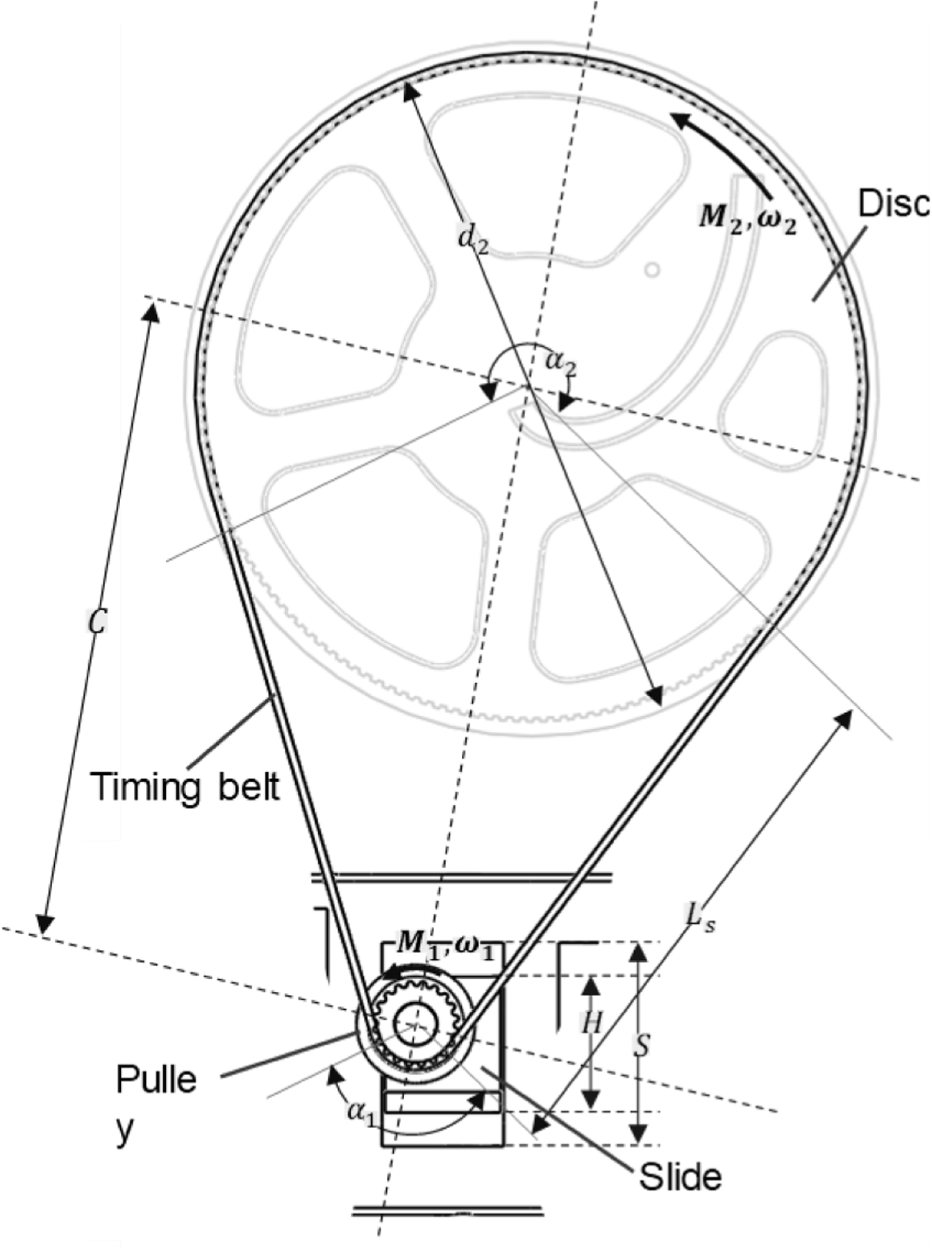
The timing belt drive parameters and dimensions.
| (22) |
| (23) |
| (24) |
To avoid any kind of slippage maintaining proper transmission torque is vital. Under load a difference in belt tension (Te) is created between the two ends of the timing belt as tight (T1) and slack (T2) tension condition. The driver torque (M2) creates the effective tension (Te) in the timing belt. The actuator needs to generate the required torque M2 to drive the discs with M1 torque, which is also dependent on the efficiency η of the motor.
| (25) |
| (26) |
The four discs are actuated with four individual dc micro motors (10 × 12 × 35 mm3, gear ratio 1: 298, 90 rpm). Micro motor is chosen for its small size, which fits our compact design but provides higher torque capability. This motor was also chosen because this motor resembles (in size and function) the MRI compatible piezo electric motor LR80 from PiezoLeg which will be used when testing in future in the MRI room.
The quadrature encoder allows the motor to have 3575 countable event per revolution at the output shaft. Having higher events per count was important to attain higher resolution of the motor movement. Higher resolution of the motor movement allows the disc to rotate in a more precise manner. To control the motor, we used an industrial grade multi axis motor controller (DMC4080 Galil motion controller). DMC4080 controller was chosen specifically since it has eight axis motor control capability and we needed four of them to individually control the four motors. Each axis has its own amplifier to provide the motor power and read the quadrature encoder to execute the controller’s motion command. PID tuning was performed for the motors to ensure smooth motion and to reach its desired position / rotational angle with a smooth movement and optimum error. The controller provides the angle of rotation in terms of number of counts the motor requires to rotate in certain direction considering the pulley and motor turn relationship using Eqs. (17)–(20). This is being repeated for four motors and a certain intersection position is achieved for the two pairs of double disc, which results in certain angulation of the needle guidance.
For rapid prototyping, our custom designed parts were 3D printed with an MRI compatible plastic material (PLA) using Stratasys 3D printer. We used off the shelf parts for the standard components to minimize build time i.e., DC micro motor (Micro Metal DC Geared Motor with quadrature encoder with a gear ratio of 298:1 with 90 rpm at 6 V); Timing belt (MXL Series McMaster 7887K28; 1/8″ width; 0.08′ pitch; 15.2″ outer circle; 190 trapezoidal teeth) and pulleys (MXL Series McMaster 1375K21; 1/8″ width; 08″ pitch; 0.685″ outer diameter; 20 trapezoidal shaped teeth);.These components and the 3D printed parts were assembled to build the robot.
Results
We developed a prototype of the 4-DOF robot (Fig. 5(a), (b) and (c)). The robot is L shaped when viewed from its side and has a dimension of 40 × 110 × 180 (width × length × height) mm3 excluding its bottom extended part. This vertical part houses all the components of the robot excluding the actuators. This additional 50 × 110 × 50 mm3 is added to house the actuators but to keep the overall robot profile minimal. The center of the double-discs is at 120 mm height matching the average height of patients’ prostate at lithotomy position during the procedure from an MRI bed. This allowed us to utilize the bottom 70 mm to house the pulley mechanism, transmission and actuators and kept the working area of the double-disc clean.
Fig. 5.

3D printed prototype along with the mechanical components with its outer dimensions and the full setup for the robotic operation. (a) Isometric view. (b) Top view. (c) Left hand side view. (d) Mechatronic setup for the 4-DOF robot. Components: (1) needle; (2) four discs (D1, D2, D3 and D4); (3) grooved profile; (4) front and rear cover; (5) motor casing; (6) four motors; (7) disc’s lateral support; (8) four timing belts; (9) driving pulley and (10) base.
Fig 6(a) shows the two intersecting grooves created following the profiles (f1 and f2) on the disc and their interaction with the spherical hollow ball. The intersecting grooves creates constant square shape pocket for the hollow spherical ball. The cross section of the groove profile in Fig 6(b) shows how the needle insertion is restricted to only 30° (i.e. ±15°).
Fig. 6.

(a) Perpendicular intersection of the two groves creating a square-shape pocket to firmly hold and allow the hollow spherical ball to move smoothly. (b) Chamfer created on the disc face to accommodate the needle angulation.
Fig 7(a) and (b) shows a probable intersection of the two profiles on the double disc pair. Each intersection generates two different point on each pair of discs by rotating the blue and purple profile. The profiles intersect with each other and generates a grid. The black intersecting grid of profiles are representative of the rotating profile pairs. For Fig 7(a) we have considered symmetrical rotation of each disc (i.e. profile) and deliberately kept the rotation in higher degrees for better visualization. The symmetrical rotation of the disc pair produces regular radial points along the disc in Fig 7(a). Red, green and cyan dashed line shows three representative radial point patterns on Fig 7(a) for better understanding.
Fig. 7.

(a) Intersection grid of profile f1 and f2 when both discs are symmetrically rotated at an interval of π/24. (b) Intersection grid of profile f1 and f2 when one of disc are kept static and other rotates at an interval of π/48. (c) Point cloud created by forward kinematics on the discs and conical works space generated by utilizing inverse kinematics considering 15° constrain to reach certain points (small black sphere at the apex). (d) Point cloud on the insertion plane (i.e. first plane form the direction of needle insertion) and black circular region satisfying the limiting cone.
Fig 7(b) shows non-symmetric rotation of the disc (i.e. profile) which in results can generate intermittent point either any point on the profile or on the disc in between compared to Fig 7(a). Fig 7(c) shows three cones (red, orange and blue) and Fig 7(d) shows their corresponding base circular on the first double disc.
Fig 8 shows the overall workspace of the needle (i.e. the end effector). The reachability of the needle depends on the length of the needle. From the needle length (155 mm) and the radius (40 mm) of the profile we can calculate the 2D workspace from the schematic presented in Fig 8(a). The cyan 3D conical shape in Fig. 8(b) represents 3D workspace and point cloud for the needle tip. This 3D envelope can also be constructed by revolving 2D workspace shown in Fig 8(a). For a certain point Fig. 8(b) shows the possible cone (dark black) for the path planning to reach a random point in the prostate where apex of the cone is the target point, apex angle is ±15° angulation capability of the needle and the circular base (i.e., the entry region of the biopsy needle) is the result of angulation and the perpendicular distance from the target point.
Fig. 8.

(a) Geometric parameters to describe the working envelope of a biopsy needle through our device and the 2D working envelope. (b) 3D envelope generated by revolving the 2D envelope which encompasses the prostate including a probable insertion cone. Spherical black ball, two circular black discs, lneedle, lthickness, lprostate and dcurve represents the prostate, the two double disc pairs, biopsy needle length, thickness of the device, position of the prostate and radius of the profile respectively.
Discussion
Until now US has been the most popular imaging modality to assist with prostate cancer diagnosis despite of its higher false negatives compared to MRI [16]. MRI-guided prostate biopsy has the potential to increase the accuracy of a biopsy with less trials. Recently, MRI- guided biopsy has been the focus of research because of its excellent soft tissue contrast. Despite the superior clinical output, MRI-guided interventions are complex. This paper presents a novel mechanism for 4-DOF needle placement for transperineal prostate biopsy. A robotic design is proposed with four thin discs parallelly stacked together. The results indicate that the four discs with engraved grooves can provide a planar movement for two ball-joints through which the biopsy needle passes. Finally, we have discussed the design and kinematics in details.
In this work, we reported the development of a novel 4-DOF parallel robot needle guidance mechanism for accurate targeting under MRI guidance. We have demonstrated that our mechanism is capable of reaching a target point in a prostate within its working envelope from different insertion points by providing up to ±15◦ of angulation capabilities which can be useful to avoid certain organs/tissues while performing biopsy. We also proposed a path-planning algorithm considering the mechanical constrain posed on the mathematical model for the inverse kinematics. Since our mechanism utilizes four circular disc and engraved profiles to perform the parallel robot manipulation and the discs are peripherally supported, it has more structural rigidity as opposed to the axial support with slimmer profile. Timing belt operated mechanism provided the opportunity to utilize the bottom space for the actuators to offer more operating space for the surgeon. By choosing this non-traditional parallel robotic manipulation we were able to maintain our robot profile similar to the existing manual template guide which makes our device easier to install in the operating environment with minimal procedural adjustment and without compromising the surgeon’s operational area.
We proposed the mathematical model of the forward and inverse kinematics of the 4-DOF mechanism. The mathematical model depends on the function of the profile curve on the disc, the spaces between the discs, the angulation constrain and finally the insertion length of the needle. For forward kinematics the needle’s tip pose is presented as a vector in Eq. (9), the target point presented in Eq. (10) and the needle length limited by the cone with the base angle of 30° and base radius presented in Eq. (21). For inverse kinematics the individual discs’ angles are obtained through Eqs. (11)–(21) and again satisfying the similar cone constrain mentioned above.
The profiles on the discs are perpendicular with each other constantly to ensure the intersecting pockets are square shape. Since we are using spherical balls we want the intersection of the grove to maintain a constant square-shape pocket to accommodate it and maintain constant contact forces (N1 and N2) exerted by the groove faces on the spherical ball at every instance during static equilibrium (Fig. 6(a)). While in dynamic motion the rotary motion of the disc (i.e. profile) creates forces perpendicular to the profile in the direction of the rotation creating a force component which slides the hollow ball inside the intersecting profile..
However, the mechanism is relying on circular discs and the two intersecting profile pairs (f1 and f2) has an intersection at the center of each disc (x = 0, y = 0). Once this point is reached the device reaches a singularity and the motion component at this point is zero at any given time. At this point the hollow balls are not controllable and manipulable.
As our design poses a mechanical constrain to the angulation of the needle, hence not all the solution from the inverse kinematics is feasible. The needle held by our mechanism cannot hold an angle larger than 15° with respect to the disc’s axis of rotation. As discussed in section 2.3 it is vital that the groove designs can accommodate the angular inclination of the needle and stay perpendicular to each other. Therefore, a 15° chamfer was introduced in the groove of the outer face of each double discs shown in Fig. 6(b). Hence, the design allows ±15° of needle angulation.
The angular constraint can be imagined as a cone with a vertex angle of 15°, because the groove cross-sectional profile physically limits angulation of the needle within this range. This constraint controls the movement of the ball joint. The individual movement of the ball-joints are limited by this conical constrain. So, the ball at the needle entry point will be on the base of the cone and the destination point will be its apex. The second ball in-between must fall into the envelope of this cone. Therefore, any path planning must satisfy this idea of cone profile for the two ball joints and the destination point. For path-planning algorithm at every point, the solution to the inverse kinematics Eqs. (11)–(21) of the robot must satisfy this conical envelope. Unless the mechanical constrain will create a singularity for that instance.
For our system, we are able to generate intersecting points in two ways. One is symmetrical rotation of both discs in the same pair or non-symmetric rotation of the each disc. As seen from Fig 7(a) during symmetrical but opposite rotational movement of the disc pair the intersecting points are generated as a radial line going outwards or inwards from the center. The blue arrow in Fig 7(a) shows one representative scenario. All the intersecting points on the blue line can be formulated in this way. The dashed circular pattern can be generated when the disc pairs are stationary with respect to each other, but the pair is rotating in a certain direction. While doing so we may miss points in between the radial lines. To mitigate this and for more precise positioning, we can rotate the two discs in the same pair unevenly. The uneven rotation of the discs can generate points on the profile shown in Fig 7(b) and in between the points compared with the approach shown in Fig 7(a). Therefore, we are able to generate any probable point by manipulating the disc pairs either rotating them symmetrically or by rotating one disc unevenly compared with the other rotating disc of the same pair. These points and profiles have been created by utilizing forward kinematics and Eqs (1)–(20). The intersecting profiles create the point on the plane.
Fig. 7(d) shows the base of the cone produced due to the 15° angulation constrain on the entry plain (double disc intersection). This circular envelope is the area of entry to reach a certain apex of a cone. These cones are probable constraining cones (volumetric space) to reach each small black sphere (i.e. target point) and all the purple points overlapping the base circular area (black circular shade) in Fig. 7(d) are the corresponding entry points to reach the target point. Fig. 7(c) shows the cones produced due to the 15° angulation constrain on the entry plain (double disc intersection). The cone constraint have been created with a combination of forward and inverse kinematics and utilizing Eq. (21).
Workspace is a geometric shape defined as the volume enveloping all possible target reachable by the end effector. For our profile based parallel robot it is a function of the grooved profile, the chamfer angle in the groove, and distance of the front most part of the mechanism from the perineum. The 2D plot in Fig. 8(a) was generated considering the maximum length of the biopsy needle. The 3D point cloud in Fig. 8(b) was generated utilizing maximum needle length by forward kinematics and the cone inside the workspace was generated by considering the geometrical constrain created by the ±15° angulation and earlier discussed cone derived from Eq. (21). Resolution of a system is defined by how far apart the achievable end effector positions are for a system. In our case, the resolution is highly dependent on the actuator resolution and how the individual discs respond to that.
Sterilization is a key consideration for a surgical device. Our current device is subdivided into two parts i.e., motor housing including the motors in the back side and in the front the rest of the part including the motor transmission mechanism and the discs. The front casing is the only part that is being exposed to patient site. We plan to modify the design to make the motor casing part detachable so it can be detached and reused. We plan to make the front portion disposable with mostly 3D printed parts with a variant of plastic or manufacture with MRI compatible reusable materials (e.g., Ultem) and high heat resistance materials which can be autoclavable to sterilize. The overall system can be covered with sterilized sheath so that the motor housing does not become contaminated. The control box will be kept away from the patient; therefore no sterilization is needed for this part.
For the current prototype, we designed and calculated kinematic configuration based on 18 gauge needle, which is a common needle size in transperineal prostate biopsy. However, the guide tube that connects two hollow spherical joints can be fabricated in multiple sizes to accommodate various needles. The current design can accommodate 16–20-gauge needles.
MRI- guided prostate biopsy can be considered a potential candidate since MRI-TRUS fusion technology is more expensive and requires two imaging modalities to be fused together. Therefore, MRI-TRUS fusion is also prone to registration error and is time consuming. It also requires the patient to be in two different imaging facilities. Additionally, due to the lack of MRI compatible robotic device the MRI-guided biopsy is less explored and requires more extensive study to compare its effectiveness. Development of MRI compatible robotic guide such as ours can open the opportunity to perform MRI-guided prostate biopsy study for further comparison. Moreover, MRI compatible robotic device can reduce the patient visits for imaging since the patient will perform imaging and detection of the cancerous tissue from the same MRI machine and on the same setup the robotic device will be able to perform the tissue sampling. This will also reduce the error for multiple image registration since a single registration will be involved which is related to the MRI machine. Increasing MRI machine availability and advancements in MRI imaging techniques together with precise needle guide that can ensure accurate needle positioning could enable a one-stop prostate biopsy solution for patients.
In the future study, the accuracy and MRI compatibility of the prototype will be evaluated in MRI environment to ensure that the unique mechanism can provide accurate needle guidance in MRI bore. Our profile equation involves exponential component therefore when navigating the needle radially inward or outward on the discs plane will require careful inspection and experimentation. The effect of this exponential component will be assessed in our future studies. Current design includes traditional DC motors sharing the same dimension as an MRI compatible piezoelectric motor as a functional prototype. For the MRI evaluation, we will incorporate MRI compatible piezoelectric motors. We will also perform signal to noise ratio (SNR) and image distortion study. Kinematically, the current design has a controllability issue when the needle passes through the center of the double discs, it loses directional friction contact to escape the center position. The shape of the profile and their intersection dictates this and creates a singularity in the mechanism. The future design will address this issue by adding a push mechanism such as adding a compressed spring to provide additional push force to the hollow ball.
Funding
Research reported in this publication was supported by the National Institute of Biomedical Imaging and Bioengineering of the National Institutes of Health under Award Number R15EB030356. The content is solely the responsibility of the authors and does not necessarily represent the official views of the National Institutes of Health.
Nomenclature
- f 1
Grooved profile on the disc
- f 2
Grooved profile on the disc
- t
Parametric parameter
- Rz(θ)
Rotation matrix along z axis
- P 1
Point on mid-plane of disc pair D1 and D2 (x1, y1,0) Coordinates of P1
- P 2
Point on mid-plane of disc pair D3 and D4 (x2, y2, d) Coordinates of P2
Directionl vector from P1 to P2
- P
Target point on the prostate
- l
Needle length
- θ 1
Disc rotation of D1
- θ 2
Disc rotation of D2
- θ 3
Disc rotation of D3
- θ 4
Disc rotation of D4
- l p
Perpendicular distance between the target point and the disc plane
- r c
Radius of the base circle formed by a cone
- d 1
Diameter of the small pulley
- d 2
Diameter of the disc
- α 1
Angle of wrap around the small pulley
- α 2
Angle of wrap around the disc
- C
Distance between the centre of pully and disc
- L
Belt length
- T 1
Tight tension
- T 2
Slack tension
- M 1
Torque on the disc
- M 2
Driver torque
- η
Efficiency of the driver motor
- Te
Effective tension in the timing belt
Footnotes
Declaration of Competing Interest
There is no conflict of interest with our submitted manuscript titled “Kinematic and Mechanical modelling of a Novel 4-DOF Robotic Needle Guide for MRI-guided Prostate Intervention”.
References
- [1].Cancer Facts & Figures 2021: American Cancer Society; 2021. Available from: https://www.cancer.org/research/cancer-facts-statistics/all-cancer-facts-figures/cancer-facts-figures-2021.html. [Google Scholar]
- [2].Caglic I, Breznik S, Matela J, et al. , Lesion targeted CT-guided transgluteal prostate biopsy in combination with prebiopsy MRI in patients without rectal access, Urol. Case Rep 10 (2017) 6–8. [DOI] [PMC free article] [PubMed] [Google Scholar]
- [3].Grummet J, Pepdjonovic L, Huang S, et al. , Transperineal vs. transrectal biopsy in MRI targeting, Transl. Androl. Urol 6 (3) (2017) 368. [DOI] [PMC free article] [PubMed] [Google Scholar]
- [4].Sarkar S, Das S, A review of imaging methods for prostate cancer detection, Biomed. Eng. Comput. Biol 7 (Suppl 1) (2016) 1–15. [DOI] [PMC free article] [PubMed] [Google Scholar]
- [5].Kongnyuy M, George AK, Rastinehad AR, et al. , Magnetic resonance imaging-ultrasound fusion-guided prostate biopsy: review of technology, techniques, and outcomes, Curr. Urol. Rep 17 (4) (2016) 32. [DOI] [PMC free article] [PubMed] [Google Scholar]
- [6].Tempany C, Straus S, Hata N, et al. , MR-guided prostate interventions, J. Magn. Reson. Imaging: Off. J. Int. Soc. Magn. Reson. Med 27 (2) (2008) 356–367. [DOI] [PMC free article] [PubMed] [Google Scholar]
- [7].Li M, Gonenc B, Kim K, et al. , Development of an MRI-compatible needle driver for in-bore prostate biopsy, in: 2015 International Conference on Advanced Robotics (ICAR), IEEE, 2015. [DOI] [PMC free article] [PubMed] [Google Scholar]
- [8].Rothwax JT, George AK, Wood BJ, et al. , Multiparametric MRI in biopsy guidance for prostate cancer: fusion-guided, Biomed. Res. Int 2014 (2014). [DOI] [PMC free article] [PubMed] [Google Scholar]
- [9].Roethke M, Anastasiadis A, Lichy M, et al. , MRI-guided prostate biopsy detects clinically significant cancer: analysis of a cohort of 100 patients after previous negative TRUS biopsy, World J. Urol 30 (2) (2012) 213–218. [DOI] [PubMed] [Google Scholar]
- [10].Dianat SS, Carter HB, Schaeffer EM, et al. , Association of quantitative magnetic resonance imaging parameters with histological findings from MRI/ultrasound fusion prostate biopsy, Can. J. Urol 22 (5) (2015) 7965–7972. [PubMed] [Google Scholar]
- [11].Hong CW, Amalou H, Xu S, et al. , Prostate biopsy for the interventional radiologist, J. Vasc. Interv. Radiol 25 (5) (2014) 675–684. [DOI] [PMC free article] [PubMed] [Google Scholar]
- [12].Hoeks CM, Barentsz JO, Hambrock T, et al. , Prostate cancer: multiparametric MR imaging for detection, localization, and staging, Radiology 261 (1) (2011) 46–66. [DOI] [PubMed] [Google Scholar]
- [13].D’Amico A, Cormack R, Tempany C, et al. , Real-time magnetic resonance image-guided interstitial brachytherapy in the treatment of select patients with clinically localized prostate cancer, Int. J. Radiat. Oncol. Biol. Phys 42 (3) (1998) 507–515. [DOI] [PubMed] [Google Scholar]
- [14].D’amico AV, Tempany CM, Schultz D, et al. , Comparing PSA outcome after radical prostatectomy or magnetic resonance imaging-guided partial prostatic irradiation in select patients with clinically localized adenocarcinoma of the prostate, Urology 62 (6) (2003) 1063–1067. [DOI] [PubMed] [Google Scholar]
- [15].Tilak G, Tuncali K, Song SE, et al. , 3T MR-guided in-bore transperineal prostate biopsy: a comparison of robotic and manual needle-guidance templates, J. Magn. Reson. Imaging 42 (1) (2015) 63–71. [DOI] [PMC free article] [PubMed] [Google Scholar]
- [16].Song S−E, Tokuda J, Tuncali K, et al. , Development and preliminary evaluation of a motorized needle guide template for MRI-guided targeted prostate biopsy, IEEE Trans. Biomed. Eng 60 (11) (2013) 3019–3027. [DOI] [PMC free article] [PubMed] [Google Scholar]
- [17].Li R, Xu S, Bakhutashvili I, et al. , Template for MR visualization and needle targeting, Ann. Biomed. Eng 47 (2) (2019) 524–536. [DOI] [PMC free article] [PubMed] [Google Scholar]
- [18].Tokuda J, Tuncali K, Iordachita I, et al. , In-bore setup and software for 3T MRI-guided transperineal prostate biopsy, Phys. Med. Biol 57 (18) (2012) 5823. [DOI] [PMC free article] [PubMed] [Google Scholar]
- [19].Cunha JA, Hsu I−C, Pouliot J, et al. , Toward adaptive stereotactic robotic brachytherapy for prostate cancer: demonstration of an adaptive workflow incorporating inverse planning and an MR stealth robot, Minim. Invasive Ther. Allied Technol 19 (4) (2010) 189–202. [DOI] [PMC free article] [PubMed] [Google Scholar]
- [20].Chen Y, Squires A, Seifabadi R, et al. , Robotic system for MRI-guided focal laser ablation in the prostate, IEEE ASME Trans. Mechatron 22 (1) (2017) 107–114. [DOI] [PMC free article] [PubMed] [Google Scholar]
- [21].Seifabadi R, Li M, Xu S, et al. , MRI robot for prostate focal laser ablation: an ex vivo study in human prostate, J. Imaging 4 (2018) 140, 11/29. [Google Scholar]
- [22].Fischer GS, Iordachita I, Csoma C, et al. , MRI-compatible pneumatic robot for transperineal prostate needle placement, IEEE/ASME Trans. Mechatron 13 (3) (2008) 295–305. [DOI] [PMC free article] [PubMed] [Google Scholar]
- [23].Patel NA, Azimi E, Monfaredi R, et al. , Robotic system for MRI-guided shoulder arthrography: accuracy evaluation, in: 2018 International Symposium on Medical Robotics (ISMR), IEEE, 2018. [Google Scholar]
- [24].Biswas P, Song S−E, editors. A novel 4-DOF manipulator for MRI-guided transperineal prostate intervention. Image Guided Therapy Workshop; 2020; Virtual. 2020 National Image Guided Therapy Workshop; 2020. [Google Scholar]