Abstract
Background: The hand motor function is lost and activities in daily life (ADLs) are affected due to some illnesses such as stroke and hemiplegia. As a coping way, we present a wearable rehabilitation glove with the bionic actuator for restoring the hand function and the motor control ability lost by stroke patients. Methods: The soft pneumatic bionic actuator (SPBA) is developed on the basis of the research of human hand bone structure and finger joint characteristics and a series of tests are conducted. Besides, we built the rehabilitation glove system based on the proposed SPBAs to verify the availability due to typical gesture, mirror therapy (MT) and grasping experiment for irregular objects. Result: The bending angle of SPBA can reach 260°. The output force of it can reach 5.1N with 0.25 MPa air pressure input. The maximum variance of the bending angle can be concluded at 5.1° in MT. The grasping experiments of the glove worn on the hand or not shows the proposed glove is flexible, the grip force is large and achieve stable grasping of objects. Conclusion: The designed SPBA is satisfied with the requirements of rehabilitation training and the proposed glove restore the normal hand motion of patients in ADLs.
Keywords: Rehabilitation glove, hand rehabilitation, soft actuator, sliding mode impedance control
I. Introduction
Stroke and hemiplegia may cause hand dysfunction due to brain tissue damage. The patient’s activities of daily living (ADLs) are impeded and the living quality is lead to a loss [1]–[3]. Therefore, functional rehab is crucial [4]. In recent years, with rapid integration and development of modern medicine and engineering tech, major strides have been made in exoskeleton tech for hand rehab. The development of wearable hand exoskeleton tech has made it more efficient for hand function therapy [5]–[7].
Numerous groups worldwide have conducted studies on hand rehabilitation robotics with different actuators for restoring muscle and nerve function of activities in daily life (ADLs) [8]–[11]. Most hand rehabilitation devices are implemented with pneumatic [12], motors [13], [14] and bionic actuators [15]–[18]. The ExoHand from Festo is driven by 8 double-acting Cylinder, which can realize finger flexion and extension movement [19]. A closed feedback loop is established based on the brain-computer interface of it. YAP et al. developed the ExoGlove consist of variable stiffness pneumatic actuator therapy hand functions through different stiffnesses in different positions [20]. The Gloreha developed from Italy driven with 5 motors, different meticulous motions can be completed through 3D animations with the glove. The novelty of it is the sensory stimuli such as audio and video are combined with hand movements to promote functional recovery [21]. Satoshi Ueki et al. design a hand exoskeleton. 3 motors are designed for each finger to complete metacarpophalangeal (MCP) and middle joints active [22]. The rehabilitation exoskeleton driven by a cylinder and a motor is a typical rigid exoskeleton device, which has disadvantages such as heavy weight, poor flexibility, and poor range of motion (ROM) and the objects may deformed or damaged fragile due to its large grasping force. With bionic actuator, a new way for the design of robotic rehabilitation glove is provided [23]–[25]. A tendon-driven self-pumping bidirectional soft actuators proposed by Ren and Li et al. that can bend with the gas pressure changed [26]. Tadano et al. proposed a rehabilitative hand with bidirectional motion, each finger has a linear pneumatic muscle with two degrees of freedom [27]. The HERO glove proposed by Yurkewich et al. embeds artificial tendons in the fingers for stable grasping of daily objects through stretching and flexing fingers motions [28]. NASA developed a multi-degree-of-freedom robotic hand based on an artificial joint [29].
In summary, despite these efforts, some problems with hand rehabilitation devices remain unsolved [30], [31]. For instance, the hand rehabilitation exoskeletons focus on function realization but ignore the user-device interaction during different motions. In addition, the mass of glove should be taken into consideration for portable and motion control as a wearable device.
Here, we aim at the rehabilitation needs of patients with hand hemiplegia, a fiber-reinforced soft pneumatic bionic actuators (SPBAs) have been proposed and a rehabilitation glove is developed based on it. It has the characteristics of simple structure and easy manufacturing. Its output terminal contact force is relatively large and different actuation postures can be output based on different winding fiber angles on the periphery. The rest of the paper is organized as follows: the design and production of the bionic actuator is described in Section II. In Section III, the performance testing of the actuator has been conducted. Section IV design the rehabilitation glove system and in Section V a series of protype training confirmed the effectiveness of rehabilitation gloves including typical rehabilitation gesture, mirror therapy and grasping experiment. Finally, Section VI concludes this article and discusses the comparisons with previous works and some improvements that can be optimized in future work.
II. Design of Soft Bionic Actuator
This section describes the design of the proposed soft actuator with reference from multiple previous studies [32]–[35]. Firstly, the bending principle of the SPBA is introduced. Then, the characteristics of bone and fingers are considered to design the bionic structure of the actuator. Finally, the dimensions are determined after analyzing different motion characteristics and optimizing parameters. In addition, the design of actuator and mold provide the basis for the rehabilitation glove.
A. Structure Design
As a wearable device, the first design requirement of the soft actuator is to fit the hand to avoid any pain and fatigue. The safety and comfort of the wearer is guaranteed through optimal design of the mechanical and control system that the driven range has to be ensured within the maximum range of hand natural motion.
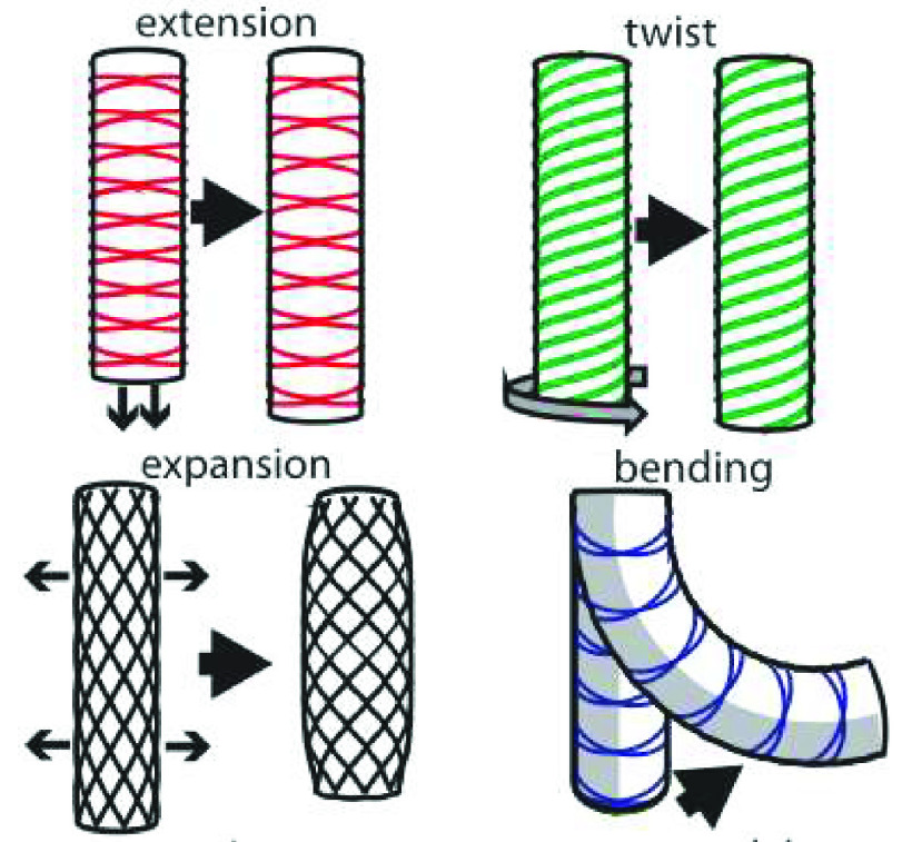
The soft bionic actuators can be divided into Pneumatic Networks actuators and Fiber-Reinforced actuators according to the internal chamber structure. The principle of the Pneumatic Networks actuator is shown in Fig 1 [32]. It is fabricated with corrugated structure, which is difficult to manufacture and poor versatility. The improved Fiber-Reinforced is currently used more frequently due to the characteristics of simple structure and easy manufactured. It has large tip force and different actuation postures can be output based on different outer periphery winding fiber angles as shown in Fig 2 [33]. The mechanism is designed based on Fiber-Reinforced bionic actuator after comprehensive comparison.
FIGURE 1.
Pneumatic Networks actuator and the working principle.
FIGURE 2.
Different actuation postures due to different winding angle of fiber line in fiber-reinforced actuator.
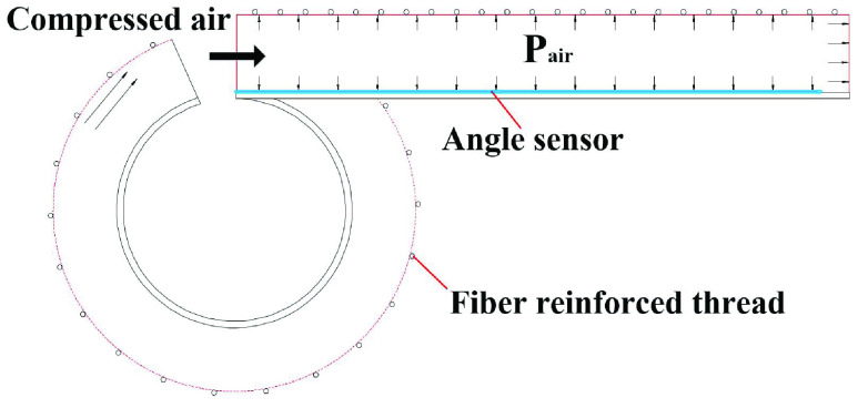
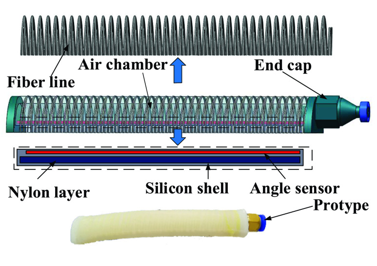
The structural design of soft pneumatic bionic actuators (SPBAs) is carried out based on the hand bone structure and joint characteristics. The cross-sectional shape as an important factor affecting the output of the actuator is firstly considered in the design. It has been concluded due to the previous study that the actuator with cross-sectional shape semicircular can output a larger bending angle than other cross-sectional shape with the same air pressure [33]. Therefore, the semi-circular is adopted to the chamber structure of the actuator. The helical fiber is uniform winding on its surface, a nylon confinement layer is set at the bottom, and a flexible angle sensor is embedded between them. Radial expansion of the actuator is limited with the fiber line, and bottom elongation is limited with the non-extensible nylon layer. The actuator is bent with the strain difference between the chamber and the confinement when the pressure input [33]. The bending principle of the actuator with continuously pressurized through the inlet is shown in Fig 3.
FIGURE 3.
The bending principle of the bionic fiber-reinforced actuator.
It can be known that the output performance of the soft actuator is importantly affected by the fiber line based on the above bending principle. The single helix fiber line is prone to torsion through referring to the relevant literature, comparing the influence of the different winding methods of the double helix and the single helix fiber line on the bending of the actuator. Therefore, the double helix structure is selected for the outer circumference of the actuator due to the characteristics of simple and reliable structure, fast response and high power as shown in Fig 4.
FIGURE 4.
Schematic diagram of the structural composition of the fiber-reinforced soft pneumatic bionic actuator.
B. Geometrical Parameter Analysis
The geometrical parameters influence the performance of the actuator fall into five categories: the material of the silicon rubber, the diameter of the fiber line, the winding angle, the thickness of the wall, and the diameter of the chamber. The material and structural property is necessary to be comprehensively analyzed and evaluated to obtain specific parameters of the actuator.
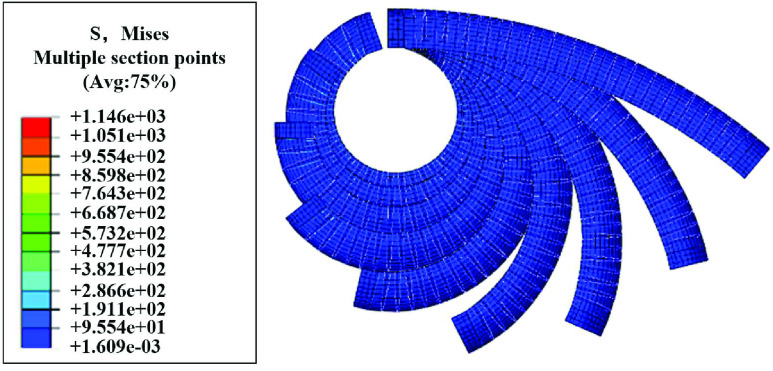
In the process of analysis, the actuator radius a, wall thickness t and length L are transformed for comparison, and the other parameters are kept unchanged. The maximum bending angle of the actuator under certain pressure conditions as the standard to measure the driving performance. The deformation analysis of the actuator under different pressure is shown in Fig 5.
FIGURE 5.
The deformation result with finite element model simulation.
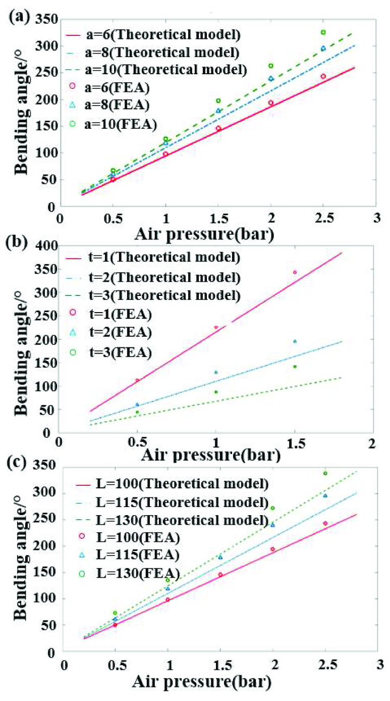
The theoretical deformation equation of the air pressure and the bending angle is obtained based on the strain energy function model of the nonlinear hyper elastic material. The chamber radius a, wall thickness t and length L of the actuator are changed respectively for the improvement of the bending performance of the actuator. The actuation performance of the actuator is comprehensively analyzed between the theoretical model and FEA, and the results are shown in Fig 6.
FIGURE 6.
Mathematical model and finite element simulation of influence on bending angle (a) chamber radius a. (b) wall thickness t. (c) length L.
The bending angle of the theoretical model is larger than the result of FEA with the same actuation pressure. The error is mainly from the linearization of the NH model in the theoretical analysis and the expansion effect of the elastomer simulated by the finite element model. It is shown in the result that the chamber radius and length are not obvious to affect the bending performance of the actuator, the larger the parameter, the better the bending performance. However, the actuation performance of the actuator is significantly improved with the wall thickness reduced. The stability and fatigue would be affected due to the wall thickness in the actual application and fitting of the actuator and finger. The structural parameters of the integral actuator are decided in TABLE 1.
TABLE 1. Actuator Size Parameters.
| Total actuator length L(mm) | Actuator radius a(mm) | Chamber radius r(mm) | chamber wall thickness t(mm) | Actuator bottom edge thickness b(mm) | Winding wire diameter r0(mm) | Winding spacing s(mm) |
|---|---|---|---|---|---|---|
| 115 | 10 | 16 | 2 | 2 | 0.4 | 3.6 |
C. Fabrication of Soft Actuator
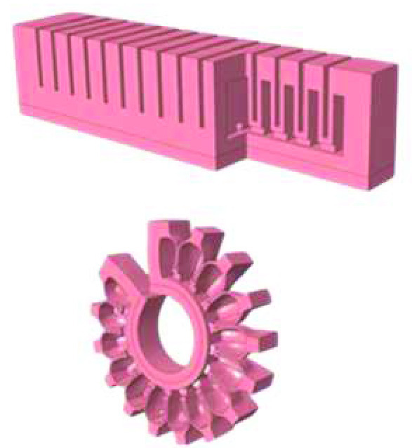
The soft actuator designed is a hollow cylindrical with small size, high precision of local size and high requirement of surface roughness. Additive Manufacturing (AM) technology is adopted for fabricating the soft actuator benefited from the convenience of manufacturing complex structures. Photosensitive resin is chosen as the mold material due to its smooth and lightweight. ECOFLEX 0030 silicone rubber is chosen as the material for the actuator.
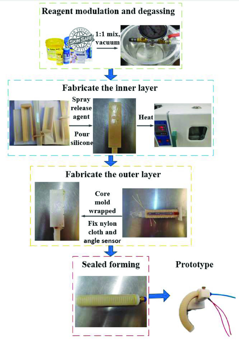
The preparation of the actuator can be divided into four parts: (a) reagent modulation and degassing;(b) fabricate the inner layer;(c) fabricate the outer layer;(d) Seal forming. The process of manufacturing the actuator is completed at temperature 25°C and the flow is shown in Fig 7.
-
Step (a):
The A/B parts of ECOFLEX 0030 are mixed and stirred equally (A:B=1:1) and degassed in vacuum to no obvious bubbles.
-
Step (b):
The degassed silicone is poured into the inner layer mold and is heated in an oven for 45 minutes and static 3 hours at 75°C, the mold needs to be pre-sprayed with a release agent.
-
Step (c):
The cured segment and the main actuator is taken out. 4–5 layers of preservative film are wrapped on the core mold to fix the inner layer. The nylon layer is stuck to the bottom, the Kevlar fiber thread is then entangled based on the wire groove and the angle sensor is fixed in the middle surface of the nylon layer. The step (b) is repeated with the outer layer mold to complete the preparation of the outer layer of the actuator.
-
Step (d):
The end caps are Additive Manufacturing with Future 8000 photosensitive resin to fixed and sealed the actuator.
FIGURE 7.
Fabrication process of fiber-reinforced soft pneumatic bionic actuator.
III. The Performance Test of Bionic Actuator
In this section, the bending angle and tip force experiments are conducted to test the actuation performance of the actuator designed. The feasibility of building a rehabilitation glove system based on the proposed SPBA is thus proven.
A. Bending Angle Experiment
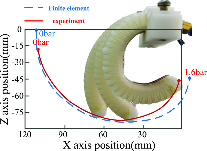
In order to confirm the validity and consistency of the finite element analysis for actuator bending angle, the actuator is bent by increasing the pressure continuously. The bending angle is recorded every 0.12 bar with the pressure varying from 0.60 bar to 1.8 bar as shown in Fig 8.
FIGURE 8.
The bending angle and end trajectory of the actuator with different air pressure.
It is shown that the bending angle of the actuator at low pressure is basically consistent with the results of finite element through comparing and analyzing the relationship between pressure input and actuator bending angle from the experiment. The small error of angle exists between the finite element analysis and experiment under the high pressure due to the expansion effect of the elastomer, action of gravity and other uncontrollable factors. In general, the experimental results and finite element model are accordant, showing this analysis scheme has strong correctness in the design of soft pneumatic bionic actuator.
B. Contact Force Test
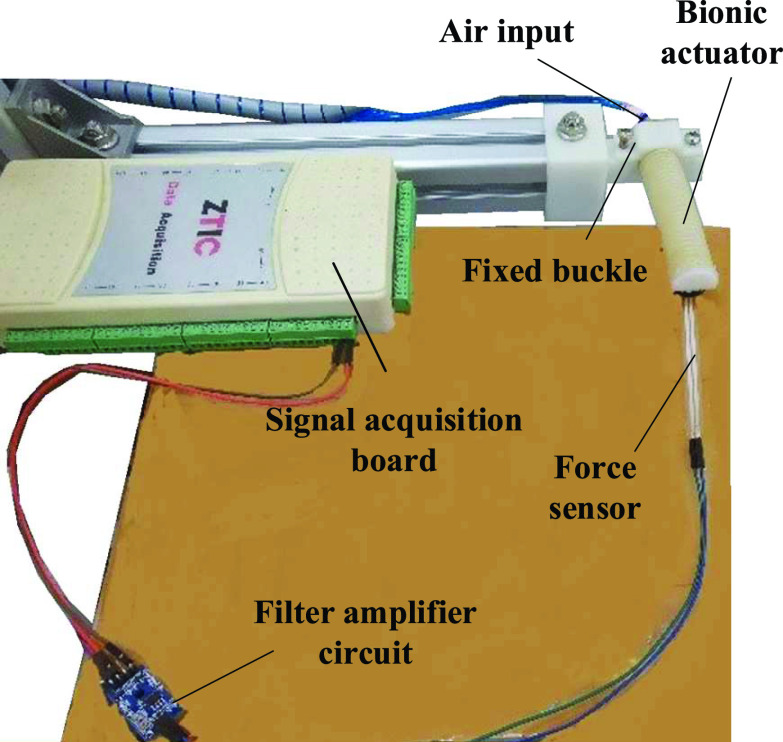
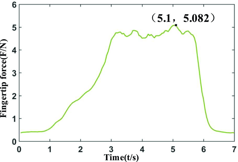
The experiment of contact force test is built as shown in Fig 9 to evaluate the ability of the proposed actuator. The actuator is horizontal arranged, the side of proximal cap is fixed and clamped, and the fingertip is fixed to a film pressure sensor for measuring the fingertip output force. The chamber is pressurized from 0 to 0.2MPa, the signal of the pressure sensor is filtered and amplified, transmitted to the host computer with the acquisition card. Fig 10 shows the contact force by the tip of the actuator.
FIGURE 9.
Contact force test platform for the distal tip of the fiber-reinforced soft pneumatic bionic actuator.
FIGURE 10.
The result of contact force response for the actuator with: 115-mm length, 10-mm radius, 2-mm wall thickness.
It is shown from the result of Fig 10 that the maximum output force at the end of the actuator is about 5.1N. It is shown from the result of Fig 10 that the maximum output force at the end of the actuator is about 5.1N. Combine with previous studies and our own findings, most objects in daily living (e.g. a bottle of water or a fruit, picking up a book etc.) do not weigh more than 1.3kg, which means that each actuator of the rehab glove needs to provide a contact force of about 5N [36]. Therefore, it is proven that the force provided from the actuator meets the requirement for supporting the finger for rehabilitation.
IV. The Design of Rehabilitation Glove
In this section, the rehabilitation glove and its control system are designed based on the needs of hand rehabilitation training and the bionic actuator designed above.
A. Rehabilitation Glove Prototype Based on SPBAs
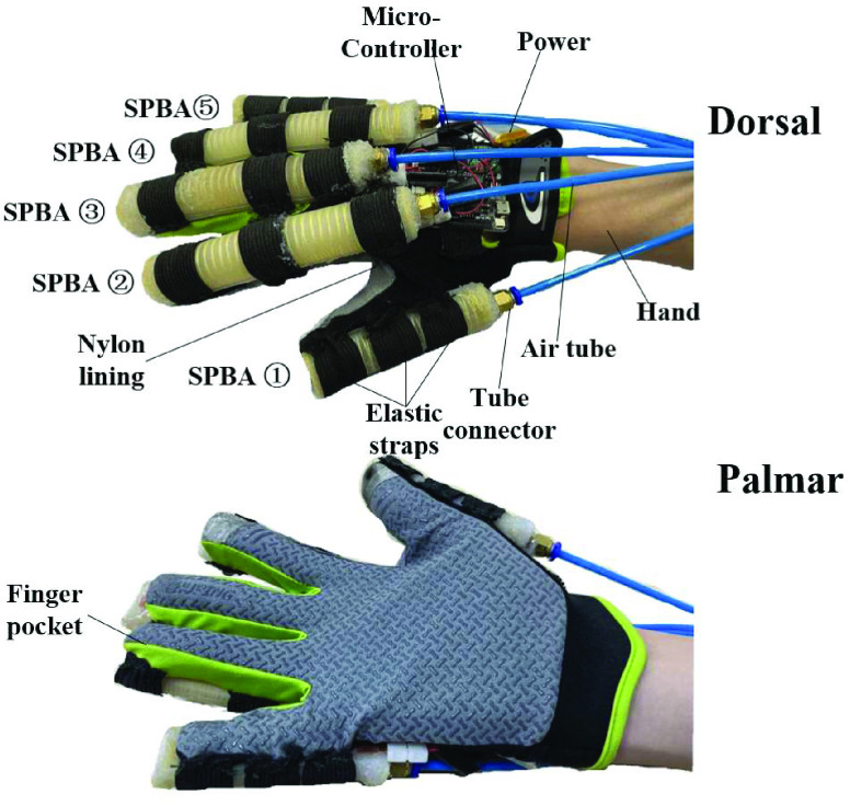
The feasibility of the proposed SPBAs has been verified in section III, a rehabilitation glove system is constructed based on it. The proposed glove consists of two different lengths of actuators due to the differences in finger lengths. Actuators are mounted on the dorsal of fingers to actuate hand achieve the rehabilitation movement. The actuator of each finger is fixed, the micro-controller and its power are fixed on the back of the glove. The glove protype is shown in Fig 11.
FIGURE 11.
Rehabilitation glove based on SPBAs.
An error in the collected sensor signal may be caused and the control accuracy may be affected due to the sliding between the fingers and the actuators. In addition, the arrangement of the actuators should conform to the human biology laws for the free of flexion and extension movement.
B. Control System and Method Design
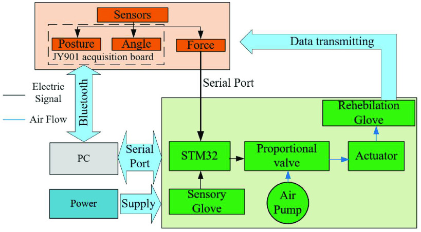
In this paper, compressed air is the power source of actuator and controls them to work independently together based on the data collected from multiple sensors. The control system consists of the PC, power supply module, Sensor acquisition module, pump, ITV0030-2BL Electric proportional valve and STM32F103ZET6 controller. The control system of the rehabilitation glove can be seen in Fig 12. The joint angle and hand posture information of rehabilitation glove is collected through the JY901 acquisition board with sample frequency 20HZ and transmitted to the PC based on the RF-BM-S02 Bluetooth module. Besides, the contact force of rehabilitation glove collected by the force sensor and the bending angle collected by the sensory glove are transmitted to the PC with serial port. The data is displayed in real-time on PC and the training mode which is preprogrammed with the desired trajectory sent to the STM32 controller. The training mode signals from PC are parsed by the STM32 controller. The movement paraments are obtained to control each proportional valves with analogy voltage signal, which further controls the working pressure of each actuator.
FIGURE 12.
Control system of the rehabilitation glove.
The grasping force of fingers is necessary to be controlled for achieving grasp stably with the glove worn. It is difficult to control the grasping force due to the lightweight of the objects in daily life. Fortunately, the Impedance control has a certain resistance to external force and can avoid the interference of it. The position-based adaptive sliding mode impedance control algorithm is selected to control the grip force. The force deviation is used as the input of the target impedance, and the amount of obtained position correction and the preset reference position are used as the desired position, to achieve reliable follow-up of finger grip.
The impedance model of the dynamic between the expected grasping force of a single finger and the finger position is:
 |
where,
 ,
,
 are respectively the target impedance inertia matrix, target impedance damping matrix, and target impedance stiffness matrix.
 are respectively the desired and actual position of the finger.
 is the desired contact force.
 is the actual contact force.
The error of grasping force
 is used as the actuate of the target impedance model to achieve the effective follow-up of the grasping force. The rehabilitation glove has only one degree of freedom, so the target impedance can be simplified as:
 |
where,
 ,
,
 ,
,
 are respectively the Inertia coefficient, damping coefficient and stiffness coefficient.
The target impedance of finger in the frequency domain can be Laplace transformed into the complex-frequency-domain as:
 |
where, s is the complex variable in the complex-frequency-domain.
Therefore, the finger position correction amount is:
 |
The target impedance model for the position-based finger is:
 |
Equation (5) can be further written as follows:
 |
where,
 is the Undamped natural frequency,
 is the Damping ratio of the control system,
 ,
,
 .
.
The dynamic performance of the finger grasping changes with the change of the damping ratio and natural frequency of the system. The overshoot of the system decreases due to the increase of damping value, and the steady-state error decreases due to the decrease of stiffness value. The selected impedance parameters should meet the conditions as:
 |
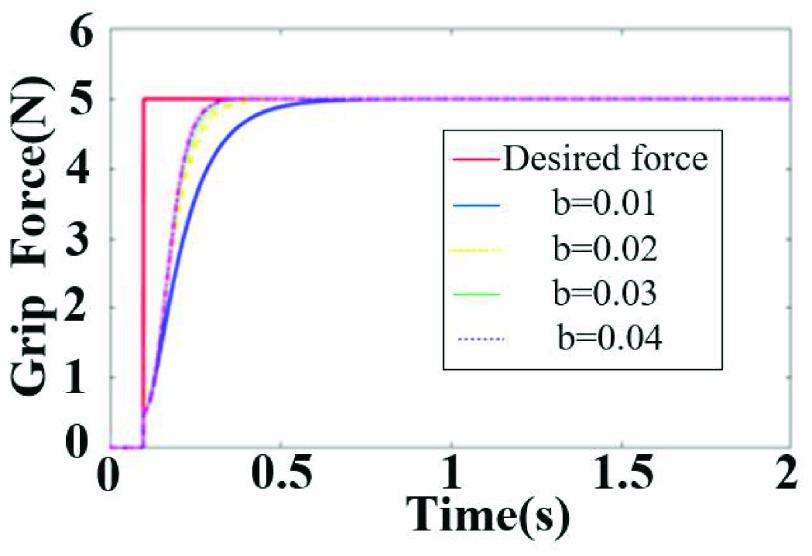
A controller model is built for grip force control simulation. Fig 13 shows the control effect of different damping coefficients on the grasping force following when the expected grasping force is abruptly changed. It can be seen that as the damping coefficient increases, the grip force following is better, and the glove can grasp objects stable based on the adaptive sliding mode impedance control algorithm.
FIGURE 13.
Simulation diagram of the effect of damping parameters on force tracking.
V. Rehabilitation Training Test
This chapter implement a series of experiments with young healthy subject to evaluate the validity and the stability of the proposed rehabilitation glove system. Any experiments are repeated at least three times and presented with average and general results.
A. Typical Rehabilitation Gestures
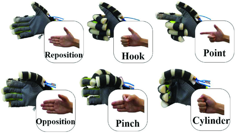
The typical gestures of hand robots include the complete grasping classification method and the single degree of freedom classification method, but both of them are not suitable for ADLs. The former requires complex equipment, while the latter ignores the lateral shrinkage of the grasp during the grasping and evaluation. The gesture classification method that covers 85% of the grabbing actions in ADLs is proposed for it and a typical rehabilitation gesture experiment is conducted as shown in Fig 14.
FIGURE 14.
Typical rehabilitation gesture with reposition, hook, point, opposition, pinch, cylinder.
It can be seen that all of the six typical gestures proposed can be supported with the designed rehabilitation glove worn. The extensor, flexor and lateral tendons of the fingers are effectively trained based on the above methods.
B. Mirroring Therapy Test
The mirror therapy (MT) facilitates aiming at the rehabilitation treatment during the recovery stage of hemiplegia is proposed for finger motor training with typical gestures. The sensory glove is the key component for mirror therapy. It includes multiple sensors to collect the angle and posture information of hands for gesture recognition. A series of gestures are preset on the host computer then choose the corresponding gesture to mirror training. In addition, the angle error of the sensory glove and rehabilitation glove are saved to provide the original data for the subsequent evaluation of rehabilitation training.
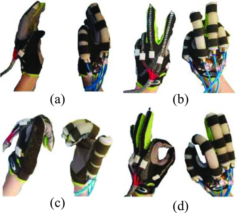
The sensory glove and rehabilitation glove are worn respectively with left and right hands during the mirroring experiment. The hand with sensory glove is active, and the remaining relaxed. The action is converted into a voltage signal as the input source of the controller when the active hand to do a rehabilitation gesture. The rehabilitation glove is driven to complete the same gesture based on it. The gestures of mirror therapy are shown in Fig 15, the action a-d includes common gestures of “RELAX”, “VICTORY”, “FIST” and “OK”. The finger angle and error during the mirror training process are shown in Fig 16.
FIGURE 15.
Training result for mirror therapy test (a) RELAX. (b) VICTORY. (c) FIST. (d) OK.
FIGURE 16.
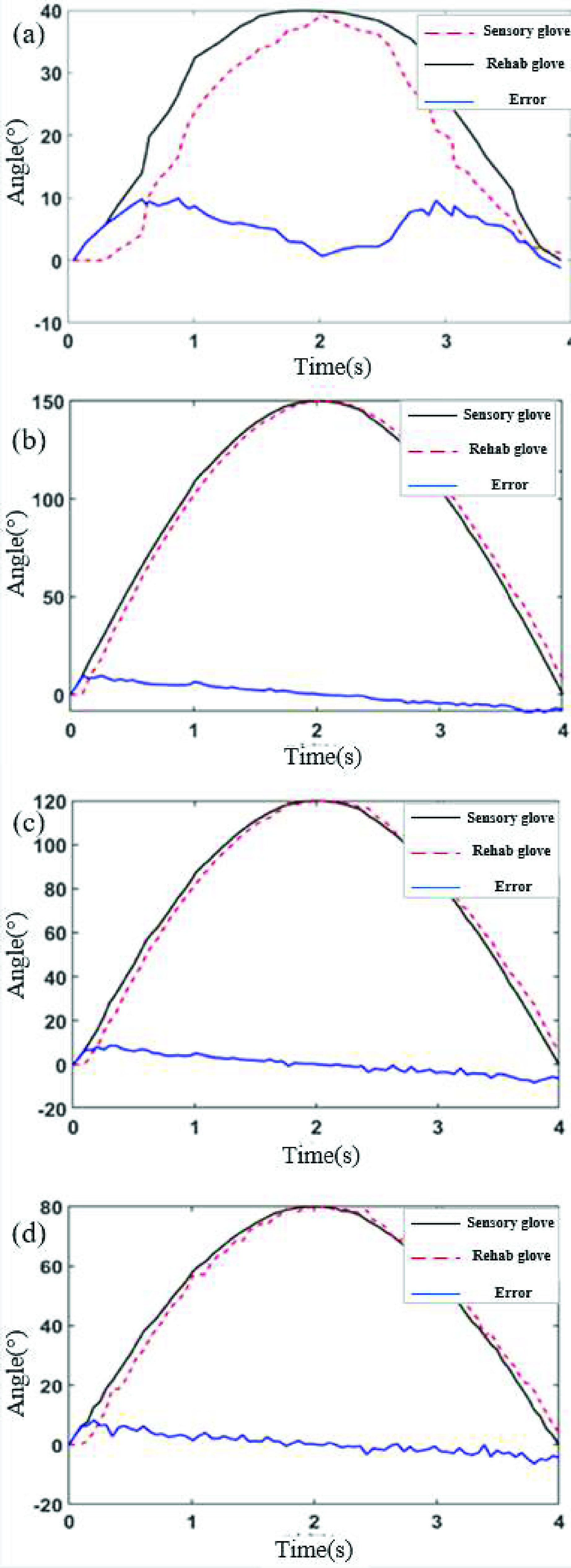
Bending angle and error in the mirroring therapy test. (a) RELAX thumb. (b) VICTORY little finger. (c) FIST middle finger. (d) OK index.
The angle error and variance of the mirror therapy are analyzed to evaluate the effect accurately. The maximum errors of the fingers in the four movements of training are respectively 5.8°, 9.5°, 8.6° and 8.3°, and the maximum variances are respectively 3.5°, 5.1°, 4.4° and 3.3° after processing the collected data. The control accuracy of system mirror therapy can be verified to meet the requirement based on it. The bending ability of index, middle, and ring fingers are better than the thumb and little finger. Besides, it is shown in Fig 16. that the angle of the rehabilitation glove has a little lag compared with the sensory glove and small errors are incurred within the safe angle range at the beginning and the end. Therefore, the rehabilitation glove can be completed well the mirror therapy that the gesture based on the sensory glove.
C. Grasping Test of Rehabilitation Glove
In effort to demonstrate the grasping ability of the rehabilitation gloves proposed without wearer perturbations. The grasping test is conducted with the glove not wearing on the hand as shown in Fig 17. The experiment is completed with an easy grasp columnar object and the pressure for each finger is set through pre-experiment.
FIGURE 17.
Grasping test of rehabilitation glove without the glove wearing on the hand.
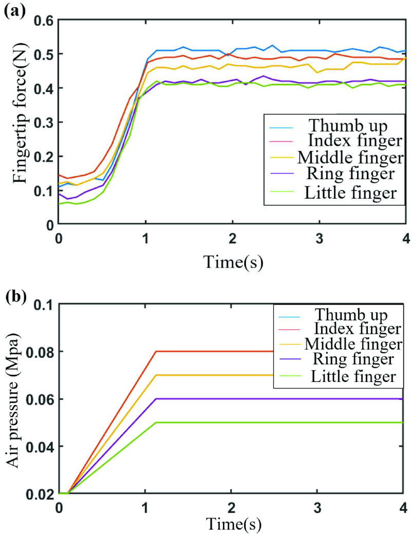
The tip force of fingers and the air pressure of the proportional valve is collected during the experiment for analyzing the control ability quantitatively. The results of each group that can show the average condition have been selected and are presented in Fig 18.
FIGURE 18.
Fingertip force and air pressure of the rehabilitation glove without wearing on the hand (a) fingertip force, (b) air pressure.
It can be seen in Fig 18 that a pressure of 0.02MPa is preset for each finger to remain a certain gesture and then increase the pressure linearly. The pressure of finger is 0.07 MPa for the thumb, 0.08 MPa for the index finger, 0.07 MPa for the middle finger, 0.06 MPa for the ring finger, and 0.05 MPa for the little finger. The average fingertip force of fingers is respectively 0.51N, 0.49N, 0.47N, 0.41N and 0.40N. The objects can be gripped firmly with the glove not worn on the hand. It is proven that the good motion control and sufficient contact force are supposed by the glove in daily grasping.
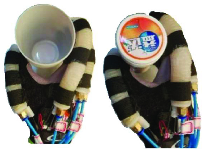
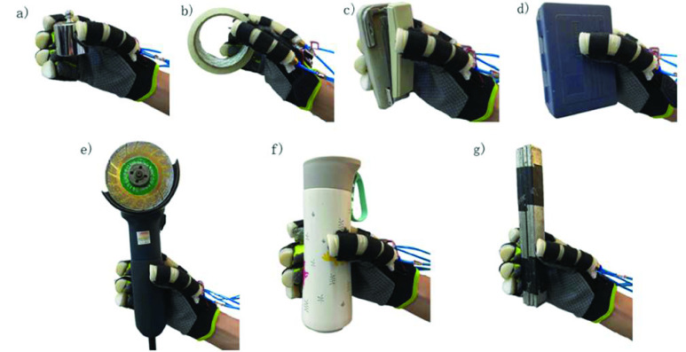
The grasping experiment with a series of daily objects is conducted to further verify the practicability of developed rehabilitation glove. The rehabilitation gloves are worn on the right hand of the subject and muscles are kept relaxed. The corresponding actions are completed due to the glove SPBAs. The forearm extensor muscles bioelectric signals of the subject is stimulated with the action of the distal joints and the high flexor tension of the arm is further relieved. The motor control ability of hand is trained and restored based on it. Several commonly daily objects are selected to test the grasping of rehabilitation glove as shown in Fig 19.
FIGURE 19.
Grasping experiment with the glove worn: a) weight, b) tape, c) stapler, d) box, e) chainsaw, f) water cup, g) iron nuggets, and the subject is wearing the proposed rehabilitation glove.
It can be seen from the experiment that the designed glove is deformed initiative due to the different periphery shape of objects. The gripping state is stable and has large gripping force without dropping off. Therefore, the proposed glove system is suitable for assisting patients with muscular disorders in daily life.
VI. Discussion and Conclusion
In this paper, we proposed a glove system for hand rehabilitation with the fiber rein-forced soft pneumatic bionic actuator. The device is able to assist finger to complete flexion and extension movement in order to facilitate hand training. The glove utilizes SPBA that is made from silicone rubber with the geometrical parameters of length 115mm, radius 10mm and chamber wall thickness 2mm. A series of experiments as typical gesture, mirror therapy and grasping on a healthy participant in our laboratory are conducted to evaluate the performances of the glove. The extensor, flexor and lateral tendons are effectively trained with the typical gesture. The error and variance of the bending angle in mirror therapy is respectively under 9.5° and 5.1°, which could implement mirror follow motion. The contact force of fingertip is about 0.40N t0 0.50N with the glove not worn, which is enough to grasp the objects firmly. The glove with worn could assist the wearer grasping objects in different periphery shapes without dropping off. It is shown from the results that the rehabilitation glove actuated by SPBAs can complete continuous training and have the function of restoring hand movement and control ability which strengthen the coordinated voluntary movement of wearer.
It is shown with the characterization results that the rehabilitation glove proposed with the SPBAs has better adaptability based on the unique biomimetic structures and materials, as compared to previously developed rehabilitation glove with rigid transmission. Although the structural design and preliminary experiments of the rehab glove have made good progress, several limitations of freedom of movement and force feedback still exist with it. In general, it’s also a great device in the translational engineering in health and medicine for hand movement disorders.
For future work, it is planned to follow points: firstly, the structure of actuator would be optimized based on human hands for the freedom to complete radial/ulnar deflection and circular motion to achieve the function of coordinated and coupling motion. At the same time, the contact force and internal stress could be optimized through establishing a theoretical model of the actuator and combining the effects of different structural parameters with the material for better performance. Besides, each joint of fingers as MCP, PIP, IP require complete sensing array for more force feedback during the glove worn. The action intention can be identified more accurately depending on it and the adaptive control can be achieved better due to it. The experiments to stroke patients with spasticity should be conducted in the future based on the optimized device.
Funding Statement
This work was supported in part by the National Natural Science Foundation of China under Grant 51205182, in part by the Six Talent Peaks Project in Jiangsu Province under Grant JXQC-015, in part by the Key Research and Development Plan of Jiangsu Province under Grant BE2019724, and in part by the 2022 Graduate Student Science and Technology Innovation Fund of Nanjing Institute of Technology under Grant TB202217018.
References
- [1].Sisto S., Forrest G., and Faghri P., “Technology for mobility and quality of life in spinal cord injury [analyzing a series of options available],” IEEE Eng. Med. Biol. Mag., vol. 27, no. 2, pp. 56–68, Mar. 2008, doi: 10.1109/EMB.2007.907398. [DOI] [PubMed] [Google Scholar]
- [2].National Spinal Cord Injury Statistical Center. (2017). Spinal Cord Injury Facts and Figures at a Glance. [Online]. Available: https://www.nscisc.uab.edu/Public/Facts%20and%20Figures%20-%202017.pdf [Google Scholar]
- [3].Benjamin E. J.et al. , “Heart disease and stroke statistics-2018 update: A report from the American Heart Association,” Circulation, vol. 137, no. 12, pp. 67–492, 2018. [DOI] [PubMed] [Google Scholar]
- [4].Li M., Xu G., Xie J., and Chen C., “A review: Motor rehabilitation after stroke with control based on human intent,” Proc. Inst. Mech. Eng. H, J. Eng. Med., vol. 232, no. 4, pp. 344–360, 2018. [DOI] [PubMed] [Google Scholar]
- [5].Correia C.et al. , “Improving grasp function after spinal cord injury with a soft robotic glove,” IEEE Trans. Neural Syst. Rehabil. Eng., vol. 28, no. 6, pp. 1407–1415, Jun. 2020, doi: 10.1109/TNSRE.2020.2988260. [DOI] [PubMed] [Google Scholar]
- [6].Sheng B., Zhang Y., Meng W., Deng C., and Xie S., “Bilateral robots for upper-limb stroke rehabilitation: State of the art and future prospects,” Med. Eng. Phys., vol. 38, no. 7, pp. 587–606, Jul. 2016. [DOI] [PubMed] [Google Scholar]
- [7].Pacchierotti C., Sinclair S., Solazzi M., Frisoli A., Hayward V., and Prattichizzo D., “Wearable haptic systems for the fingertip and the hand: Taxonomy, review, and perspectives,” IEEE Trans. Haptics, vol. 10, no. 4, pp. 580–600, Oct. 2017, doi: 10.1109/TOH.2017.2689006. [DOI] [PubMed] [Google Scholar]
- [8].Feng M., Yang D., and Gu G., “High-force fabric-based pneumatic actuators with asymmetric chambers and interference-reinforced structure for soft wearable assistive gloves,” IEEE Robot. Autom. Lett., vol. 6, no. 2, pp. 3105–3111, Apr. 2021, doi: 10.1109/LRA.2021.3062588. [DOI] [Google Scholar]
- [9].Butler N. R., Goodwin S. A., and Perry J. C., “Design parameters and torque profile modification of a spring-assisted hand-opening exoskeleton module,” in Proc. Int. Conf. Rehabil. Robot. (ICORR), Jul. 2017, pp. 591–596, doi: 10.1109/ICORR.2017.8009312. [DOI] [PubMed] [Google Scholar]
- [10].Chen Y., Tan X., Yan D., Zhang Z., and Gong Y., “A composite fabric-based soft rehabilitation glove with soft joint for dementia in Parkinson’s disease,” IEEE J. Transl. Eng. Health Med., vol. 8, pp. 1–10, 2020, doi: 10.1109/JTEHM.2020.2981926. [DOI] [PMC free article] [PubMed] [Google Scholar]
- [11].Takahashi N., Furuya S., and Koike H., “Soft exoskeleton glove with human anatomical architecture: Production of dexterous finger movements and skillful piano performance,” IEEE Trans. Haptics, vol. 13, no. 4, pp. 679–690, Oct. 2020, doi: 10.1109/TOH.2020.2993445. [DOI] [PubMed] [Google Scholar]
- [12].Yun S.-S., Kang B. B., and Cho K.-J., “Exo-glove PM: An easily customizable modularized pneumatic assistive glove,” IEEE Robot. Autom. Lett., vol. 2, no. 3, pp. 1725–1732, Jul. 2017, doi: 10.1109/LRA.2017.2678545. [DOI] [Google Scholar]
- [13].Sandoval-Gonzalez O.et al. , “Design and development of a hand exoskeleton robot for active and passive rehabilitation,” Int. J. Adv. Robotic Syst., vol. 13, no. 2, p. 66, Mar. 2016, doi: 10.5772/62404. [DOI] [Google Scholar]
- [14].Gabardi M., Solazzi M., Leonardis D., and Frisoli A., “Design and evaluation of a novel 5 DoF underactuated thumb-exoskeleton,” IEEE Robot. Autom. Lett., vol. 3, no. 3, pp. 2322–2329, Jul. 2018, doi: 10.1109/LRA.2018.2807580. [DOI] [Google Scholar]
- [15].Kang B. B., Lee H., In H., Jeong U., Chung J., and Ch K., “Development of a polymer-based tendon-driven wearable robotic hand,” in Proc. IEEE Int. Conf. Robot. Autom. (ICRA), May 2016, pp. 3750–3755, doi: 10.1109/ICRA.2016.7487562. [DOI] [Google Scholar]
- [16].Cianchetti M., Laschi C., Menciassi A., and Dario P., “Biomedical applications of soft robotics,” Nature Rev. Mater., vol. 3, pp. 143–153, May 2018. [Google Scholar]
- [17].Zhang J.et al. , “Robotic artificial muscles: Current progress and future perspectives,” IEEE Trans. Robot., vol. 35, no. 3, pp. 761–781, Jun. 2019, doi: 10.1109/TRO.2019.2894371. [DOI] [Google Scholar]
- [18].In H., Kang B. B., Sin M., and Cho K.-J., “Exo-glove: A wearable robot for the hand with a soft tendon routing system,” IEEE Robot. Autom. Mag., vol. 22, no. 1, pp. 97–105, Mar. 2015, doi: 10.1109/MRA.2014.2362863. [DOI] [Google Scholar]
- [19].Festo AG & Co. KG. (2015). New Scope for Interaction Between Humans and Machines. Accessed: Jun. 24, 2015. [Online]. Available: https://www.festo.com/net/SupportPortal/Files/156734/Brosch_FC_ExoHand_EN_lo_L.pdf [Google Scholar]
- [20].Yap H. K., Hoon Lim J., Nasrallah F., Goh J. C. H., and Yeow R. C. H., “A soft exoskeleton for hand assistive and rehabilitation application using pneumatic actuators with variable stiffness,” in Proc. IEEE Int. Conf. Robot. Autom. (ICRA), May 2015, pp. 4967–4972, doi: 10.1109/ICRA.2015.7139889. [DOI] [Google Scholar]
- [21].Idrogenet. (2015). GLOREHA Supports Upper Limb Rehabilitation. Accessed: Jun. 24, 2015. [Online]. Available: https://www.gloreha.com/index.php/en/ [Google Scholar]
- [22].Ueki S.et al. , “Development of a hand-assist robot with multi-degrees-of-freedom for rehabilitation therapy,” IEEE/ASME Trans. Mechatronics, vol. 17, no. 1, pp. 136–146, Feb. 2012, doi: 10.1109/TMECH.2010.2090353. [DOI] [Google Scholar]
- [23].Popov D., Gaponov I., and Ryu J.-H., “Portable exoskeleton glove with soft structure for hand assistance in activities of daily living,” IEEE/ASME Trans. Mechatronics, vol. 22, no. 2, pp. 865–875, Apr. 2017, doi: 10.1109/TMECH.2016.2641932. [DOI] [Google Scholar]
- [24].Refour E., Sebastian B., and Ben-Tzvi P., “Two-digit robotic exoskeleton glove mechanism: Design and integration,” J. Mech. Robot., vol. 10, no. 2, Apr. 2018, Art. no. 025002, doi: 10.1115/1.4038775. [DOI] [Google Scholar]
- [25].Li Y.et al. , “A dual-mode actuator for soft robotic hand,” IEEE Robot. Autom. Lett., vol. 6, no. 2, pp. 1144–1151, Apr. 2021, doi: 10.1109/LRA.2021.3056357. [DOI] [Google Scholar]
- [26].Ren T., Li Y., Xu M., Li Y., Xiong C., and Chen Y., “A novel tendon-driven soft actuator with self-pumping property,” Soft Robot., vol. 7, no. 2, pp. 130–139, Apr. 2020. [DOI] [PubMed] [Google Scholar]
- [27].Tadano K., Akai M., Kadota K., and Kawashima K., “Development of grip amplified glove using bi-articular mechanism with pneumatic artificial rubber muscle,” in Proc. IEEE Int. Conf. Robot. Autom., May 2010, pp. 2363–2368, doi: 10.1109/ROBOT.2010.5509393. [DOI] [Google Scholar]
- [28].Yurkewich A., Hebert D., Wang R. H., and Mihailidis A., “Hand extension robot orthosis (HERO) glove: Development and testing with stroke survivors with severe hand impairment,” IEEE Trans. Neural Syst. Rehabil. Eng., vol. 27, no. 5, pp. 916–926, May 2019, doi: 10.1109/TNSRE.2019.2910011. [DOI] [PubMed] [Google Scholar]
- [29].Lee B. J. B., Williams A., and Ben-Tzvi P., “Intelligent object grasping with sensor fusion for rehabilitation and assistive applications,” IEEE Trans. Neural Syst. Rehabil. Eng., vol. 26, no. 8, pp. 1556–1565, Aug. 2018, doi: 10.1109/TNSRE.2018.2848549. [DOI] [PubMed] [Google Scholar]
- [30].Chu C.-Y. and Patterson R. M., “Soft robotic devices for hand rehabilitation and assistance: A narrative review,” J. NeuroEng. Rehabil., vol. 15, no. 1, pp. 9–22, Dec. 2018. [DOI] [PMC free article] [PubMed] [Google Scholar]
- [31].Chen X., Gong L., Zheng L., and Zou Z., “Soft exoskeleton glove for hand assistance based on human-machine interaction and machine learning,” in Proc. IEEE Int. Conf. Hum.-Mach. Syst. (ICHMS), Sep. 2020, pp. 1–6, doi: 10.1109/ICHMS49158.2020.9209381. [DOI] [Google Scholar]
- [32].Polygerinos P.et al. , “Towards a soft pneumatic glove for hand rehabilitation,” in Proc. IEEE/RSJ Int. Conf. Intell. Robots Syst., Nov. 2013, pp. 1512–1517. [Google Scholar]
- [33].Harvard Biodesign Lab. (2016). Fiber-Reinforced Actuators. [Online]. Available: https://softroboticstoolkit.com/book/fibereinforced-bending-actuators [Google Scholar]
- [34].Polygerinos P.et al. , “Modeling of soft fiber-reinforced bending actuators,” IEEE Trans. Robot., vol. 31, no. 3, pp. 778–789, Jun. 2015, doi: 10.1109/TRO.2015.2428504. [DOI] [Google Scholar]
- [35].Polygerinos P., Wang Z., Galloway K. C., Wood R. J., and Walsh C. J., “Soft robotic glove for combined assistance and at-home rehabilitation,” Robot. Auto. Syst., vol. 73, pp. 135–143, Nov. 2015. [Google Scholar]


