

Abstract
Study Design:
An anatomic analysis.
Objective:
To investigate the feasibility of the ideal atlas pedicle screw trajectory perpendicular to the coronal plane via atlas digital 3D reconstruction.
Methods:
One hundred adult atlases were evaluated in this study. The projection of the corridor for atlas pedicle screw fixation perpendicular to the coronal plane was quickly obtained using the perspective model of 3D reconstruction, and the area, long axis, short axis and width of the pedicle corridor were measured. The inner trajectory was near the lateral wall of the pedicle, and the center of the corridor was point A. The lateral trajectory was near the lateral wall of the transverse foramen, and the center of the trajectory was point C. The midpoint of A and C was B. The length of the inner, middle and lateral trajectorys were measured. The distances from points A, B and C to the posterior tubercle of the atlas and safety swing angle were measured.
Results:
From the dorsal view, the pedicle corridor was fitted into an ellipse with an average long axis of 13.6 mm, an average short axis of 5.2 mm, and an average area of 56.3 mm2. From the axial view, the pedicle corridor had an average width of 9.4 mm. The average lengths of the inner trajectory, middle trajectory and lateral trajectory were 31.7 mm, 28.7 mm and 25.1 mm, respectively; The average distances from the posterior tubercle to points A, B and C were 17.1 mm, 20.8 mm and 24.5 mm, respectively. The average swing angles from points A, B and C were 16.1°, 25.5°, and 28.1°, respectively.
Conclusion:
Atlas pedicle screw fixation perpendicular to the coronal plane is feasible for almost all the volunteers. Pedicle screws close to the pedicle lateral wall of the atlas posterior arch perpendicular to the coronal plane is an advanced technique that is easy to master.
Keywords: atlas, pedicle screws, anatomy, 3D reconstruction
Introduction
The popular techniques for atlas posterior fixation include the use of lateral mass screws and pedicle screws. 1 A previous study showed that the stiffness and stability of atlas pedicle screws are superior to those of lateral mass screws. 2 Studies have shown that lateral mass screws are associated with a higher risk of blood vessel and nerve damage.3,4 Therefore, pedicle screws are the better choice for atlas posterior fixation. Although atlas pedicle screw trajectories with medialization show better security and biomechanical stability, Ma et al suggest that the optimal screw entry point is 22 mm beyond the posterior tubercle5,6 and the medial angle is 20° with the widest pedicle corridor. 7 However, these studies ignored that a larger medialization leads to more dissection of soft tissue 8 and the medial inclination is not easy to master intraoperatively, 9 with a greater possibility of lateral wall perforation. Tan et al 10 placed the entry point at 18–20 mm lateral to the midline and 2 mm superior to the inferior border of the posterior arch, and the direction of screw placement was perpendicular to the coronal plane and approximately 5° cephalad to the transverse plane, confirming a safe screw placement. However, the latter study did not analyze the screw length, entry point position and angle offset. Therefore, the present study increased and measured the ideal trajectory for atlas screw fixation via the posterior arch and lateral mass perpendicular to the coronal plane using the perspective model of 3D reconstruction, providing anatomical conditions for screw placement in a Chinese population. We identified a relatively safe and easy-to-master screw trajectory.
Materials and Methods
Volunteers
One hundred nine volunteers were enrolled in this study and provided signed informed consent. This study was approved by the Zigong No. 4 People’s Hospital Review Board (IRB Number, 2016-003). Subjects with evidence of congenital anomalies or structural abnormality of the atlas were excluded, and the raw CT data of 100 volunteers (male 51 and female 49) was finally obtained using the DICOM (Digital Imaging and Communications in Medicine) format. The age of the participants ranged from 18 to 70 years, with an average age of 46.27 ± 6.42 years. The height ranged from 150 to 176 cm, with an average height of 163.41 ± 3.21 cm. The weight ranged from 49 to 81 kg, with an average weight of 71.23 ± 9.67 kg. Cervical CT scanning for each volunteer was performed using the SOMATOM Force CT system (Siemens, Germany) of our institution. CT images with a thickness of 0.625 mm were acquired to ensure distinct presentation of the atlas pedicle.
Screw Trajectories and Measurement
The CT raw data was imported into Mimics 21.0 (Materialise, Leuven, Belgium), the cortical bone and cancellous bone of the atlas were segmented and filled completely (Figure 1A and B), and the 3D reconstruction of the atlas was established based on the above mask (Figure 1C). Point F was considered the midpoint of the anterior tubercle, and point P was considered the midpoint of the posterior tubercle (Figure 2A and B). Following rotation of the 3D reconstruction, the pedicle corridor can be clearly depicted when point F and point P overlap in the perspective mode (Figure 2C-E); the long axis (LL, RL), short axis (LS, RS) and area of the pedicle corridor were measured from the dorsal view (Figure 2F). On the axial plane, the pedicle corridor on each side was divided into 3 parts by the sagittal plane—inner, middle and lateral trajectory. The inner trajectory is near the lateral wall of the pedicle, and the center of the corridor is point A. The lateral trajectory was near the lateral wall of the transverse foramen, and the center of the corridor was point C. The midpoint of A and C was B. The lengths of the inner, middle and lateral trajectory (AA′, BB′, CC′ parallel to the line between point F and point P) and width of the screw corridor (W) were measured (Figure 3A). The distances from point A to point P (LA), point B and point P (LB) and from point C and point P(LC) were measured (Figure 3B). A 3.5-mm-diameter screw was placed from points A, B and C, and the safety angles α, β, and γ by which the screw could be offset in the pedicle were recorded (Figure 3C). In our study, considering the thickness of the bone cortex and screw diameter, a 2-mm-thick cortical bone, including the lateral wall of the pedicle and transverse foramen, and a 1.75-mm screw radius were reserved in the analysis of the pedicle corridor. 11
Figure 1.
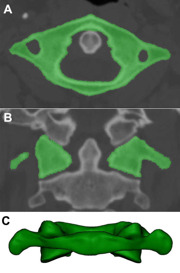
3D reconstruction of the atlas. a–b, The cortical bone and cancellous bone of the atlas were segmented and filled completely. c, 3D reconstruction of the atlas.
Figure 2.

3D anatomical morphology of the atlas; a, Axial view of the atlas. Point F represents the anterior tubercle of C1, and point P represents the posterior tubercle. b, Lateral view of the atlas. c–d, Points F and P overlap in the dorsal view of the atlas. e, The pedicle corridor is delineated from the dorsal view. f, Measurement of the long axis (LL, RL), short axis (LS, RS) and area of the pedicle corridor.
Figure 3.

Axial sketch of the atlas. a, The 3 green lines represent the inner, middle and lateral trajectories, respectively. The short yellow lines form a 2.75-mm-wide corridor to holding screws with a diameter of 3.5 mm and reserve 1 mm for the bone cortex. b, Points A, B and C represent the entry point of the inner, middle and lateral corridors, respectively. LA, LB, and LC represent the distances from points P to points A, B and C, respectively. c, The yellow curves form a 2.75-mm-wide corridor to hold screws with a diameter of 3.5 mm and reserve 1 mm for the bone cortex. α, β, γ represent the safe angles of the inner screw swing, middle screw swing and lateral screw swing, respectively.
Evaluation Criteria
The projection of the trajectory of all the volunteers was fitted into an ellipse. The long axis, short axis, area of the ellipse, screw length, and distance between the entry point and posterior tubercle were recorded. As described above, the screw lengths were represented by AA′, BB′, and CC′, the distances were represented by LA, LB, and LC, and the angle offsets of the screw were represented by α, β, and γ (Figure 3).
Statistic
All statistical analyses were performed using SPSS 19.0 (SPSS Inc., Chicago, IL, USA). Independent-samples T test was performed to analyze the long axis, short axis, and area of the screw corridor from the dorsal view of the atlas. One-way ANOVA and post hoc tests were performed to analyze the screw lengths of the inner, middle and lateral trajectorys, distances from point P to the entry points of A, B and C, and angle offsets of A, B and C from the axial view of the atlas. Descriptive statistics were performed for the width of the screw corridor from the horizontal view of the atlas.
Results
From the dorsal view of the atlas, the pedicle corridor was fitted into an ellipse, with an average long axis of 13.6 ± 2.4 mm, an average short axis of 5.2 ± 1.1 mm, and an average area of 57.5 ± 19.1 mm2. No significant difference was found in the long axis between the left and right atlas structures, short axis between the left and right atlas structures and area between the left and right atlas structures (Table 1). In men, the short axis of 93 pedicles was greater than 4 mm and that of 9 pedicles was less than 4 mm. In women, the short axis of 80 pedicles was greater than 4 mm and that of 18 pedicles was less than 4 mm. Thus, 27 cases (13.5%) had a short axis of less than 4 mm. From the axial view of the atlas, the safety pedicle corridor had an average width of 9.4 ± 1.8 mm. The average lengths from points A, B and C were 31.7 ± 3.1 mm, 28.7 ± 2.7 mm and 25.1 ± 3.0 mm, respectively, and no significant difference was found among the medial, middle and lateral trajectory (P < 0.05). The average distances between point P and entry points A, B and C were 17.1 ± 2.0 mm, 20.8 ± 2.2 mm and 24.5 ± 2.9 mm, respectively, and a significant difference was found among A, B and C (P < 0.05). With A as the entry point, the average outward angle was 16.1 ± 4.5°. With B as the entry point, the average swing angle was 25.5 ± 7.1°. With C as the entry point, the average swing angle was 16.1 ± 4.5°. A significant difference was found among A, B and C (P < 0.05) (Table 2).
Table 1.
Measurement of Atlas in Dorsal View.
| Ellipse | Long axis (mm) | Short axis (mm) | Area (mm2) |
|---|---|---|---|
| left+right, n = 200 | 13.58 ± 2.42 | 5.19 ± 1.09 | 56.26 ± 19.11 |
| Left, n = 100 | 13.48 ± 2.48 | 5.11 ± 1.13 | 55.02 ± 18.51 |
| Right, n = 100 | 13.68 ± 2.37 | 5.28 ± 1.04 | 57.5 ± 18.97 |
| P | 0.37 | 0.06 | 0.11 |
Table 2.
Measurement of Atlas in Horizontal View, N = 200.
| W (mm) | Screw length (mm) | Distance between entry point and point p (mm) | Safety angle offset (°) | |||||||
|---|---|---|---|---|---|---|---|---|---|---|
| AA′ | BB′ | CC′ | LA | LB | LC | α | β | γ | ||
| left+right | 9.41 ± 1.81 | 31.74 ± 3.07 | 28.69 ± 2.73 | 25.07 ± 2.97 | 17.07 ± 2.02 | 20.77 ± 2.21 | 24.52 ± 2.88 | 16.07 ± 4.51 | 25.45 ± 7.09 | 28.13 ± 5.75 |
| F | — | 439.21 | 775.53 | 251.34 | ||||||
| P | — | 0.000 | 0.000 | 0.000 | ||||||
| Post-hoc | — | medial-middle | medial-lateral | middle-lateral | medial-middle | medial-lateral | middle-lateral | medial-middle | medial-lateral | middle-lateral |
| P | — | 0.000 | 0.000 | 0.000 | 0.000 | 0.000 | 0.000 | 0.000 | 0.000 | 0.000 |
Discussion
Innovations of Atlas Screw Implantation
With the diversified development of atlas screw placement technology, an increased number of studies on the atlas were reported recently.10,12,13 Regarding the fixation and fusion of the upper cervical vertebrae, the short-segment posterior fixation technique is preferred. 14 Posterior bilateral transarticular screws are generally considered to be the best method for C1-C2 fusion. 15 However, this technique has some limitations and drawbacks, particularly the increased risk of injury to the vertebral artery. 16 However, atlas lateral mass screws have a serious problem because the large epidural venous plexus causes bleeding and nerve root injury in C2. Compared with lateral mass screws, pedicle screws have better pullout strength and biomedical stability. 17 Pan 16 proposed a modified method of screw placement to avoid bleeding in the venous sinus by placing the underside of the atlas posterior arch as the entry point and using a medial inclination of 10°. However, the medial inclination of the pedicle screw is difficult to control. In our study, pedicle corridor fixation perpendicular to the coronal plane was obtained rapidly by 3D reconstruction of the normal adult atlas. The area of the channel reflects the capacity of the channel to hold the number of screws. On the axial view of atlas, pedicle corridor fixation perpendicular to the coronal plane was delineated. A screw with a diameter of 3.5 mm was reserved, and the pedicle corridor on each side was divided into 3 parts by the sagittal plane-inner, middle and lateral trajectory. The lengths from points A, B and C were measured to reflect the stability of screw. The distances from points A, B and C to point P can provide a reference for the surgeon to find the entry point. When a 3.5-mm screw channel is reserved in the pedicle, the safe offset angle of the screw in the pedicle provides the surgeon with a tolerance of error.
Selection of Entry Points
In our study, the average length of the medial trajectory was 31.7 mm from point A, with an acceptable swing angle of 16°. The soft tissue anatomy was easily controlled with the spinous process as the center. The average length of lateral trajectory was the shortest from point C, which was 25.1 mm, with a safe medial angle of 28.1°. However, because of the obstruction of soft tissue, the angle of inclination from point C was difficult to control. The angle offset and length of the middle screw corridor were between the medial and lateral trajectory, but the location of point B was not easy to determine intraoperatively. During the operation, the medial edge of the atlas pedicle can be probed with a nerve probe, and 4 mm outside the edge can be used as the entry point. The safety pedicle corridor has an average width of 9.4 ± 1.8 mm, so the point is approximately 5 mm away from the lateral wall of the transverse foramen. Considering atlas anatomic variation, we recommend the preoperative measurement of the data to improve surgical safety. Additionally, the screws should be inserted along the lateral wall of the pedicle from point A. Ma, by anatomical analysis of 50 dry atlantoaxial vertebra samples, suggested that a short axis of the pedicle corridor of less than 4 mm was unsafe for pedicle screw placement. 5 In our study, we found that the average short axis of the screw corridor was 5.2 mm, and 8.8% of men and 18.4% of women had a short axis of less than 4 mm. Lee et al 18 reported that at least 5 mm of bone thickness is required to pass through a 3.5-mm pedicle screw safely without damaging any of the cortical margins. We believe that most of our volunteers can accommodate screws with a diameter of 3.5 mm, the entry point being the midpoint of the superior and inferior edges of the posterior arch. The remaining samples carry the risk of breaking the bone cortex in the atlas. Therefore, we recommend to select the position below the midpoint of the posterior arch for these patients to avoid damage to the vertebral artery and nerve root above the posterior arch. Otherwise, we recommend to remove approximately 4 mm of the posterior dorsalis cortex at the point of entry using rongeurs and curettes. 19
Axial Screw Direction Control
Hu’s study reported a greater medial inclination with a longer screw length and a greater width of the screw corridor. However, the medialization peaked at 20°. Therefore, pedicle screws with a medialization of 20° are recommended. 20 Ma drew a similar conclusion. 21 However, in practice, it is difficult to place the screw exactly at this angle because of soft tissue obstruction; even with the assistance of various navigation equipment, the phenomenon of screw placement error can occur.22,23 In our study, although a swing angle of 16° was obtained from point A, the orientation of the screw trajectory was recommended to be perpendicular to the coronal plane (with a medialization of 0°). Based on our experience, we suggest the following surgical tips to maintain the orientation. First, the lack of vertebral rotation should be confirmed. Second, a 2.5-mm-diameter drilling bit should be used to drill into the posterior arch to a depth of 20 to 25 mm. Third, no bleeding should occur after drilling. Fourth, no breakthrough should be observed in the screw trajectory. Finally, a 2.0-mm K-wire should be inserted, and then the angle between the K-wire and sagittal plane should be evaluated after bilateral tapping.
Advantages of screws perpendicular to the coronal plane
In our study, we analyzed the atlas of 100 volunteers. The pedicle corridor had an average width of 9.4 mm from the coronal plane, the long axis was 13.6 mm, and the short axis was 5.2 mm from the dorsal view of the atlas, which was sufficient to accommodate the 3.5-mm-diameter screws. Only 10 cases (19 pedicle corridor) had a short axis of less than 4 mm. However, to our knowledge, the previous literature does not include the measurement of atlas pedicle screws perpendicular to the coronal plane. We summarize the following advantages of screw placement perpendicular to the coronal plane. First, the entry point should be close to the midline, reducing the exposure of the atlas posterior arch during surgery and the risk of vertebral artery injury. In our study, only approximately 34 mm (distance between the entry point of the bilateral screws) of the posterior arch was required intraoperatively in most patients. Additionally, we can probe the lateral wall of the pedicle to determine the location of point A. Second, pedicle screws perpendicular to the coronal plane are more easily controlled and require less intraoperative fluoroscopy. The screw is placed along the lateral wall of the pedicle on the standard axial position of the atlas, and the puncture of lateral wall can be detected using a screw probe. During the operation, only lateral fluoroscopy is needed to acquire the sagittal direction of the screw. Third, the screws near the lateral wall of the pedicle (point A) should have an average length of 31.9 mm, which is significantly longer than that of the middle trajectory and lateral trajectory (points B and C). Finally, we consider that pedicle screw insertion from points A provides a swing angle of 16° although medialization of screw trajectory at point A is not allowed. Sometimes, because of the difficulty of soft tissue exposure, the entry point may be too close or beyond the medial wall of the pedicle. In this case, it is also safe to use a swing angle at point A, while the swing angles of point B and point C are smaller.
Limitation
Although the anatomical characteristics of the atlas pedicle were identified in our study through basic measurements of a large sample size, many deficiencies still need to be addressed. First, the pedicle corridor was fitted into an ellipse. Although conforming to most pedicle shapes, some pedicles still do not conform to an ellipse shape. Therefore, some errors may occur in the parameter measurement of the pedicle corridor. Second, the novel trajectory for atlas pedicle screws without medialization in the axial plane requires further clinical validation, even with extensive clinical application. Finally, because the cephalad angle to the transverse plane of screw can be easily obtained by intraoperative fluoroscopy, we did not measure the angle.
Conclusion
The measurement of 3D reconstruction based on CT provides the possibility of the placement of atlas screws without medialization. The projection of the trajectory is roughly elliptical. All the volunteers can accommodate a 3.5-mm pedicle screw perpendicular to the coronal plane if the posterior arch of the atlas can be managed correctly. Although there is a 16° safety outward angle, we recommend the orientation of the screw trajectory to be perpendicular to the coronal plane. Pedicle screws close to the pedicle lateral wall of atlas posterior arch perpendicular to the coronal plane is an advanced technique that is easy to master.
Abbreviations
- 3D
3-dimension
- Point P
the posterior tubercle of atlas
- Point F
the anterior tubercle of atlas
- LL
left long axis of projection for atlas pedicle screws
- RL
right long axis of projection for atlas pedicle screws
- LS
left short axis of projection for atlas pedicle screws
- RS
right short axis of projection for atlas pedicle screws
- W
width of screw corridor from axial view of atlas
- LA
distance from point A and point P
- LB
distance from point B and point P
- LC
distance from point C and point P
Footnotes
Declaration of Conflicting Interests: The author(s) declared no potential conflicts of interest with respect to the research, authorship, and/or publication of this article.
Funding: The author(s) disclosed receipt of the following financial support for the research, authorship, and/or publication of this article: This study was supported by Sichuan Key Science and Technology Plan Project (2016JY0108) and Zigong key science and technology project (2019YLSF05). Science and Technology Project of Sichuan Medical Association (2020SAT03).
ORCID iD: Chao Wu, MS https://orcid.org/0000-0002-7215-1460
References
- 1.Lu Y, Lee Y P, Bhatia NN, Lee TQ. Biomechanical comparison of C1 lateral mass—C2 short pedicle screw—C3 lateral mass screw-rod construct versus Goel-Harms fixation for atlantoaxial instability. Spine. 2018;44(7):e393–399. doi:10.1097/BRS.0000000000002868 [DOI] [PubMed] [Google Scholar]
- 2.Ma XY, Yin QS, Wu ZH, et al. C1 pedicle screws versus C1 lateral mass screws: comparisons of pullout strengths and biomechanical stabilities. Spine. 2009;34(4):371–377. doi:10.1097/BRS.0b013e318193a21b [DOI] [PubMed] [Google Scholar]
- 3.Squires J, Molinari RW. C1 lateral mass screw placement with intentional sacrifice of the C2 ganglion: functional outcomes and morbidity in elderly patients. Eur Spine J. 2010;19(8):1318–1324. doi:10.1007/s00586-010-1452-4 14 [DOI] [PMC free article] [PubMed] [Google Scholar]
- 4.Hu Y, Kepler CK, Albert TJ, et al. Accuracy and complications associated with the freehand C1 lateral mass screw fixation technique: a radiographic and clinical assessment. J Neurosurg Spine. 2013;18(4):372–377. doi:10.3171/2013.1.SPINE12724 [DOI] [PubMed] [Google Scholar]
- 5.Ma XY, Yin QS, Wu ZH, Xia H, Liu JF, Zhong SZ. Anatomic considerations for the pedicle screw placement in the first cervical vertebra. Spine. 2005;30(13):1519–1523. doi:10.1097/01.brs.0000168546.17788.49 [DOI] [PubMed] [Google Scholar]
- 6.Ma J, Tang J, Wang DG, Zhu Y, Sui T, Cao X. Comparison of perpendicular to the coronal plane versus inner inclination for atlas pedicle screw insertion: an anatomic and radiological study in human cadavers. Int Orthop. 2016;40(1):141–147. doi:10.1007/s00264-015-2947-8 [DOI] [PubMed] [Google Scholar]
- 7.Hu Y, Dong WX, Spiker WR, et al. An anatomic study to determine the optimal entry point, medial angles, and effective length for safe fixation using posterior C1 lateral mass screws. Spine. 2015;40(4):e191–198. doi:10.1097/BRS.0000000000000715 [DOI] [PubMed] [Google Scholar]
- 8.Dawes B, Perchyonok Y, Gonzalvo A. Radiological evaluation of C1 pedicle screw anatomic feasibility. J Clin Neurosci. 2018;51:18–21. doi:10.1007/s00264-015-2947-8 [DOI] [PubMed] [Google Scholar]
- 9.Kim HB, Lee MK, Lee YS, Sohn J-Y, Jung SK, Park JH. An assessment of the inner angle of inserted subaxial cervical pedicle screw during surgery: practical use of preoperative CT scanning and intraoperative X-rays. Neurol Med Chir. 2016;51(4):18–21. doi:10.1016/j.jocn.2018.01.006 [DOI] [PMC free article] [PubMed] [Google Scholar]
- 10.Tan MS, Wang HM, Wang YT. Morphometric evaluation of screw fixation in atlas via posterior arch and lateral mass. Spine. 2003;28(9):888–895. doi:10.1097/01.BRS.0000058719.48596.CC [DOI] [PubMed] [Google Scholar]
- 11.Lee M, Cassinelli E, Riew KD. The feasibility of inserting atlas lateral mass screws via the posterior arch. Spine. 2006;31(24):2798–2801. doi:10.1097/01.brs.0000245902.93084.12 [DOI] [PubMed] [Google Scholar]
- 12.Christensen DM, Eastlack RK, Lynch JJ, Yaszemski MJ, Currier BL. C1 anatomy and dimensions relative to lateral mass screw placement. Spine. 2007;32(8):844–848. doi:10.1097/01.brs.0000259833.02179.c0 [DOI] [PubMed] [Google Scholar]
- 13.Wang HW, Yin YH, Jin YZ, et al. Morphometric measurements of the C1 lateral mass with congenital occipitalization of the atlas. World Neurosurg. 2019;121:e1–7. doi:10.1016/j.wneu.2018.08.016 [DOI] [PubMed] [Google Scholar]
- 14.Goel A, Desai KI, Muzumdar DP. Atlantoaxial fixation using plate and screw method: a report of 160 treated patients. Neurosurgery. 2002;51(6):1351–1357. [PubMed] [Google Scholar]
- 15.Fountas KN, Kapsalaki EZ, Karampelas I, et al. C1–C2 transarticular screw fixation for atlantoaxial instability. South Med J. 2004;97(11):1042–1048. doi:10.1097/01.SMJ.0000144610.35591.69 [DOI] [PubMed] [Google Scholar]
- 16.Pan J, Li L, Qian L, Tan J, Sun G, Li X. C1 lateral mass screw insertion with protection of C1-C2 venous sinus. Spine. 2010;35(21):E1133–E1136. doi:10.1097/BRS.0b013e3181e215ff [DOI] [PubMed] [Google Scholar]
- 17.Xiang-Yang MA, Qing-Shui Y, Zeng-Hui WU, et al. C1 pedicle screws versus C1 lateral mass screws: comparisons of pullout strengths and biomechanical stabilities. Spine. 2009;34(4):371–377. doi:10.1097/BRS.0b013e318193a21b [DOI] [PubMed] [Google Scholar]
- 18.Lee M, Cassinelli E, Riew KD. The feasibility of inserting atlas lateral mass screws via the posterior arch. Spine. 2006;31(5-supp-S):69S–69S. doi:10.1016/j.spinee.2006.06.174 [DOI] [PubMed] [Google Scholar]
- 19.Tan MS, Dong L, Wang WJ, et al. Clinical application of the “pedicle exposure technique” for atlantoaxial instability patients with a narrow C1 posterior arch. J Spinal Disord Tech. 2015;28(1):25–30. doi:10.1097/BSD.0000000000000078 [DOI] [PubMed] [Google Scholar]
- 20.Yong H, Dong W-X, Spiker WR, et al. An anatomic study to determine the optimal entry point, inner angles, and effective length for safe fixation using posterior C1 lateral mass screws. Spine. 2015;40(4):e191–198. doi:10.1097/BRS.0000000000000715 [DOI] [PubMed] [Google Scholar]
- 21.Jun M, Tang J, Wang D, Zhu Y, Sui T, Cao X. Comparison of perpendicular to the coronal plane versus inner inclination for atlas pedicle screw insertion: an anatomic and radiological study in human cadavers. Int Orthop. 2016;40(1):141–147. doi:10.1007/s00264-015-2947-8 [DOI] [PubMed] [Google Scholar]
- 22.Sugawara T, Higashiyama N, Kaneyama S, Sumi M. Accurate and simple screw insertion procedure with patient-specific screw guide templates for posterior C1-C2 fixation. Spine. 2016;42(6):e340–346. doi:10.1097/BRS.0000000000001807 [DOI] [PubMed] [Google Scholar]
- 23.Kosmopoulos V, Schizas C. Pedicle screw placement accuracy. Spine. 2007;32(3):E111–E120. doi:10.1097/01.brs.0000254048.79024.8b [DOI] [PubMed] [Google Scholar]