Abstract
Objective.
This article presents a novel transcranial magnetic stimulation (TMS) pulse generator with a wide range of pulse shape, amplitude, and width.
Approach.
Based on a modular multilevel TMS (MM-TMS) topology we had proposed previously, we realized the first such device operating at full TMS energy levels. It consists of ten cascaded H-bridge modules, each implemented with insulated-gate bipolar transistors, enabling both novel high-amplitude ultrabrief pulses as well as pulses with conventional amplitude and duration. The MM-TMS device can output pulses including up to 21 voltage levels with a step size of up to 1100 V, allowing relatively flexible generation of various pulse waveforms and sequences. The circuit further allows charging the energy storage capacitor on each of the ten cascaded modules with a conventional TMS power supply.
Main results.
The MM-TMS device can output peak coil voltages and currents of 11 kV and 10 kA, respectively, enabling suprathreshold ultrabrief pulses (> 8.25 μs active electric field phase). Further, the MM-TMS device can generate a wide range of near-rectangular monophasic and biphasic pulses, as well as more complex staircase-approximated sinusoidal, polyphasic, and amplitude-modulated pulses. At matched estimated stimulation strength, briefer pulses emit less sound, which could enable quieter TMS. Finally, the MM-TMS device can instantaneously increase or decrease the amplitude from one pulse to the next in discrete steps by adding or removing modules in series, which enables rapid pulse sequences and paired-pulse protocols with variable pulse shapes and amplitudes.
Significance.
The MM-TMS device allows unprecedented control of the pulse characteristics which could enable novel protocols and quieter pulses.
Keywords: Transcranial magnetic stimulation, modular multilevel converter, cascaded H-bridge, pulse shape, sound, loudness
1. Introduction
Transcranial magnetic stimulation (TMS) devices comprise an electromagnet coil placed on the subject’s head and a pulse generator that supplies high current pulses to the coil. The coil emits intense, brief magnetic pulses, that, in turn, induce an electric field in the brain, non-invasively stimulating cortical neurons. TMS is widely used as a tool for probing and modulating brain function in research and clinical applications [1].
Existing TMS devices, however, have several significant limitations. First, TMS pulse delivery is associated with a loud clicking sound that can be as high as 140 dB resulting from electromagnetic forces in the coil [2]. The loud noise presents a risk to the hearing of the TMS subject and the operator that necessitates the use of hearing protection [2–4]. Further, by evoking an auditory response synchronized with the electromagnetic stimulus, the sound compromises the spatial localization of the stimulation effects, impacts neuromodulation, and complicates blinding, significantly impeding both basic research and clinical applications of TMS. A contributing factor to the coil sound is the typical biphasic pulse duration of 150‒400 µs, which corresponds to a vibration spectral peak at 5–13 kHz due to the coil winding electromagnetic forces [2, 5]. Second, existing TMS devices have limited adjustability of their pulse characteristics [6, 7]. Standard TMS devices generate sinusoidal pulses with a fixed shape and duration. More advanced devices allow some adjustment of the pulse duration and shape [8–12]. Such devices have enabled important findings regarding the effect of pulse shape and duration on neural activation thresholds [13], differential neural recruitment in the brain [14–19], lasting neuromodulatory effects [20, 21], as well as the sensation of scalp stimulation [22]. However, these devices still have a restricted range of the shape (e.g., only sinusoidal or only rectangular), duration (e.g., lacking very brief and very long pulses), and amplitude (e.g., insufficient amplitude for suprathreshold brief or complex pulses) [5, 7, 23]. Third, TMS devices have significant limitations in their ability to deliver rapid sequences of pulses for applications such as paired-pulse, triple-pulse, or quadripulse paradigms, requiring the combination of a corresponding number of individual TMS devices, and, moreover, the shape of such pulses is typically restricted to monophasic sinusoidal [24–26].
Addressing this need, we present MM-TMS, the first TMS device to use a modular multilevel circuit topology at full TMS energy levels, allowing unprecedented control of the pulse shape, width, and amplitude. This development builds upon our prior work, including demonstration of flexible pulse synthesis with a modular multilevel topology at lower energy levels [27, 28].
The MM-TMS device consists of ten cascaded H-bridge modules, whose output voltages add up to form the stimulation coil voltage. This summation of the module voltages allows the generation of a significantly higher voltage (< 11 kV) than conventional TMS devices (< 2.8 kV). The available high voltages enable the generation of ultrabrief stimulation pulses (e.g., 33 µs biphasic) whose dominant vibration frequency is shifted to frequencies above the upper limit of human hearing, expected to make TMS quieter [5, 23]. Conversely, firing the modules sequentially produces very long pulses (> 400 µs), matching or exceeding the duration of conventional TMS pulses, enabling, for example, the measurement of extended strength–duration curves [13, 29].
Further, the modular topology provides 21 voltage levels within a pulse, allowing the generation of complex waveforms such as polyphasic (multicycle) pulses that can reduce the neural activation threshold and produce more robust motor evoked responses [30, 31]. The polyphasic pulses can also be amplitude-modulated, for example, with a Gaussian envelope, which has a narrower frequency bandwidth and was suggested to reduce the acoustic spectral sidebands and therefore the audible acoustic noise if the dominant frequency is concurrently shifted above the upper hearing limit [23]. Continuous kilohertz waveforms may have important neuromodulatory effects as well [32–36]. Generally, the control of the pulse characteristics over a wide range of durations and shapes may enable more selective neural recruitment and stronger neuromodulation [20, 21].
Finally, the MM-TMS device can generate rapid sequences of pulses. For example, various paired-pulse or triple-pulse paradigms [24, 25] can be implemented by instantaneously increasing or decreasing the output amplitude from one pulse to the next with the addition or subtraction of modules connected in series. Similarly, quadripulse bursts [26, 37] can be implemented by firing groups of modules in a sequence. In these pulse sequences, the parameters of the individual pulses can be controlled independently of the other pulses, although the sequential firing of module groups limits the number of voltage levels within each pulse and hence the flexibility of pulse shaping.
This paper presents the design, implementation, and electrical and acoustic characterization of an MM-TMS prototype. The measurements demonstrate the ability of the MM-TMS device to control the pulse characteristics over a wide range of shapes, widths, and amplitudes and to leverage this control for the reduction of the acoustic emissions of the coil.
2. Device design
2.1. Circuit topology
Figure 1 shows the MM-TMS circuit topology. Arm A and arm B, each consisting of five cascaded modules in our implementation, differentially drive the stimulation coil L. The coil voltage, VL, is the difference of the two arm voltages, VAO and VBO. The voltage of each arm amounts to the sum of its five modules’ output voltages, where Vi denotes the output voltage of module i. Thus, the instant coil voltage is the sum of all module voltages,
| (1) |
Figure 1.
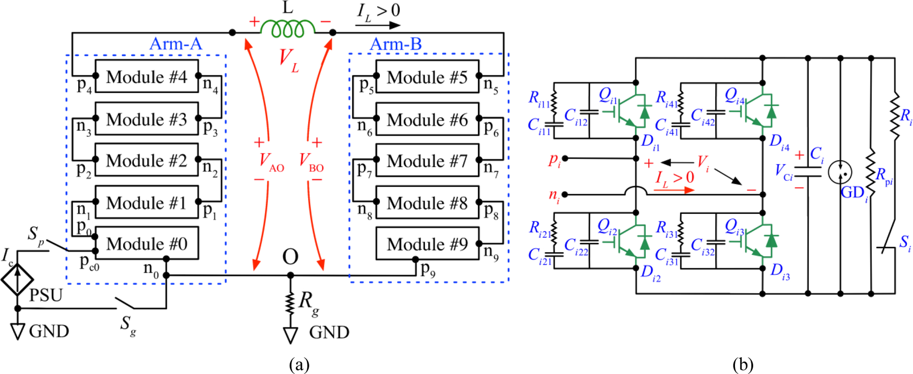
(a) Schematic diagram of the MM-TMS pulse generator, where Arm-A and Arm-B drive the two terminals of the stimulation coil L, respectively, and each arm consists of five cascaded modules. The common point O of the two arms is grounded via a resistor Rg. In each arm, terminal pi of module #i is connected to terminal ni+1 of module #(i+1), where i = 0, 1, 2, …, 9 denotes the individual module. (b) Each module employs a full-bridge circuit interfacing an energy storage capacitor Ci. Switches Qi1/Di1, Qi2/Di2, Qi3/Di3, and Qi4/Di4 are IGBT modules with freewheeling diodes. Capacitors Ci12–Ci42 and Ci11–Ci41,, and resistors Ri11–Ri41 form snubbers. The energy storage capacitor Ci is discharged by a discharge resistor Ri when relay Si is closed. In case of the relay’s failure, a secondary discharge resistor Rpi is directly connected to the capacitor Ci, discharging the capacitor to a safe voltage below 15 V in 5 minutes. GDi denotes an array of parallel gas discharge tubes (GDTs). The power supply unit (PSU) charges the module capacitors with current Ic. The PSU’s positive terminal is connected to the positive terminal pc0 of C0, the storage capacitor of module #0, and its negative output is connected to bridge output n0 of module #0. Relay Sp disconnects the PSU from the power stage when the coil pulse is generated. Relay Sg is on during charging and is typically off during the pulse, but can also be on if it is preferable to reference the coil voltages to ground.
Compared to existing TMS devices, in which one terminal of the stimulation coil is grounded, the differential MM-TMS coil drive halves the system peak voltage relative to the ground and thus reduces high-voltage insulation requirements and enhances safety. For example, arm voltages of ±5.5 kV to ground can generate coil voltage of ±11 kV.
As shown in figure 1(b), each module employs an H-bridge circuit [38], implemented with high-voltage, high-current insulated-gate bipolar transistor (IGBT) switches and appropriate snubber and gate drive circuits, following our approach for prior, simpler TMS device designs [8–10, 31]. The module’s output voltage, Vi, depends on the switches’ states and is equal to VCi, 0, or −VCi, where VCi denotes the energy storage capacitor of module i. Typically, before a pulse is initiated at time t = t0, each module is charged to the same reference voltage, VCi (t = t0) = VCref, which is set by the controller. Inserting all available combinations of switch states into equation (1) yields 21 different coil voltage levels, VL = {0, ±1, ±2, …, ±10} × VCref. Hence, there are two ways of controlling the output voltage level. The first approach is to adjust VCref, which provides a continuous voltage range, but is relatively slow since it requires charging or discharging the capacitors. The second approach is to adjust the number of modules connected in series, which provides discretized control of the output but is very fast, as it is limited only by the switching speed of the transistors (~ 1 µs), thus allowing unprecedented instantaneous control over the pulse shape.
Table 1 shows the definitions of the module states with the corresponding transistor states and module output voltages. States 1–4 actively define the output voltage, which is determined by the commanded transistor states, regardless of the load condition. These states are typically used during all pulse phases except for the last one, allowing the pulse waveform to be accurately controlled [9–11]. For states 0 and 5–8, the module output voltage depends on the diode states, which in turn depend on the circuit voltages and currents applied to the diodes. These states are used in the last phase of the pulse to automatically terminate the pulse when the coil current decays to zero as well as during the short switching transitions between phases [10].
Table 1.
Module states and corresponding switch states and module output voltage
| Module state | Transistor switch state | Module output | |||
|---|---|---|---|---|---|
| Q i1 | Q i2 | Q i3 | Q i4 | V i | |
| 0 | Off | Off | Off | Off | {−VCi, 0, VCi} |
| 1 | On | Off | On | Off | V Ci, |
| 2 | Off | On | Off | On | −VCi |
| 3 | On | Off | Off | On | 0 (bypass) |
| 4 | Off | On | On | Off | 0 (bypass) |
| 5 | Off | On | Off | Off | {−VCi, 0} |
| 6 | Off | Off | On | Off | {0, VCi} |
| 7 | On | Off | Off | Off | {0, VCi} |
| 8 | Off | Off | Off | On | {−VCi, 0} |
2.2. Energy storage capacitor charging scheme
There are several options for charging the module capacitors. One approach is to embed a charger into each module. Embedded chargers, however, require ten galvanically-isolated chargers and a very high isolation voltage of ±5 max (VCref) (±5.5 kV in our implementation) for the power and control signal connections to the charger. Alternatively, each of the coil terminals could be connected to a conventional grounded charger, and the modules would be charged one at a time by putting the remaining arm modules in bypass mode [27]. This approach requires the charger output to withstand the high voltage of ±5 max (VCref) applied to the coil terminals during pulsing, or, alternatively, it requires a high voltage switch to be interposed between the charger and the coil terminals.
To circumvent the need for high-voltage isolation or switches in these approaches, we implemented a capacitor-charging scheme that requires switches with only > max(VCref) voltage rating. As shown in figure 1(a), the charger’s positive output is connected to the energy storage capacitor’s positive terminal pc0 in module #0, and the grounded charger’s negative output is connected to output n0 of module #0. Figure 2 illustrates the ten modules’ state arrangements for capacitor charging. For module #0 charging t ∈ (t1, t2], it is in state 1 and the other modules are in state 0. When the charger is activated (ctr is logic low), the charging current Ic goes through energy storage capacitor C0 and diode D03 of module #0. For charging of module #1 during t ∈ (t3, t4], Q01 of module #0 is turned on (state 7), and modules #2 – #9 are in the bypass mode (state 3, see Table 1), parallelizing the charger and the energy storage capacitor C1 of module #1. When the charger is activated, the charging current Ic goes through the energy storage capacitor C1 of module #1 and D11 and D13.
Figure 2.
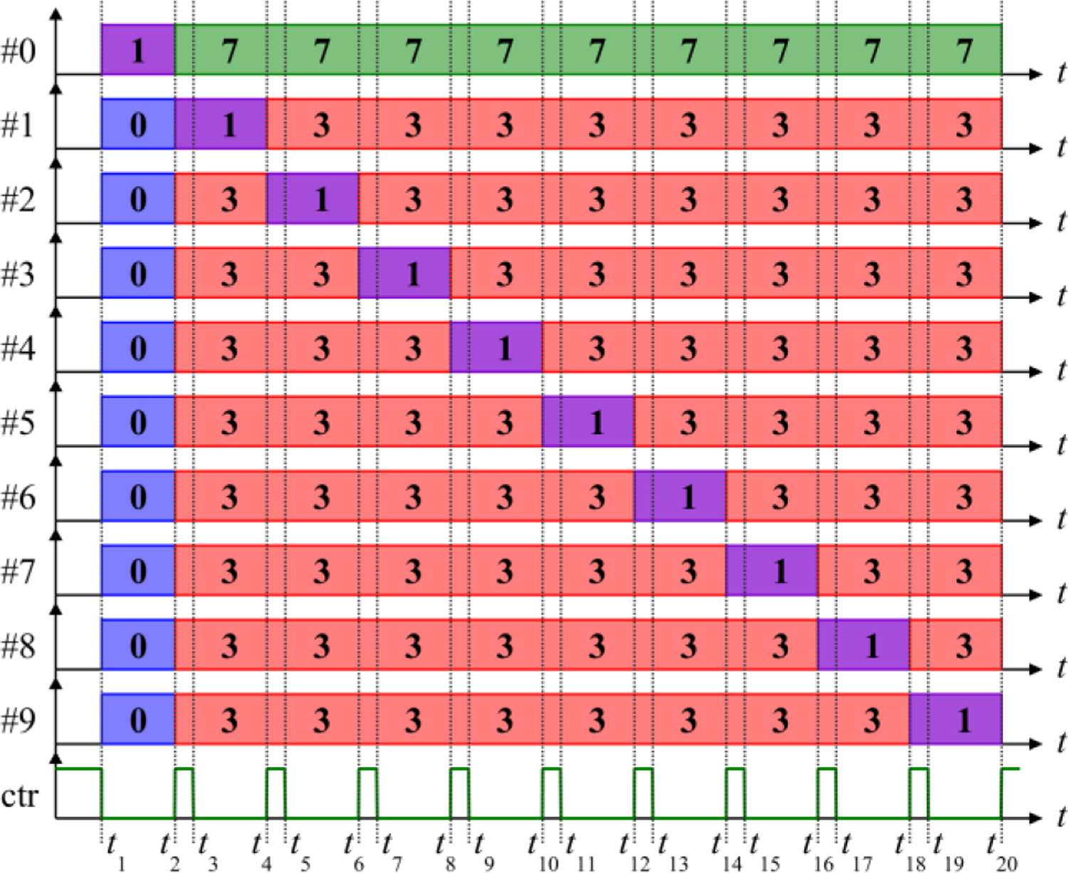
Sequence of modules states used for capacitor charging. The module capacitors are charged one at a time by the PSU. When control signal ‘ctr’ is clear, the PSU is activated, charging the module in state 1; when ctr is set to logic high, the charging stops.
When charging modules #1 – #9, the charging current flows through the coil, but that current is very small (< 4 A). There is also a transient current between the snubber capacitors connected to node n0 in module #0 and the energy storage capacitor of the module being charged, which also flows through the coil. These current spikes reach 206 µs in duration but are only < 350 A in amplitude (less than 4% of the MM-TMS peak current), and therefore do not induce a significant electric field pulse (supplementary figure S12). Moreover, since the amplitude of these spikes depends on the difference between the voltages on the module #0 snubbers and the capacitor on the module being charged, the spike amplitude can be reduced to arbitrarily small values by charging the modules in several rounds by small voltage increments.
2.3. Pulse shape control
2.3.1. Near-rectangular electric field pulses.
Figure 3 illustrates four example control sequences for biphasic magnetic pulses with a nearly rectangular electric field waveform and a broad pulse width range. In figure 3(a), the ten modules’ states are synchronized. During the first pulse phase, t ∈ (t0, t1], each module operates in state 1, ramping up the stimulation coil with a positive voltage of . At the beginning of the second phase at t = t1, all modules switch to state 2, ramping down the coil current with a negative voltage of . In the third phase, starting at t = t3, all modules switch back to state 1, followed by a snubbing sequence (see next section). These pulses are analogous to the biphasic pulses generated by TMS devices practically comprising a single module [9–11], but afford significantly higher output voltages, enabling briefer suprathreshold stimulation pulses.
Figure 3.
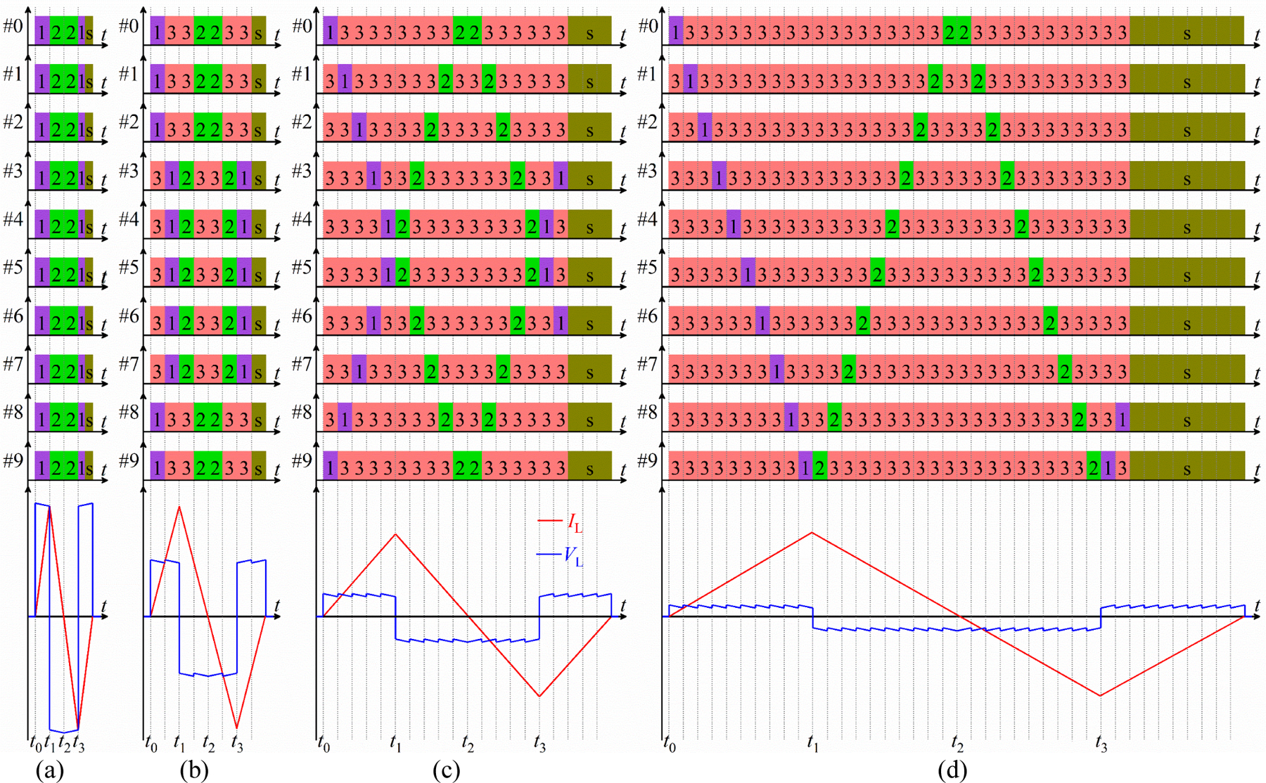
Module switching sequences for positive biphasic pulses with a wide range of pulse widths. Y-axes indicate module number, x-axes mark time intervals of the states, and colored numbers indicate switch states. State “s” denotes state sequences for active subbing, which does not affect the circuit behavior until the coil current decays to zero at the end of the TMS pulse, when the snubbing starts to dampen the coil ringing (see Supplementary Material). (a) For the briefest pulses, the ten modules’ switch states are synchronized. (b) Two module groups consisting of five modules in series connection sequentially drive the coil (5+5 scheme). (c) Five module groups consisting of two modules in series connection sequentially drive the coil (2+2+2+2+2 scheme). (d) Each of the ten modules sequentially drives the coil (1+1+1+1+1+1+1+1+1+1 scheme). Experimental implementations of these pulses are shown in figure 6.
However, the synchronized scheme in figure 3(a) can only be used for relatively brief pulses because of the small total series capacitance of Ci/10 driving the coil. To generate longer pulses, the control schemes in figures 3(b)–(d) fire groups of modules sequentially. Sequential firing reduces the available peak coil voltage, but this is acceptable since longer electric field pulses require lower amplitudes for suprathreshold stimulation.
In figure 3(b), the ten modules are divided into two groups, each of which consists of five modules, and in each module group, the modules’ states are synchronized. For example, modules #0, #1, #2, #8, and #9 form a module group, and the remaining modules (#3 – #7) form the other group. We refer to this scheme as ‘5+5’. During the pulse, one module group is activated at a time, while the other is in a bypass state, imposing ±5VCref on the stimulation coil. For example, when t ∈ (0, t1], the two module groups sequentially charge the stimulation coil with a voltage of +5VCref.
In figure 3(c), two modules, both of which have the same state, form a group. In this ‘2+2+2+2+2’ scheme, the five groups are formed by modules {#0, #9}, {#1, #8}, {#2, #7}, {#3, #6}, and {#4, #5}, respectively. At any instant during the pulse, one module group charges or discharges the coil with the remaining four module groups in the bypass state, leading to a coil voltage of ±2VCref. For example, during t ∈ (0, t1], the five module groups sequentially charge the stimulation coil with a voltage of +2VCref.
In figure 3(d), each module sequentially charges or discharges the stimulation coil with the remaining nine modules in the bypass state, imposing ±VCref on the stimulation coil. In this ‘1+1+1+1+1+1+1+1+1+1’ scheme, the ten modules sequentially charge the stimulation coil with a voltage of +VCref during t ∈ (0, t1].
The control schemes have important symmetries. First, at each time during a pulse, the device uses an equal or approximately equal number of modules from the two power stage arms (A and B). The symmetric involvement of both arms ensures that the coil common-mode voltage is close to zero [27, 39]. Second, the module groups’ state timings are symmetric with respect to the phase transition points to avoid severe unbalance of the capacitor voltages due to different discharging and charging currents. For example, during t ∈ (0, t2], the modules’ state timing is symmetric with respect to t = t1, ensuring approximately the same discharging and charging current for each module during a pulse. Since the discharging and charging of the capacitors is largely symmetric, most of the pulse energy is returned to the capacitors at the end of the pulse, and this energy can be recycled from pulse to pulse, as in other efficient repetitive TMS devices [6, 9–11, 40]. Note that schemes with +3VCref and +4VCref are also possible in ‘3+3+3’ and ‘4+4’ schemes by setting the unused 1 or 2 modules, respectively, to bypass mode for the duration of the whole pulse.
Using the same approach, we can also develop module state timings for monophasic magnetic pulses with a wide range of pulse widths (a monophasic pulse is essentially half of a biphasic pulse). Electric field pulses with asymmetric phase amplitude and duration [9, 10] can be generated by combining brief, high-amplitude phases of synchronous firing of the modules with long, low-amplitude phases of sequential firing of the modules. Inversion of the pulse voltage polarity is trivially achieved in MM-TMS by flipping the polarity of the output voltage of each module.
Finally, schemes using sequential firing of the modules should consider limitations on the maximum current that the IGBTs can withstand during the hard (forced) commutation when a module switches from diode conduction to IGBT conduction of the current [41]. This consideration also applies for modulation schemes, such as pulse width modulation, that switch each module frequently to approximate accurately a reference pulse waveform [12, 27, 28, 38, 39].
2.3.2. Complex pulse waveforms.
The multilevel topology of MM-TMS enables the generation of complex pulse waveforms. For example, the device can approximate a sinusoidal polyphasic coil voltage VL and resultant coil current IL with a Gaussian amplitude envelope by staircase discretization of the waveform. Due to the device’s rich redundancies of module states, various modulation schemes can produce such a waveform. Considering the trade-off between the practicality and approximation accuracy, we designed a modulation scheme consisting of 61 modulation states, where each state has the same duration. As illustrated by figure 4, two modules construct a module group, and the module states are synchronized within each of the five module groups. The modulation scheme approximates a sinusoidal polyphasic coil voltage with a Gaussian amplitude envelope by connecting different module groups in series. Using redundant module states, the modulation scheme balances the module voltages by discharging and charging the same capacitor with approximately the same coil current and duration.
Figure 4.
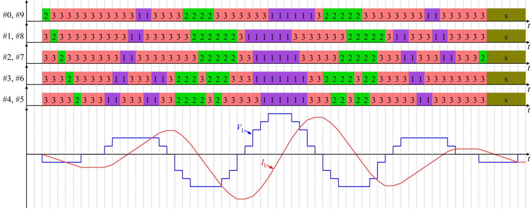
Module state sequence (top) to generate a polyphasic sinusoidal pulse with a Gaussian amplitude envelope (bottom). State diagram conventions are as in figure 3. For simplicity the illustration is for constant module capacitor voltages.
2.4. Pulse snubbing
For the pulse application featuring large currents, the snubbers are essential to limit the potentially damaging voltages and currents in semiconductors during switching. Figure 1(b) shows the snubbers included in each module of the proposed topology. During IGBT turn-off, the capacitors Ci12, Ci22, Ci32, and Ci42 primarily serve to take over a portion of the IGBT current, while Ci11–Ri11, Ci21–Ri21, Ci31–Ri31, and Ci41–Ri41 mainly dampen the voltage ringing across the collector and emitter during turn-off transients [9, 10]. The IGBT’s minimum snubbing requirement determines the capacitance of Ci12, Ci22, Ci32, and Ci42 since a larger capacitance increases the switching loss and stresses the IGBT during turn-on.
The snubber capacitors, however, cause ringing at the end of each pulse [9], [10]. Therefore, we deployed active snubbing, which uses the module IGBTs to dissipate the snubber capacitor energy at the end of a pulse. We extended our prior active snubbing approach [10] by leveraging the multi-module topology of MM-TMS to interleave the snubbing switching across the modules, which enabled smoother damping waveforms and reduced switching frequency of the individual IGBTs compared to snubbing with synchronized module switching. Details of the active snubbing switching sequences and performance are presented in the Supplementary Material.
In the MM-TMS device, we use low-inductance bus bar connections between the energy-storage capacitor Ci and switches Qi1/Di1 – Qi2/Di2 and Qi3/Di3 – Qi4/Di4. This obviates the need for snubbers across the IGBT half-bridges, which were necessary in other IGBT-based TMS devices [10].
2.5. Circuit implementation
We constructed a ten-module MM-TMS device based on the circuit in figure 1, with maximum coil voltage of 11 kV and maximum coil current of 10 kA, which we had estimated to be necessary for suprathreshold cortical stimulation with ultrabrief pulses (33 µs biphasic) [23]. Table 2 summarizes the parameters of the key components of the device. The device was assembled in a 35U Sound Control Cabinet (Rackmount Solutions, TX, USA) cabinet, which suppresses the emission of pulsed sound by the power components and interconnections.
Table 2.
Key MM-TMS circuit implementation components.
| Components | Function | Key parameters | Part number | Manufacturer |
|---|---|---|---|---|
| Qi1/Di1, Qi2/Di2, Qi3/Di3, Qi4/Di4 | Coil Switch | IGBT: 1700 V / 1800 A | FF1800R17IP5P | Infineon |
| C i | Energy storage | 225 μF, polypropylene film | 700D227912–409 | SB Electronics |
| Qi1, Qi2, Qi3, Qi4 gate driver | Gate driver |
VGE = −8 V (off), 22 V(on) RG = 1 Ω |
HV4–40I | Floeth Electronic |
| L | Stimulation coil | 11.7 μH | DCC* | Custom |
| Ci12, Ci22, Ci32, Ci42 | Snubber | 1600 V / 0.47 µF, polypropylene film | FKP4T034707H00KYSD | WIMA |
| Ci11, Ci21, Ci31 Ci41 | Snubber | 1600 V / 0.94 µF, polypropylene film | (2) FKP4T034707H00KYSD | WIMA |
| Ri11, Ri21, Ri31, Ri41 | Snubber | 0.125 Ω, wire wound | (4) RS010R5000FE73 | Vishay Dale |
| R i | Primary dumping resistor | 7.5 kΩ / 600 W | (6) PF2472–5KF1 | Riedon |
| R pi | Permanent dumping resistor | 300 kΩ / 27W | (6) RR03J300KTB | TE Connectivity |
| R g | Grounding resistor | 1 MΩ / 7W | (1) 104BA105KDS | Ohmite |
| S g , S p | Charging Relay | 3.5 kVAC / 3A | (1) 5503–24-1 | Coto Technology |
| S i | Discharging Relay | 7 kVAC / 2 A | (1) DBT72410U | Cynergy3 |
| GDi | Gas discharge tube | 1.6 kV / 5 kA | (12) 2095–160-BT1LF | Bourns |
| PSU | Capacitor charger | Output: 1.5 kV, 2 × 2 A | (2) Tesla Rapid PSU | Magstim |
|
| ||||
| Control | Digital controller | User-reconfigurable FPGA, 96 3.3 V digital I/O lines | sbRIO-9607 | National Instruments |
2.5.1. Energy storage capacitors and charging.
For the proposed 11 kV/10 kA pulse generation, the voltage rating of the energy storage capacitor Ci in each module must be larger than 1.1 kV, and its peak-current rating must be larger than 10 kA. Given the inductance (11.7 µH) of the quiet stimulation coil designed for the MM-TMS device [42] (see section 2.5.5), the total capacitance seen by the coil should range from 20 µF to 35 µF to achieve not only the required minimal biphasic pulse duration of 33 µs, but also a range of longer pulse widths and efficient near-rectangular electric field pulse shapes [8, 10, 43]. Since the modules are connected in series, the energy storage capacitance of each module should therefore be 200 µF to 350 µF. In addition, to handle fast switching of large current, it is essential to implement a capacitor with a low equivalent series inductance to suppress the voltage spike during the IGBT’s turn-off. Furthermore, the low equivalent series resistance is critical to limit losses and temperature rise with the large current. Based on these considerations, we selected a power ring film capacitor for Ci with low stray inductance (< 5 nH) and resistance (< 250 µΩ), high voltage rating (1.2 kV dc), and extreme current for small duty ratios (> 7.5 kA). The module output is protected from a significant overvoltage by gas discharge tubes in parallel with the capacitor.
Using the charging scheme described in section 2.2, the ten modules’ energy storage capacitors are charged sequentially by two parallel Magstim power supply units (PSUs) controlled by a custom electronics interface. The capacitor voltage is sensed by a voltage divider and fed to one input of a comparator. The comparator’s other input is fed from a digital-to-analog converter programmed with the controller’s scaled target voltage, VCref. When the target voltage is reached, the comparator’s output is set to logic high, and the charging stops.
2.5.2. IGBT switches and gate drivers.
Switches Qi1/Di1 ‒ Qi2/Di2 and Qi3/Di3 ‒ Qi4/Di4 in each module are implemented with a half-bridge IGBT module rated at 1.7 kV and 1.8 kA (FF1800R17IP5P). The half-bridge module integrates the upper and lower IGBT (for example, Qi1 and Qi2) and their freewheeling diodes (Di1 and Di2, respectively), minimizing the parasitic inductance and suppressing the turn-off voltage spike. Given the maximum output peak voltage of 11 kV, each module has a maximum working voltage of 1.1 kV; with rating voltage of 1.7 kV, FF1800R17IP5P has therefore a 600 V safety margin to accommodate the voltage spikes introduced by stray inductance during switching transients.
FF1800R17IP5P has a dc current rating of 1.8 kA and a repetitive peak current rating of 3.6 kA for 1 ms pulses. While this is below the MM-TMS device’s maximum pulse current of 10 kA, below a junction temperature of 125 oC, IGBTs can withstand a brief current that is about ten times larger than its rating current [44–46]. The junction temperature depends on the switching loss that consists of the conducting losses and switching losses. As discussed in section 2.4, snubbers are added to partly take over the current during switching, reducing the switching loss. Further, it is necessary to reduce the conducting loss by decreasing the IGBTs’ on-state voltage and preventing desaturation at high currents. Therefore, we shifted the voltage range of a commercial gate driver to produce a gate–emitter voltage of 22 V in the on-state, which is higher than the standard value of 15 V. The selected gate voltage is an improved trade-off between the IGBTs’ on-state voltage and gate–emitter voltage limit. Besides, the gate driver’s output resistance is set to the minimum value (RG = 1 Ω) determined by the gate driver’s maximum output current, ensuring a switching time of about 1 µs.
2.5.3. Connections within and between modules.
For the proposed MM-TMS device featuring fast switching with a large current, it is essential to minimize any stray inductance to optimize the performance, including the stray inductance of the connection between IGBTs and the energy storage capacitor on each module as well as the interconnections between modules. Minimized parasitic inductance of the connection between the IGBTs and the energy storage capacitor suppresses the IGBT voltage spike during switching, whereas minimized parasitic inductance of the connection between the modules increases energy transfer to the stimulation coil. Therefore, to minimize stray inductance, these connections are implemented with laminated bus bars that consist of two copper plates separated by a thin dielectric material and laminated between insulating sheets. For example, in figure 1(a), n9 and p8 are connected by one layer of the laminated bus bar, and the other layer connects p0 and n1. Since these two module interconnections both carry the coil current but in opposite directions, the stray magnetic flux is largely cancelled.
2.5.4. Snubbers.
The snubbers of each IGBT half-bridge are implemented with a two-layer printed circuit board (PCB), which is mounted on the terminal connectors of the laminated bus bars mounted on the IGBT modules. The components on the PCB were laid out to optimize the snubber’s performance. Snubber capacitors Ci12, Ci22, Ci32, and Ci42 were placed close to the IGBT terminals, minimizing the parasitic inductance. The snubber component values, listed in Table 2, were determined by the minimum requirements on IGBT turn-off current take-over and voltage-spike suppression.
2.5.5. Stimulation coil.
The MM-TMS device is connected to a double containment coil (DCC*) which we developed previously [42]. This coil was optimized for reduced acoustic noise and ultrabrief pulses, using litz wire windings for low high-frequency losses. The coil is designed for the internal differential working voltage of 11 kV and to provide two means of patient protection (MOPP) [47] for the ground-referenced working voltage of 5.5 kV. Switching relay Sg off during the TMS pulse adds an additional protection, since the coil potentials are floating with respect to ground with high impedance, Rg. To minimize artifacts during sensitive electrophysiological recordings, it may be preferable to keep Sg on during the pulse, which is safe because the coil provides sufficient insulation. Since the coil is driven differentially, the cable wires connecting to each of the terminals have to be insulated for the same high voltage relative to ground as the coil has effectively two ‘live’ terminals with a 180° phase difference. We used a commercial TMS coil cable comprised of twelve individual wires with identical insulation and alternating polarity arranged in a circle around a core housing low-current control lines. The cable insulation was tested with voltages exceeding 18.1 kV, corresponding to two MOPP [47], using a high-voltage power supply (Matsusada AU-30P10-LCF(5m)). The coil is connected to the MM-TMS device with a 5 m of the cable terminated with compression lugs bolted directly to the laminated bus bar connecting the modules. The omission of a coil connector largely compensates for the longer power cable, resulting in the total coil inductance (11.7 µH) and resistance (30 mΩ) closely matched to standard TMS coils. The MM-TMS device can accommodate higher inductance coils as well; increasing the inductance generally reduces the peak induced electric field strength, but increases the maximum duration of the pulses [1, 9].
2.5.6. Controller.
The MM-TMS device is controlled by a single-board reconfigurable I/O compact controller (sbRIO-9607, National Instruments, USA), which integrates a real-time processor, a user-reconfigurable field-programmable gate array (FPGA), and 96 3.3 V digital I/O lines. With a 40 MHz oscillator, the FPGA provides precise timing with a 25 ns resolution for the 96 digital I/O lines. The custom electronics interface between the power circuits and the sbRIO-9607 implements capacitor voltage sensing, charging control, coil current and temperature sensing, IGBT gate driver interface, as well as other device control and monitoring functions ensuring safe operation. The sbRIO-9607 is controlled remotely by a host computer running a LabVIEW (National Instruments) graphical user interface, where the user can specify the TMS pulse parameters.
3. Experimental methods
3.1. Electrical measurements
The stimulation coil voltage was obtained with two differential voltage probes measuring arm voltages VAO and VBO, respectively. The coil current was measure with a commercial Rogowski current sensor. The electric field, E, was measured with a PCB-based single-turn search coil fixed on the MM-TMS coil [2]. The measurements were recorded with a digitizing oscilloscope.
3.2. Stimulation strength estimation
The stimulation strength of TMS pulses, i.e., their ability to depolarize cortical neurons, depends on the pulse shape, duration, and amplitude. Therefore, all of these factors have to be considered when comparing different pulse types. The depolarization of cortical neuron membranes by the TMS pulses was estimated with a linear first-order low-pass filter, where the neural membrane voltage change, ΔVm, is the filtered output of the measured electric field E [29]. The time constant of the low pass filter was set to 200 µs, which was estimated empirically from strength–duration curves for motor cortex activation with TMS pulses [13]. The estimated neural membrane voltages are normalized by an average resting motor threshold (RMT) to facilitate the stimulation strength quantification of various TMS pulses [2]. The first-order lowpass filter was implemented with the filter function in MATLAB (The MathWorks, USA). However, this linear model may overestimate the stimulation strength of ultrabrief rectangular pulses as it neglects ion-channel dynamics [48, 49], and underestimates the stimulation strength of polyphasic pulses [30, 31, 50]. Thus, the peak ΔVm value should be interpreted only as a rough approximation for the effective stimulation strength.
3.3. Acoustic measurements and analysis
The short-duration impulsive sound produced by TMS was recorded with a set-up we described previously [2, 42]. Briefly, an omnidirectional pressure microphone (Earthworks M50, Earthworks Audio, USA) was placed 25 cm from the center of the head-facing side of the coil, amplified with a wide-input-range preamplifier (RNP8380, FMR Audio, USA) and sampled with a 192 kHz audio interface (U-Phoria UMC404HD, Behringer, Germany). Then, we used the electromagnetic artifact suppression method and band-pass filters described with 0.08–50 kHz bandwidth from our previous study [2]. Finally, to separate the weak sound of ultra-brief pulses from the ambient noise present in our laboratory, we averaged 20 trigger-synchronized TMS pulses per measurement condition. Given the lower sound levels, we only measured sound for pulses at 167% RMT and at 251% RMT. The spectra of the coil sound and the pulse loudness were computed using methods described previously [42].
4. Experimental results
4.1. Wide electric field amplitude range
Figure 5 illustrates the two schemes for controlling the output electric field amplitude of MM-TMS, discussed in section 2.1. The first scheme connects the ten modules in series and progressively increases the capacitor voltage, whereas the second scheme increases the numbers of the modules in series from 1 to 10, which allows for faster, but discrete, amplitude adjustment. For a module capacitor voltage of 1000 V, the output reaches 1300 V/m, which can be increased further by 10% for the maximum designed module voltage of 1100 V. In contrast, conventional TMS devices induce peak electric field ranging approximately 125–250 V/m [51].
Figure 5.

Two schemes to control the MM-TMS output electric field amplitude. Measured peak electric field, E, of a positive biphasic ultrabrief pulse with a pulse width of 33 μs for (a) the ten modules connected in series and with various capacitor voltages for VCref from 100 V to 1000 V and (b) different number of modules connected in series and with fixed VCref = 1000 V.
4.2. Wide pulse width range
Figure 6 illustrates positive biphasic pulses with a wide range of pulse widths. Synchronized module switching was used to generate brief high-voltage pulses shown in figures 6(a)–(f). The three brief pulses have the same coil voltage (10 kV) but different pulse widths (33 μs–50 μs), leading to different peak currents (7 kA–8.5 kA).
Figure 6.
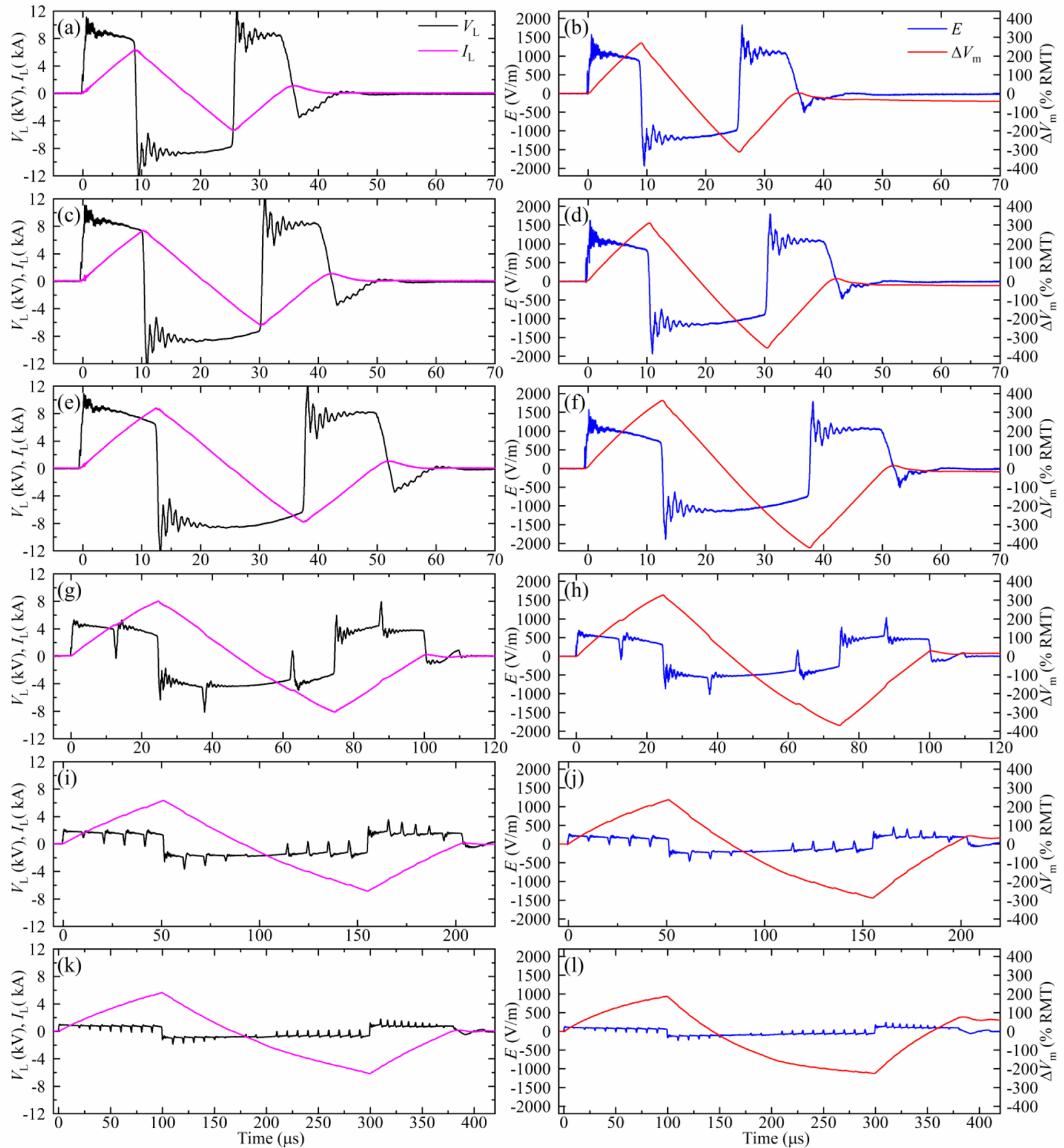
Measured coil current IL, coil voltage VL, electric field E, and estimated neural depolarization ∆Vm of positive biphasic pulses with VCref = 1100 V and various widths: (a), (b) 33 μs; (c), (d) 40 μs; (e), (f) 50 μs; (g), (h) 100 μs; (i), (j) 200 μs; (k), (l) 400 μs. These pulses use the module switching schemes described in figure 3: the pulses in (a)–(f) are generated with all modules connected in series, and the remaining rows correspond to the 5+5, 2+2+2+2+2, and 1+1+1+1+1+1+1+1+1+1 sequential module activation schemes, respectively.
Figures 6(g)–(h) demonstrate a 100 μs positive biphasic pulse generated with the 5+5 scheme, where the two module groups are sequentially activated for 12.5 μs to drive the coil with ±5 kV. Similarly, figures 6 (i)–(l) demonstrate 200 μs and 400 μs positive biphasic pulses using the 2+2+2+2+2 and 1+1+1+1+1+1+1+1+1+1 schemes, respectively, where each group of modules is on for 10 μs. These sequential module activation schemes enable markedly longer near-rectangular pulses than could be achieved by a single module or series connected modules.
The estimated neural membrane depolarization ∆Vm for all pulses in figure 6 exceeds 200% RMT, suggesting that these pulses would produce suprathreshold stimulation in most subjects.
In figures 6 (g)–(l), brief (< 1.5 μs) voltage and associated electric field spikes occur during the modules’ switching due to the small differences of the switching speed between the modules. Nevertheless, these spikes are too brief to significantly affect the neural membrane potential, as confirmed by the ∆Vm traces.
4.3. High-amplitude ultrabrief monophasic and biphasic pulses
While figure 6 illustrated only positive biphasic magnetic pulses, figure 7 demonstrates also high-amplitude ultrabrief (8.25 μs initial phase) monophasic and biphasic pulses of both polarities. This illustrates the flexibility of the MM-TMS device, including electronic pulse polarity control.
Figure 7.
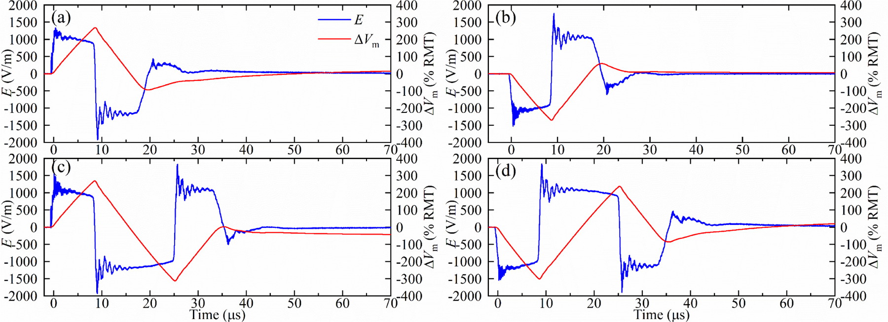
Measured electric field E and estimated neural depolarization ∆Vm of (a) positive and (b) negative 16.5 μs monophasic pulse, and (c) positive and (d) negative 33 μs biphasic pulse for VCref = 1100 V.
Further, by bypassing all the modules during a pulse, the prototype can insert a zero-voltage phase (interphase) with a controllable duration between the negative and positive electric field phases, which can reduce the neural activation threshold without increasing the peak coil current [52–55]. Figure 8 demonstrates the four pulses configurations from figure 7 but with interphases, where each pulse has an initial phase of 8.25 μs duration and an interphase of 8.5 μs.
Figure 8.
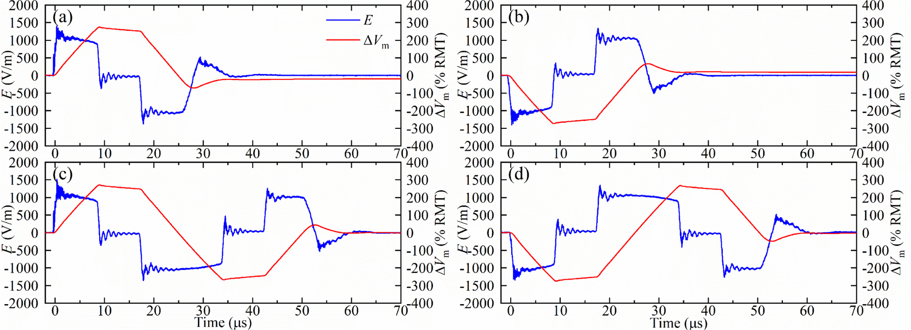
Measured electric field E and estimated neural depolarization ∆Vm of (a) positive and (b) negative 25 μs monophasic pulse with an 8.5 μs interphase, and (c) positive and negative (d) 50 μs biphasic pulse with 8.5 μs interphases for with VCref = 1100 V. The interphases cause the coil current to be approximately trapezoidal.
4.4. Short-interval paired pulses
The MM-TMS device’s unprecedented control over pulse parameters and its fundamentally energy-lossless topology allow the generation of paired-pulse protocols with various pulse shapes that conventionally require the outputs of two devices to be combined. The device can instantaneously increase the output amplitude from one pulse to the next by adding more modules in series, generating paired pulses with different stimulation strength.
Figures 9(a) and 9(b) illustrate this capability with a pair of monophasic positive pulses delivered with a short inter-stimulus interval (1 ms) with the stimulation strength increasing by 25% and 34%, respectively, for the second compared to the first pulse. This is achieved by connecting all ten modules in series for the second pulse while connecting only seven and six modules in series, respectively, for the first pulse.
Figure 9.
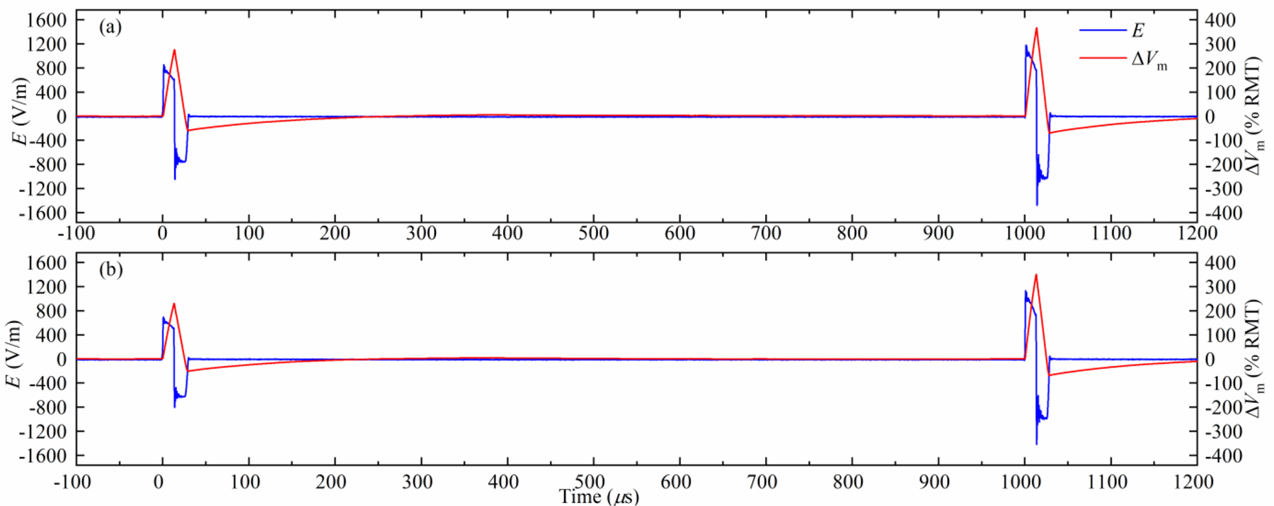
Pair of positive monophasic pulses delivered with a short interstimulus interval (1 ms). (a) The first pulse has a lower stimulation strength than the second pulse by 25%. (b) The first pulse has a lower stimulation strength than the second pulse by 36%. A longer, 3 ms interstimulus interval is illustrated in supplementary figure S11.
4.5. Amplitude-modulated sinusoidal polyphasic pulses
The capability of MM-TMS to generate relatively complex pulse shapes is illustrated in figure 10 with sinusoidal polyphasic pulses with a Gaussian envelope. Compared to a conventional polyphasic pulse with a flat envelope [30, 31], these pulses reduce the subharmonic sideband in the spectrum of the coil current, which could improve the acoustic performance of polyphasic pulses, as discussed in the following sections.
Figure 10.
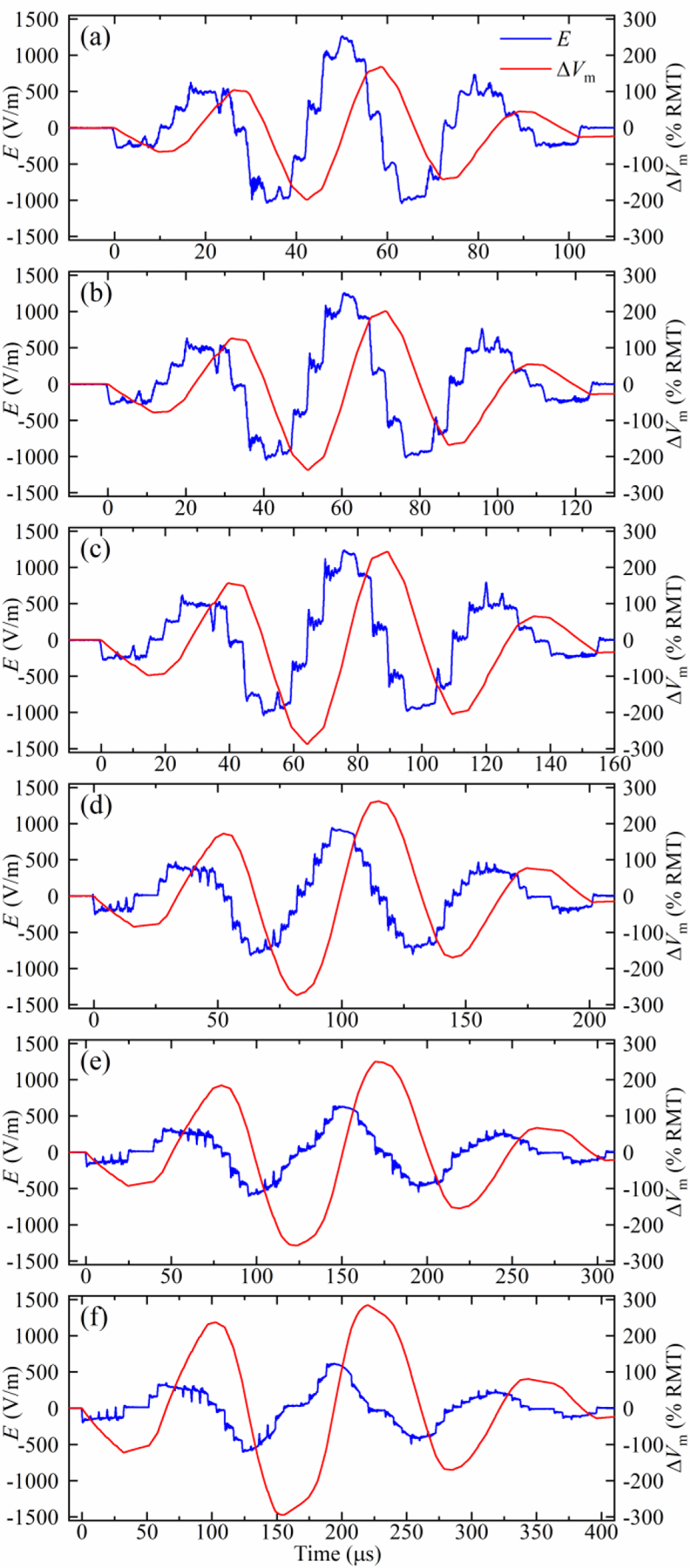
Measured electric field E and estimated neural membrane depolarization ∆Vm of the polyphasic pulses with Gaussian amplitude envelope with fundamental frequency of approximately (a) 30 kHz, (b) 25 kHz, (c) 20 kHz, (d) 15 kHz, (e) 10 kHz, and (f) 7.5 kHz. The initial module voltage VCref was selected so that the coil current during hard commutation did not exceed 6 kA.
4.6. Coil sound reduction
Since the sound emitted by a TMS coil is driven by electromagnetic forces, figure 11 shows spectral plots of the coil current and its square for representative MM-TMS pulses. In typical TMS applications, where there is no external magnetic field, the Lorentz forces within the coil are proportional to the cross product of the magnetic field and the current density, which is proportional to the square of the coil current. In specialized applications of TMS in the strong magnetic field of an MRI scanner, there are also Lorentz forces directly proportional to the coil current [56]. As expected, the coil current pulses have a spectral peak at the dominant pulse frequency, whereas the current squared displays peaks at twice that frequency.
Figure 11.
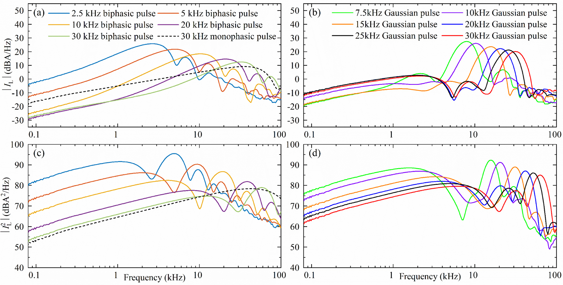
Smoothed 1/24-octave spectra of (a), (b) the measured coil current and (c), (d) the square of the coil current of selected biphasic rectangular pulses and the briefest monophasic rectangular pulse (left) as well as the polyphasic sinusoidal pulses with Gaussian amplitude envelope (right). The stimulation strength of each pulse was normalized to 167% average RMT.
Figures 12 and 13 as well as supplementary figures S13 and S14 show results of the acoustic recordings of the coil sound, which had the expected dependency on pulse duration. Figure 13 summarizes the pulse loudness for the various MM-TMS pules types illustrated in this paper. For matched estimated membrane depolarization based on the simplified linear first-order approximation—which has to be used with caution—briefer pulses were less loud than longer pulses. Further, the monophasic pulses were less loud than the biphasic pulses, which, in turn, were less loud than the Gaussian polyphasic pulses. The difference between monophasic and biphasic pulses was larger for briefer pulses, as, predictably, the biphasic pulses lost their depolarization efficiency advantage compared to monophasic pulses. Extrapolated to 5 cm from the coil surface, the DCC* coil with the briefest 17 µs monophasic pulse at 167% RMT had a peak sound pressure level (SPL) of 80 dB(Z) which is 32–55 dB lower than that of commercial TMS coils [2] and 14 dB lower than that of the DCC* coil with a conventional biphasic TMS pulse [42]. The continuous sound level (SL) for a simulated 20 Hz repetitive TMS train was 64 dB(A), which is 26–45 dB less than that of commercial coils and 13 dB less than that of the DCC* coil with a conventional TMS pulse.
Figure 12.
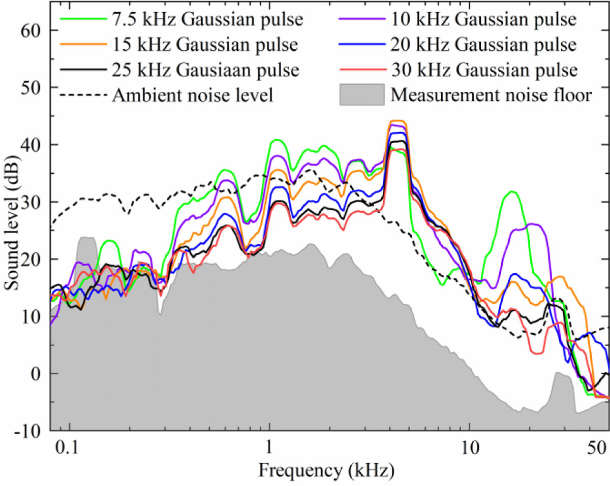
Smoothed 1/24-octave sound spectra of selected polyphasic sinusoidal pulses with Gaussian amplitude envelope. The sound has notable coil-specific components at 600, 1100, 2000, 2600, and 4300 Hz, and a pulse-specific component at twice the characteristic frequency of each pulse (15, 20, 30, and 40 kHz, respectively; the peaks for the two highest frequency pulses, 50 and 60 kHz, were above the recording bandwidth). The level of coil-specific components depends on pulse duration, and is in general lower for briefer pulses.
Figure 13.
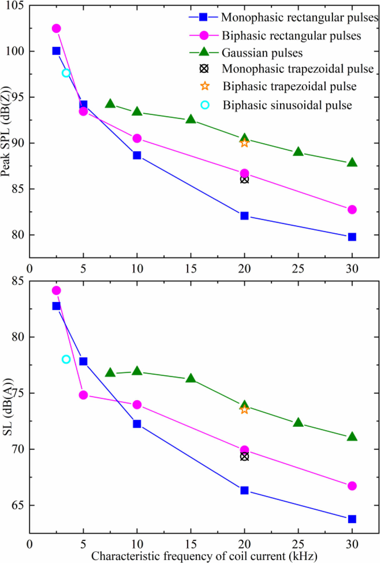
Peak sound pressure level (SPL) and sound level (SL) for various pulses generated by MM-TMS with the DCC* coil. SL is given for a simulated 20 Hz repetitive TMS train and both SPL and SL are extrapolated to 5 cm from the coil surface for pulse amplitude of 167% average RMT.
The sound spectra of the different pulse waveforms show two mechanisms that explain this reduction. The Gaussian pulse acoustic spectra in figure 12 show that the characteristic sound frequency of a TMS pulse is twice the characteristic electric field frequency. This is expected, as the Lorentz force is proportional to the coil current squared. Consequently, both briefer pulses and high-frequency Gaussian pulses push this part of the excitation forces and the sound energy out of the human hearing range, which is below 20 kHz. The attenuation is further amplified by the DCC* coil which was designed to work as an acoustic low-pass filter [42]. Further, for pulses with characteristic frequency much greater than the dominant modes of the DCC* (namely, the long and short modes of the winding block at around 2 and 4 kHz, respectively), briefer pulses have less subharmonic frequency content, reducing the sound intensity of these modes. This causes brief monophasic pulses to be quieter than their biphasic or Gaussian counterparts with matched frequency content (see supplementary figures S13 and S14 for the monophasic and biphasic spectra, respectively).
The sound differences between the pulses can be readily explained by differences in their squared-coil-current spectra (figure 11(c), (d)). The difference between the sound spectrum and the squared-coil-current spectrum is approximately a frequency-dependent constant factor—the acoustic transfer function of the coil. Using leave-one-out analysis on the pairs of sound and squared-current spectra, the geometric mean of their computed transfer functions can predict the left out sound spectrum from the corresponding squared-current spectrum with a mean prediction error of 2.4 dB and 95% percentile prediction error of 5.2 dB between 1 and 40 kHz. Below 1 kHz and above 40 kHz, the prediction accuracy deteriorates as the sound spectra hit the measurement noise floor. Notably, the 5 kHz biphasic pulse and the 7.5 kHz Gaussian envelope pulse were quieter than expected from the general trend for pulse durations in figure 13. This reduction in sound is quantitatively explained by the estimated acoustic transfer function of the coil, as these two pulses have a minimum in their squared-coil-current spectra near the main sound-producing resonant frequency of the DCC* coil at around 4–5 kHz. It might be possible to further deepen this minimum and to tune it more accurately to the relatively narrowband resonant mode of the coil. Alternatively, it might be possible to generate a similar minimum for a briefer pulse with overall reduction in the squared-current spectrum in the hearing range.
5. Discussion
This paper presented a novel MM-TMS device with a wide and flexibly controlled output range of suprathreshold pulses. The MM-TMS device was able to generate the briefest TMS pulses reported to date, with biphasic duration as short as 33 μs. These high-voltage ultrabrief pulses had estimated neural membrane depolarization exceeding 300% RMT, suggesting suprathreshold stimulation strength. However, as noted earlier, the neural activation model used in this work has to be interpreted only as a rough approximation for the effective stimulation strength, since it simplifies significantly the neural dynamics and may underestimate the thresholds for ultrabrief pulses [48, 49]. In the future, these stimulation strength estimates can be replaced by empirical motor thresholds or more complex neural response models.
The MM-TMS device can generate a wider range of pulse shapes and widths (e.g., 33–400 μs biphasic) than previously possible [8–11, 29]. The ten-module MM-TMS device allows 21 output voltage levels in a pulse, which enables the generation of near-sinusoidal, near-rectangular, and more complex pulse shapes, not available in other TMS devices. We provided examples of complex polyphasic pulses with a Gaussian amplitude envelope and a wide range of pulse widths (99–400 μs). We had hypothesized that such pulses may reduce the pulse sound [23]. Our sound measurements in combination with the simplified linear threshold model suggest that the Gaussian envelope pulses with the specific carrier and envelope parameters selected here are louder than both the biphasic and monophasic pulses with the same characteristic frequency. The relative loudness of the Gaussian envelope pulses is due to a significant low-frequency sideband of the squared coil current, which is the dominant driving factor for the coil sound. However, these comparisons may be confounded since the simplified neural depolarization model is not able to correctly estimate the threshold for polyphasic pulses [30, 31, 50, 57]. Moreover, we did not optimize any parameters of the Gaussian pulses such as the width of the envelope. Worth noting is that the Gaussian envelope pulses are likely quieter than matched polyhasic pulses with a flat envelope [30, 31], although this was not tested expeirmentally. Finally, our measurements suggest that the coil sound reduction could be optimized by coordinating the spectra of the driving electromagnetic forces and the coil acoustic transfer function, for example by matching peaks in one to minima in the other.
The MM-TMS device implements efficient energy recycling since most of the pulse energy is recovered back to the capacitors. This, combined with the unprecedented flexible control over the pulse shape, enables a single device to generate rapid pulses sequences with different shapes for each pulse, which conventionally require two or more TMS devices to be combined. Importantly, the pulse amplitude of each pulse can be adjusted up or down independently of the amplitude of the prior pulse, which is critical for paired-pulse protocols. The efficient energy recycling in MM-TMS supports the generation of high-frequency repetitive TMS trains, as has been demonstrated for single H-bridge modules or similar topologies [9, 11, 12, 37]. In this work, we tested only slow pulse repetition rates (≤ 1 Hz) or closely spaced pulse pairs and not long rapid trains since the electromechanical charging relays Sg and Sp have limited life; in their place, semiconductor switches can be used for more reliable repeated topping off of the capacitor charge during the trains, as is customary in conventional TMS chargers.
Notably, except for the 1+1+1+1+1+1+1+1+1+1 sequential switching scheme intended for very long pulses, the MM-TMS device drives differentially the two coil terminals with a pair of voltages of equal magnitude but opposite polarity, leading to a zero common-mode voltage of the coil and zero voltage at the center of the conventional figure-of-8 TMS coil configuration at any instant during a pulse [27]. This could, in principle, reduce the artifact in concurrent EEG and EMG recordings resulting from high-voltage capacitive coupling between the TMS coil and the subject’s body and recording electronics.
Finally, a limitation of the MM-TMS circuit topology is that it allows only series or bypass connections among the modules. Thus, the total capacitance across the modules cannot be utilized at low output voltage levels since the modules cannot be connected in parallel. The MM-TMS topology can, however, be modified to add parallel connectivity [39]. While this is a compelling direction for future research, we did not pursue it in this work due to the added complexity of implementing and controlling the required additional IGBT switches.
6. Conclusion
We developed the first suprathreshold TMS device using a modular multilevel circuit topology at full TMS energy levels. The MM-TMS device allows unprecedented control of the pulse shape, amplitude, and width, which could enable improved and novel research, diagnostic, and therapeutic protocols, including ones with reduced acoustic noise.
Supplementary Material
Acknowledgments
Research reported in this publication was supported by the National Institute of Mental Health of the National Institutes of Health under award numbers R01MH111865 and RF1MH124943 as well as by hardware donations from Magstim. The content is solely the responsibility of the authors and does not necessarily represent the official views of the National Institutes of Health.
L. M. Koponen, S. M. Goetz, and A. V. Peterchev are inventors on patents and patent applications on TMS technology, including the coil technology described in this paper. S. M. Goetz is also inventor on patents covering aspects of the TMS pulse generator. Related to magnetic stimulation technology, S. M. Goetz has received research funding and patent application support from Magstim, and A. V. Peterchev has received research funding, travel support, patent royalties, consulting fees, equipment loans, hardware donations, and/or patent application support from Rogue Research, Magstim, MagVenture, Neuronetics, BTL Industries, and Advise Connect Inspire.
References
- [1].Koponen LM and Peterchev AV 2020. Transcranial magnetic stimulation: principles and applications Neural Engineering 3rd ed, ed He B: Springer Nature Switzerland AG; pp 245–70 [Google Scholar]
- [2].Koponen LM, Goetz SM, Tucci DL and Peterchev AV 2020. Sound comparison of seven TMS coils at matched stimulation strength Brain Stimul 13 873–80 [DOI] [PMC free article] [PubMed] [Google Scholar]
- [3].Goetz SM, Lisanby SH, Murphy DLK, Price RJ, O’Grady G and Peterchev AV 2015. Impulse Noise of Transcranial Magnetic Stimulation: Measurement, Safety, and Auditory Neuromodulation Brain Stimul 8 161–3 [DOI] [PubMed] [Google Scholar]
- [4].Rossi S, Antal A, Bestmann S, Bikson M, Brewer C, Brockmöller J, Carpenter LL, Cincotta M, Chen R, Daskalakis JD, Di Lazzaro V, Fox MD, George MS, Gilbert D, Kimiskidis VK, Koch G, Ilmoniemi RJ, Pascal Lefaucheur J, Leocani L, Lisanby SH, Miniussi C, Padberg F, Pascual-Leone A, Paulus W, Peterchev AV, Quartarone A, Rotenberg A, Rothwell J, Rossini PM, Santarnecchi E, Shafi MM, Siebner HR, Ugawa Y, Wassermann EM, Zangen A, Ziemann U and Hallett M 2021. Safety and recommendations for TMS use in healthy subjects and patient populations, with updates on training, ethical and regulatory issues: Expert Guidelines Clin Neurophysiol 132 269–306 [DOI] [PMC free article] [PubMed] [Google Scholar]
- [5].Goetz SM, Murphy DLK and Peterchev AV 2014. Transcranial Magnetic Stimulation Device With Reduced Acoustic Noise IEEE Mag Lett 5 1–4 [Google Scholar]
- [6].Goetz SM and Deng Z-D 2017. The development and modelling of devices and paradigms for transcranial magnetic stimulation International Review of Psychiatry 29 115–45 [DOI] [PMC free article] [PubMed] [Google Scholar]
- [7].Peterchev AV, Deng Z-D and Goetz SM 2015. Advances in transcranial magnetic stimulation technology Brain Stimulation: Methodologies and Interventions ed, ed Reti IM Hoboken, NJ, USA: Wiley Blackwell; pp 165–89 [Google Scholar]
- [8].Peterchev AV, Jalinous R and Lisanby SH 2008. A transcranial magnetic stimulator inducing near-rectangular pulses with controllable pulse width (cTMS) IEEE Trans Biomed Eng 55 257–66 [DOI] [PMC free article] [PubMed] [Google Scholar]
- [9].Peterchev AV, Murphy DL and Lisanby SH 2011. Repetitive transcranial magnetic stimulator with controllable pulse parameters J Neural Eng 8 036016. [DOI] [PMC free article] [PubMed] [Google Scholar]
- [10].Peterchev AV, DʼOstilio K, Rothwell JC and Murphy DL 2014. Controllable pulse parameter transcranial magnetic stimulator with enhanced circuit topology and pulse shaping J Neural Eng 11 056023. [DOI] [PMC free article] [PubMed] [Google Scholar]
- [11].Gattinger N, Moßnang G and Gleich B 2012. flexTMS—A Novel Repetitive Transcranial Magnetic Stimulation Device With Freely Programmable Stimulus Currents IEEE Trans Biomed Eng 59 1962–70 [DOI] [PubMed] [Google Scholar]
- [12].Sorkhabi MM, Benjaber M, Wendt K, West TO, Rogers DJ and Denison T 2021. Programmable Transcranial Magnetic Stimulation: A Modulation Approach for the Generation of Controllable Magnetic Stimuli IEEE Trans Biomed Eng 68 1847–58 [DOI] [PMC free article] [PubMed] [Google Scholar]
- [13].Peterchev AV, Goetz SM, Westin GG, Luber B and Lisanby SH 2013. Pulse width dependence of motor threshold and input-output curve characterized with controllable pulse parameter transcranial magnetic stimulation Clin Neurophysiol 124 1364–72 [DOI] [PMC free article] [PubMed] [Google Scholar]
- [14].D’Ostilio K, Goetz SM, Hannah R, Ciocca M, Chieffo R, Chen JA, Peterchev AV and Rothwell JC 2016. Effect of coil orientation on strength-duration time constant and I-wave activation with controllable pulse parameter transcranial magnetic stimulation Clin Neurophysiol 127 675–83 [DOI] [PMC free article] [PubMed] [Google Scholar]
- [15].Hannah R and Rothwell JC 2017. Pulse Duration as Well as Current Direction Determines the Specificity of Transcranial Magnetic Stimulation of Motor Cortex during Contraction Brain Stimul 10 106–15 [DOI] [PMC free article] [PubMed] [Google Scholar]
- [16].Casula EP, Rocchi L, Hannah R and Rothwell JC 2018. Effects of pulse width, waveform and current direction in the cortex: A combined cTMS-EEG study Brain Stimul 11 1063–70 [DOI] [PubMed] [Google Scholar]
- [17].Sommer M, Ciocca M, Chieffo R, Hammond P, Neef A, Paulus W, Rothwell JC and Hannah R 2018. TMS of primary motor cortex with a biphasic pulse activates two independent sets of excitable neurones Brain Stimul 11 558–65 [DOI] [PMC free article] [PubMed] [Google Scholar]
- [18].Hannah R, Cavanagh SE, Tremblay S, Simeoni S and Rothwell JC 2018. Selective Suppression of Local Interneuron Circuits in Human Motor Cortex Contributes to Movement Preparation J Neurosci 38 1264–76 [DOI] [PMC free article] [PubMed] [Google Scholar]
- [19].Hannah R, Rocchi L, Tremblay S, Wilson E and Rothwell JC 2020. Pulse width biases the balance of excitation and inhibition recruited by transcranial magnetic stimulation Brain Stimul 13 536–8 [DOI] [PubMed] [Google Scholar]
- [20].Goetz SM, Luber B, Lisanby SH, Murphy DL, Kozyrkov IC, Grill WM and Peterchev AV 2016. Enhancement of Neuromodulation with Novel Pulse Shapes Generated by Controllable Pulse Parameter Transcranial Magnetic Stimulation Brain Stimul 9 39–47 [DOI] [PMC free article] [PubMed] [Google Scholar]
- [21].Halawa I, Shirota Y, Neef A, Sommer M and Paulus W 2019. Neuronal tuning: Selective targeting of neuronal populations via manipulation of pulse width and directionality Brain Stimul 12 1244–52 [DOI] [PubMed] [Google Scholar]
- [22].Peterchev AV, Luber B, Westin GG and Lisanby SH 2017. Pulse Width Affects Scalp Sensation of Transcranial Magnetic Stimulation Brain Stimul 10 99–105 [DOI] [PMC free article] [PubMed] [Google Scholar]
- [23].Peterchev AV, Murphy DLK and Goetz SM 2015. Quiet transcranial magnetic stimulation: Status and future directions In: IEEE Eng Med Biol Conf, pp 226–9 [DOI] [PubMed] [Google Scholar]
- [24].Rossini PM, Burke D, Chen R, Cohen LG, Daskalakis Z, Di Iorio R, Di Lazzaro V, Ferreri F, Fitzgerald PB, George MS, Hallett M, Lefaucheur JP, Langguth B, Matsumoto H, Miniussi C, Nitsche MA, Pascual-Leone A, Paulus W, Rossi S, Rothwell JC, Siebner HR, Ugawa Y, Walsh V and Ziemann U 2015. Non-invasive electrical and magnetic stimulation of the brain, spinal cord, roots and peripheral nerves: Basic principles and procedures for routine clinical and research application. An updated report from an I.F.C.N. Committee Clin Neurophysiol 126 1071–107 [DOI] [PMC free article] [PubMed] [Google Scholar]
- [25].Cash RF, Ziemann U, Murray K and Thickbroom GW 2010. Late cortical disinhibition in human motor cortex: a triple-pulse transcranial magnetic stimulation study J Neurophysiol 103 511–8 [DOI] [PubMed] [Google Scholar]
- [26].Hamada M, Terao Y, Hanajima R, Shirota Y, Nakatani-Enomoto S, Furubayashi T, Matsumoto H and Ugawa Y 2008. Bidirectional long-term motor cortical plasticity and metaplasticity induced by quadripulse transcranial magnetic stimulation J Physiol 586 3927–47 [DOI] [PMC free article] [PubMed] [Google Scholar]
- [27].Goetz SM, Pfaeffl M, Huber J, Singer M, Marquardt R and Weyh T 2012. Circuit topology and control principle for a first magnetic stimulator with fully controllable waveform IEEE Eng Med Biol Conf 34 4700–3 [DOI] [PubMed] [Google Scholar]
- [28].Weyh T and Götz SM 2013 Magnetic stimulation having a freely selectable pulse shape US Pat Trade Off US 2013/0030239 A1
- [29].Barker AT, Garnham CW and Freeston IL 1991. Magnetic nerve stimulation: the effect of waveform on efficiency, determination of neural membrane time constants and the measurement of stimulator output Electroencephalogr Clin Neurophysiol Suppl 43 227–37 [PubMed] [Google Scholar]
- [30].Pechmann A, Delvendahl I, Bergmann TO, Ritter C, Hartwigsen G, Gleich B, Gattinger N, Mall V and Siebner HR 2012. The number of full-sine cycles per pulse influences the efficacy of multicycle transcranial magnetic stimulation Brain Stimul 5 148–54 [DOI] [PubMed] [Google Scholar]
- [31].Emrich D, Fischer A, Altenhofer C, Weyh T, Helling F, Goetz S, Brielmeier M and Matiasek K 2012. Muscle force development after low-frequency magnetic burst stimulation in dogs Muscle Nerve 46 954–6 [DOI] [PubMed] [Google Scholar]
- [32].Chaieb L, Antal A and Paulus W 2011. Transcranial alternating current stimulation in the low kHz range increases motor cortex excitability Restor Neurol Neurosci 29 167–75 [DOI] [PubMed] [Google Scholar]
- [33].Chaieb L, Antal A, Pisoni A, Saiote C, Opitz A, Ambrus GG, Focke N and Paulus W 2014. Safety of 5 kHz tACS Brain Stimul 7 92–6 [DOI] [PubMed] [Google Scholar]
- [34].Grossman N, Bono D, Dedic N, Kodandaramaiah SB, Rudenko A, Suk HJ, Cassara AM, Neufeld E, Kuster N, Tsai LH, Pascual-Leone A and Boyden ES 2017 Noninvasive Deep Brain Stimulation via Temporally Interfering Electric Fields Cell 169 1029–41.e16 [DOI] [PMC free article] [PubMed] [Google Scholar]
- [35].Mirzakhalili E, Barra B, Capogrosso M and Lempka SF 2020. Biophysics of Temporal Interference Stimulation Cell Syst 11 557–72.e5 [DOI] [PubMed] [Google Scholar]
- [36].Sheltraw D, Inglis B, Labruna L and Ivry R 2021. Comparing the electric fields of Transcranial electric and magnetic perturbation J Neural Eng [DOI] [PMC free article] [PubMed] [Google Scholar]
- [37].Jung NH, Gleich B, Gattinger N, Hoess C, Haug C, Siebner HR and Mall V 2016. Quadri-Pulse Theta Burst Stimulation using Ultra-High Frequency Bursts - A New Protocol to Induce Changes in Cortico-Spinal Excitability in Human Motor Cortex PLoS One 11 e0168410. [DOI] [PMC free article] [PubMed] [Google Scholar]
- [38].Wu B and Narimani M 2017. Cascaded H-Bridge Multilevel Inverters High-Power Converters and AC Drives 2nd ed, ed Wu B and Narimani M: IEEE; pp 119–22 [Google Scholar]
- [39].Goetz SM, Peterchev AV and Weyh T 2015. Modular Multilevel Converter With Series and Parallel Module Connectivity: Topology and Control IEEE Trans Power Electron 30 203–15 [Google Scholar]
- [40].Riehl M 2008. TMS stimulator design Oxford Handbook of Transcranial Stimulation ed, ed Wassermann EM, et al. Oxford: Oxford University Press; pp 13–23 [Google Scholar]
- [41].Grbovic PJ 2008. An IGBT Gate Driver for Feed-Forward Control of Turn-on Losses and Reverse Recovery Current IEEE Trans Power Electron 23 643–52 [Google Scholar]
- [42].Koponen LM, Goetz S and Peterchev AV 2021. Double-containment coil with enhanced winding mounting for transcranial magnetic stimulation with reduced acoustic noise IEEE Trans Biomed Eng 68 2233–40 [DOI] [PMC free article] [PubMed] [Google Scholar]
- [43].Goetz SM, Truong CN, Gerhofer MG, Peterchev AV, Herzog HG and Weyh T 2013. Analysis and optimization of pulse dynamics for magnetic stimulation PLoS One 8 e55771. [DOI] [PMC free article] [PubMed] [Google Scholar]
- [44].Giesselmann M, Palmer B, Neuber A and Donlon J 2005. High Voltage Impulse Generator Using HV-IGBTs In: IEEE Pulsed Power Conf, pp 763–6 [Google Scholar]
- [45].Trivedi M and Shenai K 1997. Modeling the turn-off of IGBT’s in hard- and soft-switching applications IEEE Trans Electron Dev 44 887–93 [Google Scholar]
- [46].Petterteig A, Lode J and Undeland TM 1991. IGBT turn-off losses for hard switching and with capacitive snubbers IEEE Ind Appl Soc Ann Meeting 1501–7 2 [Google Scholar]
- [47].UL. UL 60601–1 Medical Electrical Equipment, Part 1: General Requirements for Safety 2003
- [48].Dean D and Lawrence PD 1985. Optimization of Neural Stimuli Based Upon a Variable Threshold Potential IEEE Trans Biomed Eng BME-32 8–14 [DOI] [PubMed] [Google Scholar]
- [49].Moffitt MA, Mcintyre CC and Grill WM 2004. Prediction of myelinated nerve fiber stimulation thresholds: limitations of linear models IEEE Trans Biomed Eng 51 229–36 [DOI] [PubMed] [Google Scholar]
- [50].Goetz SM, Weyh T and Herzog H 2009. Analysis of a magnetic stimulation system: Magnetic harmonic multi-cycle stimulation (MHMS) In: Int Conf Biomed Pharm Eng, pp 1–6 [Google Scholar]
- [51].Nieminen JO, Koponen LM and Ilmoniemi RJ 2015. Experimental Characterization of the Electric Field Distribution Induced by TMS Devices Brain Stimul 8 582–9 [DOI] [PubMed] [Google Scholar]
- [52].Koponen LM, Nieminen JO, Mutanen TP and Ilmoniemi RJ 2018. Noninvasive extraction of microsecond-scale dynamics from human motor cortex Hum Brain Mapp 39 2405–11 [DOI] [PMC free article] [PubMed] [Google Scholar]
- [53].Hiwaki O and Ueno S 1993. The Property of Nerve Excitation Elicited by Magnetic Stimulation of Peripheral Nerve IEEE Transl J Mag Japan 8 326–32 [Google Scholar]
- [54].Hiwaki O and Ueno S 1994. Nerve Excitation Properties in Magnetic Stimulation by Trapezoidal Magnetic Fields IEEE Transl J Mag Japan 9 148–52 [Google Scholar]
- [55].Hiwaki O and Ueno S 1992. Nerve excitation processes stimulated by trapezoidal magnetic fields In: IEEE Eng Med Biol Conf, pp 1614–5 [Google Scholar]
- [56].Crowther LJ, Porzig K, Hadimani RL, Brauer H and Jiles DC 2012. Calculation of Lorentz Forces on Coils for Transcranial Magnetic Stimulation During Magnetic Resonance Imaging IEEE Trans Mag 48 4058–61 [Google Scholar]
- [57].Claus D, Murray NMF, Spitzer A and Flügel D 1990. The influence of stimulus type on the magnetic excitation of nerve structures Electroencephalography and Clinical Neurophysiology 75 342–9 [DOI] [PubMed] [Google Scholar]
Associated Data
This section collects any data citations, data availability statements, or supplementary materials included in this article.


