Abstract
Mobility disabilities are prominent in society with wide-ranging deficits, motivating modular, partial-assist, lower-limb exoskeletons for this heterogeneous population. This paper introduces the Modular Backdrivable Lower-limb Unloading Exoskeleton (M-BLUE), which implements high torque, low mechanical impedance actuators on commercial orthoses with sheet metal modifications to produce a variety of hip- and/or knee-assisting configurations. Benchtop system identification verifies the desirable backdrive properties of the actuator, and allows for torque prediction within ±0.4 Nm. An able-bodied human subject experiment demonstrates that three unilateral configurations of M-BLUE (hip only, knee only, and hip-knee) with a simple gravity compensation controller can reduce muscle EMG readings in a lifting and lowering task relative to the bare condition. Reductions in mean muscular effort and peak muscle activation were seen across the primary squat musculature (excluding biceps femoris), demonstrating the potential to reduce fatigue leading to poor lifting posture. These promising results motivate applications of M-BLUE to additional populations, and the expansion of M-BLUE to bilateral and ankle configurations.
Index Terms—: Prosthetics and Exoskeletons, Wearable Robotics
I. Introduction
ONE in eight adults in the U.S. has a mobility impairment that limits their social activity, economic productivity, and quality of life [1]. These deficits often stem from advanced age, stroke, or musculoskeletal disorders. Most of these individuals have some voluntary control of their lower limbs, and thus require only partial assistance to overcome these deficits. However, no broadly applicable intervention fits this important need [2]. Conventional orthoses tend to immobilize rather than assist joints, causing side-effects that include compensatory movements, gait asymmetry, and overdependence on the device. In addition, most mobility aids (e.g., passive orthoses, canes, and walkers) cannot provide net-positive mechanical work to assist activities that require substantial muscular effort, including squatting, sit-to-stand, and stair ascent.
Emerging powered orthoses (i.e., exoskeletons) have the potential to restore normative leg biomechanics [2], but these devices have not been widely adopted in part because of their rigid joints, bulkiness, and population-specific designs. Commercial rehabilitation exoskeletons like those manufactured by Ekso Bionics, Indego, and ReWalk feature an integrated lower-body frame with a fixed set of actuators targeting specific joints for a specific patient population [3]–[5]. These devices are generally designed with actuators that prevent the user’s weight from backdriving the joint (i.e., the human rotating the motor) and enable large output torques to provide the complete limb function for a person with spinal cord injury [5] or severe stroke [6]. To minimize size and mass, these actuators are designed with small, low-torque, high-speed motors that require a large gear ratio (typically greater than 50:1 [7]) to achieve human-scale torques-velocity regimes. The motor’s inertia reflected through the transmission scales with the gear ratio squared, and friction from meshing parts gets similarly amplified [8]. This results in high mechanical impedance at the joint, which means the user cannot easily backdrive the actuator to move their joints. In this actuation paradigm, the user is typically forced to follow the robot’s pre-defined joint patterns rather than their own volition [9], though some devices like Indego [6] are more backdrivable than others.
Recent work has focused on augmenting voluntary motion with backdrivable powered orthoses [7], [10]–[15] and soft exosuits [16]–[18], achieving backdrivability in different ways. Load cells [16] or series elastic elements [19] can provide force feedback to control torque (as in B-Temia Keeogo [20]), but this tends to increase mechanical complexity and limit actuator torque bandwidth. The Honda [21] and Samsung [22] hip orthoses use a lower gear ratio to increase backdrivability at the cost of output torque (less than 10 Nm), motivating the use of emerging high-torque, backdrivable actuators called quasi-direct drive actuators. These actuators use high-torque “pancake” motors to achieve high output torques with low gear ratios (and thus low friction/inertia). Quasi-direct drive actuators have enabled legged robots to perform dynamic walking, running, and jumping with high control bandwidth, precise current-based torque control, energy regeneration, compliance to impacts, and reduced acoustic noise [8], [23], [24]. We recently implemented quasi-direct drive actuators in leg orthoses [7], [11], enabling the use of an emerging task-invariant control method called energy shaping [25], e.g., compensating body weight [26] and/or inertia. However, these backdrivable designs do not offer a reconfigurable solution for different use cases (i.e., different joints).
One of the first modular exoskeletons [27] adds a compliant actuator to conventional hip, knee, and ankle orthoses. Although this design allows different joint configurations, the use of series elasticity increases size and mass (1.4 kg per actuator). Additionally, its peak torque of 16.7 Nm may be insufficient for some use cases, such as compensating for the difference in knee torques between a safe squat lift and a risky stoop lift (around 30 Nm [28]) to prevent workplace injuries. Instead of modifying conventional orthoses, custom exoskeleton modules have been designed in [29] to provide substantial torque at the ankle (102 Nm), knee (69 Nm), and/or hip (102 Nm) for individuals with spinal cord injury. Although this system offers a trajectory-free neuromuscular control strategy, its backdrivability is limited by the use of series elasticity with large gear ratios (up to 100:1). The modular exoskeleton in [30] can achieve similar torques at the knee and hip, using a mix of custom and conventional orthotic components. This design does not have active torque sensing to compensate for its high gear ratio (up to 120:1), reducing torque control accuracy and backdrivability.
These prior works motivate our use of more backdrivable and compact quasi-direct drive actuators in the presented hip and/or knee system called the Modular Backdrivable Lower-limb Unloading Exoskeleton (M-BLUE). M-BLUE is designed to provide sufficient output torque to partially assist mild to moderate impairments, while having negligible backdrive torque to facilitate voluntary motion. We use the recently released T-Motor AK80–9 actuator (with a 9:1 internal transmission [31]) to improve upon our prior design [7] with a single-stage planetary gearset inside a torque-dense “pancake” Brushless DC motor, enabling higher output torque and lower backdrive in a smaller, lighter package. We extend this actuation paradigm to the modular design philosophy of [27], making simple aftermarket modifications to commercial hip and knee orthoses that can be replicated by clinicians. We focus on the hip and knee to avoid the complexity and expense of custom ankle orthosis designs [10], because commercial ankle-foot orthoses (made of carbon fiber or thermoplastic) tend to immobilize the ankle and are not amenable to actuation. We also implement a modular, trajectory-free, gravity-compensation control strategy to assist volitional motion at the hip and/or knee. Benchtop experiments demonstrate the lightweight actuator module (584 g) can produce up to 30 Nm with less than 2 Nm of dynamic backdrive torque during human-like walking motions. We demonstrate that the hip-only, knee-only, and hip-and-knee configurations reduce muscle activity during an able-bodied lifting and lowering experiment, suggesting the presented system can reduce muscular fatigue leading to risky lifting posture [32]. By leveraging the Dephy FASTER embedded system, the hip and knee modules can easily be interfaced with the custom Dephy ExoBoot system [10], [33] to enable ankle configurations in future work.
II. Design and Control
We developed a plug-and-play exoskeleton system for a wide variety of subjects and use cases (Fig. 1). We sought to accommodate users of a wide variety of heights, weights up to 250 lbs, and across the range of the adult lifespan. The following sections describe how the actuator and orthosis structure were chosen for broad use cases.
Fig. 1.
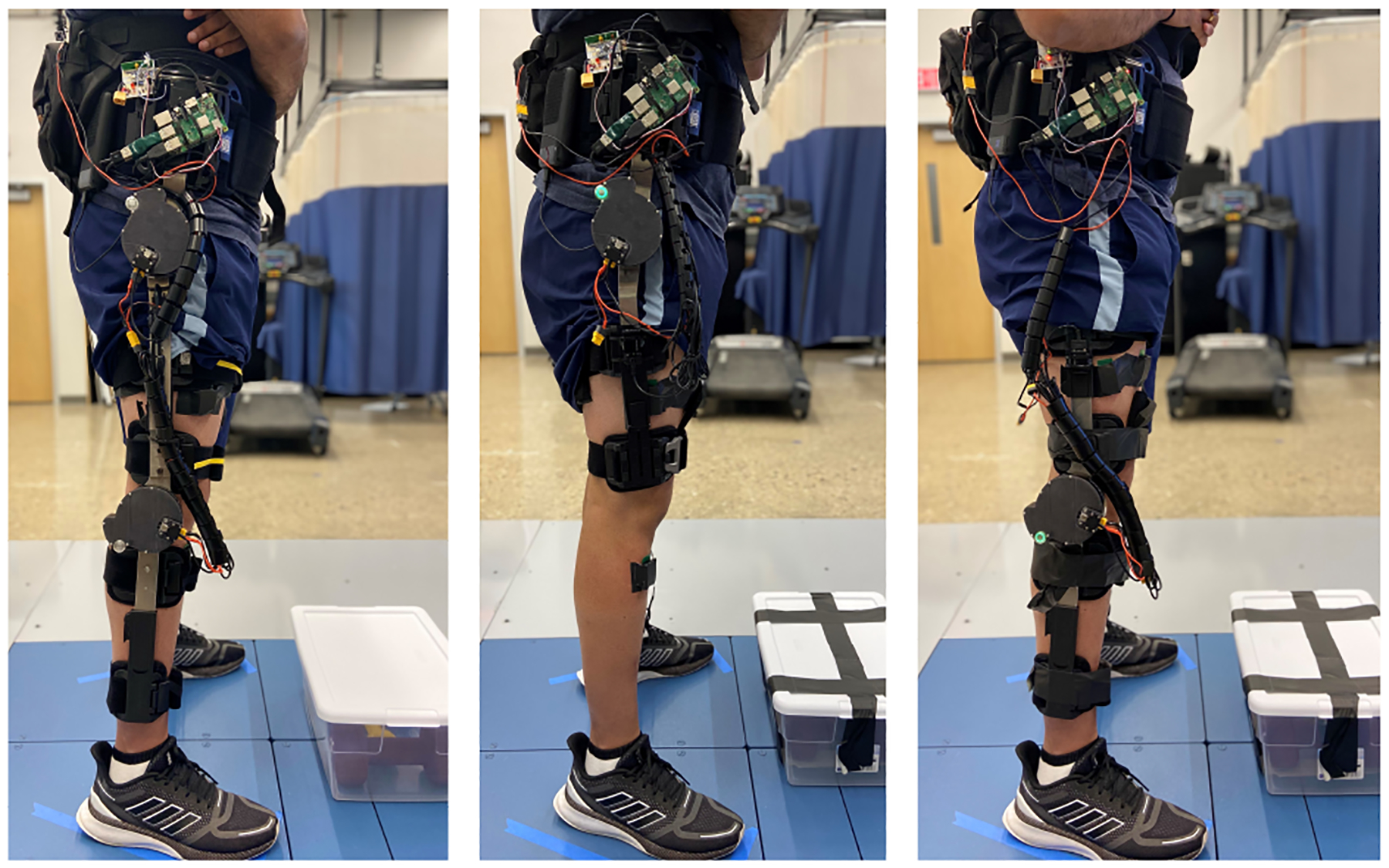
Hip-knee, hip only, and knee only configurations of modular powered orthoses during lifting and lowering experiment. Note that the EMG electrodes and top PCB (for wireless sync) are only for assessment purposes, and would be removed during normal use. The Raspberry Pi can be enclosed in a case.
A. Actuator Selection
When selecting an actuator for the hip and knee modules of M-BLUE, we sought to improve upon the performance of our prior knee exoskeleton [7] with respect to output torque (previously 24 Nm), reflected inertia (previously 200.9 kg·cm2), mass (previously 1.15 kg), and volume (previously 814 cm3 including heatsink). With these criteria in mind, we opted for the AK80–9 actuator (T-motor, China). Its high torque density, low gear ratio (9:1), low mass (485 g), low volume (233 cm3), and low cost ($580 USD) make it a suitable choice for our application. The actuator assembly sets a 9:1 planetary gear inside a wide diameter BLDC motor similar to those used in high-power electric quadcopters (see Fig. 2, [31]). Our previous study [34] on the thermal properties and performance of the T-motor U8-KV100, which is nearly identical to the electric motor inside the AK80–9 assembly, demonstrated its excellent torque/speed capabilities for legged robot applications. In particular, the analysis suggests that the actuator can provide torque up to 30 Nm, which is 25–50% of normative peak torque depending on the joint, task, and subject weight [35]. This torque output can 1) compensate for the difference in knee torque required for a safe squat lift (“lift with the knees”) compared to a riskier stoop lift posture (“lift with the back”) [28], 2) overcome the difference in knee moments between the affected and unaffected sides of an average individual with chronic stroke during sit to stand [36], and 3) reach the strength threshold needed to assist ageing individuals with activities of daily living (ADLs) [2].
Fig. 2.
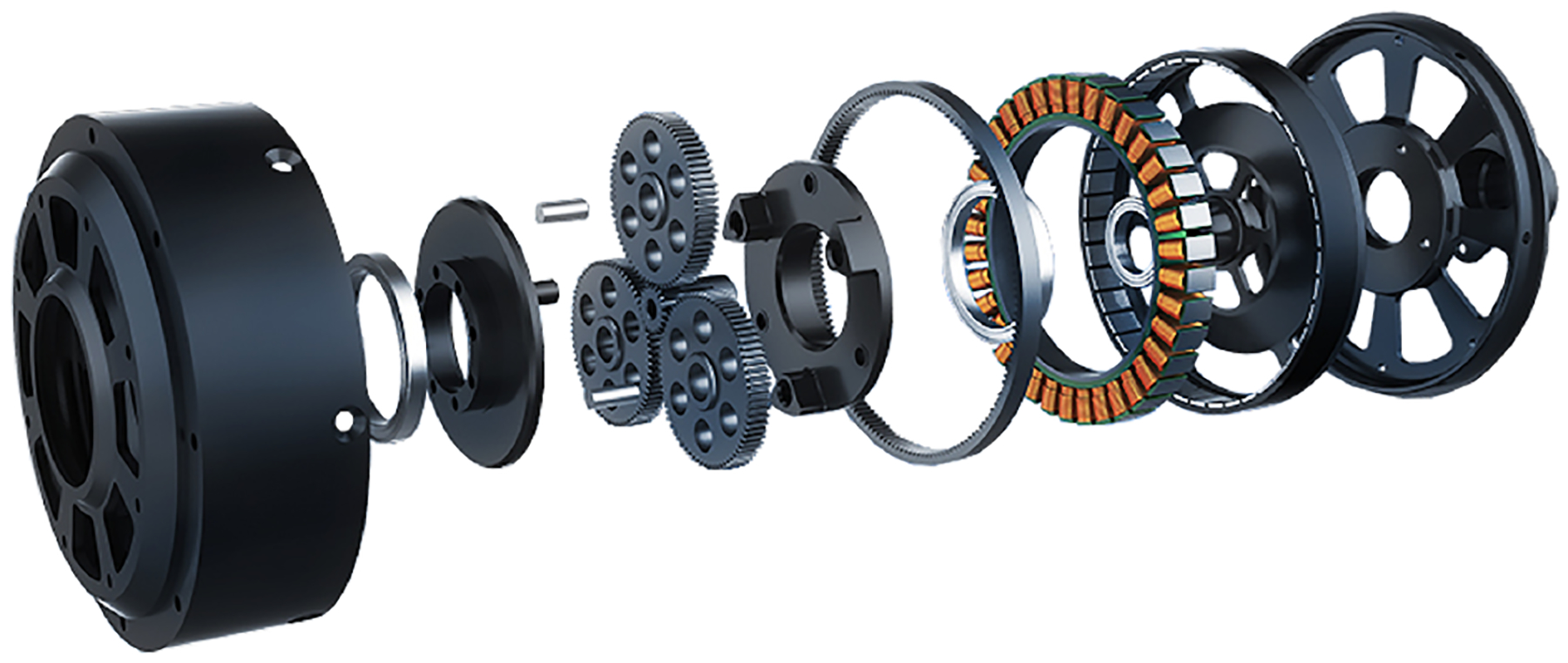
Exploded view of an open-frame version of T-motor AK80–9 [31].
B. Modular Design
To facilitate modularity and clinical viability, commercially-available orthoses were used as the basis of the mechanical human-robot interface. We combined robotic joints and custom uprights with the industrially designed human attachment interfaces, adjustment features, and straps of the T Scope Premier Post-Op Knee Brace (0.75 kg, see Fig. 3.b) and T Scope Post-Op Hip Brace (0.75 kg, see Fig. 3.a) (Breg, California, USA). The adjustability of Breg’s T-Scope braces, along with the fact that they have aluminum uprights and are sold in a variety of sizes, made them suitable for a wide range of user heights, weights, and ages. The two braces share a similar structure in which lateral metal uprights hinge near the anatomical joint axis, and interfacing pads are attached to these uprights with rivets or custom molded plastic features. The knee brace has a second set of uprights on the medial side of the leg. This structure allows for straightforward integration of custom robotic add-ons, and it facilitates rapid adjustment, donning, and doffing of M-BLUE.
Fig. 3.
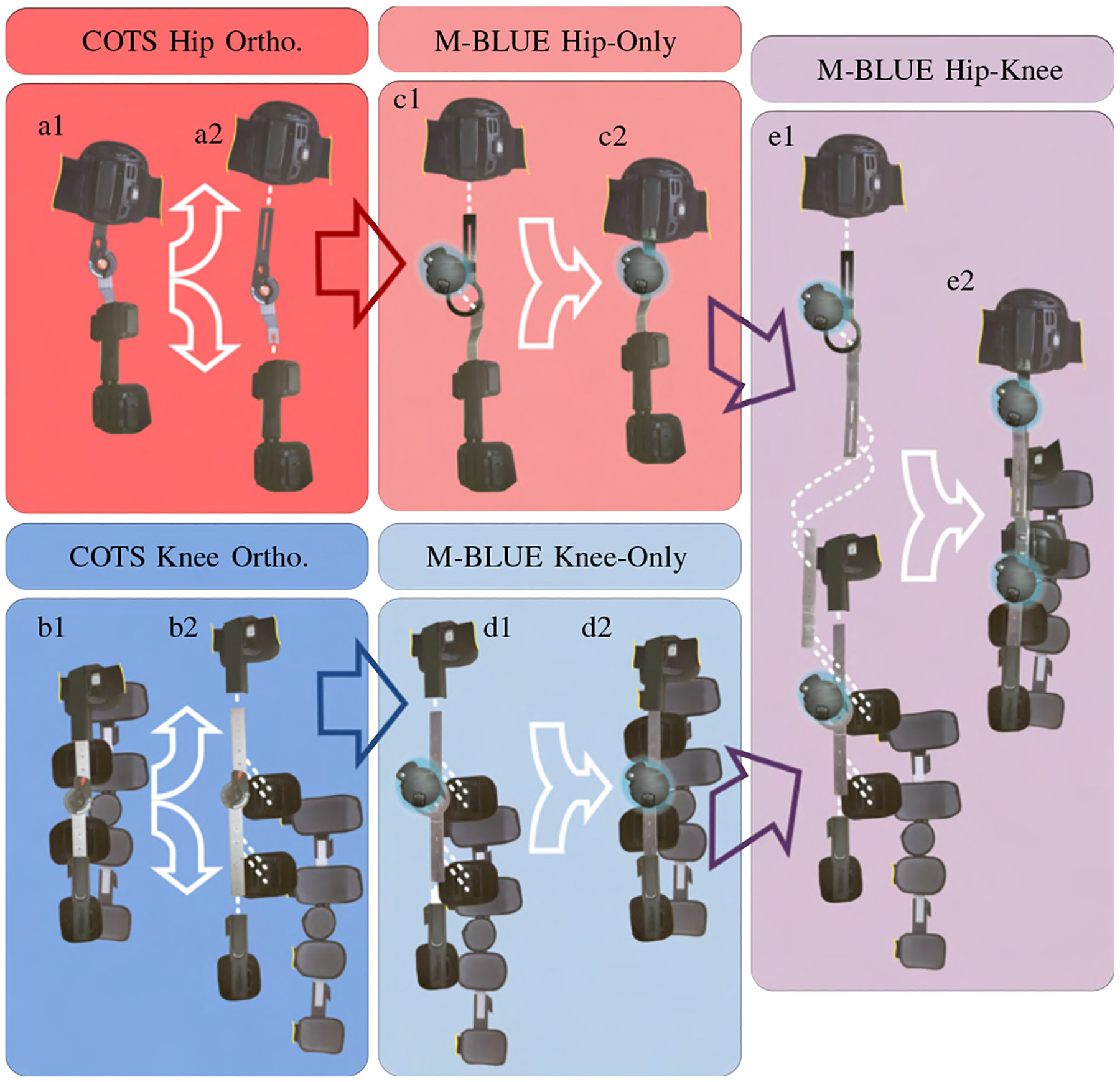
Modular Backdrivable Lower-limb Unloading Exoskeleton (M-BLUE): a1-2) Commercial off-the-shelf (COTS) T-Scope Hip brace disassembly, b1-2) COTS T-Scope Knee brace disassembly, c1-2) M-BLUE hip-only assembly, d1-2) M-BLUE knee-only assembly, and e1-2) M-BLUE hip-knee assembly.
The disassembled pieces of the T-Scope braces can be reassembled with the original uprights replaced by a custom set of sheet metal adaptors (Fig. 4). These adaptors are fabricated from 1/8” sheet aluminum (7075-T6, chosen for its high strength-to-weight ratio) primarily using a CNC router and a sheet metal brake for bending. While the tools needed to manufacture these sheet metal parts are not typically found in a clinical setting, they are easy to manufacture in commercial shops and could be distributed in kits similar to the way many of the metal components in traditional custom orthoses can be ordered from a catalog. We convert the orthoses by first harvesting the pads connected to the lateral uprights (Fig. 3.a,b), removing the original rivets using readily available tools (e.g., drill press, circular punch, Dremel, chisel). Four metal upright components (two from the knee brace, two from the hip brace) are then replaced by the analogous custom parts that interface with the input and output structures of the actuators (see Fig. 3). We retain the original medial uprights from the knee brace for use in the knee-only and hip-knee configuration (Fig. 3.d,e). The actuators are fastened to the sheet metal parts using bolts and pins. The riveted connections between pads and uprights are replaced by threaded fasteners, washers, and nuts to facilitate disassembly and reconfiguration. The adjustable length connection between the hip and knee structures in the hip-knee configuration (Fig. 3.e) is achieved with threaded fasteners. A supplemental video of the assembly process is available online [37].
Fig. 4.
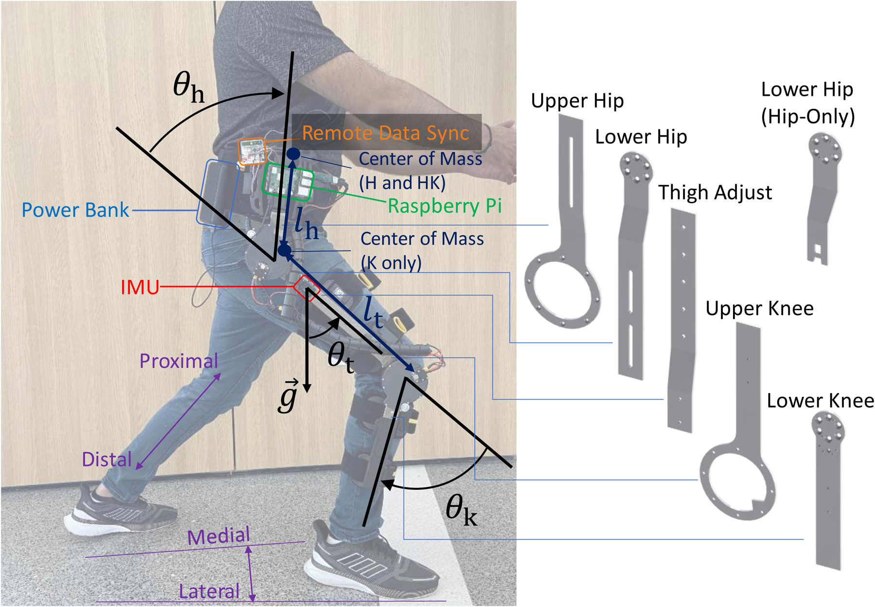
Left: M-BLUE hip-knee configuration with superimposed joint angle conventions for hip (θh) and knee (θk) angles, provided by actuator encoders, as well as thigh angle (θt) with respect to gravity (g), provided by the IMU (red). Thigh (lt) and hip (lh) length parameters, and center of mass for different configurations are shown in dark blue. Other annotated systems include the Raspberry Pi (green), its power source (blue), and a remote data sync board (orange; only required during EMG experiments). A convention for directional vocabulary (purple) is also included for reference. Right: CAD models of the custom sheet metal components used in various configurations.
The adaptor kit is designed to allow three powered orthosis configurations (Fig. 1). Changing configurations is an easily-performed process that takes several minutes. Future iterations could incorporate coupling mechanisms that enable quick release and attachment. The knee-only configuration (Fig. 3.d) utilizes a subset of the sheet metal components from the hip-knee configuration (Fig. 3.e) along with their affiliated fasteners (nuts, bolts, pins, and washers). The hip-only configuration (Fig. 3.c) uses a different set of distal components from the hip-knee configuration (distal components from the hip brace in Fig. 3.a rather than proximal components from the knee brace in Fig. 3.b). The distal upright for the hip joint has two configurations: one for connecting with a knee brace (Fig. 3.e), and one for independent hip use (Fig. 3.c). The knee-brace configuration allows for length adjustment of a thigh upright that attaches to the proximal knee upright (maintaining the pad configuration and adjustment mechanism of the proximal knee brace), while the hip-only configuration retains the original hip pad and adjustment mechanism of the distal hip brace. We weighed each configuration of the modified devices (including the utilized brace components, custom components, fasteners, and actuators with Dephy electronics, but not cables, batteries, and Raspberry Pi) and recorded their masses (hip only: 1.4 kg, knee only: 1.6 kg, hip-knee: 2.8 kg) for comparison to the stock braces. Hip ab/adduction is limited to the movement allowed by compliance in the user’s soft tissue, the orthosis uprights, and the human interface, as the Breg T-Scope Hip brace does not include a mechanism for this degree of freedom. This was deemed sufficient for the lifting/lowering task performed in this study but will be revisited in future work.
C. Embedded System and Control
The AK80–9 actuators were combined with the FASTER motor driver system by Dephy, Inc. (Maynard, MA), for a total actuator weight of 584 g. Based on [38], [39], the FASTER driver system features a high-bandwidth current control mode (corresponding to torque) and communicates via USB to a central Raspberry Pi 3B+ embedded computer (Raspberry Pi Foundation, Cambridge, United Kingdom) in a 300 Hz loop. The associated software application programming interface allows us to control the actuator in Python. The electrical system uses two lithium polymer batteries (Venom FLY 3600, 30C/22.2 V, Idaho, USA) mounted in a hip-bag (Fig. 4).
The controller has access to absolute motor encoders on the actuator models, as well as an inertial measurement system (3DM-GX5–25, LORD Microstrain, Vermont, USA) that provides a global rotation matrix for the orientation of the thigh segment of the orthosis. Using the assumption that the z-axis of the IMU is perpendicular to the sagittal plane, we convert this rotation matrix to a global sagittal-plane angle for the thigh, and—using the hip encoder—a measurement of the global angle of the waist belt/torso. Thus, we provide the controller with the hip angle θh, knee angle θk, and global thigh angle θt data as defined in Fig. 4.
To demonstrate the assistive capabilities of M-BLUE, we implemented a simple potential-energy shaping controller [26] based on a sagittal plane model of the human dynamics. This controller uses the M-BLUE actuators to offload the gravitational torques from a point mass which represents a fixed percentage α of the wearer’s recorded weight m. This controller is based on a modular, stance-only, 1- or 2-link kinematic chain model (depending on the M-BLUE configuration) starting from the most distal link connected to an actuator and working up. This means that for configurations with a powered knee, the shank is considered the base link, whereas the thigh is the base link in the hip-only configuration. The point mass is located in the most proximal link connected to an actuator: in the torso link for the hip and hip-knee configuration and in the thigh link for the knee-only configuration.
The control laws for the different configurations result directly from trigonometry. For example, the control law in the hip-knee configuration is
| (1) |
| (2) |
where g = 9.81 m/s2 represents gravitational acceleration, lt represents the length of the thigh link, and lh represents the height of the torso-fixed point mass above the hip center. We use the standing position to calibrate zero angles for all of θh, θk, and θt, so we can guarantee zero torques in the standing configuration. The locations for the offloaded point mass were tuned by hand to assist during squat lifting: lh = 177.8 mm into the torso for configurations with a hip joint, or at the hip center for the knee-only configuration (implemented as lh = 0, θh = 0). The thigh length was set to a default value of lt = 457.2 mm, but can be easily adjusted. Due to the nature of the control law, the controller is robust to discrepancies between the lt input magnitude and anatomical value; it can be seen as a slight modification of the assistance ratio α. The actuator torques were saturated at 25 Nm in extension, and at 0 Nm in flexion. This was done for safety and subject comfort, as the task performed did not require knee or hip flexion.
III. Benchtop Actuator Testing
We characterized the AK80–9 actuator’s static and dynamic backdrive torques to demonstrate the mechanical impedance of the system when it is not actively providing assistance, as well as the actuator’s friction to inform our open-loop current control model. Friction was characterized using a custom benchtop dynamometer setup (Fig. 5) which includes a rotary load cell, misalignment couplings, and an antagonist actuator. The antagonist actuator comprised a T-Motor U8 with a 50:1 transmission (Boston Gear, Charlotte, North Carolina), also driven using a Dephy FASTER motor driver system. Data were recorded from the actuators and the single-axis torque sensor (TRS605, FUTEK, Irvine, California; 16-bit ADS1115 ADC) using a Raspberry Pi 3B+ embedded computer.
Fig. 5.
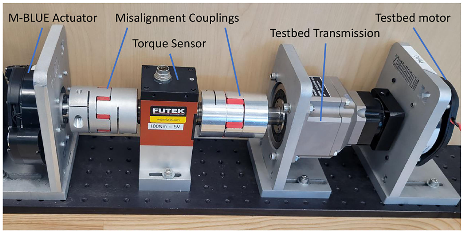
The benchtop platform used to evaluate the AK80–9 actuator [31].
A. Backdrive Tests
The static backdrive torque was quantified through manual deflection of the actuator output shaft via analog torque wrench (03727A, Neiko USA, China) from a stationary state until friction was overcome and the output shaft rotated. The static backdrive torque was measured under 0.5 Nm.
The dynamic backdrive torque was investigated by manually deflecting the AK80–9 from the misalignment coupling attached to the opposite side of the load cell (disconnected from the antagonist actuator) at a frequency and amplitude akin to those seen in the knee joint during able-bodied ambulation [35]. We selected target trajectories of 1 and 2 Hz with a peak-to-peak amplitude of 70 deg (Fig. 6) to approximate the behavior of the knee joint during walking. A 120 beats/min metronome and positional markings on the testbed governed the manual perturbations made for this test. Each frequency target (1 or 2 Hz) was tested for roughly 10 seconds.
Fig. 6.

Torque and position measurements from dynamic backdrive test.
The dynamic backdrive torque in this frequency range and amplitude setting was less than 2 Nm (Fig. 6). The backdrive torque magnitude increased from the 1 Hz to the 2 Hz target, consistent with an inertial component of backdrive torque [7].
B. Constant Torque and Speed Tests
The actuator was characterized with a non-linear grid of speed and torque values. Speeds included 0, 1, 3, 10, 30, 100, and 300 deg/s, and torques included 0, 1, 3, 5, 9, and 25 Nm. We iterated through all possible combinations of positive and negative speeds and torques (Fig. 7.a). In all cases, the antagonist actuator controlled speed while the primary actuator controlled current based on the nominal model τ ≊ grKti, where gr = 9 is the gear ratio, Kt = 0.14 is the q-axis torque constant [34], and i is the q-axis motor current. A brief 30 Nm step test confirmed the maximum torque (Fig. 7.b).
Fig. 7.
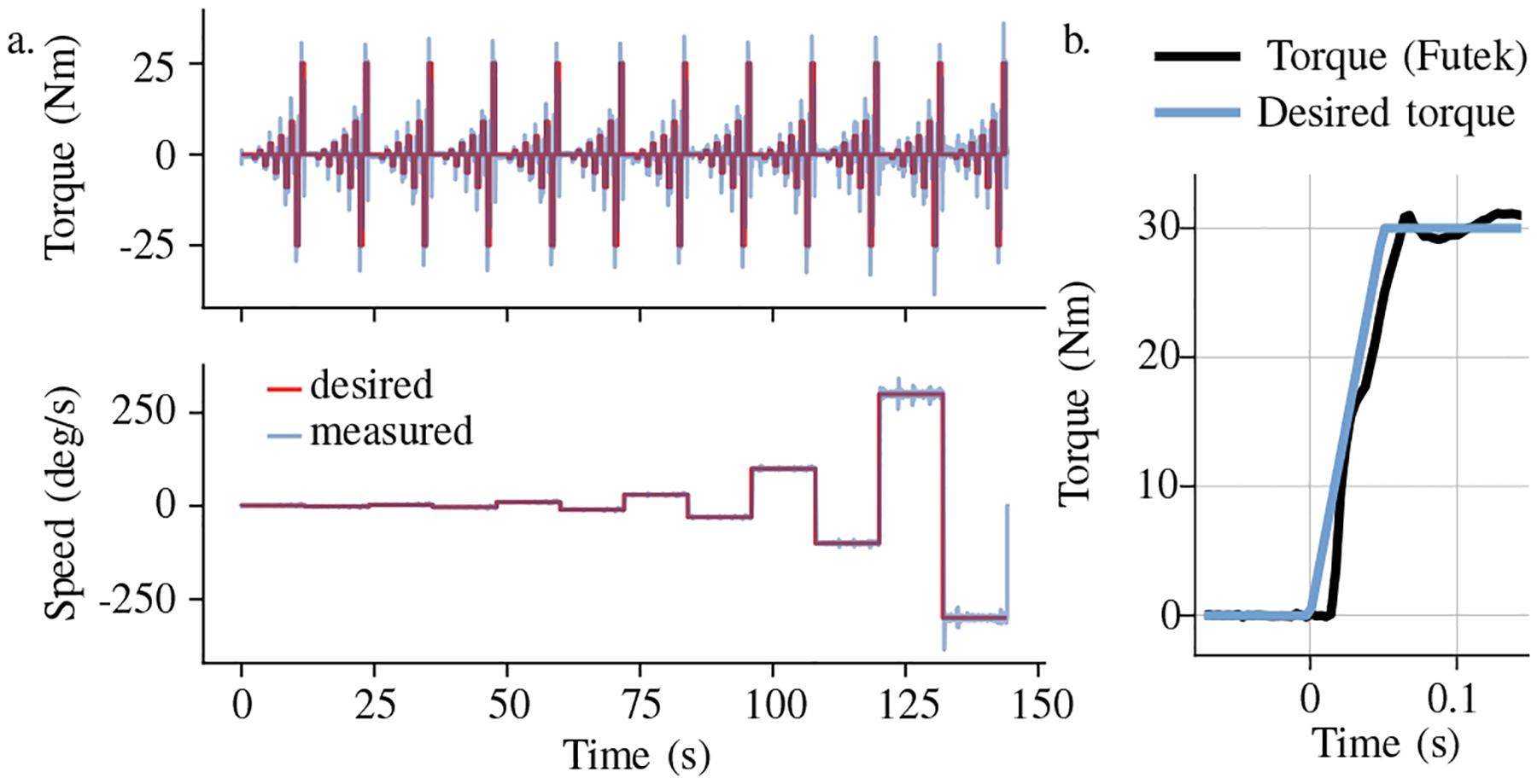
Constant torque and speed test (a), and 30 Nm step test (b).
C. System Identification
We used a least squares regression to predict the torque sensor values resulting from the constant torque and speed test. We chose to fit a model of the measured output torque
| (3) |
with b a torque sensor bias, kτ the nominal torque constant, kn a nonlinear current to torque relationship parameter, fC a Coulomb friction term, fg a gear friction term, and Iq the q-axis current. This model incorporates known friction phenomena and a term for non-linearity of the torque-current relationship, as we suspected magnetic saturation near the upper limit of the motor’s operating range. We filtered both the regressor matrix and the target torque with a second order low pass filter (2 Hz, ζ = 0.7). This 2 Hz frequency was chosen to focus the model on accurately predicting steady-state torque rather than the torque and current transients.
We found a model with 95% of errors less than 0.39 Nm. This model’s nonlinear torque constant kτ + kn∥Iq∥ varied linearly between 0.147 Nm/A near zero current to 0.125 Nm/A at 20 Amps (q-axis). Coulomb and gear friction were modeled at 0.37 Nm and 8.8% of the nominal torque, respectively. The existence of a gear friction component implies that backdriving resistance at high torque values will be larger than the backdriving resistance we measured in the static backdriving test, which was a zero-torque test.
D. Identifying Inertia
The constant torque and speed test is not well conditioned to estimate the reflected inertia, but the dynamic backdrive test shows the influence of reflected inertia. We performed a second regression on the first model’s residual when applied to predicting the result of this backdrive test. The filter from the previous identification was re-used.
The second model included only a bias and a reflected inertia term. The second model regression reduced the torque prediction RMSE in the dynamic backdrive trial from 0.28 Nm to 0.061 Nm. For reference, the filtered torque signal from this trial had a RMSE of 0.36 Nm relative to zero-torque, demonstrating the effect of inertia which the first model fails to describe. The reflected inertia estimate was 92.11 kg·cm2, less than half of the reflected inertia of our previous knee exoskeleton actuator (200.9 kg · cm2) [7].
IV. Human Subject Experiment
A. Methods
A single able-bodied human subject (male, 34 years old, 82 kg, 178 cm tall) was recruited for the lifting/lowering case study. The experimental protocol was approved by the Institutional Review Board of the University of Michigan (HUM00164931). After appropriate skin preparation, we taped six electromyography (EMG) electrodes (Trigno Avanti, Delsys, Massachusetts, USA) onto the subject’s right lower limb over the vastus medials oblique (VM), vastus lateralis (VL), rectus femoris (RF), biceps femoris (BF), semitendinosus (ST), and gluteus maximus (GM) to assess muscle activation. A maximum voluntary contraction (MVC) procedure which consisted of explosive squats (dynamic contraction) as well as maximal isometric contraction against manual resistance was completed and used to normalize EMG data to %MVC.
The lifting/lowering experiment was performed over floor-embedded force plates (AMTI, Massachusetts, USA). The subject stood with each foot on a separate force plate, and was provided visual feedback of the vertical ground reaction forces. Visual feedback was provided to ensure the subject retained symmetrical loading of their legs. We tested four experimental modes: bare mode (without exoskeleton), and hip-only, knee-only, and hip-knee exoskeleton configurations (see Fig. 1). The modular exoskeleton counteracted approximately 20% of the gravitational torques on the supported joints (hip and/or knee). For each configuration, the subject performed 20 alternating lifting and lowering (L&L) squats using a 12.5 kg mass—approximately 15% of the subject’s body mass. The sequence of the trials was bare, knee only, hip only, then hip-knee. All trials were performed on the same day. A 60 beats/min metronome was used to guide the subject’s squatting pace in all trials. The L&L sequence started with the subject standing upright on the first beat. On the second beat, the subject achieved a squat position and either grasped or released the weight for a lifting or lowering trial, respectively. The sequence ended with the subject returning to an upright standing posture on the third beat. Approximately 2–3 seconds (2–3 beats) of rest was taken after the third beat. About 10–15 minutes of rest was provided between configurations. A supplemental video of the experiment is available for download.
We cropped L&L trials into individual repetitions using the thigh angle (acquired from additional sensors in the RF EMG sensor). Each muscle’s EMG was demeaned, bandpass filtered (20 – 200 Hz), and smoothed with a moving 100 ms window RMS filter. After normalizing the EMG to %MVC, we calculated the integral with respect to time to represent muscular effort as %MVC·s for each repetition. Further, the peak muscle activation during each repetition was found.
B. Results
The M-BLUE system delivered meaningful assistance to the knee and/or hip during the L&L task, enabling considerable reductions in activation of the squat musculature. Extension torques up to 26 Nm and 15 Nm were delivered to the knee and hip joints, respectively (see Fig. 8). The ensemble average EMG plots (Fig. 9) show that the assistance torques were generally synchronous with the knee and hip extensor muscle activations, especially during the concentric part of the motion (50–100% L&L cycle). Muscle activation was generally quite low during the eccentric part of the motion (0–50% L&L cycle) for all modes. Importantly, muscle activations (barring the BF) in the concentric portion were substantially lower for all exoskeleton configurations compared to bare mode. Major reductions in muscle activations were apparent with configurations that included the knee module. Addition of the hip module to the knee module did not result in further EMG reductions. Yet, the hip-only configuration facilitated meaningful EMG reductions compared to bare. Ultimately, the summary metrics (muscle effort and peak activation) in Tabs. I-II show M-BLUE was beneficial in all three exoskeleton configurations. With the exception of the BF, the mean effort and mean peak EMG of all muscles tested were substantially lower with exoskeleton assistance than without it. In contrast, the BF activations were quite similar for all modes, with the standard deviations overlapping throughout the L&L cycle.
Fig. 8.
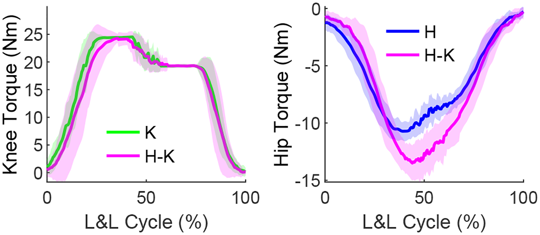
Knee (left) and hip (right) torques for knee-only (K), hip-only (H), and hip-knee (H-K) exoskeleton configurations during L&L tasks.
Fig. 9.
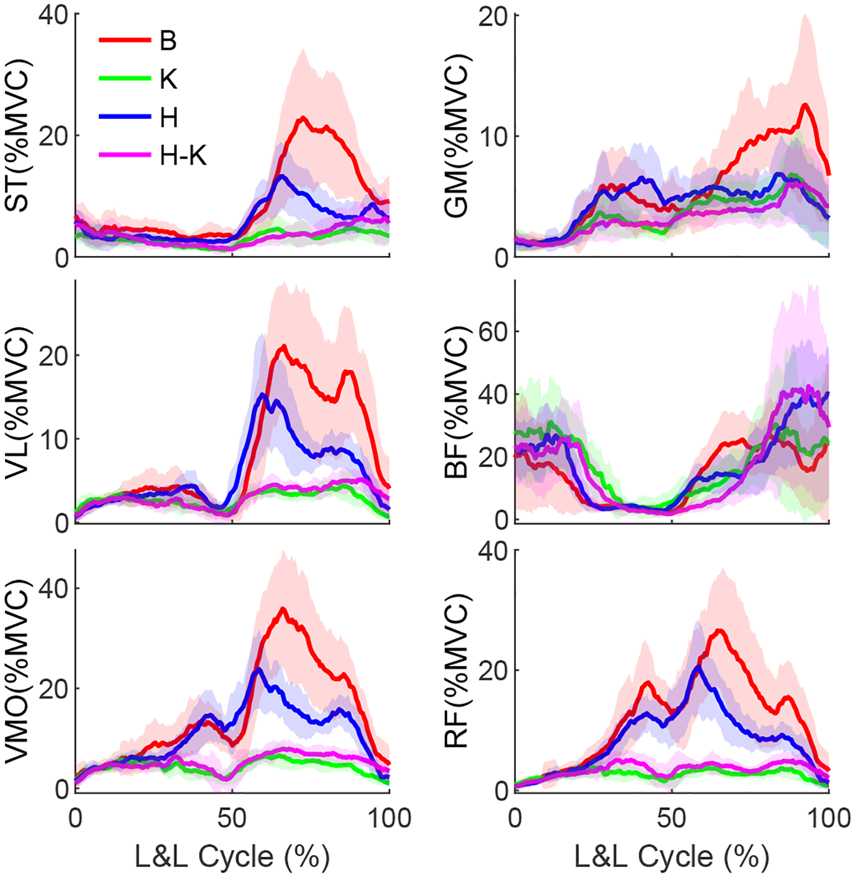
Ensemble average muscle activation profiles for bare (B) vs. exoskeleton configurations: knee-only (K), hip-only (H), and hip-knee (HK) exoskeleton configurations during L&L task.
V. Discussion
The presented design and performance characteristics of M-BLUE demonstrate its potential impact for clinical applications. The benchtop and human subject experiments indicate this design paradigm is appropriate for assisting the musculature of individuals with mild to moderate impairments. These aspects of the study are discussed below, and serve to motivate future work with M-BLUE.
1). Hardware Performance:
The molded plastic and sheet metal structure (both the stock components and the custom revisions) adequately transferred the applied loads, and may be able to withstand even higher output torques. Future experimentation will confirm whether the current design paradigm is sufficient for the upper limit of the actuators’ torque capabilities (30 Nm). The rapid don/doff time and ease of adjustment provided by the commercial orthotic interface will facilitate productive research sessions, particularly in instances where the wearer’s available time is a limiting factor. Further design refinements may improve the physical system through the introduction of mechanisms to prevent distal sliding of the knee brace, and to allow passive ab/adduction of the hip joint to occur more freely. Considerations will also be made for interfacing M-BLUE with the commercial Dephy ExoBoot [10], [33] in cases where plantarflexion assistance is merited.
2). Benchtop Analysis:
The benchtop assessment of the M-BLUE actuators indicated that these actuators are well-suited to the application of partial-assist, lower-limb exoskeletons in terms of cost, comfort, and ease of control. The low backdrive torque exhibited during zero current control, even during highly dynamic perturbations, suggests that M-BLUE will be capable of assisting users across a variety of tasks (overground walking, stairs, etc.), not only those which occur on a more gradual timescale (such as L&L). The precision with which the derived torque output model predicts the actuator’s behavior across torques and speeds indicates that M-BLUE is capable of executing open-loop control reliably. This has significant implications on cost and weight, as it eliminates the need for additional sensor hardware to close the feedback loop and achieve high-performance control.
3). Preliminary Human Subject Results:
The single human subject experiment yielded promising results, with the majority of the investigated muscles showing a clear reduction of both peak muscle activation and effort, particularly in configurations that include the knee module. The knee actuator alone produced substantial EMG reduction, with prominent decreases visible in most of the muscles’ activation profiles, while the addition of the hip actuator did not substantively improve performance. This can likely be attributed to the greater knee joint deflection required to perform a squat lift (relative to the hip joint). The results of this preliminary study suggest that the knee-only configuration may have the greatest potential for reducing fatigue in repetitive squat lifting tasks, although a higher assistance ratio for the hip controller may improve the hip module’s efficacy by increasing the torque output. It is also possible that the hip module would have a greater effect on EMG during activities that demand more work at the hips, such as a stoop lift [40]. Recent industrial exoskeletons actuate the hip for this purpose [41], [42], whereas actuating distal joints like the knee may promote the safer squat lifting technique.
4). Future Clinical Studies:
This modular orthotic technology has the potential for clinical impact in several populations with mild to moderate joint-specific impairments. First, the L&L case study suggests the presented system can reduce muscular fatigue leading to risky lifting posture [32]. Assisting the quadriceps in particular may encourage and prolong the use of the recommended squat technique in workplace L&L tasks known to cause low back pain [40]. Thus, bilateral configurations of M-BLUE could serve to prevent chronic overuse musculoskeletal injuries in the workplace, which cost employers billions every year [43]. Second, M-BLUE could provide a novel non-surgical treatment for osteoarthritic pain associated with compressive loads at the hip or knee. We previously found that lightweight exoskeletons without a load-bearing parallel joint structure (as in military exoskeletons) are well suited for reducing compressive joint loads due to muscle contraction [44]. Conventional OA braces unload the medial or lateral compartments of the knee but cannot unload the patellofemoral compartment, which can only be done by reducing quadriceps muscle force. Our modified hip orthosis could provide a new orthotic treatment for hip OA, which is more difficult to unload than the knee. By reducing peak muscle activation/force, patients may be able to perform demanding tasks such as sit-stand and stair climbing with less pain, encouraging a more active lifestyle to control the progression of OA. Third, targeting stroke deficits may reduce compensations at more functional joints, reducing the associated cognitive burden, energy expenditure, fall risk, and joint overuse [45]. This motivates applications in mobile gait training to increase flexibility in the clinic and dosage via community-based therapy. Fourth, bilateral hip and knee orthoses could improve mobility and quality of life for individuals with age-related immobility [2]. Some of these populations would further benefit from integration of the Dephy ExoBoot [10], [33] as an ankle module for plantarflexion assistance. These investigations are left to future work.
VI. Conclusion
This paper introduced the design and validation of a modular exoskeleton system (M-BLUE) that leverages highly backdrivable, torque-dense actuators and commercial orthoses. The benchtop tests verified the low mechanical impedance of the actuator and the accuracy of open-loop current control as a means to achieve desired torques via a regression-based model. The human subject experiment confirmed the compatibility of our modular exoskeleton system with an able-bodied wearer, and demonstrated the efficacy of the device at substantially reducing muscle activation during a demanding L&L task.
Future work will include the extension of the modular design to encompass bilateral configurations including a powered ankle joint, as well as implementation of more advanced task-invariant controllers [25], [26]. Future human subject experiments will investigate the performance of these configurations and controllers on larger populations of able-bodied subjects, along with pathological populations such as osteoarthritis and age-related frailty. We will also compile and disseminate instructive guides on the disassembly of stock brace configurations and installation of M-BLUE hardware to assist clinicians in the implementation of modular exoskeletons.
Supplementary Material
TABLE I.
Mean muscular effort (± SD) comparisons.
| Bare | Knee | Hip | Hip-Knee | |
|---|---|---|---|---|
| VM | 33.2 (6.6) | 10.5 (0.9) | 27.7 (2.9) | 13.4 (2.2) |
| RF | 26.2 (3.8) | 6.5 (0.9) | 21.2 (2.6) | 9.0 (1.8) |
| VL | 18.0 (3.9) | 6.7 (0.6) | 14.7 (1.9) | 7.9 (0.8) |
| BF | 31.5 (6.4) | 41.8 (7.0) | 42.1 (7.2) | 42.9 (11.3) |
| ST | 19.9 (3.4) | 7.4 (0.9) | 14.3 (2.1) | 8.8 (1.5) |
| GM | 12.6 (1.8) | 8.5 (1.3) | 11.4 (1.0) | 8.2 (1.2) |
TABLE II.
Mean peak activation (± SD) comparisons.
| Bare | Knee | Hip | Hip-Knee | |
|---|---|---|---|---|
| VM | 44.1 (10.8) | 9.3 (1.5) | 29.4 (6.6) | 10.4 (1.9) |
| RF | 33.8 (8.3) | 6.1 (1.3) | 24.4 (6.4) | 7.4 (2.1) |
| VL | 29.3 (8.2) | 6.0 (1.1) | 19.8 (6.9) | 6.8 (1.2) |
| BF | 50.4 (14.1) | 58.1 (11.6) | 53.6 (13.0) | 66.5 (23.9) |
| ST | 29.6 (9.7) | 7.7 (1.9) | 16.0 (5.1) | 10.5 (3.4) |
| GM | 17.0 (5.6) | 9.1 (3.2) | 11.7 (2.8) | 8.5 (2.9) |
ACKNOWLEDGMENT
The authors thank Ross Cortino for his early assistance and Vamsi Peddinti for experiment support.
This paper was recommended for publication by Editor Pietro Valdastri upon evaluation of the Associate Editor and Reviewers’ comments. This work was supported by the National Science Foundation under Award Numbers 1949869 and 1953908, and by the National Institute of Biomedical Imaging and Bioengineering of the NIH under Award Number R01EB031166. The content is solely the responsibility of the authors and does not necessarily represent the official views of the NSF or NIH.
References
- [1].“Prevalence of Disability and Disability Type among Adults, United States,” 2013. [Online]. Available: https://www.cdc.gov/ncbddd/disabilityandhealth/features/key-findings-community-prevalence.html [DOI] [PMC free article] [PubMed] [Google Scholar]
- [2].Grimmer M, Riener R, Walsh CJ, and Seyfarth A, “Mobility related physical and functional losses due to aging and disease-a motivation for lower limb exoskeletons,” J. Neuroeng. Rehabilitation, vol. 16, no. 1, p. 2, 2019. [DOI] [PMC free article] [PubMed] [Google Scholar]
- [3].Baunsgaard CB, Nissen UV, Brust AK, Frotzler A, Ribeill C, Kalke Y-B, León N, Gómez B, Samuelsson K, Antepohl W, and et al. , “Gait training after spinal cord injury: safety, feasibility and gait function following 8 weeks of training with the exoskeletons from Ekso Bionics,” Spinal cord, vol. 56, no. 2, p. 106, 2018. [DOI] [PubMed] [Google Scholar]
- [4].Farris RJ, Quintero HA, and Goldfarb M, “Preliminary evaluation of a powered lower limb orthosis to aid walking in paraplegic individuals,” IEEE Trans. Neural Syst. Rehabilitation Eng, vol. 19, no. 6, pp. 652–659, 2011. [DOI] [PMC free article] [PubMed] [Google Scholar]
- [5].Zeilig G, Weingarden H, Zwecker M, Dudkiewicz I, Bloch A, and Esquenazi A, “Safety and tolerance of the ReWalk™ exoskeleton suit for ambulation by people with complete spinal cord injury: a pilot study,” J. spinal cord medicine, vol. 35, no. 2, pp. 96–101, 2012. [DOI] [PMC free article] [PubMed] [Google Scholar]
- [6].Murray S, Ha K, Hartigan C, and Goldfarb M, “An assistive control approach for a lower-limb exoskeleton to facilitate recovery of walking following stroke,” IEEE Trans. Neural Syst. Rehabilitation Eng, vol. 23, no. 3, pp. 441–449, 2015. [DOI] [PubMed] [Google Scholar]
- [7].Zhu H, Nesler C, Divekar N, Peddinti V, and Gregg R, “Design Principles for Compact, Backdrivable Actuation in Partial-Assist Powered Knee Orthoses,” IEEE/ASME Trans. Mechatron, 2021. [DOI] [PMC free article] [PubMed] [Google Scholar]
- [8].Seok S, Wang A, Chuah MYM, Hyun DJ, Lee J, Otten DM, Lang JH, and Kim S, “Design principles for energy-efficient legged locomotion and implementation on the MIT cheetah robot,” IEEE/ASME Trans. Mechatronics, vol. 20, no. 3, pp. 1117–1129, 2014. [Google Scholar]
- [9].Tucker MR, Olivier J, Pagel A, Bleuler H, Bouri M, Lambercy O, del Millan J, Riener R, Vallery H, and Gassert R, “Control strategies for active lower extremity prosthetics and orthotics: a review,” Neuro-Engineering and Rehabilitation, vol. 12, no. 1, 2015. [DOI] [PMC free article] [PubMed] [Google Scholar]
- [10].Mooney LM, Rouse EJ, and Herr HM, “Autonomous exoskeleton reduces metabolic cost of human walking,” J. Neuroeng. Rehabilitation, vol. 11, no. 1, 2014. [DOI] [PMC free article] [PubMed] [Google Scholar]
- [11].Lv G, Zhu H, and Gregg R, “On the design and control of highly backdrivable lower-limb exoskeletons,” IEEE Control Systems Magazine, vol. 38, no. 6, pp. 88–113, 2018. [DOI] [PMC free article] [PubMed] [Google Scholar]
- [12].Wang J, Li X, Huang TH, Yu S, Li Y, Chen T, Carriero A, Oh-Park M, and Su H, “Comfort-Centered Design of a Lightweight and Backdrivable Knee Exoskeleton,” IEEE Robotics and Automation Letters, vol. 3, no. 4, pp. 4265–4272, 2018. [Google Scholar]
- [13].Yu S, Huang T-H, Yang X, Jiao C, Yang J, Chen Y, Yi J, and Su H, “Quasi-direct drive actuation for a lightweight hip exoskeleton with high backdrivability and high bandwidth,” IEEE/ASME Trans. Mechatronics, vol. 25, no. 4, pp. 1794–1802, 2020. [DOI] [PMC free article] [PubMed] [Google Scholar]
- [14].Lee D, Kwak EC, McLain BJ, Kang I, and Young AJ, “Effects of assistance during early stance phase using a robotic knee orthosis on energetics, muscle activity, and joint mechanics during incline and decline walking,” IEEE Trans. Neural Syst. Rehabilitation Eng, vol. 28, no. 4, pp. 914–923, 2020. [DOI] [PubMed] [Google Scholar]
- [15].Rahim AA, Che-Ani A, Hussain Z, Boudville R, and Ahmad KA, “Development of powered knee orthosis for fes-assisted knee swing,” in IEEE Int. Conf. Control System, Computing Eng., 2019, pp. 209–214. [Google Scholar]
- [16].Asbeck AT, Schmidt K, Galiana I, Wagner D, and Walsh CJ, “Multi-joint soft exosuit for gait assistance,” in IEEE Int. Conf. Robotics and Automation. IEEE, 2015, pp. 6197–6204. [Google Scholar]
- [17].Awad LN, Bae J, O’Donnell K, De Rossi SMM, Hendron K, Sloot LH, Kudzia P, Allen S, Holt KG, Ellis TD, and Walsh CJ, “A soft robotic exosuit improves walking in patients after stroke,” Science translational medicine, vol. 9, no. 400, p. eaai9084, 2017. [DOI] [PubMed] [Google Scholar]
- [18].Yu S, Huang T-H, Wang D, Lynn B, Sayd D, Silivanov V, Park YS, Tian Y, and Su H, “Design and Control of a High-Torque and Highly Backdrivable Hybrid Soft Exoskeleton for Knee Injury Prevention During Squatting,” IEEE Robotics and Automation Letters, vol. 4, no. 4, pp. 4579–4586, 2019. [Google Scholar]
- [19].Shepherd MK and Rouse EJ, “Design and validation of a torque-controllable knee exoskeleton for sit-to-stand assistance,” IEEE/ASME Trans. Mechatronics, vol. 22, no. 4, pp. 1695–1704, 2017. [Google Scholar]
- [20].MacLean MK and Ferris DP, “Energetics of walking with a robotic knee exoskeleton,” J. Appl. Biomech, vol. 35, no. 5, pp. 320–326, 2019. [DOI] [PubMed] [Google Scholar]
- [21].Kusuda Y, “In quest of mobility–Honda to develop walking assist devices,” Industrial Robot: An Int. Journal, 2009. [Google Scholar]
- [22].Lee S-H, Lee H-J, Chang WH, Choi B-O, Lee J, Kim J, Ryu G-H, and Kim Y-H, “Gait performance and foot pressure distribution during wearable robot-assisted gait in elderly adults,” J. Neuroeng. Rehabilitation, vol. 14, no. 1, p. 123, 2017. [DOI] [PMC free article] [PubMed] [Google Scholar]
- [23].Kenneally G, De A, and Koditschek DE, “Design principles for a family of direct-drive legged robots,” IEEE Robotics and Automation Letters, vol. 1, no. 2, pp. 900–907, 2016. [Google Scholar]
- [24].Elery T, Rezazadeh S, Nesler C, and Gregg R, “Design and Validation of a Powered Knee-Ankle Prosthesis with High-Torque, Low-Impedance Actuators,” IEEE Trans Robotics, vol. 36, no. 6, pp. 1649–1668, 2020. [DOI] [PMC free article] [PubMed] [Google Scholar]
- [25].Lin J, Divekar N, Lv G, and Gregg R, “Optimal Task-Invariant Energetic Control for a Knee-Ankle Exoskeleton,” IEEE Control Systems Letters, vol. 5, no. 5, pp. 1711–1716, 2021. [Google Scholar]
- [26].Divekar NV, Lin J, Nesler C, and Gregg RD, “A Potential Energy Shaping Controller with Ground Reaction Force Feedback for a Multi-Activity Knee-Ankle Exoskeleton,” in IEEE Int. Conf. Biomed. Robot. Biomechatron., 2020, p. 8. [Google Scholar]
- [27].Brackx B, Geeroms J, Vantilt J, Grosu V, Junius K, Cuypers H, Vanderborght B, and Lefeber D, “Design of a modular add-on compliant actuator to convert an orthosis into an assistive exoskeleton,” in IEEE Int. Conf. Biomed. Robot. Biomechatron., 2014, pp. 485–490. [Google Scholar]
- [28].Hwang S, Kim Y, and Kim Y, “Lower extremity joint kinetics and lumbar curvature during squat and stoop lifting,” BMC Musculoskeletal Disorders, vol. 10, no. 1, p. 15, 2009. [DOI] [PMC free article] [PubMed] [Google Scholar]
- [29].Meijneke C, van Oort G, Sluiter V, van Asseldonk E, Tagliamonte N, Tamburella F, Pisotta I, Masciullo M, Arquilla M, Molinari M et al. , “Symbitron exoskeleton: Design, control, and evaluation of a modular exoskeleton for incomplete and complete spinal cord injured individuals,” IEEE Trans. Neural Syst. Rehabilitation Eng, vol. 29, pp. 330–339, 2021. [DOI] [PubMed] [Google Scholar]
- [30].Li Y, Guan X, Han X, Tang Z, Meng K, Shi Z, Penzlin B, Yang Y, Ren J, Yang Z et al. , “Design and preliminary validation of a lower limb exoskeleton with compact and modular actuation,” IEEE access, vol. 8, pp. 66 338–66 352, 2020. [Google Scholar]
- [31].“T-Motor AK80–9,” 2020. [Online]. Available: http://store-en.tmotor.com/goods.php?id=982
- [32].Trafimow JH, Schipplein OD, Novak GJ, and Andersson GB, “The effects of quadriceps fatigue on the technique of lifting.” Spine, vol. 18, no. 3, pp. 364–367, 1993. [DOI] [PubMed] [Google Scholar]
- [33].Ingraham KA, Remy CD, and Rouse EJ, “User preference of applied torque characteristics for bilateral powered ankle exoskeletons,” in IEEE Int. Conf. Biomed. Robot. Biomechatron., 2020. [Google Scholar]
- [34].Lee UH, Pan C-W, and Rouse EJ, “Empirical Characterization of a High-performance Exterior-rotor Type Brushless DC Motor and Drive,” in IEEE/RSJ Int. Conf. Intelligent Robots Systems, 2019, pp. 8018–8025. [Google Scholar]
- [35].Winter DA, Biomechanics and Motor Control of Human Movement, 2nd ed. New York, NY: Wiley, 2009. [Google Scholar]
- [36].Roy G, Nadeau S, Gravel D, Piotte F, Malouin F, and McFadyen BJ, “Side difference in the hip and knee joint moments during sit-to-stand and stand-to-sit tasks in individuals with hemiparesis,” Clinical biomechanics, vol. 22, no. 7, pp. 795–804, 2007. [DOI] [PubMed] [Google Scholar]
- [37].“Assembly and reconfiguration of the modular backdrivable lower-limb unloading exoskeleton (M-BLUE),” 2022. [Online]. Available: https://youtu.be/Q0HYkWj2wf8
- [38].Duval J-F and Herr HM, “FlexSEA: Flexible, Scalabe Electronics Architecture for Wearable Robotic Applications,” in IEEE Int. Conf. Biomed. Robot. Biomechatron., 2016, pp. 1236–1241. [Google Scholar]
- [39].——, “FlexSEA-Execute: Advanced Motion Controller for Wearable Robotic Applications,” in IEEE Int. Conf. Biomed. Robot. Biomechatron., 2016, pp. 1056–1061. [Google Scholar]
- [40].Hsiang SM, Brogmus GE, and Courtney TK, “Low back pain (LBP) and lifting technique–A review,” Int. J. Industrial Ergonomics, vol. 4, no. 19, pp. 59–74, 1997. [Google Scholar]
- [41].Huysamen K, de Looze M, Bosch T, Ortiz J, Toxiri S, and O’Sullivan L, “Assessment of an active industrial exoskeleton to aid dynamic lifting and lowering manual handling tasks,” Appl. Ergon, 2018. [DOI] [PubMed] [Google Scholar]
- [42].Wei W, Zha S, Xia Y, Gu J, and Lin X, “A hip active assisted exoskeleton that assists the semi-squat lifting,” Appl. Sci, 2020. [Google Scholar]
- [43].“Work-Related Musculoskeletal Disorders & Ergonomics,” 2016. [Online]. Available: https://www.cdc.gov/workplacehealthpromotion/health-strategies/musculoskeletal-disorders/
- [44].Medrano RL, Rouse EJ, and Thomas GC, “Biological joint loading and exoskeleton design,” IEEE Trans. Med. Robot. Bionics, vol. 3, no. 3, pp. 847–851, 2021. [Google Scholar]
- [45].Woolley SM, “Characteristics of gait in hemiplegia,” Topics in stroke rehabilitation, vol. 7, no. 4, pp. 1–18, 2001. [DOI] [PubMed] [Google Scholar]
Associated Data
This section collects any data citations, data availability statements, or supplementary materials included in this article.


