Abstract
MR 영상에서 금속 인공물은 금속 삽입물과 주변 조직의 magnetic susceptibility의 차이에 의해 나타난다. 금속 인공물을 줄이는 일반적인 방법은 낮은 자장의 MR 장비를 사용하고, 금속물의 방향에 따라 주파수부호화 방향과 위상부호화 방향을 바꾸고, receiver bandwidth와 matrix를 높이며, 절편 두께를 작게 하고 short tau inversion recovery나 Dixon 기법을 사용하여 fat-suppression을 하는 것이다. Slice-encoding for metal artifact correction이나 multi-acquisition variable-resonance image combination을 통해 보다 강력하게 금속 인공물을 줄일 수 있다. 그러나 이 방법의 최대 단점은 촬영 시간이 길다는 것이나 최근 개발된 compressed sensing과 같은 고속화 기법을 통해 이를 해결할 수 있게 되었다.
Keywords: Magnetic Resonance Imaging, Artifact, Metals, Prostheses and Implants
Abstract
Metallic artifacts on MR imaging are typically induced by differences in magnetic susceptibility between the metallic implant and surrounding tissue. Conventional techniques for metal artifact reduction require MR machines with low field strength, shift in the frequency-encoding and phase-encoding directions according to the axis of metallic implant, increased receiver bandwidth and matrix, decreased slice thickness, and utilization of the short tau inversion recovery or Dixon method for fat-suppression. Slice-encoding for metal artifact correction and multi-acquisition variable-resonance image combination can dramatically reduce the number of metallic artifacts. However, these sequences have a considerably long acquisition time. Furthermore, the recently developed acceleration techniques including compressed sensing can solve this problem.
서론
정형외과적 영역에서 금속 삽입물(metal implant)은 골절의 안정화나 관절 유합, 척추 고정술 등의 목적으로 사용하고 있다. 특히, 고령화에 따라 인공관절 수술의 빈도뿐만 아니라, 인공관절 수술 후 aseptic loosening, polyethylene wearing, metallosis, periprosthetic fracture와 같은 합병증 발생의 빈도도 증가하여 이로 인한 교정수술(revision surgery)의 빈도가 증가하고 있다(1,2). 단순 촬영이나 CT는 금속 삽입술 후 삽입된 금속물의 위치와 상태 그리고 금속물 주변의 뼈의 변화를 관찰하는 데 도움이 된다. 그러나, 단순 촬영이나 CT는 연부조직의 변화를 파악하는데 한계가 있다. MR 영상은 연조직 간의 대조도가 우수하고 단순 촬영이나 CT에서 보이지 않던 뼈의 변화를 관찰하는데 탁월하다. 그러나, 삽입된 금속물은 MR 영상에서 인공물을 발생 시켜 그 사용이 제한적이었다. 이에 일반적인 MR 영상에서 여러 가지 parameter를 조절하여 금속 인공물을 줄이기 위한 지속적인 노력이 있었고, 최근 금속 인공물을 줄이는 특별한 기술과 더불어 이를 가속화할 수 있는 기술들이 개발되었다. 여기에서는 MR 영상에서의 금속 인공물의 발생 원인 및 양상에 대해 살펴보고 금속 인공물을 감소시키기 위한 일반적인 방법과 특별한 기법에 대해 알아보고자 한다.
금속 인공물 발생 원인 및 형태
MR 영상에서 금속 인공물은 금속 삽입물과 주변 조직의 magnetic susceptibility의 차이에 의해 발생한다. Magnetic susceptibility란 물질이 주자장(B0)에 노출되었을 때 자성을 띄게 되는 성질로, parts per million (이하 ppm)으로 표현하고, 1.5 T에서 1 ppm은 대략 60 Hz에 해당한다(3). 우리 인체는 −10 ppm 정도의 약한 반자성(diamagnetic)의 성질을 가지고, 금속은 100~200 ppm 정도의 상자성(paramagnetic) 혹은 1000 ppm 혹은 그 이상의 강자성(ferromagnetic)의 성질을 가진다(4,5). 따라서 금속을 주자장에 놓으면 금속 주변으로 새로운 자장이 생기고, 새로이 생성된 자장은 주자장에 영향을 미쳐 주자장을 불균질하게 만들고 이로 인해 금속 주변 스핀(spin)들의 주파수(frequency)와 위상(phase)이 변하게 되어 금속 인공물이 발생한다. MR 영상에서 금속 인공물은 크게 네 가지의 형태 즉, dephasing의 가속화로 인한 신호 소실, off-resonance로 인한 신호소실, 신호의 spatial misregistration, fat suppression의 실패로 나타난다(6).
Dephasing의 가속화로 인한 신호 소실
금속물 주변에 생긴 주자장의 불균질로 인해 하나의 voxel 안에 들어 있는 여러 개의 스핀(intravoxel spins)의 세차(precession) 속도가 다양해지고 이로 인해 T2* dephasing이 가속화된다. T2* dephasing은 MR 영상에서 금속물 주변 voxel의 신호 소실과 특징적인 네잎클로버 모양의 인공물을 만든다(7).
Off-Resonance로 인한 신호 소실
금속 주변 스핀들의 세차주차수가 radio-frequency (이하 RF, 고주파) 펄스의 bandwidth보다 높거나 낮아져서, RF 펄스에 의해 금속 주변의 스핀들이 여기(excitation) 되지 못해 신호 소실이 발생할 수 있다(5).
Spatial Misregistration
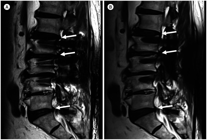
금속은 금속 주변 스핀의 세차주파수를 변화 시켜 주파수부호화(frequency encoding) 과정에서의 주파수와 위치 정보 간의 선형적 관계를 훼손하여, 영상을 왜곡시키고(geometric distortion), signal pile-up 혹은 신호 소실을 일으킨다(Fig. 1). Signal pile-up은 여러 개의 voxel에서 나온 신호가 동시에 하나의 위치로 등록되어 발생하고, 신호 소실은 voxel의 신호가 정상적으로 등록되어야 할 위치로부터 다른 곳으로 이동해 버리기 때문에 발생한다. 이러한 변화는 주파수부호화 과정을 거치는 in-plane과 through-plane 모두에서 나타날 수 있다. Through-plane의 경우, 자장의 불균질로 인해 선택된 절편(slice)의 위치가 이동하거나, 절편의 두께가 얇거나 혹은 두껍게 바뀔 수 있고, 또는 평평한 slice가 감자 칩처럼 굴곡지게 변화할 수 있으며, 심한 경우는 하나의 절편이 여러 개로 갈라질 수도 있다. 그러나, 위상부호화(phase encoding) 방향으로 금속 인공물 발생은 드물다. 금속으로 인해 불균질해진 자장에서 모든 스핀은 비슷한 정도의 위상 변화(phase shift)를 받기 때문이다(8,9,10).
Fig. 1. 74-year-old man with posterior fusion of L2-3-4.
A, B. Sagittal T2-weighted image shows the signal void and pile-up next to the screws (A). The out-pouching of the intervertebral discs (arrows) can be identified on this image (A). However, it may be a pseudo-lesion associated with a geographic distortion considering the fact that the out-pouching of the intervertebral disc (arrows) is less prominent on the slice encoding for metal artifact correction combined with T2-weighted image (B).
Fat Suppression의 실패
Frequency selective fat suppression은 가장 흔히 사용하는 fat suppression 방법이다. 이는 지방 양성자와 물 양성자의 자기공명 주파수의 차이를 이용하여 지방의 주파수에 맞춘 saturation 펄스를 사용함으로써, 지방 신호를 선택적으로 억제하는 기법이다. 그러나, 금속으로 인한 주자장의 불균질은 지방의 공명 주파수를 saturation 펄스의 바깥으로 이동시키고 이로 인해 fat suppression이 실패하게 된다. 간혹, 물의 공명 주파수가 fat saturation 펄스의 주파수 내로 이동되어 물 신호가 소실되기도 한다(6,7)
금속 인공물 발생에 영향을 주는 요소
금속물의 모양, 크기, 재질, 위치
금속물의 모양, 크기, 재질, 그리고 위치는 금속 인공물 발생 정도에 영향을 미친다. 둥글고 대칭적인 모양의 금속물에 비해 비정형적인 모양의 금속물은 좀 더 심한 금속 인공물을 만들고, 큰 금속물은 작은 금속물에 비해 좀 더 큰 인공물을 만든다. 금속물의 재질은 금속물 발생의 정도에 보다 많은 영향을 미친다(Fig. 2). 최근 자주 사용되고 있는 금속에는 cobalt-chromium, titanium, stainless-steel 등이 있고, 이중 cobalt-chromium은 무릎이나 고관절과 같은 마모가 심할 것으로 예상되는 관절에 주로 사용하고, titanium은 그보다 마모가 적을 것으로 예상되는 위치의 구조물을 지지하기 위해(예를 들어 골절 치료에 사용되는 plate) 주로 사용한다(11,12). Cobalt-chromium (900~1370 ppm)이나 stainless-steel (3000~5000 ppm)의 magnetic susceptibility는 titanium (182 ppm)에 비해 매우 강하기 때문에, cobalt-chromium 혹은 stainless-steel은 MR 영상에서 심한 인공물을 만들고, titanium은 보다 작은 인공물을 만든다(4,5). 금속물의 위치도 인공물 발생 정도에 영향을 미치는데, 금속물이 주자장(B0)의 방향과 평행으로 놓였을 때는 그렇지 않을 때에 비해 보다 작은 인공물을 만든다. 따라서 금속물의 방향에 맞추어 주파수부호화 방향을 조절하는 것이 인공물 발생 정도를 줄이는데 도움이 된다(13)
Fig. 2. Types of metallic materials.
A, B. T1-weighted images with spinal fusion using titanium in 59-year-old man (A) and using stainless steel in 63-year-old man (B). There are more metal artifacts in (B) than in (A).
자장의 세기
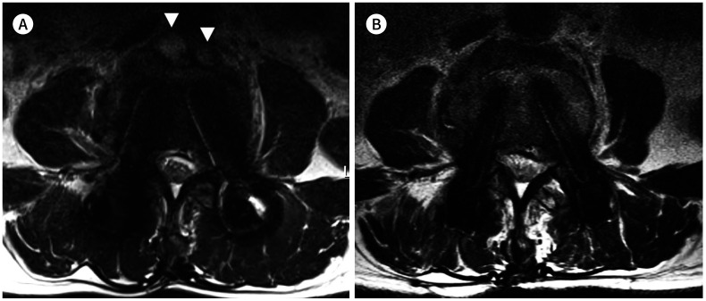
1.5 T 비해 3 T에서의 자장의 비균질도가 두 배 증가하기 때문에 3 T MR에서 금속 인공물이 더 심하게 발생한다. 따라서 금속물이 삽입되어 있는 경우에서는 1.5 T MR 장비를 사용하는 것이 현명하다(Fig. 3). 최근 금속 인공물을 줄이는 기술이 개발되어 3 T MR에서도 금속 인공물 감소가 가능하긴 하나, 과도한 gradient power와 잦은 RF, 그리고 높은 specific absorption rate (이하 SAR)에 의해 환자가 느끼는 열감 등의 문제가 남아 있다(14). 최근 7 T MR 장비 개발과 함께 금속의 안정성에 대해 평가 중이며, endovascular graft나 몇몇 정형외과적 금속물은 불안정할 수 있다는 평가를 받았다(15).
Fig. 3. 63-year-old man with postoperative spinal infection.
A, B. Axial T2-weighted image (TR/TE = 2000/100, receiver bandwidth = 230 Hz/pixel) obtained by a 3 T MR machine shows the prevertebral abscesses (arrowheads) (A). The follow-up MRI outcome after a 3-month antibiotic therapy has been imaged by a 1.5 T machine (B). The image (TR/TE = 3550/123, receiver bandwidth = 163 Hz/pixel) shows resolution of prevertebral abscesses. The metal artifact of the screws (B) is smaller than that in the initial MRI with 3 T (A).
TE = echo time, TR = repetition time
자기공명 펄스열(Pulse Sequence)
경사에코(gradient echo) 영상은 금속물로 인해 발생한 주자장의 불균질로 인해 고속화된 intravoxel dephasing를 보상하는 방법이 없기 때문에, 금속 주변에 비교적 큰 signal void가 나타난다. 반면, 스핀에코(spin echo) 영상은 180도 refocusing 펄스를 이용하여 흩어진 spin의 위상을 다시 한곳으로 모아 주기 때문에 주자장의 불균질에 상대적으로 안정적이다. 보다 짧은 echo time (이하 TE)은 스핀의 dephasing을 보다 빨리 refocusing 해 주기 때문에, T2 강조 영상에 비해 짧은 TE를 사용하는 T1 혹은 proton density 강조 영상에서 금속 인공물 발생이 덜하다(16,17). 한편, 촬영 시간을 줄이기 위해 일상적으로 사용하는 고속스핀에코(fast spin echo 혹은 turbo spin echo)에서 echo train length를 높이면 금속 인공물이 더 심해진다는 최근 보고가 있다(18). 3D 영상의 경우, 두 방향을 위상부호화로 얻기 때문에 고식적인 2D 영상에 비해 금속 인공물이 덜 발생한다. 3D 영상은 excitation 펄스에 따라 slab-selective와 non-selective로 나눌 수 있는데, slap selective excitation을 사용하는 경우는 through-plane 방향으로 왜곡이 나타날 수 있다. Non-selective excitation 사용은 이러한 through-plane 방향으로의 영상의 왜곡은 없으나 충분한 bandwidth의 RF 펄스를 필요로 하고, through-plane 방향으로 aliasing artifact가 나타날 수 있다(6,19).
금속 인공물 감소를 위한 기본 전략
기본적으로 낮은 자장의 MR 장비를 사용하고 경사에코 펄스 열보다는 스핀에코 펄스 열을 사용하는 것이 금속 인공물 발생을 줄이는데 도움이 된다.
금속 인공물 감소를 위한 특별한 방법
높은 Receiver Bandwidth 사용하기
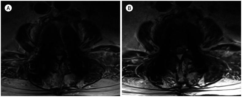
Receiver bandwidth를 높이는 것, 다시 말해 readout 방향으로 gradient를 높이는 것은 inplane artifact를 줄이는 가장 효과적인 방법 중의 하나이다. Receiver bandwidth를 높이면, readout 방향으로 하나의 pixel에 포함되는 주파수의 폭이 증가하게 되어, 국소적인 주파수 오류 (local frequency error)로 인한 readout 방향으로의 misregistration이 줄어들기 때문이다(6) (Figs. 4, 5). 일반적으로, 금속 인공물 감소를 위해서 receiver bandwidth를 두세 배정도(약 500~800 Hz/pixel)로 늘리는 것을 추천하다. 그러나, 높은 receiver bandwidth는 사용하면, 신호대잡음비(signal-to-noise ratio)가 감소한다는 단점이 있다. Scan average를 높이면 촬영 시간이 증가하기는 하나 신호대잡음비 감소를 보완할 수 있다. 한편으로 receiver bandwidth를 높이면, echo spacing을 줄일 수 있고, 이를 통해 T2 decay에 의한 신호 소실을 줄여 영상을 보다 선명하게 만들 수 있다는 장점이 생긴다(6,10).
Fig. 4. Effect of receiver bandwidth.
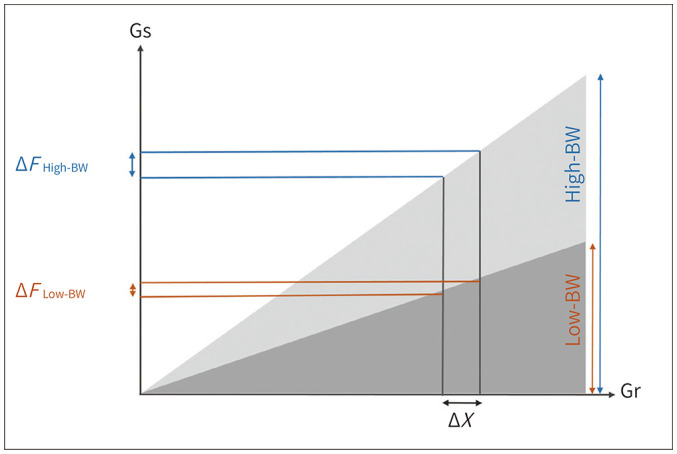
Each voxel is encoded by a wider frequency range in a high receiver bandwidth than in a low bandwidth. Therefore, the local frequency errors generated by metal implant do not significantly influence the spatial encoding in a high receiver bandwidth.
BW = bandwidth, Gr = readout gradient axis, Gs = slice selection gradient axis
Modified from Khodarahmi et al. Semin Musculoskelet Radiol 2019; 23:e68-e81, with permission of Thieme (10)
Fig. 5. 66-year-old woman with posterior fusion of L3-4-5.
A, B. The receiver bandwidths for the two axial T2-weighted images are 150 Hz/pixel (A) and 550 Hz/pixel (B), and the other parameters for (A) and (B) are the same. The metal artifact size for the bilateral screws is considerably larger in (A) than in (B).
높은 RF Bandwidth 사용하기
RF 펄스의 bandwidth를 높이면 through-plane distortion을 줄일 수 있다. 그러나, SAR이 증가하고 영상이 흐려진다는 단점이 있다(20).
Matrix 크게 하기
일정한 촬영 범위에서 matrix의 수를 증가시키면 voxel 크기가 작아져서 intravoxel dephasing으로 인한 신호 소실과 in-plane distortion을 줄일 수 있다. 다시 말해, 금속물이 있는 경우 하나의 voxel 안에 들어 있는 스핀들의 세차 속도는 균일하지 않기 때문에, voxel의 크기를 줄이면 불균일한 세차 속도를 가지는 스핀들의 수가 줄어들어 이에 따른 intravoxel dephasing이 감소하게 되는 것이다. 그러나, receiver bandwidth의 증가와 같은 다른 변수의 변화 없이, matrix 크기의 변화만으로는 in-plane distortion을 줄이는 것에는 한계가 있다. 주의할 것은 위상부호화 방향이 아닌 주파수부호화 방향으로 matrix를 크게 하는 것이 금속 인공물 발생을 줄이는데 도움이 된다. 그렇다고 주파수부호화 방향으로만 matrix 크기를 늘리면 truncation artifact가 발생할 수 있으므로, 위상부호화 방향으로 적어도 주파수부호화 matrix의 60%~80%를 받아야 한다(6).
절편 두께 줄이기
Matrix를 크게 하는 것과 같은 맥락으로 절편 두께를 줄이는 것 또한 voxel의 크기를 작게 하여 intravoxel dephasing으로 인한 신호 소실을 줄일 수 있다. 절편 두께를 줄이기 위해서는 보다 강한 slice selection gradient를 적용해야만 하고, 절편의 두께가 감소되면 촬영 시간이 증가하고 신호대잡음비는 감소한다(6,10).
Fat Suppression 방법의 선택
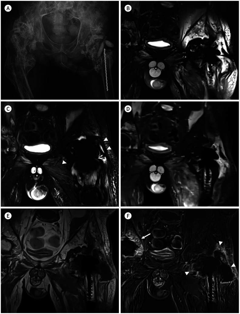
Frequency selective fat suppression은 비교적 신호대잡음비의 감소 없이 빠른 시간 내에 효과적으로 지방 소거를 할 수 있어, 흔히 사용되는 기법이다. 그러나, 이는 주자장의 균질도에 많은 영향을 받는다. 반면, short tau inversion recovery (이하 STIR)는 물과 지방의 주파수의 차이가 아닌 두 물질 간의 T1 값의 차이를 이용하여 지방을 소거하는 기법이기 때문에, 금속으로 인한 주자장 불균질로 인한 영향이 작아서, 금속 인공물이 있을 때 frequency selective fat suppression에 비해 보다 균질한 fat suppression을 보인다(Fig. 6) (21). 그러나, STIR은 신호대잡음비가 낮기 때문에, 연골 등의 평가는 frequency selective fat suppression과 비교하여 정확성이 떨어진다(22). 또한, 조영제를 사용한 경우에 조영증강된 조직은 T1 이완 시간이 감소하여 STIR 영상에서 지방과 함께 조영증강된 조직의 신호가 억제될 수 있기 때문에, STIR은 T1 조영증강제를 사용한 후에는 적용할 수 없다는 단점이 있다.
Fig. 6. 59-year-old man with septic arthritis at left hip joint.
A. Simple radiography shows the presence of antibiotic beads, spacer, and metallic device at the left hip joint and femur. Right hip joint and right femur are deformed.
B. The frequency-selective fat suppressed T2 weighted image applied with SEMAC shows incomplete fat suppression around the metallic implant.
C. The water-only image from Dixon technique shows more homogenous fat suppression than that in (B). However, it shows zebra artifact or Moire fringes (arrowheads) around the metallic instrument.
D. Although the short tau inversion recovery with SEMAC shows more homogenous fat suppression than that in (B) and (C), its signal-to-noise ratio is relatively poor.
E, F. Compared with T1 weighted image with SEMAC after contrast administration (E), subtraction image (F) between pre-contrast and post-contrast T1 weighted images with SEMAC shows obvious contrast-enhancement around the left hip joint (arrowheads) and right acetabulum (arrow).
SEMAC = slice-encoding for metal artifact correction
Dixon 기법(chemical-shift-based separation of water and fat signal)은 물과 지방의 위상의 차이를 이용하여, 물과 지방이 같은 위상에 있을 때의 영상(in-phase 영상)과 정반대의 위상에 있을 때의 영상(opposed-phase 영상)을 얻은 후 이차적으로 water-only 영상과 fat-only 영상을 reconstruction하는 방법이다. Dixon은 STIR에 비해 신호대잡음비가 높고 조영증강 후 T1 강조 영상에 사용할 수 있고, frequency selective fat suppression과 비교해서 보다 균일한 fat suppression 영상을 얻을 수 있다(23,24). 그러나 자장의 불균질이 심할 경우에는 밝고 어두운 선들이 반복되는 zebra artifact 혹은 Moire fringe가 나타날 수 있다.
조영제 사용 후 fat suppression을 하는 방법에는 조영증강 전후의 T1 강조 영상을 subtraction하는 방법이 있다. 조영제 사용 전과 후의 영상 촬영 시간 간격 동안에 발생한 환자의 움직임이 없다면 균일하게 지방을 소거할 수 있는 방법이다(25). 단, 이 방법으로 원래 영상에서 나타나는 geometric distortion이나 신호 소실은 극복할 수 없다.
위상부호화 방향과 주파수부호화 방향 바꾸기
위상부호화 과정은 불균질해진 자장에 영향을 덜 받기 때문에, 관찰하고자 하는 주요한 부위가 인공물에 의해 가려지지 않도록 위상부호화 방향과 주파수부호화 방향을 서로 바꾸는 것이 도움이 될 수 있다. 그러나, 위상부호화 과정은 aliasing artifact를 줄이기 위해 위상부호화 방향으로 oversampling이 필요할 수 있으므로 경우에 따라 촬영 시간이 늘어난다는 단점이 있다(6).
금속 인공물 감소를 위한 특별한 방법
최근 MR에서 금속 인공물 감소를 위해 특별히 개발된 기법으로 view-angle-tilting (이하 VAT)과 multispectral imaging (이하 MSI)가 있다. MSI에는 multi-acquisition variable-resonance image combination (이하 MAVRIC)과 slice-encoding for metal artifact correction (이하 SEMAC) 그리고, 이들이 조합된 MAVRIC-selective (이하 MAVRIC-SL)와 multiple slab acquisition with VAT based on SPACE (이하 MSVAT-SPACE)가 있다. 이러한 기법들은 금속 인공물을 줄이는 데 탁월하다. 그러나, 촬영 시간의 증가, 신호대잡음비의 감소, spatial resolution의 감소 등의 단점을 가지고 있다(26).
View Angle Tilting (VAT)
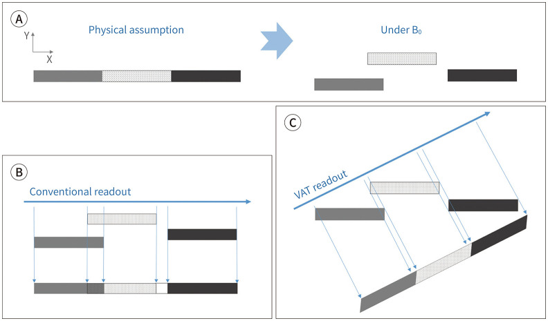
VAT는 in-plane distortion을 줄이기 위해 개발되었다(27). 신호를 read-out 하는 과정에서 주파수부호화 gradient와 함께, 절편선택(slice-selection) 방향으로 절편선택 gradient와 같은 amplitude의 gradient를 추가하여, readout-encoding 방향을 절편선택 방향으로 기울어 줌으로써 in-plane distortion (spatial misregistration)을 상쇄시키는 방법이다(Fig. 7). VAT는 촬영 시간의 증가 없이 금속 인공물을 감소시킬 수는 있으나, 주파수부호화 방향으로 영상이 흐려진다는 단점이 있다. 이는 틀어진 voxel로 인해 경계 부분에 partial volume effect가 생기기 때문으로 금속 주변에서만이 아닌 영상 전체에서 나타난다(28). Receiver bandwidth를 500 Hx/pixel 이상으로 높인 경우에는, VAT를 추가함으로써 얻는 금속 인공물 감소 효과는 미미하다는 보고도 있다(26). VAT는 through-plane distortion은 교정하지 못한다. 그런 까닭에 VAT는 주로 through-plane distortion을 교정하는 SEMAC와 함께 사용된다(29).
Fig. 7. Concepts of VAT.
A, B. Three materials with different magnetic susceptibility are assumed to be aligned in a row (A). The materials are displaced under the magnetic field and demonstrate signal overlap and signal void (A and B).
C. VAT by applying the gradient in slice selection direction during the readout results in tilting the angle of the readout direction and resolves the in-plane artifacts. However, the image blurring can be seen at the margins of the materials.
VAT = view angle tilting
Modified from Khodarahmi et al. Semin Musculoskelet Radiol 2019;23:e68-e81, with permission of Thieme (10)
Slice Encoding for Metal Artifact Correction (SEMAC)
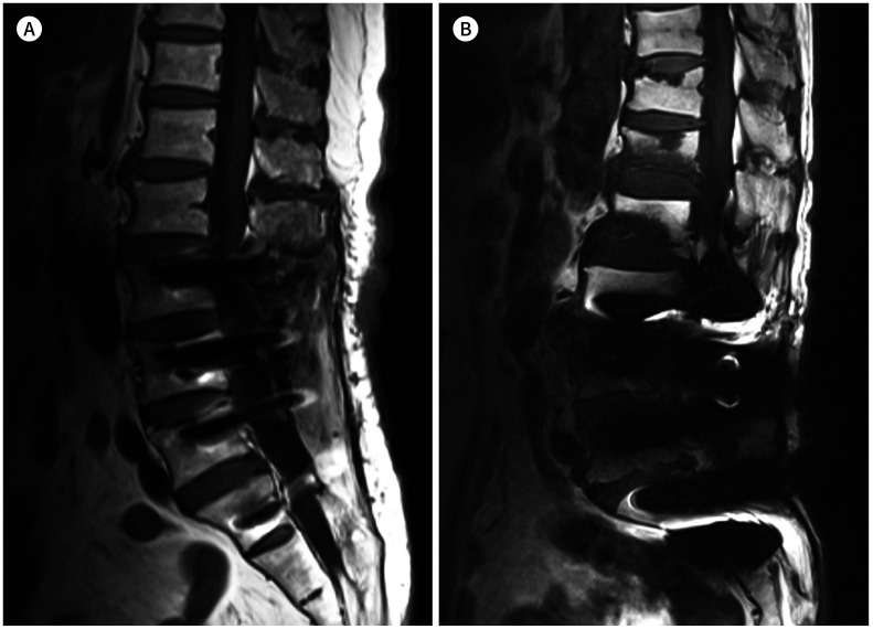
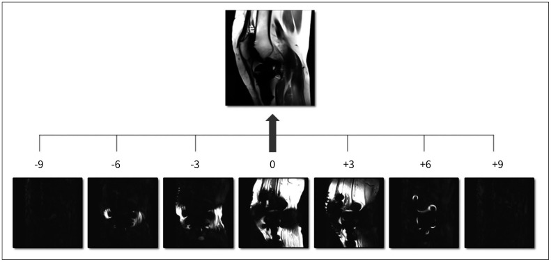
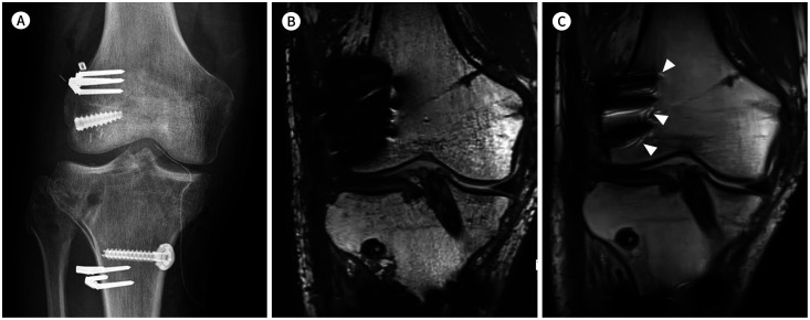
SEMAC는 2D 영상에서의 through-plane distortion을 교정하기 위해 개발되었다. 각각의 영상 절편에서 절편선택 방향으로 위상부호화를 추가하여 얻어진 영상들을 linear 혹은 quadratic summation (sum-of-squares)을 통해 한 장의 영상을 만듦으로써 through-plane으로 생긴 artifact를 제거하는 것이다(Fig. 8) (29). 여기에 VAT를 함께 적용하여 in-plane distortion을 제거한다. 추가하는 위상부호화 step의 수를 SEMAC factor 혹은 SEMAC step이라고 하고, SEMAC factor가 크면 심한 금속 인공물 제거가 용이하나 촬영 시간이 길어진다. 따라서 금속 인공물의 발생정도에 따라 SEMAC factor의 최적화가 필요하다(30). 금속 인공물의 발생 정도를 결정하는 중요 요인 중의 하나가 금속의 종류로써, 최근 3 T MR 장비를 이용한 팬텀 연구에 따르면 stainless-steel이나 cobalt-chromium-molybdenum은 SEMAC factor 26 정도로 강하게, titanium이나 zirconium은 SEMAC factor 6 정도로 약하게 적용하는 것이 적절하다고 한다(31). SEMAC에서는 ripple artifact 혹은 pile-up artifact라고 하는 특징적인 인공물이 발생할 수 있다(Fig. 9). 이는 추가로 얻은 절편을 합치는 과정 발생하는 것으로 금속 주변으로 residual intensity fluctuation으로 나타난다. 이를 줄이기 위해서는 추가로 얻는 절편을 overlap 하는 것이 도움이 되나, 촬영시간이 증가한다는 단점이 발생한다(32). 최근 SEMAC를 척추 영상에 적용한 연구에서, SEMAC는 금속 인공물 감소에 탁월하였으나 고식적인 고속스핀에코에서는 보이지 않던 central spinal canal에 신호 소실이 발생하였다고 한다(Fig. 10) (33).
Fig. 8. SEMAC with SEMAC factor of 19.
Individual encoding step images are obtained by additional phase-encoding steps in a slice-selection direction. The combination of these partitions makes a final SEMAC image.
SEMAC = slice encoding for metal artifact correction
Fig. 9. 39-year-old man with ACL, PLC, and medial collateral ligament repair.
A. Simple radiography shows the several staples and anchor for ACL and PLC reconstruction.
B. Conventional T2-weighted image shows the signal void and signal pile-up around the metallic devices inserted at the lateral femoral condyle.
C. SEMAC T2-weighted image shows a metal artifact, which is smaller than that in (A), at the lateral femoral condyle. The typical ripple artifact around the metallic implants is present on the SEMAC image (arrowheads).
ACL = anterior cruciate reconstruction, PLC = posterolateral corner reconstruction, SEMAC = slice-encoding for metal artifact correction
Fig. 10. 75-year-old woman with posterior fusion of L3-4-5 and interbody fusion of L3-4, L4-5, and L5-S1.
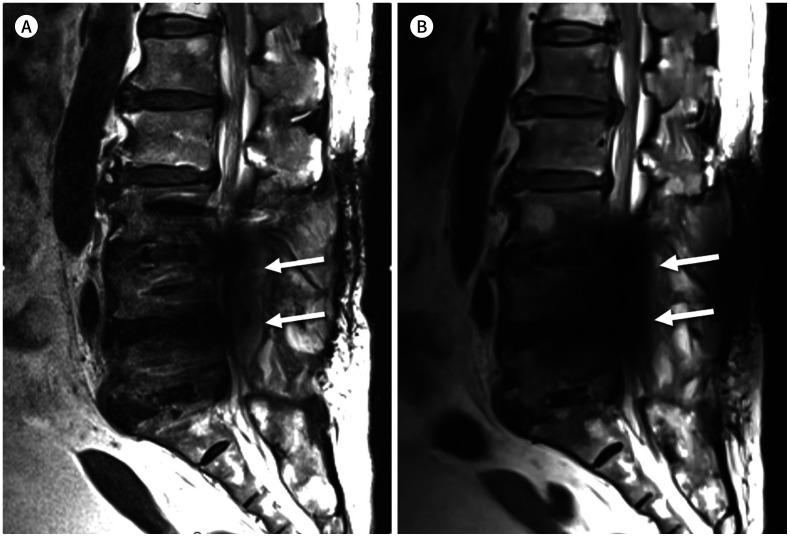
A, B. Sagittal T2-weighted image with high receiver bandwidth (545 Hz/pixel) shows fluid collection (arrows) at the posterior epidural space of L4-5 (A). However, this fluid collection is obscured by the signal void (arrows) at the spinal central canal on slice-encoding for metal artifact correction T2-weighted image (B).
Multiacquisition Variable-Resonance Image Combination (MAVRIC)
MAVRIC은 in-plane distortion와 through-plane distortion을 교정하는 3D 영상이다(34). 3D 영상은 두 개의 축을 위상부호화를 통해 얻기 때문에, 2D에 비해 through-plane distortion에 강하다. 그러나, non-selective RF 펄스를 사용하기 때문에 금속 주변의 스핀들의 세차주파수를 모두 포함하지 못하여 off-resonance가 발생하고 이로 인해 신호 소실이 나타난다. MAVRIC은 이러한 문제를 해결하기 위해, 좁은 bandwidth와 다양한 공명 주파수를 가지는 여러 개의 RF 펄스(spectral bin)를 사용하여, 여러 개의 3D slap을 얻는다. 이후 얻어진 여러 개 3D slap을 모두 조합하여(quadrature summation 혹은 maximum-intensity projection) 금속 인공물이 감소한 하나의 3D 영상을 얻게 되는 것이다(5,35). 일반적으로 하나의 spectral bin은 가우스(Gaussian) 모양이고 2.25 kHz의 폭을 가지며, 각각의 spectral bin의 간격은 1 kHz로 서로 부분적으로 겹쳐진다(17,36). SEMAC factor와 마찬가지로 spectral bin의 수는 촬영 시간에 영향을 미치므로 금속의 종류에 따라 spectral bin의 수를 조절하는 것이 바람직하다. 그러나, SEMAC와는 달리 spectral bin 수 조절은 아직 상용화되지 않은 상태이다. MAVRIC은 촬영 시간이 길고, non-selective RF펄스를 사용으로 인해 through-plane 방향으로 aliasing artifact도 발생할 수 있으며, 영상이 흐리다는 단점이 있다(35).
Hybrid Technique
MAVRIC-SL은 volume-selective 3D MSI (VS-3D-MSI)로 불리었던 것으로, MAVRIC에서 사용하는 각각의 spectral bin에 SEMAC에서 사용하는 절편선택 gradient를 적용하고, read-out 동안 VAT를 추가하는 것이다(Fig. 11) (6,7,36,37). 한편 MSVAT-SPACE는 SEMAC와 VAT를 SPACE에 적용시킨 것으로, SPACE 단독에 비해 영상의 질이 우수하다(38).
Fig. 11. 55-year-old man with acetabular fixation.
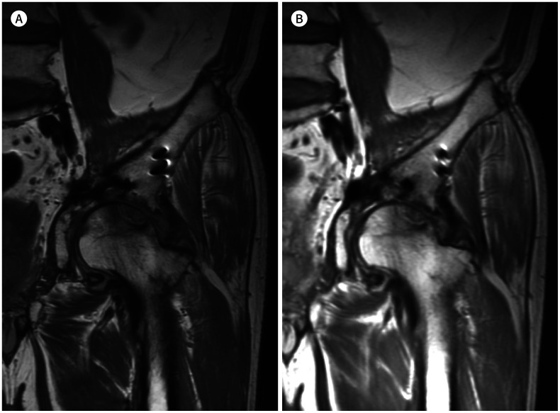
A, B. Compared with conventional coronal proton density-weighted image (A), the artifact size of the metallic instruments is small in MAVRIC-SL (B). However, MAVRIC-SL demonstrates image blurring.
MAVRIC-SL = multi-acquisition variable-resonance image combination-selective
Off-Resonance Suppression
Off-resonance suppression은 excitation RF 펄스와 refocusing RF 펄스의 gradient와 bandwidth를 서로 달리하여, 두 가지 펄스의 중첩되는 범위 안에 있는 스핀에서 나오는 신호만으로 영상을 만든 것이다(39). 이는 SEMAC과 MAVRIC과 함께 적용되어서 촬영 시간을 줄이면서 aliasing artifact를 없애는데 도움을 준다. 그러나, off-resonance suppression은 신호의 소실이 많고, 영상이 균일하지 않다는 단점이 있다(39).
영상 획득 시간을 줄이는 방법
SEMAC와 MAVRIC은 금속 인공물 발생을 줄이는데 탁월하나, 절편선택 방향으로 추가하는 위상부호화와 여러 개의 spectral bin 사용으로 인해 촬영 시간이 매우 길다는 무시할 수 없는 단점이 있다. 실제 임상에서 사용할 수 있을 정도로 촬영 시간을 줄이기 위해서는, partial Fourier encoding이나 parallel imaging 같은 알고리즘이 필요하다(5,40). 최근에는 보다 빠르게 영상을 얻을 수 있는 compressed sensing이 개발되었다(41). 이는 k space의 pseudo-randomized undersampling을 통해 촬영 시간을 단축하고, iterative reconstruction을 통해 undersampling 때문에 나빠진 영상의 질을 회복시키는 기술로, SEMAC과 MAVRIC에 모두 성공적으로 적용되었다(Fig. 12). SEMAC에 compressed sensing을 적용한 연구에 따르면, 1.5T MR 장비로 k-space sampling rate 12.5%를 적용하여 SEMAC factor 19를 주었음에도 불구하고, 영상의 질은 유지하면서 촬영 시간은 5분 이내로 단축시켰다(42,43,44).
Fig. 12. 75-year-old woman with posterior fusion of L4-5.
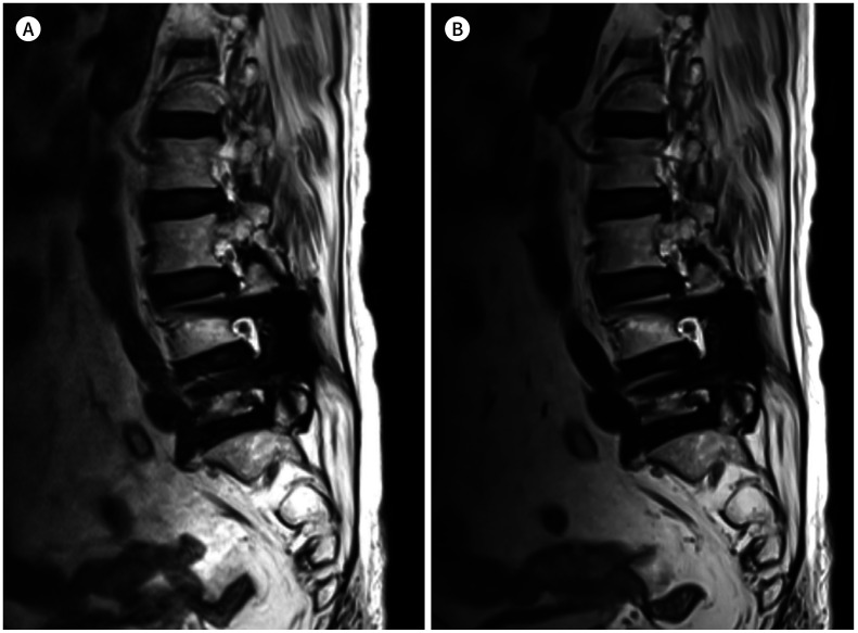
A, B. T2-weighted images with SEMAC (A) and T2-weighted images with compressed-sensing SEMAC (B) show similar image quality. The acquisition times for compressed-sensing SEMAC (B) is particularly shorter than that for SEMAC (A) and are quite different: 6 minutes 35 seconds for T2-weighted images with SEMAC and 3 minutes 10 seconds for compressed-sensing SEMAC.
SEMAC = slice-encoding for metal artifact correction
결론
이제까지 금속 인공물의 발생 원인과 발생 양상, 금속 인공물을 줄이기 위한 일반적인 방법과 특별한 기법에 대해 알아보았다. 금속 인공물을 줄이기 위해 가장 먼저 고려해야 하는 것은 3 T가 아닌 1.5 T MR 장비로 영상을 획득하는 것이다. 삽입된 금속이 titanium처럼 magnetic susceptibility가 낮을 경우, receiver bandwidth를 증가하거나, matrix 증가, 절편 두께 줄이기, Dixon 기법의 사용 등을 통해 어느 정도의 금속 인공물을 감소시킬 수 있다. 그러나 슬관절 치환술이나 혹은 고관절 치환술에 삽입하는 cobalt-chromium의 경우는 magnetic susceptibility가 높으므로, 가능하다면 SEMAC나 MAVRIC을 사용하는 것이 바람직하다. 최근에 SEMAC에 compressed sensing을 적용하는 것이 상용화됨에 따라, 최대한의 금속 인공물 소거가 합리적인 촬영 시간 내에 가능해져 보다 정확한 검사를 보다 보편적으로 사용할 수 있을 것이라 기대한다.
Acknowledgments
This material is based upon work supported by the Ministry of Trade, Industry & Energy (MOTIE, Korea) under industrial Technology Innovation Program. No.10062728.
Footnotes
- Conceptualization, C.H.J.
- data curation, all authors
- funding acquisition, L.S.J.
- investigation, all authors
- project administration, C.H.J.
- supervision, C.H.J.
- validation, C.H.J., L.Y.H.
- visualization, L.S.J., L.Y.H.
- writing—original draft, C.H.J.
- writing—review & editing, L.S.J., L.Y.H.
Conflicts of Interest: The authors have no potential conflicts of interest to disclose.
References
- 1.Thiele K, Perka C, Matziolis G, Mayr HO, Sostheim M, Hube R. Current failure mechanisms after knee arthroplasty have changed: polyethylene wear is less common in revision surgery. J Bone Joint Surg Am. 2015;97:715–720. doi: 10.2106/JBJS.M.01534. [DOI] [PubMed] [Google Scholar]
- 2.Rajaee SS, Campbell JC, Mirocha J, Paiement GD. Increasing burden of total hip arthroplasty revisions in patients between 45 and 64 years of age. J Bone Joint Surg Am. 2018;100:449–458. doi: 10.2106/JBJS.17.00470. [DOI] [PubMed] [Google Scholar]
- 3.Talbot BS, Weinberg EP. MR imaging with metal-suppression sequences for evaluation of total joint arthroplasty. Radiographics. 2015;36:209–225. doi: 10.1148/rg.2016150075. [DOI] [PubMed] [Google Scholar]
- 4.Schenck JF. The role of magnetic susceptibility in magnetic resonance imaging: MRI magnetic compatibility of the first and second kinds. Med Phys. 1996;23:815–850. doi: 10.1118/1.597854. [DOI] [PubMed] [Google Scholar]
- 5.Koch KM, Hargreaves BA, Pauly KB, Chen W, Gold GE, King KF. Magnetic resonance imaging near metal implants. J Magn Reson Imaging. 2010;32:773–787. doi: 10.1002/jmri.22313. [DOI] [PubMed] [Google Scholar]
- 6.Jungmann PM, Agten CA, Pfirrmann CW, Sutter R. Advances in MRI around metal. J Magn Reson Imaging. 2017;46:972–991. doi: 10.1002/jmri.25708. [DOI] [PubMed] [Google Scholar]
- 7.Ariyanayagam T, Malcolm PN, Toms AP. Advances in metal artifact reduction techniques for periprosthetic soft tissue imaging. Semin Musculoskelet Radiol. 2015;19:328–334. doi: 10.1055/s-0035-1563734. [DOI] [PubMed] [Google Scholar]
- 8.Dillenseger J, Moliere S, Choquet P, Goetz C, Ehlinger M, Bierry G. An illustrative review to understand and manage metal-induced artifacts in musculoskeletal MRI: a primer and updates. Skeletal Radiol. 2016;45:677–688. doi: 10.1007/s00256-016-2338-2. [DOI] [PubMed] [Google Scholar]
- 9.Eustace S, Jara H, Goldberg R, Fenlon H, Mason M, Melhem ER, et al. A comparison of conventional spinecho and turbo spin-echo imaging of soft tissues adjacent to orthopedic hardware. AJR Am J Roentgenol. 1998;170:455–458. doi: 10.2214/ajr.170.2.9456963. [DOI] [PubMed] [Google Scholar]
- 10.Khodarahmi I, Isaac A, Fishman EK, Dalili D, Fritz J. Metal about the hip and artifact reduction techniques: from basic concepts to advanced imaging. Semin Musculoskelet Radiol. 2019;23:e68–e81. doi: 10.1055/s-0039-1687898. [DOI] [PubMed] [Google Scholar]
- 11.Zou YF, Chu B, Wang CB, Hu ZY. Evaluation of MR issues for the latest standard brands of orthopedic metal implants: plates and screws. Eur J Radiol. 2015;84:450–457. doi: 10.1016/j.ejrad.2014.12.001. [DOI] [PubMed] [Google Scholar]
- 12.Koff MF, Shah P, Koch KM, Potter HG. Quantifying image distortion of orthopedic materials in magnetic resonance imaging. J Magn Reson Imaging. 2013;38:610–618. doi: 10.1002/jmri.23991. [DOI] [PubMed] [Google Scholar]
- 13.Lee MJ, Kim S, Lee SA, Song HT, Huh YM, Kim DH, et al. Overcoming artifacts from metallic orthopedic implants at high-field-strength MR imaging and multi-detector CT. Radiographics. 2007;27:791–803. doi: 10.1148/rg.273065087. [DOI] [PubMed] [Google Scholar]
- 14.Aboelmagd SM, Malcolm PN, Toms AP. Magnetic resonance imaging of metal artifact reduction sequences in the assessment of metal-on-metal hip prostheses. Reports Med Imaging. 2014;7:65–74. [Google Scholar]
- 15.Feng DX, McCauley JP, Morgan-Curtis FK, Salam RA, Pennell DR, Loveless ME, et al. Evaluation of 39 medical implants at 7.0 T. Br J Radiol. 2015;88:2015063. doi: 10.1259/bjr.20150633. [DOI] [PMC free article] [PubMed] [Google Scholar]
- 16.Vandevenne JE, Vanhoenacker FM, Parizel PM, Butts Pauly K, Lang RK. Reduction of metal artefacts in musculoskeletal MR imaging. JBR-BTR. 2007;90:345–334. [PubMed] [Google Scholar]
- 17.Chang EY, Bae WC, Chung CB. Imaging the knee in the setting of metal hardware. Magn Reson Imaging Clin N Am. 2014;22:765–786. doi: 10.1016/j.mric.2014.07.009. [DOI] [PubMed] [Google Scholar]
- 18.Kumar NM, De Cesar Netto C, Schon LC, Fritz J. Metal artifact reduction magnetic resonance imaging around arthroplasty implants: the negative effect of long echo trains on the implant-related artifact. Invest Radiol. 2017;52:310–316. doi: 10.1097/RLI.0000000000000350. [DOI] [PubMed] [Google Scholar]
- 19.Hargreaves BA, Worters PW, Pauly KB, Pauly JM, Koch KM, Gold GE. Metal-induced artifacts in MRI. AJR Am J Roentgenol. 2011;197:547–555. doi: 10.2214/AJR.11.7364. [DOI] [PMC free article] [PubMed] [Google Scholar]
- 20.Bachschmidt TJ, Sutter R, Jakob PM, Pfirrmann CW, Nittka M. Knee implant imaging at 3 Tesla using highbandwidth radiofrequency pulses. J Magn Reson Imaging. 2015;41:1570–1580. doi: 10.1002/jmri.24729. [DOI] [PubMed] [Google Scholar]
- 21.Buckwalter KA. Optimizing imaging techniques in the postoperative patient. Semin Musculoskelet Radiol. 2007;11:261–272. doi: 10.1055/s-2008-1038315. [DOI] [PubMed] [Google Scholar]
- 22.Ulbrich EJ, Sutter R, Aguiar RF, Nittka M, Pfirrmann CW. STIR sequence with increased receiver bandwidth of the inversion pulse for reduction of metallic artifacts. AJR Am J Roentgenol. 2012;199:W735–W742. doi: 10.2214/AJR.11.8233. [DOI] [PubMed] [Google Scholar]
- 23.Cha JG, Jin W, Lee MH, Kim DH, Park JS, Shin WH, et al. Reducing metallic artifacts in postoperative spinal imaging: usefulness of IDEAL contrast-enhanced T1- and T2-weighted MR imaging--phantom and clinical studies. Radiology. 2011;259:885–893. doi: 10.1148/radiol.11101856. [DOI] [PubMed] [Google Scholar]
- 24.Cha JG, Hong HS, Park JS, Paik SH, Lee HK. Practical application of iterative decomposition of water and fat with echo asymmetry and least-squares estimation (IDEAL) imaging in minimizing metallic artifacts. Korean J Radiol. 2012;13:332–341. doi: 10.3348/kjr.2012.13.3.332. [DOI] [PMC free article] [PubMed] [Google Scholar]
- 25.Müller GM, Månsson S, Müller MF, Von Schewelov T, Nittka M, Ekberg O, et al. MR imaging with metal artifactreducing sequences and gadolinium contrast agent in a case-control study of periprosthetic abnormalities in patients with metal-on-metal hip prostheses. Skeletal Radiol. 2014;43:1101–1112. doi: 10.1007/s00256-014-1893-7. [DOI] [PubMed] [Google Scholar]
- 26.Khodarahmi I, Nittka M, Fritz J. Leaps in technology: advanced MR imaging after total hip arthroplasty. Semin Musculoskelet Radiol. 2017;21:604–615. doi: 10.1055/s-0037-1606135. [DOI] [PubMed] [Google Scholar]
- 27.Cho ZH, Kim DJ, Kim YK. Total inhomogeneity correction including chemical shifts and susceptibility by view angle tilting. Med Phys. 1988;15:7–11. doi: 10.1118/1.596162. [DOI] [PubMed] [Google Scholar]
- 28.Butts K, Pauly JM, Gold GE. Reduction of blurring in view angle tilting MRI. Magn Reson Med. 2005;53:418–424. doi: 10.1002/mrm.20375. [DOI] [PubMed] [Google Scholar]
- 29.Chen CA, Chen W, Goodman SB, Hargreaves BA, Koch KM, Lu W, et al. New MR imaging methods for metallic implants in the knee: artifact correction and clinical impact. J Magn Reson Imaging. 2011;33:1121–1127. doi: 10.1002/jmri.22534. [DOI] [PMC free article] [PubMed] [Google Scholar]
- 30.Deligianni X, Bieri O, Elke R, Wischer T, Egelhof T. Optimization of scan time in MRI for total hip prostheses: SEMAC tailoring for prosthetic implants containing different types of metals. Rofo. 2015;187:1116–1122. doi: 10.1055/s-0041-104893. [DOI] [PubMed] [Google Scholar]
- 31.Filli L, Jud L, Luechinger R, Nanz D, Andreisek G, Runge VM, et al. Material-dependent implant artifact reduction using SEMAC-VAT and MAVRIC: a prospective MRI phantom study. Invest Radiol. 2017;52:381–387. doi: 10.1097/RLI.0000000000000351. [DOI] [PubMed] [Google Scholar]
- 32.Den Harder JC, Van Yperen GH, Blume UA, Bos C. Ripple artifact reduction using slice overlap in slice encoding for metal artifact correction. Magn Reson Med. 2015;73:318–324. doi: 10.1002/mrm.25127. [DOI] [PubMed] [Google Scholar]
- 33.Park C, Lee E, Yeo Y, Kang Y, Lee JW, Ahn JM, et al. Spine MR images in patients with pedicle screw fixation: comparison of conventional and SEMAC-VAT sequences at 1.5 T. Magn Reson Imaging. 2018;54:63–67. doi: 10.1016/j.mri.2018.08.002. [DOI] [PubMed] [Google Scholar]
- 34.Hayter CL, Koff MF, Shah P, Koch KM, Miller TT, Potter HG. MRI after arthroplasty: comparison of MAVRIC and conventional fast spin-echo techniques. AJR Am J Roentgenol. 2011;197:W405–W411. doi: 10.2214/AJR.11.6659. [DOI] [PubMed] [Google Scholar]
- 35.Choi SJ, Koch KM, Hargreaves BA, Stevens KJ, Gold GE. Metal artifact reduction with MAVRIC SL at 3-T MRI in patients with hip arthroplasty. AJR Am J Roentgenol. 2015;204:140–147. doi: 10.2214/AJR.13.11785. [DOI] [PMC free article] [PubMed] [Google Scholar]
- 36.Koch KM, Brau AC, Chen W, Gold GE, Hargreaves BA, Koff M, et al. Imaging near metal with a MAVRIC-SEMAC hybrid. Magn Reson Med. 2011;65:71–82. doi: 10.1002/mrm.22523. [DOI] [PubMed] [Google Scholar]
- 37.Liebl H, Heilmeier U, Lee S, Nardo L, Patsch J, Schuppert C, et al. In vitro assessment of knee MRI in the presence of metal implants comparing MAVRIC-SL and conventional fast spin echo sequences at 1.5 and 3 T field strength. J Magn Reson Imaging. 2015;41:1291–1129. doi: 10.1002/jmri.24668. [DOI] [PMC free article] [PubMed] [Google Scholar]
- 38.Ai T, Padua A, Goerner F, Nittka M, Gugala Z, Jadhav S, et al. SEMAC-VAT and MSVAT-SPACE sequence strategies for metal artifact reduction in 1.5T magnetic resonance imaging. Invest Radiol. 2012;47:267–227. doi: 10.1097/RLI.0b013e318240a919. [DOI] [PubMed] [Google Scholar]
- 39.Den Harder JC, Van Yperen GH, Blume UA, Bos C. Off-resonance suppression for multispectral MR imaging near metallic implants. Magn Reson Med. 2015;73:233–243. doi: 10.1002/mrm.25126. [DOI] [PubMed] [Google Scholar]
- 40.Hargreaves BA, Chen W, Lu W, Alley MT, Gold GE, Brau AC, et al. Accelerated slice encoding for metal artifact correction. J Magn Reson Imaging. 2010;31:987–996. doi: 10.1002/jmri.22112. [DOI] [PMC free article] [PubMed] [Google Scholar]
- 41.Lustig M, Donoho D, Pauly JM. Sparse MRI: the application of compressed sensing for rapid MR imaging. Magn Reson Med. 2007;58:1182–1195. doi: 10.1002/mrm.21391. [DOI] [PubMed] [Google Scholar]
- 42.Fritz J, Ahlawat S, Demehri S, Thawait GK, Raithel E, Gilson WD, et al. Compressed sensing SEMAC: 8-fold accelerated high resolution metal artifact reduction MRI of cobalt-chromium knee arthroplasty implants. Invest Radiol. 2016;51:666–676. doi: 10.1097/RLI.0000000000000317. [DOI] [PubMed] [Google Scholar]
- 43.Fritz J, Fritz B, Thawait GK, Raithel E, Gilson WD, Nittka M, et al. Advanced metal artifact reduction MRI of metal-on-metal hip resurfacing arthroplasty implants: compressed sensing acceleration enables the timeneutral use of SEMAC. Skeletal Radiol. 2016;45:1345–1356. doi: 10.1007/s00256-016-2437-0. [DOI] [PubMed] [Google Scholar]
- 44.De Cesar Netto C, Fonseca LF, Fritz B, Stern SE, Raithel E, Nittka M, et al. Metal artifact reduction MRI of total ankle arthroplasty implants. Eur Radiol. 2018;28:2216–2227. doi: 10.1007/s00330-017-5153-9. [DOI] [PubMed] [Google Scholar]


