Abstract
Purpose.
We report the initial development of an image-based solution for robotic assistance of pelvic fracture fixation. The approach uses intraoperative radiographs, preoperative CT, and an end effector of known design to align the robot with target trajectories in CT. The method extends previous work to solve the robot-to-patient registration from a single radiographic view (without C-arm rotation) and addresses the workflow challenges associated with integrating robotic assistance in orthopaedic trauma surgery in a form that could be broadly applicable to isocentric or non-isocentric C-arms.
Methods.
The proposed method uses 3D-2D known-component registration to localize a robot end effector with respect to the patient by: (1) exploiting the extended size and complex features of pelvic anatomy to register the patient; and (2) capturing multiple end effector poses using precise robotic manipulation. These transformations, along with an offline hand-eye calibration of the end effector, are used to calculate target robot poses that align the end effector with planned trajectories in the patient CT. Geometric accuracy of the registrations was independently evaluated for the patient and the robot in phantom studies.
Results.
The resulting translational difference between the ground truth and patient registrations of a pelvis phantom using a single (AP) view was 1.3 mm, compared to 0.4 mm using dual (AP+Lat) views. Registration of the robot in air (i.e., no background anatomy) with five unique end effector poses achieved mean translational difference ~1.4 mm for K-wire placement in the pelvis, comparable to tracker-based margins of error (commonly ~2 mm).
Conclusions.
The proposed approach is feasible based on the accuracy of the patient and robot registrations and is a preliminary step in developing an image-guided robotic guidance system that more naturally fits the workflow of fluoroscopically guided orthopaedic trauma surgery. Future work will involve end-to-end development of the proposed guidance system and assessment of the system with delivery of K-wires in cadaver studies.
Keywords: image-guided surgery, 3D-2D registration, surgical robotics, known-component registration
1. INTRODUCTION AND PURPOSE
Pelvic fracture reduction and fixation is a surgical procedure for stabilizing pelvic bone fragments following traumatic injury. The surgeon stabilizes realigned anatomy by inserting Kirschner wires (K-wires), followed by cannulated screws.1,2 X-ray fluoroscopy guidance is typically used during the procedure in order to determine appropriate placement of K-wires. It is, however, often difficult to qualitatively reckon the 3D pose of the K-wire in the patient from a 2D fluoroscopic view, and the surgical staff is often exposed to prolonged radiation during the procedure.3
Robotic assistance has become an increasingly popular method for improving the accuracy, precision, workflow, and radiation exposure in various clinical applications.4,5,6 Most solutions rely on additional equipment for surgical tracking, which themselves have observed limited adoption in orthopaedic surgery due to workflow challenges, to register and drive the robot to preoperatively planned trajectories.4 An image-based (tracker-free) solution has recently been proposed for procedures that already use intraoperative imaging7 and may be better suited for integration with orthopaedic trauma surgery. The previously reported approach requires multiple views of the patient/robot (e.g., obtained via C-arm gantry rotation) that can be challenging due to the large size of the pelvis and the presence of surgical equipment and personnel in the limited OR space. Non-isocentric C-arms additionally require the gantry to be moved in multiple (unencoded) directions to keep structures of interest within the field of view (FOV).
To address the challenges associated with multi-view robot-to-patient registration, we propose a 3D-2D registration algorithm that registers a robot to a patient from a single view/position of the C-arm, without gantry rotation. The approach takes advantage of the large, feature-rich anatomy of the pelvis to register the patient from one radiograph obtained at a fixed-view of the C-arm. Accurate, encoded robotic manipulation is used to register the robot end effector using multiple low-dose radiographs obtained of the end effector at multiple poses, while maintaining the position of the C-arm at a fixed view. The geometric accuracy of the registrations was independently evaluated (i.e., for patient and robot) in phantom studies with respect to the more conventional approach using standard sets of dual views.
2. METHODS
2.1. Image-guided robotic positioning
The method builds on earlier work in image-guided robotic positioning of a drill guide for spine pedicle screw placement.8 Given a robot end effector (e) with respect to its base coordinate frame (b) the robot pose, , that aligns the component (κ) with the target K-wire trajectory (w), such that , is given by:
| (1) |
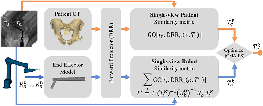
where is the preoperatively computed hand-eye calibration of the end effector to the instrument (κ) tip. The remaining unknowns are the instrument pose (, with respect to the C-arm coordinate frame), and the patient pose (, with respect to the C-arm), which are solved using the known-component registration (KC-Reg) algorithm7 – a two-step process that registers radiographs (e.g., AP, Lat, inlet, outlet, etc.) to a preoperative CT of the patient anatomy and a surgical instrument of known design. The covariance matrix adaptation evolution strategy (CMA-ES) is used to optimize the following registration objective functions:
| (2) |
| (3) |
such that the resulting instrument pose with respect to the patient in Eq. (1) is , where c is the coordinate-frame of the imaging system (C-arm), rθ is a radiograph acquired at C-arm gantry rotation (view) θ, and DRR is a digitally reconstructed radiograph rigidly transformed by T using the projective geometry of the C-arm at θ. The gradient orientation (GO) similarity metric provides robustness against content mismatch (e.g., since the radiographs additionally contain the end effector), while gradient correlation (GC) favors the high-intensity gradients associated with the robot end effector.10
2.2. Single-view registration of patient anatomy
Determining the 3D pose of an object from a single projection is challenging, especially for small objects and “degenerate” views (e.g., a view that stares down the drill guide axis). Large extended structures, however, are subject to varying magnification in the source-to-detector direction. The proposed workflow uses a single radiograph of the patient pelvis to solve for in Eq. (3), exploiting the rich gradient content and variations in magnification of the pelvis anatomy.9
2.3. Single-view registration of the robot
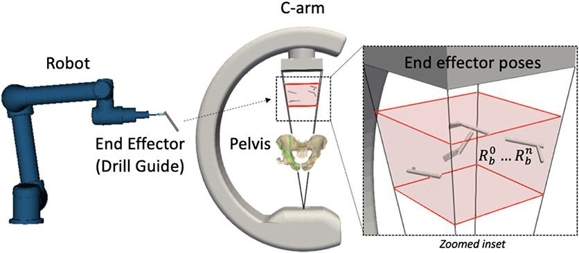
In contrast to the pelvic anatomy, the robot end effector presents a relatively small object with less information content (viz., fewer image gradients), that makes 3D pose estimation from a single view particularly challenging. To increase both the information content and the effective extent (size), precise robot motion was used to image the end effector at various locations within the FOV – specifically in the space between the patient and the detector (Figure 1). For each acquired radiograph ri, the corresponding instrument pose is simply given by the robot pose difference , where is an arbitrary / initial pose. The resulting set of radiographs and robot poses can be used to solve the objective below, substituting multiple C-arm views (θ) in Eq. (3) with robot poses (i = 1 … N):
| (4a) |
| (4b) |
where is the instrument pose with respect to the C-arm coordinate frame at initial robot pose .
Figure 1.
Single-view patient and robot registration. The robot end effector is positioned at multiple poses within the FOV and radiographs are acquired at each pose.
2.4. Phantom experiments
An anthropomorphic abdomen phantom with a natural human pelvis embedded in tissue-equivalent plastic (The Phantom Laboratory, Greenwich NY) was selected for phantom studies. A preoperative CT image of the phantom pelvis was acquired using the SOMATOM Definition (Siemens, Erlangen Germany) CT scanner, reconstructed on a 0.82×0.82×0.5 mm3 voxel grid using a standard bone-kernel.
End effector model.
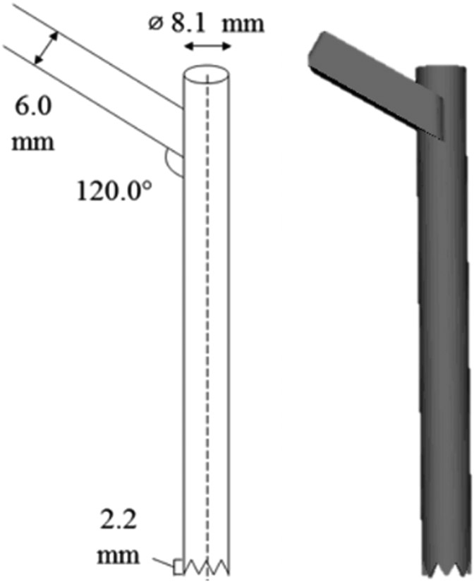
A drill guide instrument was affixed to a UR5 robot end effector (Universal Robots, Odense Denmark) and its 3D CAD model was created from manual measurements. The hand-eye calibration was obtained using the Park solver.11 A diagram of the drill-guide model with blueprint measurements is shown in Figure 3.
Figure 3.
Drill guide end effector model measurements with annotated measurements (left), and 3D rendering of the resulting triangulated mesh model (right).
Patient registration.
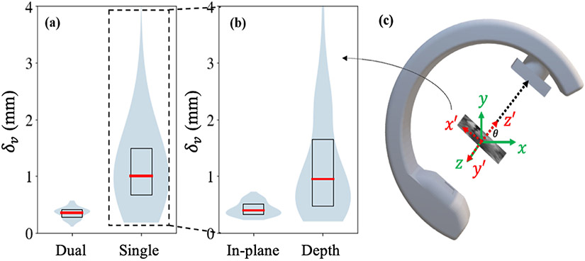
Four hundred projections of the phantom pelvis were obtained from cone-beam CT (CBCT) scans using a Cios Spin C-arm (Siemens, Erlangen Germany) covering a 16×16×16 cm3 region about the ilium and sacrum. Single and dual projections from this dataset were used to perform the 3D-2D patient registrations. “Ground-truth” (T£) for patient pose was defined from 3D-2D registrations of CT to a large number of projections from the projection datasets, ensuring that any projections used for the single- or dual-view registrations were not included in the set. Registration error was estimated by calculating the difference from ground truth, , such that δv is the norm of the translational component of Δv. For single-view registration, in-plane and depth components of Δv were calculated by projecting the Cartesian components onto the detector plane.
Robot registration.
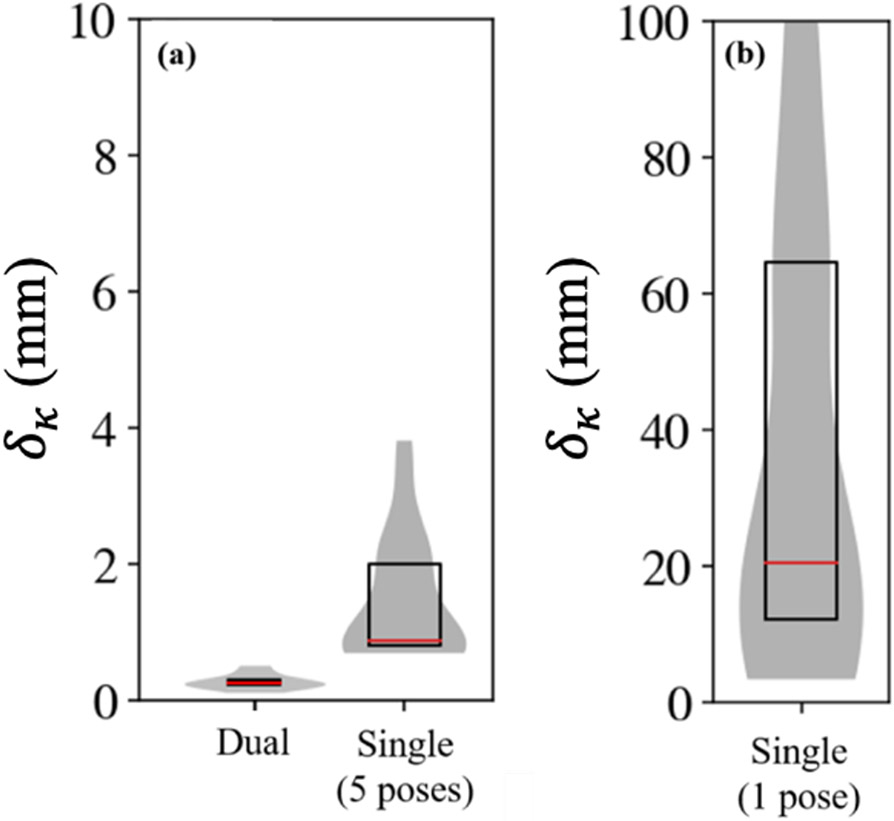
The robot end effector was placed close to the C-arm isocenter (used as starting pose, ) in air and 3D-2D registration was used to register the end effector CAD model to a large number of projections from an acquired CBCT in order to establish the “ground-truth” (). The robot was then moved to 8 random poses within the space between the patient and detector (Figure 1) and an AP radiograph was acquired at each pose (without rotating the C-arm gantry). Single-view robot registrations were performed with subsets of randomly selected poses of size N = 1 and N = 5. Error in geometric accuracy was calculated as deviation from truth, using , such that δκ is the norm of the translational component of Δκ.
3. RESULTS AND BREAKTHROUGH WORK
3.1. Geometric accuracy of single-view patient registration
Figure 4 shows the translational and in-plane / depth transform differences for single- and dual-view patient registrations. Dependency on the number of views were observed for translational errors. Mean δv was 0.35 mm (CI95 = 0.05 mm) for dual-view patient registration vs. 1.32 mm (CI95 = 0.70 mm) for single-view registrations. No significant differences were observed between the dual-view and in-plane component (0.43 mm, CI95 = 0.06 mm) of the single-view registrations, demonstrating that the error is predominantly due to poor depth resolution (1.18 mm, CI95 = 0.47 mm). Despite this increase, single-view δv was within margins of error comparable to that of tracker-based navigation (~2 mm) and demonstrate feasibility of the single-view patient registration approach.
Figure 4.
(a) Translational differences for dual-view and single-view registrations. (b) Decomposition of single-view registrations into in-plane (x′, y′) and depth components (z’). No significant difference (p = 0.1 with Fligner-Killeen testing) was found between dual-view and in-plane translational differences. (c) Illustration of coordinate decomposition in the C-arm coordinate frame.
3.2. Geometric accuracy of single-view robot registration
The accuracy of single-view robot registration (from a single C-arm view) is shown in Figure 5, compared to dual-view registration using C-arm gantry rotation. Using only one robot pose achieved very high mean δκ > 36 mm, suggesting that a larger set of poses is needed in order to achieve a more acceptable level of accuracy. Using random sets of 5 poses gave δκ = 1.4 mm (CI95 = 0.78 mm). Dual-view registrations performed with a mean δκ of 0.27 mm (CI95 = 0.36 mm).
Figure 5.
Geometric accuracy of robot registration. (a) δκ for dual-view robot registration and single-view (5-pose) registration. (b) δκ for single-view robot registrations using only one pose.
The single-view robot workflow was subject to errors in robot kinematics and joint encoder values – similar to how the dual-view workflow is affected by the accuracy of gantry encoders and geometric calibration – and sensitivity to these factors is the subject of ongoing work. Particular robot poses (randomly selected in the current study) may also play a role in the accuracy of robot registration. Further investigation into an optimal number and set of poses is warranted, which can be used to establish a protocol for streamlined capturing of pose and radiograph.
4. CONCLUSIONS
The proposed approach using single-view patient and robot registration was shown to provide accurate localization of a robot end effector and patient anatomy (δ < 2 mm). While a registration using multiple views required placing the robot end effector close to the patient – to capture both anatomy and the instrument in the same radiograph as the C-arm rotates – using a single radiographic view allowed placement of the end effector away from the patient. The results demonstrate the feasibility of both multi-view and single-view robot-to-patient registration, which is a preliminary step in integrating a robotic assistant with intraoperative imaging, without the use of a surgical tracker. Future work will involve completing the development of the robotic-assistance pipeline, solving for a new pose to align the robot to a planned trajectory in the patient CT, and driving the robot to this pose. Analysis of robust operating parameters for the system will be performed, and the end-to-end accuracy of K-wire delivery will be evaluated in preclinical studies emulating pelvic fracture fixation.
Figure 2.
Single-view patient and robot registration workflow. For single-view patient registration (orange path), DRRs of the patient CT are generated and compared to a single radiograph (r0) using the GO metric, yielding the patient pose with respect to the C-arm (). For single-view robot registration (blue path), DRRs of the end effector model at multiple robot poses are generated and compared to the corresponding radiographs (r0 … rn) using the GC metric, yielding the end effector pose with respect to the C-arm (). The end effector pose with respect to the patient is then .
ACKNOWLEDGEMENTS
This work was supported by NIH grant R01-EB-017226 and research collaboration with Siemens Healthineers.
REFERENCES
- [1].Han R, Uneri A, De Silva T, Ketcha M, Goerres J, Vogt S, Kleinszig G, Osgood G and Siewerdsen JH, “Atlas-based automatic planning and 3D–2D fluoroscopic guidance in pelvic trauma surgery,” Phys. Med. Biol 64(9), 095022 (2019). [DOI] [PMC free article] [PubMed] [Google Scholar]
- [2].Gras F, Marintschev I, Wilharm A, Klos K, Mückley T and Hofmann GO, “2D-fluoroscopic navigated percutaneous screw fixation of pelvic ring injuries - a case series,” BMC Musculoskelet. Disord 11(1), 153 (2010). [DOI] [PMC free article] [PubMed] [Google Scholar]
- [3].Kesavachandran CN, Haamann F & Nienhaus A Radiation exposure of eyes, thyroid gland and hands in orthopaedic staff: a systematic review. Eur J Med Res 17, 28 (2012). 10.1186/2047-783X-17-28 [DOI] [PMC free article] [PubMed] [Google Scholar]
- [4].Jiang B, Karim Ahmed A, Zygourakis CC, Kalb S, Zhu AM, Godzik J, Molina CA, Blitz AM, Bydon A, Crawford N and Theodore N, “Pedicle screw accuracy assessment in ExcelsiusGPS® robotic spine surgery: evaluation of deviation from pre-planned trajectory,” Chinese Neurosurg. J 4(1), 23 (2018). [DOI] [PMC free article] [PubMed] [Google Scholar]
- [5].Donias HW Karamanoukian HL D'Ancona G Hoover EL Minimally invasive mitral valve surgery: from Port Access to fully robotic-assisted surgery. Angiology 2003;54 (1) 93–101 [DOI] [PubMed] [Google Scholar]
- [6].Webster TM Herrell SD Chang SS et al. Robotic assisted laparoscopic radical prostatectomy versus retropubic radical prostatectomy: a prospective assessment of postoperative pain. J Urol 2005;174 (3) 912–914 [DOI] [PubMed] [Google Scholar]
- [7].Uneri A, et al. “Known-Component 3D–2D Registration for Quality Assurance of Spine Surgery Pedicle Screw Placement.” Physics in Medicine and Biology, vol. 60, no. 20, 2015, pp. 8007–8024., doi: 10.1088/0031-9155/60/20/8007. [DOI] [PMC free article] [PubMed] [Google Scholar]
- [8].Yi T, Ramchandran V, Siewerdsen JH and Uneri A, “Robotic drill guide positioning using known-component 3D–2D image registration,” J. Med. Imaging 5(02), 1 (2018). [DOI] [PMC free article] [PubMed] [Google Scholar]
- [9].Uneri A, et al. “Intraoperative Evaluation of Device Placement in Spine Surgery Using Known-Component 3D–2D Image Registration.” Physics in Medicine and Biology, vol. 62, no. 8, 2017, pp. 3330–3351., doi: 10.1088/1361-6560/aa62c5. [DOI] [PMC free article] [PubMed] [Google Scholar]
- [10].Silva T De, et al. “3D–2D Image Registration for Target Localization in Spine Surgery: Investigation of Similarity Metrics Providing Robustness to Content Mismatch.” Physics in Medicine and Biology, vol. 61, no. 8, 2016, pp. 3009–3025., doi: 10.1088/0031-9155/61/8/3009. [DOI] [PMC free article] [PubMed] [Google Scholar]
- [11].Park FC and Martin BJ, “Robot sensor calibration: solving AX=XB on the Euclidean group,” IEEE Trans. Robot. Autom 10(5), 717–721 (1994). [Google Scholar]


