Abstract
Purpose:
A method and prototype for a fluoroscopically-guided surgical robot is reported for assisting pelvic fracture fixation. The approach extends the compatibility of existing guidance methods with C-arms that are in mainstream use (without prior geometric calibration) using an online calibration of the C-arm geometry automated via registration to patient anatomy. We report the first preclinical studies of this method in cadaver for evaluation of geometric accuracy.
Methods:
The robot is placed over the patient within the imaging field-of-view and radiographs are acquired as the robot rotates an attached instrument. The radiographs are then used to perform an online geometric calibration via 3D-2D image registration, which solves for the intrinsic and extrinsic parameters of the C-arm imaging system with respect to the patient. The solved projective geometry is then be used to register the robot to the patient and drive the robot to planned trajectories. This method is applied to a robotic system consisting of a drill guide instrument for guidewire placement and evaluated in experiments using a cadaver specimen.
Results:
Robotic drill guide alignment to trajectories defined in the cadaver pelvis were accurate within 2 mm and 1° (on average) using the calibration-free approach. Conformance of trajectories within bone corridors was confirmed in cadaver by extrapolating the aligned drill guide trajectory into the cadaver pelvis.
Conclusion:
This study demonstrates the accuracy of image-guided robotic positioning without prior calibration of the C-arm gantry, facilitating the use of surgical robots with simpler imaging devices that cannot establish or maintain an offline calibration. Future work includes testing of the system in a clinical setting with trained orthopaedic surgeons and residents.
Keywords: Image-guided surgery, surgical robotics, C-arm imaging, 3D-2D registration, geometric calibration
I. INTRODUCTION
Pelvic fracture fixation involves the insertion of Kirschner guidewires (K-wires) and cannulated screws to stabilize the pelvic anatomy following fracture reduction. Challenges stem from the complex 3D shape of the pelvis, difficulties in identifying trajectories from 2D radiographic imaging,1 and the low tolerance for cortical breach in narrow bone corridors with close proximity to vasculature and nerves.2 Robotic-assistance systems have the potential to assist with fracture fixation by providing a drill guide through which guidewires can be delivered.3 This task can be achieved by registering the robot to the patient (e.g., most commonly using an optical surgical tracker), and then driving the robot to a preoperatively defined trajectory plan in the patient CT.4
The use of robotic assistance in pelvic fracture fixation is expected to improve the accuracy and efficiency of the procedure, while also reducing radiation exposure to the patient and surgeon that is typical of the current standard of care (viz., intraoperative fluoroscopy).3 However, existing robotic assistants rely on optical tracking to register the robot to the patient, requiring lengthy setup of external markers and unobscured line-of-sight between the camera and markers.5,6,7 These workflow challenges are exacerbated in the pelvic trauma OR, since the complex shape of the pelvis demands diverse approaches and patient positioning for instrument placement. For these reasons, optical tracking – and robotic systems that use optical tracking – has not seen broad adoption in pelvic trauma surgery, despite emerging use of robot assistance in other related procedures, such as in implanting cranial neuroelectrodes and placing spinal pedicle screws.3,8
Image-guided robots provide an alternative to optical tracking, relying instead on imaging that is routinely acquired throughout the surgical workflow, to register the robot with the patient.4 In the context of pelvic trauma surgery and intraoperative fluoroscopy, this may be achieved using 3D-2D registration of 3D models of the patient and robot (a preoperative CT and CAD model, respectively) to 2D radiographs capturing the patient and robot. A previously developed solution performs the patient and robot registrations without movement of the C-arm gantry (viz., “single-view” registration).9 The method takes advantage of the large size and complex shape of the pelvis to register the patient from a single radiographic perspective and uses encoded robot motion within the imaging FOV to obtain disparate views of the robot instead of using encoded C-arm gantry motion. Despite avoiding motion of the gantry, this method still required prior calibration of the projective geometry, selected based on the encoded angular position of the C-arm.
Presented work develops a “calibration-free” approach that offers to extend image-guided robotics to simpler C-arm imaging devices that are in mainstream use, which commonly are not encoded and/or not mechanically stable to allow prior calibration. The method performs an online calibration10 of the C-arm, using the patient (and their preoperative image) as the calibration object. The established projective geometry is then used to perform robot registration. In this work, we present the calibration-free approach and demonstrate its feasibility in preclinical cadaver studies simulating pelvic guidewire placement in comparison to the performance of the calibrated approach.
II. METHODS
2.1. Single-View Image-guided Robotic Positioning
Robotic alignment of a surgical instrument with a target trajectory planned in the patient preoperative CT involves: (1) acquiring projections of the patient and the robot (specifically, the attached instrument); (2) registering the patient and robot to the C-arm imaging device; (3) calculating the target pose; and (4) servoing the robot such that the instrument aligns with the target. A workflow for achieving (1) was previously presented in which the C-arm gantry remains stationary (“single view”),9 and projections of the patient and robot are acquired as the robot precisely moves the attached instrument between projections. The method takes advantage of the large and complex shape of the pelvis, allowing registration of the patient CT to the C-arm imaging device despite having only a single perspective of the pelvis in the projections. The patient registration is solved by optimizing:
| (1) |
where N is the number of projection images (pi) acquired. Digitally-reconstructed radiographs (DRRs, ) are generated by rigidly transforming the preoperative CT, Vct, by T and computing the line integrals for each projection. The gradient orientation (GO) similarity metric is chosen due to its robustness to “content mismatch” between the CT and projections.11 The objective function is optimized using the covariance matrix adaptation evolution strategy (CMA-ES) in a multi-resolution framework.
In comparison to the pelvis, robotically held instruments are typically too small and simple in shape to be registered accurately in 3D from a single perspective; instead, encoded motion of the robot in between projections allows the acquisition of disparate views of the instrument. The disparity between the pose of the instruments is captured in the C-arm coordinate frame via the projections and can be related to the robot coordinate frame and used to optimize an objective function:
| (2) |
where pi is the projection taken at robot pose i, is the DRR corresponding to robot pose , is the first robot pose, and is an offline calibration that relates the 3D instrument model (κinst) coordinate frame to the end effector coordinate frame of the robot. The gradient correlation (GC) similarity metric is chosen since it favors high-intensity gradients that are characteristic of metallic surgical instruments.12 With the pose of the patient and robot resolved in the C-arm coordinate frame (2), the target robot pose can be calculated as follows:
| (3) |
where is the preoperative trajectory plan defined in patient preoperative CT. Figure 1 summarizes the single-view algorithm for driving the robot to a target trajectory.
Figure 1.
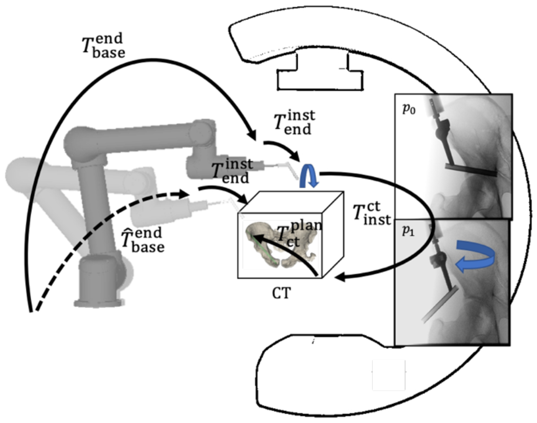
Single-view image-guided robotic positioning. The robot is placed over the patient and radiographs are acquired as the robotically-held instrument rotates over the patient. These radiographs of the patient and robot are used to localize one with respect to the other. The robot is then servoed to a preoperatively planned trajectory by following the transformation tree.
2.2. Calibration-Free Robotic Positioning
Equations (1) and (2) involve a forward projection of the 3D patient preoperative CT and 3D instrument CAD model respectively, in order to generate DRRs for registration. This forward projection is generated using projective geometry of the C-arm that is obtained through a prior, offline geometric calibration of the system. By using this calibration, Equations (1) and (2) optimize the rigid parameters (6 degrees of freedom [DoF]) that describe the pose of the patient preoperative CT and instrument CAD model (respectively). However, to calibrate the system, the C-arm must be encoded and repeatable in its motion profile – the gantry should not flex or bend at different C-arm poses in an inconsistent fashion.
When such a C-arm is not available, a novel method has been developed to extend the usability of image-guided robotic positioning for non-encoded C-arms or C-arms that cannot be calibrated. The method first performs an online calibration of the C-arm from a single radiograph of the patient, giving the C-arm projective geometry in relation to the patient. The projective geometry can be described in the form of a projection matrix PM,10 which can be decomposed in terms of the 9 DoF describing the source position (Ts = [Ts,x, Ts,y, Ts,z]T), detector position (Td = [Td,x, Td,y, Td,z]T), and detector rotation (Rd = [Rd,x, Rd,y, Rd,z]T) as illustrated in Figure 2.
Figure 2.
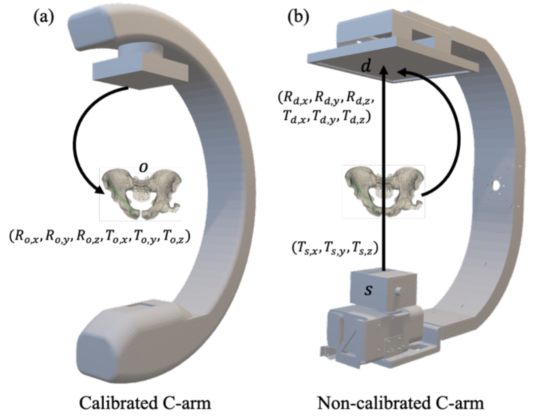
Illustration of geometry and transforms for (a) calibrated and (b) calibration-free systems. (A) Calibrated registration, which solves for the rigid parameters (6 DOF) of the object o (e.g., patient preoperative CT) with respect to the calibrated C-arm imaging system. (B) Calibration-free registration, which solves for the intrinsic (Ts) and extrinsic (Td, Rd) parameters of the C-arm.
The projection matrix PM is composed of an intrinsic matrix PMint that describes the source position, and extrinsic matrix PMext that describes the detector position:
| (4a) |
| (4b) |
| (4c) |
To solve for the calibrated projection matrix , the following function is optimized:
| (5) |
where is an initial volume transform for the patient preoperative CT. After is calculated, the pose of the patient with respect to the C-arm can be calculated as:
| (6) |
where is the initial extrinsic matrix used during the optimization of Equation (5). To solve for the robot registration, Equation (2) is used with the obtained calibration PM.
2.3. Preclinical Evaluation of Drill Guide Alignment
The Cios Spin 3D C-arm (Siemens Healthineers, Erlangen, Germany) was used for experiments involving image-guided robotic positioning. The system has an isocentric gantry and is capable of acquiring 3D CBCT reconstructions for ground truth pose definition of delivered instruments, but for calibration-free registration, the encoders and system calibration were not used. Experiments used a UR5 general purpose robot (Universal Robots, Odense, Denmark) as a general platform for preclinical studies, offering a 6 DoF manipulator with a maximum payload of 5 kg, consisting of a base, shoulder, elbow, and 3 wrist joints. The instrument used in the studies was a standard surgical drill guide through which guidewires and screws can be delivered.
2.3.1. Data Collection
A cadaver torso was used to assess the workflow and performance of the system in a realistic operating setting. Six preoperative fixation plans (and their associated bone corridors) were designated in the preoperative CT of the pelvis. For each planned trajectory, the cadaver was positioned such that the entry point of the trajectory was approximately at isocenter and the robot was positioned over the patient in the FOV. A cone-beam CT (CBCT) containing 400 projections was acquired at 0.3 mAs/projection for the purposes of ground-truth localization of the patient and robot. Additionally, five fluoroscopy images were acquired at 0.3 mAs, with 5 rotations of the robot end effector at 30° increments, providing images for robot registration as well as calibration-free registration. For each workflow, patient and robot registration was performed using the acquired data and used to drive the robot according to Equation (3). After driving, a CBCT of the aligned drill guide was acquired for ground-truth definition.
2.3.2. Outcome Metrics
For each trajectory, ground-truth for patient pose was defined from 3D-2D registrations of CT to a large number of projections from the projection datasets. Registration error was estimated by calculating the difference from ground truth.
| (7) |
To evaluate the geometric accuracy of drill guide alignment, each CBCT of the aligned drill guide was registered to the patient preoperative CT. Two points were manually designated to delineate the trajectory of the drill guide in CBCT (as shown in Figure 3) and its intersection with the cortical bone, surface. This point was defined as (t1) and the trajectory plan entry point was defined as (p0) and this delineated trajectory was defined as xt, and entry point error was defined as:
| (8) |
Figure 3.
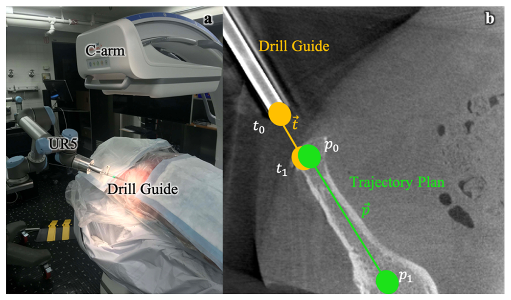
Pre-clinical testing of calibration-free, image-guided robotic positioning. (a) Preclinical system for image-guided robotic positioning of a drill guide. (b) Calculation of outcome metrics from post-driving CBCT of aligned drill guide.
The angular deviation ϵθ between the unit vector trajectory axis and unit vector planned trajectory axis was evaluated as:
| (9) |
Additionally, each delineated trajectory was extrapolated through a surface mesh representation of the patient pelvis, and the distance of the extrapolated trajectory to the cortical bone surface at discrete points along the trajectory was evaluated to determine whether a K-wire delivered through the aligned drill guide would breach the cortex.
III. RESULTS
3.1. Geometric Accuracy of Instrument Alignment
The geometric accuracy of drill guide alignment was evaluated by determining the patient and robot registration errors, followed by the tip point and axis alignment error of the drill guide. Figure 4a shows the patient registration and robot registration errors δx for all trajectories. The results demonstrated the accuracy of registering a robot and patient with no prior calibration of the C-arm compared to a calibrated approach, with patient registration error of 1.2 ± 0.2 mm for the calibration-free approach compared to 0.7 ± 0.2 mm for the calibrated approach, and robot registration of 1.2 ± 0.5 mm compared to 1.0 ± 0.71 mm. The accuracy of drill guide alignment was evaluated for the calibrated C-arm approach and calibration-free C-arm approach, as seen in Figures 4b and 4c. Drill guide tip and axis alignment error for the calibration-free approach was 1.8 ± 0.8 mm and 0.7 ± 0.2°, compared to 1.4 ± 0.7 mm and 0.5 ± 0.3° for the calibrated approach. Both methods achieve average drill guide tip error < 2 mm and axis alignment error < 1°.
Figure 4.
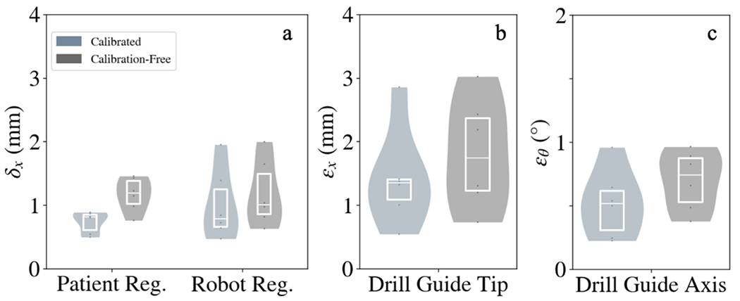
Geometric accuracy of robotic positioning with and without C-arm calibration. (A) Patient and robot registration accuracy for the calibrated and calibration-free approaches. (B,C) Drill guide tip and axis alignment error for both approaches.
Figure 4 shows that while there are marginal increases in error for patient registration, robot registration, and drill guide alignment, all errors remained low (< 2 mm and 1°). The modest increases in error can be attributed to the fact that the calibration-free approach is designed for simple, non-encoded C-arms, and performs an online calibration for such a system using the patient as a calibration object (cf. a more extensive calibration method such as Cho calibration13 involving a calibration-specific phantom). It is likely that resulting calibration therefore has more error, and patient and robot registration errors will be higher and this error will propagate into the drill guide tip and drill guide axis alignment.
3.2. Conformance of Aligned Instrument Trajectory Within Bone
Figure 5 shows that for all 6 trajectories, a simulated K-wire extrapolated from the aligned drill guide did not breach the pelvis, confirming the performance of the calibration-free approach compared to the calibrated approach. The results suggest that despite the marginal increases in registration and drill guide placement error when using the calibration-free approach, these errors do not cause clinically significant breach of the cortical bone.
Figure 5.
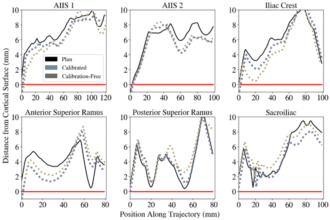
Distance of simulated K-wires from the cortical bone surface. A K-wire mesh model was propagated along the aligned drill guide and the distance of the K-wire mesh model to a mesh model of the cadaver pelvis was evaluated at discrete positions along the length of the K-wire model. Values below the red line (y=0) indicate breaches of the simulated K-wire out of the cortical bone. Positive values indicate conformance of the simulated K-wire within the bone corridor. Six trajectories with various approaches in the pelvis were planned and executed. The black curve shows the preoperative trajectory plan and its distance to the cortical bone surface along the length of the trajectory. The light blue curve shows the calibrated workflow and its cortical bone distance, while the gray curve shows the calibration-free workflow.
IV. DISCUSSION AND CONCLUSIONS
The experiments performed in this work assessed the accuracy of image-guided robotic positioning in a cadaver specimen while assuming no prior calibration of the C-arm, achieving 3D guidance by first calibrating the system via a registration of patient anatomy and then registering the robot using the obtained projective geometry. This approach facilitates use of commonly used C-arms that cannot maintain a prior offline geometric calibration to register the robot to the patient. The results demonstrated that this approach can accurately align a robotic drill guide to target trajectory plans in realistic preclinical setting in cadaver, achieving drill guide tip error and axis alignment error of 1.8 ± 0.8 mm and 0.7 ± 0.2°. Current work on robot pose and path planning are also being implemented to avoid collision of the drill guide with the patient or OR equipment. This work establishes essential preclinical validation, with future work prior to clinical translation involving a cohort of residents and orthopaedic surgeons to more fully establish the safety of the system, obtain user feedback on interaction with the surgical interface, and measure effects that impact workflow, such as radiation dose and runtime.
ACKNOWLEDGEMENT
This work was supported by NIH grant R01-EB-017226 and research collaboration with Siemens Healthineers.
REFERENCES
- 1.Gras Florian, et al. “2D-Fluoroscopic Navigated Percutaneous Screw Fixation of Pelvic Ring Injuries - a Case Series.” BMC Musculoskeletal Disorders, vol. 11, no. 1, 2010, doi: 10.1186/1471-2474-11-153. [DOI] [PMC free article] [PubMed] [Google Scholar]
- 2.Miranda Marta Oñate, and Moser Thomas P.. “A Practical Guide for Planning Pelvic Bone Percutaneous Interventions (Biopsy, Tumour Ablation and Cementoplasty).” Insights into Imaging, vol. 9, no. 3, 2018, pp. 275–285., doi: 10.1007/s13244-018-0600-y. [DOI] [PMC free article] [PubMed] [Google Scholar]
- 3.Jiang Bowen, et al. “Pedicle Screw Accuracy Assessment in ExcelsiusGPS® Robotic Spine Surgery: Evaluation of Deviation from Pre-Planned Trajectory.” Chinese Neurosurgical Journal, vol. 4, no. 1, 2018, doi: 10.1186/s41016-018-0131-x. [DOI] [PMC free article] [PubMed] [Google Scholar]
- 4.Yi Thomas, et al. “Robotic Drill Guide Positioning Using Known-Component 3D–2D Image Registration.” Journal of Medical Imaging, vol. 5, no. 02, 2018, p. 1., doi: 10.1117/l.jmi.5.2.021212. [DOI] [PMC free article] [PubMed] [Google Scholar]
- 5.Ahmed A. Karim, et al. “First Spine Surgery Utilizing Real-Time Image-Guided Robotic Assistance.” Computer Assisted Surgery, vol. 24, no. 1, 2019, pp. 13–17., doi: 10.1080/24699322.2018.1542029. [DOI] [PubMed] [Google Scholar]
- 6.Rubash Harry E. The Adult Knee: Knee Arthroplasty. Wolters Kluwer, 2021. [Google Scholar]
- 7.Brandmeir Nicholas J., et al. “The Comparative Accuracy of the ROSA Stereotactic Robot across a Wide Range of Clinical Applications and Registration Techniques.” Journal of Robotic Surgery, vol. 12, no. 1, 2017, pp. 157–163., doi: 10.1007/s11701-017-0712-2. [DOI] [PubMed] [Google Scholar]
- 8.Comparetti Mirko Daniele, et al. “Optically Tracked Multi-Robot System for Keyhole Neurosurgery.” 2011 IEEE International Conference on Robotics and Automation, 2011, doi: 10.1109/icra.2011.5980057. [DOI] [Google Scholar]
- 9.Vijayan Rohan C., et al. “Image-Guided Robotic k-Wire Placement for Orthopaedic Trauma Surgery.” Medical Imaging 2020: Image-Guided Procedures, Robotic Interventions, and Modeling, 2020, doi: 10.1117/12.2549713. [DOI] [PMC free article] [PubMed] [Google Scholar]
- 10.Ouadah S, et al. “Self-Calibration of Cone-Beam CT Geometry Using 3D–2D Image Registration.” Physics in Medicine and Biology, vol. 61, no. 7, 2016, pp. 2613–2632., doi: 10.1088/0031-9155/61/7/2613. [DOI] [PMC free article] [PubMed] [Google Scholar]
- 11.Silva T De, et al. “3D–2D Image Registration for Target Localization in Spine Surgery: Investigation of Similarity Metrics Providing Robustness to Content Mismatch.” Physics in Medicine and Biology, vol. 61, no. 8, 2016, pp. 3009–3025., doi: 10.1088/0031-9155/61/8/3009.. [DOI] [PMC free article] [PubMed] [Google Scholar]
- 12.Uneri A, et al. “Intraoperative Evaluation of Device Placement in Spine Surgery Using Known-Component 3D–2D Image Registration.” Physics in Medicine and Biology, vol. 62, no. 8, 2017, pp. 3330–3351., doi: 10.1088/1361-6560/aa62c5. [DOI] [PMC free article] [PubMed] [Google Scholar]
- 13.Cho Youngbin, et al. “Accurate Technique for Complete Geometric Calibration of Cone-Beam Computed Tomography Systems.” Medical Physics, vol. 32, no. 4, 2005, pp. 968–983., doi: 10.1118/1.1869652. [DOI] [PubMed] [Google Scholar]


