Abstract
Tissue engineering, whose aim is to repair or replace damaged tissues by combining the principle of biomaterials and cell transplantation, is one of the most important and interdisciplinary fields of regenerative medicine. Despite remarkable progress, there are still some limitations in the tissue engineering field, among which designing and manufacturing suitable scaffolds. With the advent of additive manufacturing (AM), a breakthrough happened in the production of complex geometries. In this vein, AM has enhanced the field of bioprinting in generating biomimicking organs or artificial tissues possessing the required porous graded structure. In this study, triply periodic minimal surface structures, suitable to manufacture scaffolds mimicking bone’s heterogeneous nature, have been studied experimentally and numerically; the influence of the printing direction and printing material has been investigated. Various multi-morphology scaffolds, including gyroid, diamond, and I-graph and wrapped package graph (I-WP), with different transitional zone, have been three-dimensional (3D) printed and tested under compression. Further, a micro-computed tomography (μCT) analysis has been employed to obtain the real geometry of printed scaffolds. Finite element analyses have been also performed and compared with experimental results. Finally, the scaffolds’ behavior under complex loading has been investigated based on the combination of μCT and finite element modeling.
Keywords: Bone scaffolds, Minimal Surface lattices, Additive manufacturing, Multi-morphology, Finite element modeling
1. Introduction
Tissue engineering is a multidisciplinary field that develops the improvement, restoration, or maintenance of natural tissues that have been either damaged or deteriorated[1-3]. The main tissues and organs that have been under the focus of researchers include bone, cartilage, skin, blood vessels, muscle, etc.[4-7]. One method for creating artificial tissues is using additive manufacturing (AM), that is, bioprinting. The realm of bioprinting is divided into three areas: Biomimicry, autonomous self-assembly, and mini-tissue[8]. Among these, one important field in biomimicry is focused on scaffolds on which the tissue is going to be built[9]. To focus more on bone tissue engineering, there have been a variety of problems that are mainly stemmed from the difficulty of repeating the structure and function of the hosting bone[10]. Researches have strikingly progressed in the field of bone tissue engineering during the last decades due to some advances in the manufacturing process.
AM has introduced a novel way of production from different perspectives. It has facilitated the manufacturing of complex geometries with the minimum waste material[11]. The first efforts toward implementing AM-based production return back to the 1980s when researchers used this method to create prototypes[12]. With the advent of other technologies, the true potential of this method got revealed[13-15]. Combining AM with computational methods, researchers can optimize the time, cost, and energy of production[16-20]. A compelling area of using three-dimensional (3D) printing is generating biomimicking organs or artificial tissues. For instance, the AM scaffold tissues can bear considerable loads while they are efficiently lightweight[21-24]. Mimicking the hosting cell heterogeneity is the main advantage of creating artificial tissues using AM[25]. Bone is a stiff tissue having heterogeneous morphology that can be replicated by printed lattice structures with complex geometry. Therefore, fabricating novel porous structures for bone tissue engineering, allowing patient-specific design, have been taken into consideration by researchers[26-28]. For example, Farina et al. 3D printed and evaluated a glass scaffold and provided a micro-computed tomography (μCT)-based finite element modeling (FEM) to investigate the mechanical properties of scaffolds[29]. In another study, Askari et al. fabricated 3D zirconia scaffolds for bone tissue engineering applications and provided a μCT-based FEM for simulation[30].
Designing bone scaffolds based on a mathematical algorithm, one of the latest design methods, has led researchers to use triply periodic minimal surface (TPMS) structures[31-35]. The first TPMS surfaces were initially described and introduced by Hermann Schwarz in 1865[36]. TPMS-based bone scaffolds have some advantages, such as excellent nutrient transportation, oxygen diffusion, and ion exchange, making them a good option for tissue engineering[37-39]. TPMS structures are geometrically complex so that it is somehow impossible to produce such precise geometries with standard manufacturing processes. However, using AM, these fascinating structures can be effortlessly produced. TPMS structures are novel mathematical geometries that can be utilized in several areas, including heat exchangers, body implants, and lightweight structures[40-45]. Their applications in bioengineering have provided researchers with novel solutions to prevailing problems in creating biomimicking tissues and organs. For example, Song et al. designed and analyzed the route analog dental implant based on TPMS structures and compared it with the traditional implant[44]. To mimic the topology of natural tissues, three main grading can be considered, namely, variations in density, cell size, and the lattice type[46]. Accordingly, several surface formulae, each of which defines a unique structure for the TPMS lattice, have been introduced. Schoen-Gyroid, Schwarz-Diamond, and Primitive are among the most famous TPMS structures. Based on the scaffold’s specific mechanical behavior and biological applications, a combination of these structures, consisting of one or more lattice types, can be efficient in biomechanical terms[47,48]. Restrepo et al. used three different 3D-printed ceramic patterns and evaluated their mechanical properties for bone tissue engineering[49]. Liao et al. printed radial gradient TPMS structures for bone tissue engineering and evaluated their mechanical behavior under compressive test. In another study, using the SLM printing method, multi-morphology scaffolds were printed, and their mechanical response was investigated by compression tests[50]. In this vein, a sound comprehension of the role played by transitional zone (TZ) in multi-morphological scaffolds in terms of mechanical behavior is crucial for the development of suitable structures.
Mimicking the hosting cell heterogeneity of bone using lattice structures is the main advantage of creating artificial tissues using AM. A promising group of novel lattice structures used in bone scaffolds is the so-called TPMS structures which are function-based structures. TPMS structures can be readily produced using AM since they are easily defined using mathematical equations, and a combination of different TPMS structures can satisfy mechanical and biological requirements[51]. Therefore, they are good candidates to design and manufacture scaffolds that can mimic bone’s heterogeneous nature. However, different patterns joined together by a transition zone cell structure, cannot be arranged alongside one another without effects on the arising mechanical response; the adopted transition zone is particularly important in terms of mechanical properties. In this perspective, in this study, various multi-morphology scaffolds have been printed by employing fused deposition modeling (FDM) printing method and using different cell types, including gyroid, diamond, and I-graph and wrapped package graph (I-WP).
Literature review shows that researchers have not adequately considered the comprehensive study of multi-morphology scaffolds. Furthermore, in this study, the mechanical properties of printed multi-morphology scaffolds with different TZ under compression tests have been evaluated, and FEM analyses have been used to validate experimental results. Since the elastic response of scaffolds under mechanical loads is the fundamental aspect to be considered in biomechanical applications, the behavior of printed scaffolds within the linear elastic regime has been investigated experimentally and numerically. Moreover, experimental compression tests have been conducted to study other effects, including cell type, printing direction, and material variation. In addition, since the FDM AM technology process results in printing anomalies and imperfections, a μCT analysis has been used to evaluate the printing quality and to obtain the real geometry of printed scaffolds. Moreover, the effect of printing direction, cell type, and filament variation has been investigated. A crucial challenge in the field of biomechanics is the difficulty in conducting different mechanical tests. To be more specific, seldom a multi-morphology specimen can be designed with an appropriate fixture for experimental tests. To quantify the mechanical response of printed bone scaffolds under different loadings, a method based on the combination of μCT and FEM has been used in this study.
2. Methods and fabrication
Different steps have been considered to tackle the problem of obtaining multi-morphology scaffolds with controlled characteristics. The flowchart adopted in the present study is illustrated in Figure 1. In each section of the paper, the details related to the various aspects will be provided accordingly.
Figure 1.
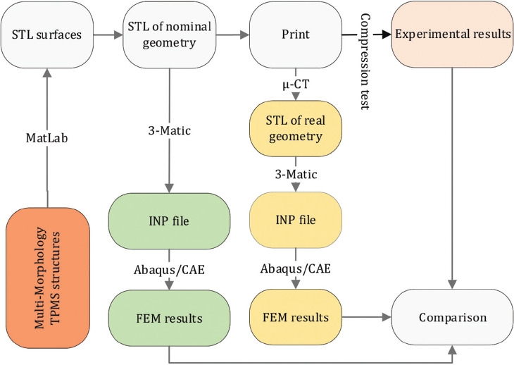
Flowchart of the steps adopted in this study.

2.1. Geometrical design of scaffolds
Multi-morphology structures made from TPMS have been widely used in biomechanical scaffolds[37,52,53]. Their geometries have different functions since the lattice structure change in terms of porosity, cellular topology, and the material itself[54,55]. As described in the previous sections, bone tissue structures vary locally. A typical knee joint is illustrated in Figure 2. To properly mimic the real geometry of natural bone and cartilage tissues in the knee joint, scaffolds made of regions with different structures, each one suitable for hosting the tissues that are created during healing, must be defined.
Figure 2.
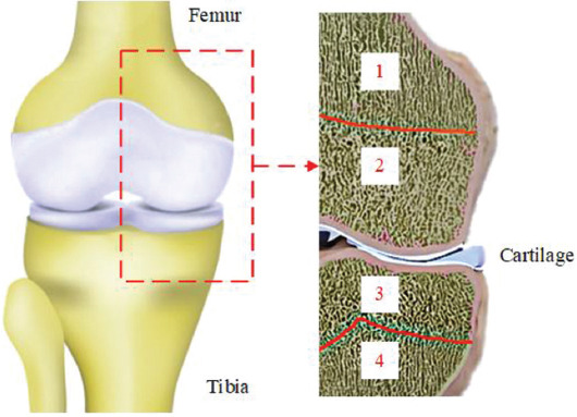
Scheme of different tissues present in a knee joint: Different bone morphology zones: 1-4.
In this work, TPMS structures have been defined using unit cell design based on mathematical equations[56]. These structures are designed so that they have the minimum surface, that is, the mean curvature is locally zero. Each one of these surfaces has a specific equation in 3D space. Figure 3 shows three common TPMS structures whose mathematical definition is provided by the following equations:
Figure 3.
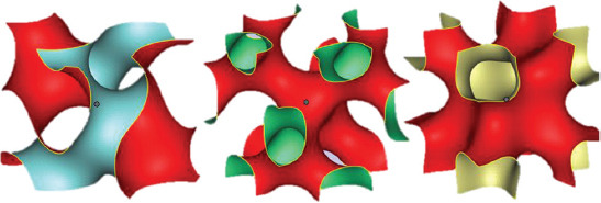
Images of three common TPMS structures: Gyroid, diamond, and Schoen I-WP (from left to right).
Where, d represents the characteristic size of the unit cell of each structure and t defines the porosity of the whole cellular structure such that larger values of t lead to denser cells. For this study, the value of t was chosen 0.3 so that the resulting porosity complies with the limits of polymeric scaffolds[57,58]. Assuming d/2π=1, which leads to the unit cell size of d=6.28 mm, the following equations for the TPMS structures used in this paper can be obtained:
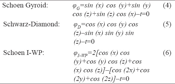
To obtain a multi-morphology structure, the following function is defined:

Where, φMML is the multi-morphology surface equation for the lattice structure, assumed to be made of two specific lattice types: φG and φD. In this work, φG and φD represent Schoen-Gyroid and Schwarz-Diamond TPMS structures, respectively. Furthermore, γ is the transitional function defining the structure transition from φG to φD; its expression is as follows:

According to the value of the constant K≥0, the multi-morphology scaffold can change its structure either suddenly or gradually; the influence of its value on the resulting TPMS has been studied in this work. Moreover, since the function (8) depends only on the spatial coordinate x, the function φMML defines a structure that changes from φG to φD along the x coordinate. Further variation in lattice type can be achieved by relating this function to the other coordinates.
2.2. 3D printing of TPMS scaffolds
The dimension of the TPMS structure domain, created using MATLAB® software, is 40×20×20 mm3. The cellular type has been assumed to vary along the axis that represents the longest edge of the domain. After creating the mesh with the proper size, the obtained geometry has been exported in Standard Tessellation Language (STL) format. To create a volumetric STL file, the created surfaces have been specified to have thickness value equal to 0.5 mm. Afterward, the CAD files have been printed with FDM 3D printing (3DPL Co. Ltd.) using two types of PLA filaments with different mechanical properties (Figure 1). The printing parameters are reported in Table 1.
Table 1.
3D printing parameters used in the FDM printing technology
| Material | Melting temperature (°C) | Layer height (µm) | Printing speed (mm/s) | Bed temperature (°C) |
|---|---|---|---|---|
| PLA 1 | 190 | 50 | 10 | 24 |
| PLA 2 | 215 | 50 | 10 | 24 |
2.3. Finite element modeling
An FEM has been implemented for simulating numerically the compression test. A major problem in importing the STL file into Abaqus/CAE FEM package consisted in the lack of volume of the generated STL surface file. To convert the surface geometry to a solid mesh, 3-Matic Medical software was used. Mesh refinement algorithms were applied to obtain linear tetrahedral elements with a suitable edge ratio. Finally, the mesh was exported as an orphan mesh to Abaqus (Figure 1). The free-body diagram of each slice (cross-sections perpendicular to the height of the scaffold) was determined. The cross-section at the middle of the scaffold, that is, at the middle of the TZ, was selected for comparison; the reaction force, which was used for obtaining the load-displacement curves, is determined from this step.
To determine the mechanical behavior of the adopted polymers, compression tests have been performed on 3D-printed samples made of two different polylactic acid (PLA) materials, PLA1 and PLA2; for this purpose, specimens with dimensions 40×20×20 mm3 have been used. The compression test provided the bulk material properties used in numerical simulations; in particular, Young’s modulus and Poisson’s ratio of the PLA1 and PLA2 materials have been obtained to be E1=930 MPa, ν1=0.4 and E2=550 MPa, ν2=0.4, respectively.
2.4. μCT
It is difficult when the simulation of an object with a complex geometry is required, especially when their CAD model cannot be obtained from exact mathematical equations. For instance, natural structures, including bone tissues, rock specimens, and leaves, are challenging to model. μCT facilitates modeling these natural structures by allowing to capture their microscale details. Another application of this technology is to evaluate the printing accuracy of AM objects. In this context, two 3D-printed scaffold structures were scanned to study the printing accuracy achieved. The scan files provided details about the micropores between the deposited layers and extra fused materials at the edges of the scaffolds. Figure 4 illustrates one scanned specimen and its comparison with its nominal (i.e., mathematically exact) geometry. According to Figure 4, the printed samples have many anomalies which can affect the mechanical behavior of the whole scaffold. For example, the unintentional accumulation of the materials on the sharp edges, which is inevitable when using FDM, can increase the strength of the scaffold and lower the stress concentration in the mentioned regions. Hereafter, the scanned specimens will be labeled as real specimens while the designed ones will be termed as nominal specimens.
Figure 4.
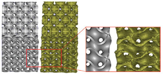
Comparison of nominal (left) and real (right) designed bone scaffolds.
A desktop μCT scanner, equipped with a cone-beam micro-focus X-ray source and a flat panel detector, was used in this study (LOTUS-NDT, Behin Negareh Co.). In scanning the samples, the X-ray tube voltage and its current were set to 60 kV and 50 μA, respectively. The total scan time for each sample was ~ 2.5 h, and the obtained resolution was 70 microns.
Micro datasets were analyzed as follows: The images were first converted to BMP format and the so-called median filtering was applied to smooth the 3-D images using a 3×3×3 kernel (in open-source ImageJ software). Then, the image stack was set to a specific threshold using a customized MATLAB® code. The threshold level used for the CT data was defined to give a 99.5% porous structure as calculated from experimental measurements. Voxels of intensity below the threshold were assumed to represent porous regions, whereas those above were assumed to indicate bulk regions. Finally, the porosity was obtained by calculating the number of voxels representing pores and their distribution was calculated using a customized MATLAB® code.
2.5. Mechanical tests
Several mechanical tests were performed to investigate different parameters’ effects on the mechanical response of additively manufactured scaffolds. Moreover, all compression tests were performed with speed of 1 mm/min at room temperature (23°C). As described previously, two different filaments made of pure poly lactic acid (PLA, labeled PLA1) and a PLA reinforced with carbon nano tube (CNT-PLA, labeled PLA2) were used (Figure 5).
Figure 5.
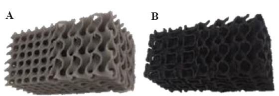
Printed scaffolds obtained using different polymer filaments. (A) PLA (PLA1) and (B) CNT-PLA (PLA2).
In addition, scaffolds were printed in both vertical and horizontal directions to investigate the effect of the printing direction on the mechanical response (Figure 6). Slicing the specimens with a normal vector parallel to the largest dimension results in vertical printing, while using a normal perpendicular to the largest dimension results in horizontal printing.
Figure 6.
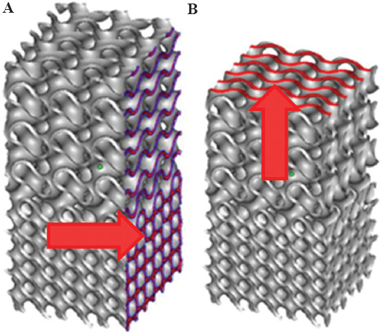
Scheme of the (A) horizontal and (B) vertical 3D printing directions.
Furthermore, TPMS gyroid structures were combined with both I-WP and diamond structures with different degrees of TZ sharpness. When scaffolds made of a combination of gyroid and diamond structures are concerned, different sizes of the TZ have been used. Figure 7A-D shows the nominal geometries for samples with the variation in TZ (specimens 4 – 7 in Table 2), Figure 7E and F illustrates the corresponding printed scaffolds.
Figure 7.
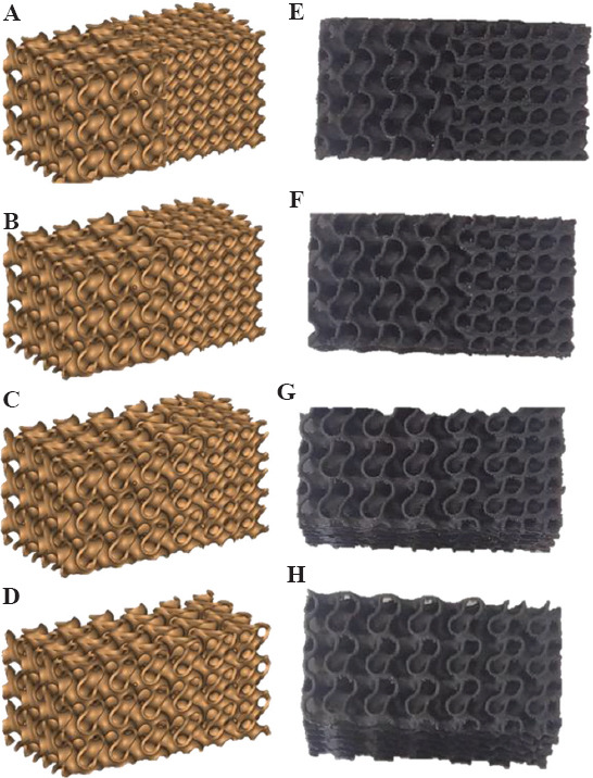
Scaffolds with different transitional zones (left: Nominal geometries; right: 3D printed scaffolds). S4H (A and E), S5H (B and F), S6H (C and G), and S7H (D and H).
Table 2.
Geometrical, printing, and materials characteristics of tested scaffold specimens
| Specimen number | Description | K | Material | Printing direction | µ-CT |
|---|---|---|---|---|---|
| S1H | Gyroid | -- | CNT-PLA | H | |
| S2H | I-WP | -- | CNT-PLA | H | |
| S3H | G+I-WP | 20.00 | CNT-PLA | H | * |
| S4H | G+D | 20.00 | CNT-PLA | H | |
| S5H | G+D | 0.30 | CNT-PLA | H | |
| S6H | G+D | 0.15 | CNT-PLA | H | |
| S7H | G+D | 0.10 | CNT-PLA | H | |
| S8H | Diamond (D) | -- | CNT-PLA | H | |
| S9V | G+I-WP | 20.00 | PLA | V | |
| S10V | G+D | 20.00 | PLA | V | * |
| S11V | G+I-WP | 20.00 | CNT-PLA | V | |
| S12V | G+D | 20.00 | CNT-PLA | V | |
| S13H | G+I-WP | 20.00 | PLA | H | |
| S14H | G+D | 20.00 | PLA | H |
Table 2 describes the details of each considered specimen; in particular, the parameter K defines the transitional zone size: According to Eq. (8), the higher the value of the K, more sudden the transition between cell types would be (Figure 8). Further, the printing material used and the printing direction are also indicated; the last column indicates the specimens used to obtain the μCT scans.
Figure 8.
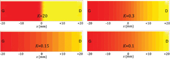
Scheme of the geometric transition between two different cell structures (such as G to D) according to the value of the parameter K.
3. Experimental and numerical results
In this section, the results of experiments and numerical simulations in terms of the mechanical response of 3D printed scaffolds are illustrated and compared. In general, eight different scaffold geometries, whose relative density is reported in Table 3, were created using an in-house code. In addition, in Table 3, the porosity is also reported for μCT specimens.
Table 3.
Porosity of the designed scaffolds.
| Specimen number | Description | Porosity % |
|---|---|---|
| S1H | Gyroid | 75.51 |
| S2H | I-WP | 74.08 |
| S3H | G+I-WP | 74.27 |
| S4H | G+D | 72.25 |
| S5H | G+D | 72.89 |
| S6H | G+D | 73.15 |
| S7H | G+D | 73.37 |
| S8H | Diamond | 69.71 |
| Micro-CT3 | G+I-WP (3) | 73.52 |
| Micro-CT10 | G+D (4) | 71.73 |
3.1. Experimental results
Three cell types, including diamond, gyroid, and I-WP structures, were printed in one direction to see the general response of each structure solely. The size of cells and the wall thickness have been assumed to be the same for all scaffolds. In Figure 9A, the results of the compression test for single-cell scaffolds are presented. According to the load-displacement curve, the diamond structure shows the stiffest response. Despite the cell geometry, the stiffness of the scaffold is mainly related to its porosity (Table 3). This behavior has been stated and proven by Ashby et al.[59]. The higher the porosity, the lower the density of scaffolds and the lower the stiffness would be; a relationship suitable to estimate the Young’s modulus of porous materials has been proposed in the following form.
Figure 9.
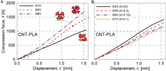
(A) Mechanical response under compression of single-cell scaffolds type: S1H (Gyroid), S2H (I-WP), and S8H (Diamond). (B) Effect of variation of the scaffold TZ on the mechanical response under compression: S4H (K=20, sharpest transition), S5H (K=0.3), S6H (K=0.15), and S7H (K=0.1, smoothest transition).

Where, ρs indicated the density of the reference material with Young’s modulus Es, while ρ and E represent the corresponding quantities of the porous material of interest, namely, the scaffolds. The above relationship does not account for the geometry of the pores, so the scaffolds’ behavior weakly depends on the cell type, while the porosity, that is, the relative density, plays the main role. In addition, according to the curves and the data in Table 3, both I-WP and gyroid structures have approximately the same porosity but different responses. It is worth noticing that lattices are either bending or stretching dominated structures, and I-WP has a stretching-dominated response[56]. This is why the I-WP lattice has a much higher stiffness than the gyroid lattice. Thus, whether the scaffold is a bending or stretching dominated structure define the overall response for scaffolds with the same porosity.
Even though the natural tissues do have different cell sizes and types, the variation between two structures is usually gradual, that is, a smooth transitional zone exists. Because of the graded structure of natural bone tissues, the effect of the degree of variation between two structures (gyroid and diamond) in terms of the mechanical response has been analyzed in the present study. Figure 9B shows the response of a scaffold with different K values. According to the value of the transitional parameter K, the transitional zone varies from a sudden change (K = 20) to a gradual (K = 0.1) change between the two pure structures present at the two extremities of the scaffold; specimen S4H has the sharpest transition zone, while specimen S7H has the most gradual transition between gyroid and diamond structures.
It is worth noticing that an increase in the size of TZ, that is, making the transition in the scaffold more gradual, leads to a less stiff scaffold. This behavior stems from the lower porosity of the gyroid structure. According to Figures 7 and 8, by increasing the TZ’s size, the fraction of gyroid cells is greater than that of diamond ones. As a result, the reduction of stiffness stems from this issue, so the porosity of the scaffolds for multi-morphology structure has more importance than the size of transitional zone.
AM process parameters affect the structural integrity of the printed components because of the local transient heat sources that lead to a heterogeneous material. FDM is not an exception to this general rule. To see the effects of this variation, geometries 3 and 4 in Table 2 were printed using the same filament under the same curing process. The results of the compression test on these samples are presented in Figure 10A and B. Figure 10A illustrates the compressive behavior of both geometries 3 and 4 made of PLA2 using two different printing directions. As it is shown, the horizontal printing leads to a softer scaffold. The main reason behind this is the weak bonding between filaments. To illustrate this notion, the scaffolds were compressed up to 50% of their height. Figure 11 shows the behavior of two similar scaffolds with the same material but different printing direction. Delamination of the deposited layers is the main reason of failure in S4H which has been printed horizontally. On the other hand, the weak bonding between layers has not affected the behavior of vertically printed sample (S12V). Similarly, this mechanism is the governing rule for the small strains so that the vertically printed scaffolds will have stiffer structure. This justification is true only for geometry 4 which is a bending-dominated structure. However, for the stretching-dominated geometry, the printing direction does not show a meaningful trend; the comparison between S3H and S11V does not prove clearly the hypothesis that vertical printing produces stiffer scaffolds.
Figure 10.
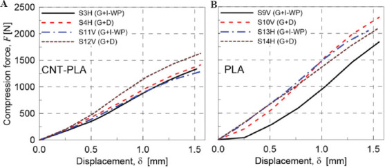
(A) Mechanical response under compression of CNT-PLA specimens: Effect of the printing direction variation, H and V, for the sharpest variation of the scaffold structure (K=20). (B) Mechanical response under compression on various scaffolds made of material PLA1: S9V (G+I-WP), S10V (G+D), S13H (G+I-WP), and S14H (G+D).
Figure 11.
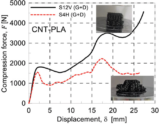
Compressive behavior of two similar scaffolds with different printing directions. S12V (G+D) and S4H (G+D).
To investigate the effect of the filament materials, two different filaments were used for printing the samples. The first reason for using different materials to choose the best possible materials for biodegradable scaffold is achieving different stiffnesses. This mechanical characteristic is crucial when designing a biodegradable scaffold. Due to stress shielding effect, a stiffer material is not always the best option even though its structural integrity would be enhanced. While CNT-PLA material has a different mechanical response than PLA1, it is partially conductive; the electrical conductivity, which is the result of additional CNT, gives electrical functionality to the designed scaffolds and expands the applicability of scaffolds printed using this composite filament. Hence, the aim is to provide a scaffold with different possible functions so that the designer can observe the effect of each factor in the healing process and time. The load-displacement curves of specimens 3 and 4 are reported in Figure 12A and B. Accordingly, the printed PLA1 scaffold showed a stiffer behavior than the corresponding PLA2 one. This will provide a set of tunable mechanical properties for each patient specific scaffold.
Figure 12.
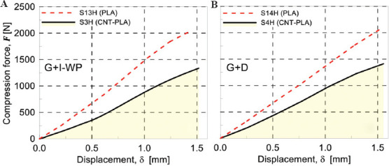
(A) Mechanical response under compression for scaffolds G+I-WP (K=20) made of different materials: S3H (CNT-PLA) and S13H (PLA). (B) Mechanical response under compression for scaffolds G+D (K=20) made of different materials: S4H (CNT-PLA) and S14H (PLA).
3.2. Finite element modeling results
First, mesh convergence study has been performed for one compression test to define the optimum element size. Second, the results of load-displacement curves of the linear part of experiments have been compared with the FEM results to evaluate and verify the accuracy of the FEM. The total force acting on the middle cross-section of the scaffold has been extracted from the output file. The FE model with the highest number of finite elements (around 5.2E+6 elements) has been assumed to provide the reference solution, and the other cases have been compared to it. According to Figure 13, the optimum mesh has been identified to possess around 2,000,000 elements, leading to about 96.97% accuracy.
Figure 13.
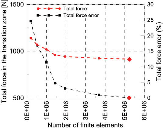
Mesh convergence study: Total force in the transition zone and total force error versus the number of finite elements. The FE reference case is indicated with  .
.
In Figure 14, the FEM results related to the nominal and real geometry have been compared with experimental results in the linear regime for specimen number 3 and 10, in subfigures a and b, respectively. In general, the linear response for both the scaffold’s nominal and real geometry presents a good match with the obtained load-displacement curves determined from compression tests. However, as will be discussed further, the real geometry has led to more accurate results.
Figure 14.
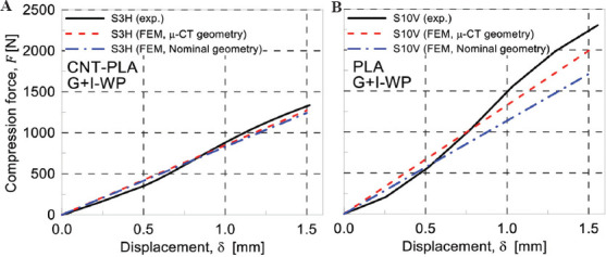
Comparison of finite element modeling and experimental results for specimen S3H (A) and S10V (B).
Two printed scaffolds, S3H and S10V, were chosen for μCT scan. The resolution of the reported STL files was around 25 μ. However, due to the limitation of the computational resources, a re-mesh strategy was adopted so that the final resolution was in the range 80 – 125 μ. Specimens 3 and 10 were scanned using μCT and the corresponding numerical model for the FE simulation was created using solid elements.
The Von Mises stress contours show that scaffolds tend to fail sooner in the gyroid section than in both I-WP and diamond sections. The comparison between I-WP and gyroid is not challenging because the latter is bending dominated while the first one is stretching dominated, meaning that I-WP structure is keen to fail under the buckling mechanism. As a consequence, the I-WP structure fails at a greater load value than the gyroid one. However, the combination of gyroid and diamond structure requires a more detailed explanation because both of them are bending-dominated TPMS structures and the cell size and thickness are the same for each part.
According to Table 3, the porosity of gyroid and diamond structures is 75.51% and 69.71%, respectively. Based on the work of Ashby et al.[59], the more porous the scaffold, the lower the cellular structure’s strength must be. Therefore, apart from any specific geometry and topology of gyroid and diamond structures, since the gyroid is more porous than the diamond, it will fail sooner. FEM model and experiments are in good agreement with this statement. Specimen 10 has such a structure and the FEM Von Mises stress results for both the real and nominal geometry are shown in Figure 15.
Figure 15.
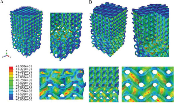
Von Mises stress contours obtained by FEM for specimen S10V by considering its real (A) and nominal (B) geometry.
Based on the obtained stress map, it can be observed that scaffold in the gyroid region is more susceptible to fail than the diamond region. However, the stress contour for the nominal geometry differs from the real specimen in some points. First, the nominal geometry has sharp boundaries which are responsible for stress concentration; on the other hand, in real cases, this does not occur because the material distribution is not sharp being the FDM printing method not so precise to create sharp boundaries. Hence, the predictions based on the real geometry obtained through the μCT scan and lead to more precise results than the nominal scaffolds. In addition, the direction where stress concentration takes place in the middle of the gyroid section is slightly different when the nominal or real geometries are considered. Of course, load-displacement curves obtained for experimental and nominal geometries indicate that the nominal geometry for this specimen shows a 23.49% error in terms of total force while the real geometry shows a 10.70% error. Consequently, the load-displacement curves show approximately 12.79% improvement in the accuracy of the FEM when using μCT.
In Figure 16, the FEM results of real and nominal geometry of scaffold S3H are shown. Red arrows in Figure 16B indicate regions with stress concentration. Therefore, the indicated points are susceptible to fail more likely than other points of the scaffold. However, in the real geometry, there are some useful points to be considered; the gyroid section has stress concentration in the middle while in the nominal geometry, only the sharp edges at the boundaries and at the transitional zone have shown stress concentration. Therefore, each contour predicts that the material starts failing either in the middle of the gyroid section or at its boundaries and transitional zone, respectively. In reality, the designed sharp edges and geometries cannot be accurately printed using FDM method. Consequently, the sharp edges and boundaries do not exist with the edge resolution found in nominal scaffolds, so the real geometry which has been acquired using μCT leads to more valid results than the nominal geometries.
Figure 16.
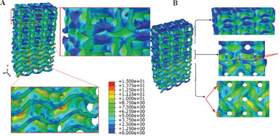
Von Mises stress contours obtained by FEM for specimen S3H by considering its real (A) and nominal (B) geometry.
Another point regarding the stress distribution taking place in the real geometry is that the additional materials that have been melted in the closed-cell structures in the I-WP section have not experienced any stresses due to compression (Figure 16A, top right). This means that the variation in the results is not stemmed from those printing anomalies. Indeed, the variation of the materials deposition in the sharp edges and also in the load-bearing walls of the scaffold is responsible for the difference between the nominal and μCT results.
3.3. Real-world biomechanical application
Multi-morphology scaffolds have diverse applicability in biomechanics. For instance, in regions where the morphology of the hosting bone changes in the knee joint, a scaffold should mimic this natural feature for reaching better results. Approaching that goal is not feasible unless a detailed model is prepared from the multi-morphology area between knee and cartilage. In addition, applying loads on bone scaffolds are not always as simple as a uniaxial compression test. Different loads in different directions may apply to the scaffold. In this regard, a real-world eccentric loading has been simulated on the real geometry of specimen number 3 (Table 2) to provide a better prediction of the mechanical behavior of the scaffold. This kind of loading is always possible for knee joints[60]. For example, when something is being picked up, the direction of the bones are no longer parallel to each other, so the resulting force on the knee joint will be an eccentric force. The stress fields in the scaffold will help the designer to optimize the structural integrity of the component (Figure 17).
Figure 17.
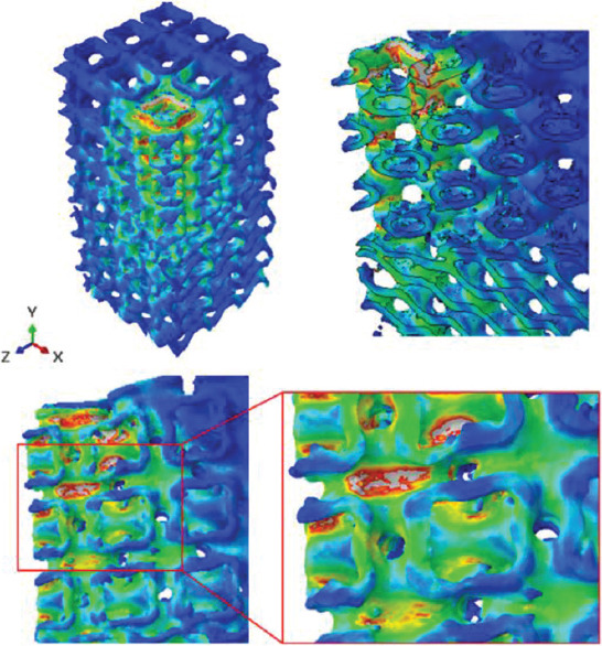
Von Mises stress contours for a complex loading on specimen S3H.
In addition, the interaction between the designed scaffold and live tissues and molecules, which are the foundations of the growth mechanism, can be calculated from the FEM results of μCT scans. Thus, the FEM-μCT simulation is a powerful tool in the hands of the tissue engineer to study the effect of different factors.
4. Conclusions
Different scaffolds with different transition zones were designed and 3D printed by employing the FDM process. First, single-cell type structures, including diamond, I-WP, and gyroid, were designed and printed. It has been shown that the diamond structure was stiffer than others as the porosity plays a significant role on the scaffold’s behavior. The results showed that the effect of the transitional zone is less important than that of the porosity; in other words, the results of compression test revealed that some scaffolds with sudden transitional zones but lower porosity in comparison with other scaffolds had higher Young’s modulus. However, it should be considered that these results are valid only in the compression test; for other mechanical tests, such as shear, tensile, or multi-axial loading, the effects of transition zones could be different. Furthermore, the AM build orientation for bending-dominated scaffolds, including gyroid and diamond, showed that scaffolds printed vertically displayed a stiffer mechanical response with respect to horizontally printed scaffolds. Nevertheless, a meaningful trend could not be extracted for the I-WP cell type that is a stretching-dominated scaffold. Further, μCT analysis was employed to determine the quality of real printed scaffolds. μCT images exhibited that the FDM process does not provide high-quality scaffolds and some geometrical anomalies always exist. The finite element method was finally implemented and verified with the experimental results. It has been shown that the μCT-based FEM method is able to better predict the mechanical behavior of 3D-printed scaffolds rather than using the scaffold’s nominal geometry. Because of the complex nature of the mechanical problem under study, a μCT-FEM approach was used to analyze a case characterized by complex loadings. In conclusion, this study revealed that in multi-morphology scaffolds with sudden or gradual transition zones, the porosity has the dominant effect, that is, the lower the porosity, the stiffer the Young’s modulus.
Acknowledgments
The authors would like to acknowledge Behin Negareh Co., Ltd., Tehran, Iran, for μCT imaging using their LOTUS-NDT scanner, and image processing and analysis services. They also gratefully acknowledge the partial support from European Union’s Horizon 2020 research and innovation program (H2020-WIDESPREAD-2018, SIRAMM) under grant agreement No. 857124.
Conflict of interest
The authors declare that they have no known competing financial interests or personal relationships that could have appeared to influence the work reported in this paper.
Author contributions
Conceptualization, R.N., A.H., and M.B. Data curation, R.N. and F.T. Formal analysis, R.N., F.T., A.Z., R.B., M.A.S., A.R.G., A.H., and M.B. Investigation, R.N. Methodology, R.N., A.H., and M.B. Supervision, A.H. and M.B. Visualization, R.N. and F.T. Writing – original draft, R.N. and F.T. Writing – review and editing, R.N., F.T., A.Z., R.B., M.A.S., A.R.G., A.H., and M.B. All authors have read and agreed to the published version of the manuscript.
References
- 1.Furth ME, Atala A. Principles of Tissue Engineering. Amsterdam, Netherlands: Elsevier; 2014. Tissue Engineering:Future Perspectives; pp. 83–123. [Google Scholar]
- 2.McClelland R, et al. Tissue Engineering. In: Enderle JD, Blanchard SM, Bronzino JD, editors. Introduction to Biomedical Engineering. 2nd0ed. Boston: Academic Press; 2005. pp. 313–402. [Google Scholar]
- 3.Rumpler M, Woesz A, Dunlop JW, et al. The Effect of Geometry on Three-dimensional Tissue Growth. J R Soc Interface. 2008;5:1173–80. doi: 10.1098/rsif.2008.0064. [DOI] [PMC free article] [PubMed] [Google Scholar]
- 4.Koons GL, Diba M, Mikos AG. Materials Design for Bone-tissue Engineering. Nat Rev Mater. 2020;5:584–603. [Google Scholar]
- 5.Whitney GA, Jayaraman K, Dennis JE, et al. Scaffold-free Cartilage Subjected to Frictional Shear Stress Demonstrates Damage by Cracking and Surface Peeling. J Tissue Eng Regen Med. 2017;11:412–24. doi: 10.1002/term.1925. [DOI] [PMC free article] [PubMed] [Google Scholar]
- 6.Saveleva M, Ivanov AN, Chibrikova JA, et al. Osteogenic Capability of Vaterite-Coated Nonwoven Polycaprolactone Scaffolds for In Vivo Bone Tissue Regeneration. Macromol Biosci. 2021;21:e2100266. doi: 10.1002/mabi.202100266. [DOI] [PubMed] [Google Scholar]
- 7.Boyce ST, Lalley AL. Tissue Engineering of Skin and Regenerative Medicine for Wound Care. Burns Trauma. 2018;6:4. doi: 10.1186/s41038-017-0103-y. [DOI] [PMC free article] [PubMed] [Google Scholar]
- 8.Murphy SV, Atala A. 3D Bioprinting of Tissues and Organs. Nat Biotechnol. 2014;32:773–85. doi: 10.1038/nbt.2958. [DOI] [PubMed] [Google Scholar]
- 9.Yang Y, Wang G, Liang H, et al. Additive Manufacturing of Bone scaffolds. Int J Bioprint. 2019;5:148. doi: 10.18063/IJB.v5i1.148. [DOI] [PMC free article] [PubMed] [Google Scholar]
- 10.Leong K, Chua CK, Sudarmadji N, et al. Engineering Functionally Graded Tissue Engineering Scaffolds. J Mech Behav Biomed Mater. 2008;1:140–52. doi: 10.1016/j.jmbbm.2007.11.002. [DOI] [PubMed] [Google Scholar]
- 11.Lv Y, Wang B, Liu G, et al. Metal Material, Properties and Design Methods of Porous Biomedical Scaffolds for Additive Manufacturing:A Review. Front Bioeng Biotechnol. 2021;9:194. doi: 10.3389/fbioe.2021.641130. [DOI] [PMC free article] [PubMed] [Google Scholar]
- 12.Wong KV, Hernandez A. A Review of Additive Manufacturing. Int Sch Res Notices. 2012;2012:208760. [Google Scholar]
- 13.Rezaei R, Ravari MR, Badrossamay M, et al. Mechanical Characterization and Finite Element Modeling of Polylactic Acid BCC-Z Cellular Lattice Structures Fabricated by Fused Deposition Modeling. Proc Inst Mech Eng Part C. 2017;231:1995–2004. [Google Scholar]
- 14.Schaedler TA, Carter WB. Architected Cellular Materials. Ann Rev Mater Res. 2016;46:187–210. [Google Scholar]
- 15.Brighenti R, Cosma MP, Marsavina L, et al. Laser-based Additively Manufactured Polymers:A Review on Processes and Mechanical Models. J Mater Sci. 2021;56:961–98. [Google Scholar]
- 16.Moshki A, Hajighasemi MR, Atai AA, et al. Optimal Design of 3D Architected Porous/Nonporous Microstructures of Multifunctional Multiphase Composites for Maximized Thermomechanical Properties. Comput Mech. 2022;69:979–96. [Google Scholar]
- 17.Jebellat E, Baniassadi M, Moshki A, et al. Numerical Investigation of Smart Auxetic Three-dimensional Meta-structures Based on Shape Memory Polymers Via Topology Optimization. J Intell Mater Syst Struct. 2020;31:1838–52. [Google Scholar]
- 18.Noroozi R, Bodaghi M, Jafari H, et al. Shape-adaptive Metastructures with Variable Bandgap Regions by 4D Printing. Polymers. 2020;12:519. doi: 10.3390/polym12030519. [DOI] [PMC free article] [PubMed] [Google Scholar]
- 19.Soltani A, Noroozi R, Bodaghi M, et al. 3D Printing on-water Sports Boards with Bio-inspired Core Designs. Polymers. 2020;12:250. doi: 10.3390/polym12010250. [DOI] [PMC free article] [PubMed] [Google Scholar]
- 20.Bodaghi M, Noroozi R, Zolfagharian A, et al. 4D Printing Self-morphing Structures. Materials. 2019;12:1353. doi: 10.3390/ma12081353. [DOI] [PMC free article] [PubMed] [Google Scholar]
- 21.Knight A. Cancer Patient Receives 3D Printed Ribs in Worldfirst Surgery 2015 [Google Scholar]
- 22.Ali D, Ozalp M, Blanquer SB, et al. Permeability and Fluid Flow-induced Wall Shear Stress in Bone Scaffolds with TPMS and Lattice Architectures:A CFD Analysis. Eur J Mech B Fluids. 2020;79:376–85. [Google Scholar]
- 23.Jiang H, Aihemaiti P, Aiyiti W, et al. Study Of the Compression Behaviours of 3D-printed PEEK/CFR-PEEK Sandwich Composite Structures. Virtual Phys Prototyp. 2021;2021:138–55. [Google Scholar]
- 24.Meng Z, He J, Li D. Additive Manufacturing and Large Deformation Responses of Highly-porous Polycaprolactone Scaffolds with Helical Architectures for Breast Tissue Engineering. Virtual Phys Prototyp. 2021;16:291–305. [Google Scholar]
- 25.Zhang XY, Fang G, Zhou J. Additively Manufactured Scaffolds for Bone Tissue Engineering and the Prediction of their Mechanical Behavior:A Review. Materials. 2017;10:50. doi: 10.3390/ma10010050. [DOI] [PMC free article] [PubMed] [Google Scholar]
- 26.Yang J, Gao H, Zhang D, et al. Static Compressive Behavior and Material Failure Mechanism of Trabecular Tantalum Scaffolds Fabricated by Laser Powder Bed Fusion-based Additive Manufacturing. Int J Bioprint. 2022;8:438. doi: 10.18063/ijb.v8i1.438. [DOI] [PMC free article] [PubMed] [Google Scholar]
- 27.Aihemaiti P, Jiang H, Aiyiti W, et al. Optimization of 3D Printing Parameters of Biodegradable Polylactic Acid/Hydroxyapatite Composite Bone Plates. Int J Bioprint. 2022;8:490. doi: 10.18063/ijb.v8i1.490. [DOI] [PMC free article] [PubMed] [Google Scholar]
- 28.Chao L, Jiao C, Liang H, et al. Analysis of Mechanical Properties and Permeability of Trabecular-Like Porous Scaffold by Additive Manufacturing. Front Bioeng Biotechnol. 2021;9:779854. doi: 10.3389/fbioe.2021.779854. [DOI] [PMC free article] [PubMed] [Google Scholar]
- 29.Farina E, Gastaldi D, Baino F, et al. Micro Computed Tomography Based Finite Element Models for Elastic and Strength Properties of 3D Printed Glass Scaffolds. Acta Mech Sinica. 2021;37:292–306. [Google Scholar]
- 30.Askari E, Cengiz IF, Alves JL, et al. Micro-CT Based Finite Element Modelling and Experimental Characterization of the Compressive Mechanical Properties of 3-D Zirconia Scaffolds for Bone Tissue Engineering. J Mech Behav Biomed Mater. 2020;102:103516. doi: 10.1016/j.jmbbm.2019.103516. [DOI] [PubMed] [Google Scholar]
- 31.Castro A, Ruben RB, Gonçalves SB, et al. Numerical and Experimental Evaluation of TPMS Gyroid Scaffolds for Bone Tissue Engineering. Comput Methods Biomech Biomed Eng. 2019;22:567–73. doi: 10.1080/10255842.2019.1569638. [DOI] [PubMed] [Google Scholar]
- 32.Castro AP, Santos JE, Pires T, et al. Micromechanical Behavior of TPMS Scaffolds for Bone Tissue Engineering. Macromol Mater Eng. 2020;305:2000487. [Google Scholar]
- 33.Khan SZ, Masoodb SH, Ibrahima E, et al. Compressive Behaviour of Neovius Triply Periodic Minimal Surface Cellular Structure Manufactured by Fused Deposition Modelling. Virtual Phys Prototyp. 2019;14:360–70. [Google Scholar]
- 34.Liang H, Wang Y, Chen S, et al. Nano-Hydroxyapatite Bone Scaffolds with Different Porous Structures Processed by Digital Light Processing 3D Printing. Int J Bioprint. 2022;8:502. doi: 10.18063/ijb.v8i1.502. [DOI] [PMC free article] [PubMed] [Google Scholar]
- 35.Chen H, Han Q, Wang C, et al. Porous Scaffold Design for Additive Manufacturing in Orthopedics:A Review. Front Bioeng Biotechnol. 2020;8:609. doi: 10.3389/fbioe.2020.00609. [DOI] [PMC free article] [PubMed] [Google Scholar]
- 36.Karcher H, Polthier K. Construction of Triply Periodic Minimal Surfaces. Philos Trans R Soc London Series A. 1996;354:2077–104. [Google Scholar]
- 37.Vijayavenkataraman S, Zhang L, Zhang S, et al. Triply Periodic Minimal Surfaces Sheet Scaffolds for Tissue Engineering Applications:An Optimization Approach toward Biomimetic Scaffold Design. ACS Appl Bio Mater. 2018;1:259–69. doi: 10.1021/acsabm.8b00052. [DOI] [PubMed] [Google Scholar]
- 38.Yan C, Hao L, Hussein A, et al. Ti-6Al-4V Triply Periodic Minimal Surface Structures for Bone Implants Fabricated Via Selective Laser Melting. J Mech Behav Biomed Mater. 2015;51:61–73. doi: 10.1016/j.jmbbm.2015.06.024. [DOI] [PubMed] [Google Scholar]
- 39.Yang L, Yan C, Han C, et al. Mechanical Response of a Triply Periodic Minimal Surface Cellular Structures Manufactured by Selective Laser Melting. Int J Mech Sci. 2018;148:149–57. [Google Scholar]
- 40.Ma S, Tang Q, Han X, et al. Manufacturability, Mechanical Properties, Mass-transport Properties and Biocompatibility of Triply Periodic Minimal Surface (TPMS) Porous Scaffolds Fabricated by Selective Laser Melting. Mater Des. 2020;195:109034. [Google Scholar]
- 41.Pires T, Santos J, Ruben RB, et al. Numerical-experimental Analysis of the Permeability-porosity Relationship in Triply Periodic Minimal Surfaces Scaffolds. J Biomech. 2021;117:110263. doi: 10.1016/j.jbiomech.2021.110263. [DOI] [PubMed] [Google Scholar]
- 42.Charbonnier B, Manassero M, Bourguignon M, et al. Custom-made Macroporous Bioceramic Implants Based on Triply-periodic Minimal Surfaces for Bone Defects in Load-bearing Sites. Acta Biomater. 2020;109:254–66. doi: 10.1016/j.actbio.2020.03.016. [DOI] [PubMed] [Google Scholar]
- 43.Al-Ketan O, Ali M, Khalil M, et al. Forced Convection Computational Fluid dynamics Analysis of Architected and Three-dimensional Printable Heat Sinks Based on Triply Periodic Minimal Surfaces. J Therm Sci Eng Appl. 2021;13:1–33. [Google Scholar]
- 44.Song K, Wang Z, Lan J, et al. Porous Structure Design and Mechanical Behavior Analysis Based on TPMS for Customized Root Analogue Implant. J Mech Behav Biomed Mater. 2021;115:104222. doi: 10.1016/j.jmbbm.2020.104222. [DOI] [PubMed] [Google Scholar]
- 45.Zhang L, Feih S, Daynes S, et al. Energy Absorption Characteristics of Metallic Triply Periodic Minimal Surface Sheet Structures under Compressive Loading. Addit Manuf. 2018;23:505–15. [Google Scholar]
- 46.Al-Ketan O, Lee DW, Rowshan R, et al. Functionally Graded and Multi-morphology Sheet TPMS Lattices:Design, Manufacturing, and Mechanical Properties. J Mech Behav Biomed Mater. 2020;102:103520. doi: 10.1016/j.jmbbm.2019.103520. [DOI] [PubMed] [Google Scholar]
- 47.Maskery I, Strum L, Aremu AO, et al. Insights into the Mechanical Properties of Several Triply Periodic Minimal Surface Lattice Structures Made by Polymer Additive Manufacturing. Polymer. 2018;152:62–71. [Google Scholar]
- 48.Al-Ketan O, Abu Al-Rub RK. Multifunctional Mechanical Metamaterials Based on Triply Periodic Minimal Surface Lattices. Adv Eng Mater. 2019;21:1900524. [Google Scholar]
- 49.Restrepo S, Ocampo-Gutiérrez S, Ramírez JA, et al. Mechanical Properties of Ceramic Structures Based on Triply Periodic Minimal Surface (TPMS) Processed by 3D Printing. J Phys Conf Ser. 2017;935:012036. [Google Scholar]
- 50.Liao B, Xia RF, Li W, et al. 3D-Printed Ti6Al4V Scaffolds with Graded Triply Periodic Minimal Surface Structure for Bone Tissue Engineering. J Mater Eng Perform. 2021;30:4993–5004. [Google Scholar]
- 51.Abueidda DW, Bakir M, Abu Al-Rub RK, et al. Mechanical Properties of 3D Printed Polymeric Cellular Materials with Triply Periodic Minimal Surface Architectures. Mater Des. 2017;122:255–67. [Google Scholar]
- 52.Liu F, Mao Z, Zhang P, et al. Functionally Graded Porous Scaffolds in Multiple Patterns:New Design Method, Physical and Mechanical Properties. Mater Des. 2018;160:849–60. [Google Scholar]
- 53.Ma S, Song K, Lan J, et al. Biological and Mechanical Property Analysis for Designed Heterogeneous Porous Scaffolds Based on the Refined TPMS. J Mech Behav Biomed Mater. 2020;107:103727. doi: 10.1016/j.jmbbm.2020.103727. [DOI] [PubMed] [Google Scholar]
- 54.Jiang W, Liao W, Liu T, et al. A Voxel-based Method of Multiscale Mechanical Property Optimization for the Design of Graded TPMS Structures. Mater Des. 2021;2021:109655. [Google Scholar]
- 55.Alberdi R, Dingreville R, Robbins J, et al. Multi-morphology Lattices Lead to Improved Plastic Energy Absorption. Mater Des. 2020;194:108883. [Google Scholar]
- 56.Benedetti M, du Plessis A, Ritchie RO, et al. Architected Cellular Materials:A Review on their Mechanical Properties towards Fatigue-tolerant Design and Fabrication. Mater Sci Eng R Rep. 2021;144:100606. [Google Scholar]
- 57.Abbasi N, Hamlet S, Love RM, et al. Porous Scaffolds for Bone Regeneration. J Sci Adv Mater Dev. 2020;5:1–9. [Google Scholar]
- 58.Sengers B, Please CP, Taylor M, et al. Experimental-computational Evaluation of Human Bone Marrow Stromal Cell Spreading on Trabecular Bone Structures. Ann Biomed Eng. 2009;37:1165–76. doi: 10.1007/s10439-009-9676-3. [DOI] [PubMed] [Google Scholar]
- 59.Ashby MF, Medalist RM. The Mechanical Properties of Cellular Solids. Metallurg Trans A. 1983;14:1755–69. [Google Scholar]
- 60.Tiderius CJ, Olsson LE, de Verdier H, et al. Gd-DTPA2-enhanced MRI of Femoral Knee Cartilage:A Dose-response Study in Healthy Volunteers. Magn Reson Med. 2011;46:1067–71. doi: 10.1002/mrm.1300. [DOI] [PubMed] [Google Scholar]


