

Abstract
Organic Lewis bases [2,2′-bipyridine (BPY), 4-hydroxy-1,5-naphthyridine-3-carbonitrile (DQCN), and thenoyltrifluoroacetone (TTFA)] with bi-coordination sites of N and O were employed as perovskite surface defect passivants to address the efficiency and stability issues of perovskite solar cells (PSCs), with typical phenethylammonium iodide (PEAI) and piperazinium iodide (PI) passivants as reference. The surface properties of the perovskite films before and after passivation were characterized by Fourier-transform infrared, ultraviolet–visible, photoluminescence (PL), and time-resolved PL spectroscopy, X-ray diffraction, ultraviolet photoelectron spectroscopy, scanning electron microscopy, and atomic force microscopy. The characterizations reveal that BPY, DQCN, or TTFA forms coordination bonds with exposed “Pb2+”, leading to a slight decrease in the highest occupied molecular orbital or lowest unoccupied molecular orbital energy level and bandgap. These passivants (especially TTFA) can passivate the perovskite surface defects to inhibit non-radiative recombination while having almost no influence on the grain size and surface morphology. Utilizing the passivated perovskite as the light absorption layer, solar cells with an inverted configuration of indium tin oxide/NiOx/passivated MAPbClxI3–x/C60/BCP/Ag have been fabricated, and power conversion efficiencies of 19.22, 17.85, 16.49, 16.31, and 17.88% have been achieved from PEAI, PI, BPY, DQCN, and TTFA, respectively. All the device performance based on passivated perovskite is superior to that of the control (15.75%) owing to the reduced carrier recombination. The device from TTFA exhibits almost comparable efficiency to that of PEAI and PI controls, indicating that TTFA has an equal excellent passivation effect to state-of-the-art PEAI and PI. Furthermore, the devices based on BPY, DQCN, and TTFA show superior long-term stability with an efficiency loss of only 13.2, 16.7, and 12.9%, respectively, after being stored for 40 days in a ∼12% humidity, low-oxygen level environment, which is 45.4, 38.8, and 44.4% for the control, PEAI, and PI devices, respectively, primarily due to the improved hydrophobicity of the perovskite surface. Our results demonstrate that it is feasible to achieve high-efficiency and long-term-stable perovskite solar cells via selecting the appropriate molecules to passivate perovskite surface defects.
1. Introduction
The perovskite solar cell (PSC) has undergone tremendous development since its first report with an efficiency of 3.8% in 2009;1 a certified power conversion efficiency (PCE) of 25.7%2 has recently been achieved, showing the reliable prospect for industrialization of this low-cost fabrication photovoltaic technology. However, the long-term stability of PSCs in an adverse ambient environment such as UV light, heat, and moisture (especially moisture) remains unresolved.3 To address this issue, many strategies have been developed, such as (1) promoting perovskite crystalline growth to reduce the defect concentration4,5 or passivating defects6−12 susceptible to erosion; (2) adopting multi-functional charge-transporting materials that bear either strong interaction groups with perovskite to enhance interfacial stability13 or highly hydrophobic groups to resist moisture14 or specific units to block out diffusion of ions/molecules from the perovskite layer and thus prevent perovskite decomposition;15 and (3) encapsulation.16 Among these strategies, passivating perovskite defects is less affected by the external environment and is relatively simple. This approach can be further divided into three categories: (1) using passivating-group-containing interfacial materials, (2) adding a passivant into a perovskite precursor solution, and (3) depositing the passivant onto the perovskite surface.17 For the first method, specifically structured molecules with excellent passivating and charge-transfer functions need to be explored, requiring extended development time and increased cost. For the second method, passivants are generally involved in the process of perovskite grain growth, which either affect the quality of the ultimate perovskite film or profitable dose is not easily accessible.18 The last one is a post-treatment method, which can not only realize surface defect passivation but also can even passivate defects at grain boundaries without influencing perovskite crystallization, which is a more facile, controllable, and reliable approach.19,20
The passivants for the last approach can mainly be divided into three types: (1) Lewis bases principally containing “N”, “O”, or “S” atoms, which have lone pair electrons that can be donated to undercoordinated lead ions;19,21−24 (2) Lewis acids, which can bond with free halides in perovskite to form Lewis adducts;19,21,25 and (3) zwitterions, which exhibit a bilateral effect by passivating negatively and positively charged defects.19,20,26−28 For instance, the Nazeeruddin group utilized the Lewis base tris{5-[(tetrahydro-2H-pyran-2-yl)oxy]pentyl}phosphine oxide with the “P=O” terminal group to passivate surface defects by coordinating with Pb2+, attaining a 4% increase in PCE and enhanced device stability with a PCE retention of 96% (only 62% for the control) after being stored in <10% humidity air for 360 h without encapsulation.23 The Wang group employed the Lewis acid tris(pentafluorophenyl)phosphine to passivate halide-related defects via the positive charge center of phosphorus, resulting in a 22% increase in PCE and a delayed PCE decrease from 79 to 37% after being stored unencapsulated in 75% humidity air for 336 h.25 The Jen group employed a bifunctional zwitterion piperazinium iodide (PI) to passivate perovskite. The R2NH2+ groups on PI can insert the vacancy sites, whereas the R2NH group can react with undercoordinated Pb2+, leading to a 12.6% efficiency increase and enhanced device stability with the PCE maintained at 93% after being stored unencapsulated in 55% humidity air for 1000 h.27
Nevertheless, Lewis acid passivants for post-treatment passivation are very few, probably due to either high reactivity like that of boron compounds (BR3) and aluminum compounds (AlR3) or hygroscopic property like that of carboxylic acid, phosphoric acid, sulfonic groups, and ammonium.21,27 Zwitterion passivants exhibit a dissatisfactory stability-enhancement effect due to their inherent moisture-absorbing nature.26,27 Comparatively, the organic Lewis base seems to be more suitable to address the device stability issue. However, most Lewis bases containing one coordinating site have weaker interaction and no extremely hydrophobic and/or bulky units; thus, they cannot effectively prevent the attack of “H2O” molecules. Long group-adopted time-domain density functional theory (DFT) was combined with nonadiabatic molecular dynamics to conduct the passivation of different Lewis base ligands.29 They concluded that proper bidentate ligands work best because they can passivate unsaturated chemical bonds created due to vacancy defects and can also provide a better match to the sparse inorganic lattice of perovskite, which results in improvement of the stability and performance of PSCs.29 In this work, we have adopted common organic Lewis base passivants 2,2′-bipyridine (BPY), 4-hydroxy-1,5-naphthyridine-3-carbonitrile (DQCN), and thenoyltrifluoroacetone (TTFA) (in Figure 1) that bear bulky hydrophobic aromatic groups with two coordination sites to passivate defects and enhance the hydrophobicity of the perovskite surface and the interaction between the passivant and perovskite. PSCs with a structure of indium tin oxide (ITO)/NiOx/MAPbClxI3–x/passivants/C60/BCP/Ag have been fabricated, and PCEs of 19.22, 17.85, 16.49, 16.31, and 17.88% have been obtained from devices, respectively, using PEAI, PI, BPY, DQCN, and TTFA as the passivant, which are, respectively, enhanced by 20.9, 11.2, 4.9, 2.6, and 12.9% compared to that of the control device (15.75%). Importantly, BPY-, DQCN-, and TTFA-based devices exhibit significant enhancement in stability with the PCE maintained at 86.8, 83.3, and 87.1%, respectively, of their initial efficiency after being stored unencapsulated in a ∼12%-humidity and low-oxygen environment for 40 days, whereas PEAI, PI, and the control devices only maintained 44.6, 61.2, and 55.6% of their initial efficiency, respectively, under the same experimental condition.
Figure 1.

Chemical structures of reference zwitterion passivants PEAI and PI and Lewis base passivants BPY, DQCN, and TTFA.
2. Experimental Section
2.1. Materials
Chemicals such as PbI2, PbCl2, C60, Ag, and BPY were purchased from Alfa Aesar Chemical Co., Ltd. Bathocuproine (BCP) was purchased from Xi’an Polymer Light Technology Co., Ltd. DQCN and TTFA were purchased from Suzhou Rare Earths Technology, Ltd. ITO-coated glass substrates with a sheet resistance of 10 Ω/□ were purchased from South China Science & Technology Co., Ltd. PEAI,26 PI,27 and CH3NH3I30 were synthesized according to the literature and recrystallized prior to use.
2.2. Instrumentation
Fourier-transform infrared spectra (FTIR) were recorded using a PerkinElmer Spectrum Two. Ultraviolet–visible (UV–vis) and fluorescence spectra were recorded with a LAMBDA 35 and a Shimadzu (RF-6000 Plus) spectrophotometer, respectively. Time-resolved photoluminescence (TRPL) spectra were obtained using a Hamamatsu C12132 with a pulsed laser (frequency, 15 kHz) of 500 nm (excitation power, 1 mW). X-ray powder diffraction (XRD) patterns were recorded on a Bruker D8 Advanced/X-ray diffractometer with Cu Kα radiation at a generator voltage of 40 kV and a current of 100 mA. Ultraviolet photoelectron spectroscopy (UPS) was conducted using a Kratos X-ray photoelectron spectrometer, Axis Supra. Scanning electron microscopy (SEM) images were recorded on a SEM Hitachi S-4800 microscope. Atomic force microscopy (AFM) investigation was performed using Bruker Dimension Icon AFM in the “tapping” mode. The current density–voltage (J–V) curves of photovoltaic devices were measured on a Keithley 2400 source-measure unit under 100 mW cm–2 AM 1.5G irradiation using a xenon lamp solar simulator [Oriel 300 W solar simulator]. The external quantum efficiency (EQE) of the solar cells was acquired on an Enlitech QE-R3018 using calibrated Si diodes as reference. The electrochemical impedance spectra were tested using the Zahner electrochemical workstation.
2.3. Theoretical Calculation
The DFT calculations were performed using “Materials Studio” software. The exchange–correlation functional of the generalized gradient approximation of Perdew–Burke–Ernzerhof was used to relax all the structural parameters and atom positions.31,32 The van der Waals interactions of the D3-BJ method were included in all calculations. The plane-wave basis set cutoff was 489.8 eV. All atoms were relaxed to minimize the Feynman–Hellmann forces to below 0.02 eV Å–1. The bulk perovskite MAPbI3 molecule was optimized in a 15 Å × 15 Å × 15 Å lattice. The MAPbI3 surface was attained by selecting a layer from the initial structure of the reported crystal structure, which is fully optimized to obtain the periodic cell parameters as a = 25.6972 Å, b = 17.5185 Å, and c = 17.6892 Å, with 1 × 1 × 1 k-point grids used.33
2.4. Fabrication of PSCs
The ITO-coated glass substrates (6 Ω/□) were cleaned using detergent and then successively sonicated in deionized water, ethanol, acetone, and isopropanol and then treated with oxygen plasma for 4 min before use. For the NiOx hole-transporting layer, the filtered NiOx precursor solution was spin-coated on top of ITO/glass and annealed at 350 °C for 1 h in air to form a ∼20 nm-thick film. The perovskite absorber layer was fabricated via an anti-solvent-assisted crystallization procedure; the dimethylformamide precursor solution of MAPbClxI3–x (MAI/PbI2/PbCl2 = 1:0.9:0.1, molar ratio, 1.2 M) was spin-coated on top of the NiOx layer at 4000 rpm for 7 s, immediately exposed to chlorobenzene to induce crystallization, and then spun at 4000 rpm for 50 s. The wet perovskite film was annealed at 100 °C for 10 min to form a ∼300 nm active layer. 30 μL of isopropanol solution of the passivant (PEAI, PI, BPY, DQCN, or TTFA, 1 mg/mL) was spun onto the perovskite film at 5000 rpm for 30 s and annealed at 100 °C for 10 min. The passivated perovskite film was washed using isopropanol to remove the free passivant molecules and was further annealed at 100 °C for 5 min to evaporate the solvent. Finally, an electron-transporting layer of C60 (25 nm), a hole-blocking layer of BCP (8 nm), and a top Ag electrode (100 nm) were successively deposited by high-vacuum thermal evaporation.
3. Results and Discussion
3.1. Chemical Structure and Bonding
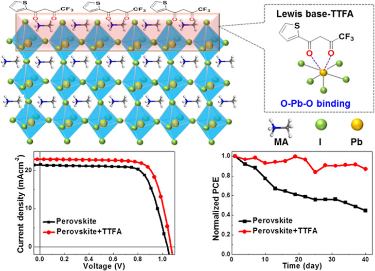
The chemical structures of the passivants PEAI, PI, BPY, DQCN, and TTFA are illustrated in Figure 1. PEAI26 and PI27 are used as reference due to their excellent passivation effect for high-efficiency PSCs. Different from common passivants having a single coordination site, BPY, DQCN, and TTFA have bi-coordination sites of “N/N”, “N/O”, and “O/O”, respectively, which are expected to coordinate with exposed “Pb” to form more stable coordination bonds; at the same time, the bulky aromatic groups are expected to enhance the hydrophobic property of the perovskite surface and thus prevent water intrusion.
To investigate the potential interactions between the passivants and perovskite, each passivant (1 mg/mL in isopropanol) was deposited on top of perovskite MAPbClxI3–x, and FTIR spectroscopy was performed to investigate change of the chemical bonds (Figures 2 and S1). Compared to “C=N” vibration at 1579 cm–1 in BPY, only a single vibration peak at a higher wavenumber of 1598 cm–1 appears in BPY-passivated pristine perovskite (PVK) (Figure 2a), which indicates that both “N” sites in BPY coordinate with exposed “Pb” in perovskite and form “N···Pb···N” coordination bonds. Compared to those of pure DQCN, the “C=O” and “C=N” vibrations for DQCN-passivated PVK show a slight shift from 1634 and 1578 to 1628 and 1584 cm–1, respectively (Figure 2b), which implies the formation of “C=O···Pb···N” coordination bonds. Compared to that of pure TTFA, the vibration of C=O linked to “CF3” or thiophene for TTFA-passivated PVK shows an obvious shift from 1663 or 1644 cm–1 to a lower wavenumber of 1638 or 1620 cm–1, respectively, indicating that both C=O bonds in TTFA formed “C=O···Pb···O=C” coordination bonds with “Pb” (Figure 2c).
Figure 2.

FTIR of PVK, passivants, and passivated perovskite. (a) PVK, BPY, and BPY-passivated PVK; (b) PVK, DQCN, and DQCN-passivated PVK; and (c) PVK, TTFA, and TTFA-passivated PVK.
3.2. Photophysical Property, Crystalline Structure, and Electric Property
To study the influence of passivation on perovskite, absorption spectroscopy, XRD, and UPS were conducted, and the results are shown in Figures 3, S2, and S3. The absorption and Tauc plots of MAPbClxI3–x films post-treatment with different passivants are presented in Figure 3a. The PVK shows an absorption edge at 776 nm, which slightly red-shifted to 779 nm after passivation with PEAI or TTFA and to 783 nm with BPY or DQCN. No visible change is observed for PI-passivated one, in accordance with the literature.27 The optical bandgap of perovskite is 1.617 eV which decreased to 1.605 eV after PEAI or TTFA passivation and to 1.603 eV after BPY or DQCN passivation. This phenomenon could be explained by the aromatic groups in PEAI, TTFA, BPY, or DQCN, which are richer in electrons than nonaromatic PI and thus increase the delocalization of perovskite hybrid orbits. The decrease in the bandgap indicates that there exists bonding interaction between the richer-electron passivant (BPY or DQCN) and perovskite. Figure 3b presents the XRD patterns of perovskite with and without passivation. All the films show similar and characteristic cubic perovskite diffraction peaks. The peaks of PVK appear at 14.11, 28.44, 31.89, and 40.68°, which can, respectively, be assigned to (110), (220), (310), and (330) diffractions34 and slightly shift to a lower angle of 14.07, 28.39, 31.83, and 40.61° after passivation by PEAI or PI and 14.08, 28.40, 31.85, and 40.63° after passivation by BPY, DQCN, or TTFA. No shift was observed for the sample treated with pure isopropanol (in Figure S2), which excludes the possible influence of the passivant deposition process on the property of perovskite. Therefore, from the shift of the diffraction peaks, it can be speculated that the passivant, especially a small-sized PEAI or PI molecule, can enter the interstitial lattice of perovskite and expand the cell unit.20,35 Furthermore, there is no obvious diffraction peak at 5.4°, indicating that 2D perovskite PEA2PbI4 did not form after passivation of PEAI, which is consistent with that reported in the literature.26 Also, 2D perovskite did not form after passivation of PI, as concluded by Jen et al.27 In addition, BPY, DQCN, and TTFA molecules do not contain an essential prerequisite aliphatic or aromatic alkylammonium spacer cation; therefore, 2D perovskite also cannot form after their passivation.36
Figure 3.

a) UV–vis absorption spectra of MAPbClxI3–x films with and without passivation. Inset: Tauc plots and the linear extrapolation of the bandgaps. (b) XRD patterns of MAPbClxI3–x films with and without passivation measured on NiOx/ITO/glass. The inset shows enlargement of the (110) peaks.
The highest occupied molecular orbital (HOMO) energy levels of perovskite films were derived from UPS (see Figure S3). The HOMO energy level of the PVK film is −5.50 eV and, respectively, descends to −5.63, −5.65, −5.62, −5.63, and −5.64 eV for the films passivated with PEAI, PI, BPY, DQCN, and TTFA. The lowest unoccupied molecular orbital (LUMO) energy levels of the PVK and that passivated with PEAI, PI, BPY, DQCN, and TTFA are −3.88, −4.02, −4.03, −4.02, −4.03, and −4.04 eV, respectively, which were calculated by subtracting the optical bandgaps from the HOMO levels. The energy diagram of the solar cell in Figure S4 shows that the LUMO energy level of passivated perovskite is much closer to 4.50 eV of C60, thus being beneficial for electron transfer from perovskite to the electron-transporting layer.
3.3. Surface Morphology
SEM and AFM were conducted to investigate the passivation influence on the morphology of perovskite films, and the results are shown in Figures 4 and S5. The PVK film is uniform and dense with clearly visible grain boundaries and a roughness (Ra) of 15.4 nm. After being passivated by PEAI, PI, BPY, DQCN, or TTFA, no significant change was observed in grain size and grain boundaries (Figure 4a) and surface roughness (Figure 4b), which indicates that the post-treatment passivation has little influence on the perovskite morphology.
Figure 4.

SEM (a) and AFM (b) images of the PVK film and films passivated by PEAI (PEAI + PVK), PI (PI + PVK), BPY (BPY + PVK), DQCN (DQCN + PVK), or TTFA (TTFA + PVK). The film roughness is shown as the inset in (b).
3.4. Photoluminescence
To further assess the passivation effect on the intrinsic properties of perovskite films, steady-state PL and TRPL spectra were recorded (see Figure 5). Compared to those of the pristine counterpart, all passivated perovskite films exhibit significantly enhanced PL intensity (Figure 5a), indicating that the non-radiative recombination of perovskite was inhibited, probably due to the passivation of the defects.37 The PL peak position of the PVK appears at 767 nm and, respectively, red-shifted to 771, 773, 772, and 771 nm after being passivated by PEAI, BPY, DQCN, and TTFA, which can be attributed to bandgap decrease after passivation (Figure 3a).26 No peak position change was observed for the PI-passivated film. The TRPL of the passivated perovskite films exhibits bi-exponential decays with a fast and a slow component, and the curves are all dominated by the slow decay process (Figure 5b). The fast decay is assigned to the nonradiative recombination process induced by the charge trapping, whereas the slow decay is related to the carrier recombination process.37,38 After being passivated by PEAI, PI, BPY, DQCN, or TTFA, the fast decay lifetime changed from 24.17 to 20.75, 30.64, 31.44, 26.89, or 33.01 ns, and the corresponding fraction significantly decreased from 35.93 to 7.07, 5.30, 9.62, 22.65, or 7.69%, respectively (Table S1); while the slow decay lifetime changed from 157.34 to 636.20, 464.83, 299.73, 212.14, or 576.22 ns, and the corresponding fraction greatly enhanced from 64.07 to 92.93, 94.70, 91.38, 77.35, or 92.31%, respectively (Table S1). The corresponding PL lifetime obtained from both sections of fast and slow decay significantly increased from 106.37 to 610.98, 441.73, 273.63, 168.80, or 534.25 ns, respectively (Figure 5b and Table S1). These results indicate that the passivated perovskite films have lower trap density and better electronic properties.38 The more efficient passivation effect of PEAI or PI than that of BPY or DQCN implies that there are more halide defects than Pb defects at the surface.25 The superior passivation effect of TTFA than that of PI, BPY, and DQCN can possibly be attributed to its relatively soft structure that benefits the coordination between “O” and “Pb” and a strong electron-drawing “–CF3” group that enables adjacent carbon as a Lewis acid and passivates halide defects.25 The PL results demonstrate that the passivation effect via the post-treatment strategy is greatly influenced by the type, the active sites, and/or the structure of the passivant.
Figure 5.

(a) PL spectra and (b) TRPL of the PVK film and perovskite films passivated by PEAI (PVK + PEAI), PI (PVK + PI), BPY (PVK + BPY), DQCN (PVK + DQCN), or TTFA (PVK + TTFA).
3.5. PSCs Using Organic Lewis Bases as Passivants
Using PEAI, PI, BPY, DQCN, or TTFA as the passivant, planar p–i–n PSCs with a structure of ITO/NiOx/MAPbClxI3–x/passivants/C60/BCP/Ag were fabricated. The current density–voltage (J–V) and EQE curves of the best performing devices using passivated and pristine perovskites are shown in Figures 6 and S6. The average device parameters with standard deviations are summarized in Table 1. The control device using PVK shows an efficiency of 15.75 with a JSC, VOC, and FF of 20.62 mA cm–2, 1.040 V, and 73.45%, respectively. When using PEAI-, PI-, or TTFA-passivated perovskite, the solar cell performance is significantly improved with a JSC, VOC, FF, and PCE of 22.52 mA cm–2, 1.090 V, 78.30, and 19.22% for PEAI, 21.76 mA cm–2, 1.097 V, 74.78, and 17.85% for PI, and 22.15 mA cm–2, 1.072 V, 75.29, and 17.88% for TTFA, respectively. For the BPY- or DQCN-passivated perovskites, the solar cell performance is slightly improved with a JSC, VOC, FF, and PCE of 20.94 mA cm–2, 1.054 V, 74.71, 16.49% for BPY and 21.42 mA cm–2, 1.052 V, 72.38, and 16.31% for DQCN, respectively. Compared to those of the reference passivants of PEAI and PI, BPY- and DQCN-based devices show inferior performance, while TTFA shows comparable performance. It can be explained that the neutral Lewis base molecules of BPY and DQCN can only passivate the undercoordinated “Pb”-induced defects, not the critical negative halide defects on the perovskite surface, thus leading to relatively more carrier recombination.27,39 However, TTFA possesses a more favorable structure feature for coordination with “Pb2+” and especially the Lewis acid characteristic generated by the strong electron-drawing “–CF3” group, which can passivate some halide defects via forming Lewis adducts.
Figure 6.

(a) J–V curves of the best performing MAPbClxI3–x solar cells with and without passivation treatment. (b) EQE spectra of the devices in (a). (c) Nyquist plots of the solar cells with MAPbClxI3–x passivated with PEAI, PI, BPY, DQCN, and TTFA measured at frequencies ranging from 2 × 10⁶ to 3 × 10⁻¹ Hz at 0.8 V bias voltages in dark in air. (d) Long-term stability of devices without encapsulation stored in a ∼12% humidity, low-oxygen level environment and tested in ∼50% humidity in air.
Table 1. Photovoltaic Parameters of PSCs Using Different Passivants.
| device (passivant) | VOC (V) | JSC (mA cm–2) | FF (%) | PCEmax (%) | Rs (Ω) | Rsh (kΩ) |
|---|---|---|---|---|---|---|
| control | 1.040 | 20.62 | 73.45 | 15.75 | 205.7 | 28.64 |
| PEAI | 1.090 | 22.52 | 78.30 | 19.22 | 129.9 | 99.76 |
| PI | 1.097 | 21.76 | 74.78 | 17.85 | 158.8 | 281.0 |
| BPY | 1.054 | 20.94 | 74.71 | 16.49 | 167.0 | 45.54 |
| DQCN | 1.052 | 21.42 | 72.38 | 16.31 | 177.4 | 70.14 |
| TTFA | 1.072 | 22.15 | 75.29 | 17.88 | 147.4 | 120.4 |
Devices using passivated MAPbClxI3–x show similar EQE curves in the wavelength range of 300–800 nm (Figure 6b). The JSC integrated from the EQE spectra is 19.63, 21.40, 20.76, 19.90, 20.35, and 21.05 mA cm–2 for the control, PEAI-, PI-, BPY-, DQCN-, and TTFA-based solar cells, respectively, in excellent agreement with the measured value from the J–V characterization in Figure 6a. Compared to the control device, PEAI-, PI-, and TTFA-based ones show higher EQE in the wavelength range of 300–800 nm (Figure 6b), probably attributed to the improvement of the charge transport and the reduction of non-radiative recombination. The series resistance (Rs) of PEAI-, PI-, and TTFA-based devices is smaller than that of the control ones (see Table 1). Compared to the control device, BPY-based ones exhibit slightly lower EQE between 460 and 570 nm but higher EQE between 650 and 800 nm; DQCN-based ones exhibit lower EQE between 350 and 430 nm but higher EQE between 650 and 800 nm. The higher EQE between 650 and 800 nm for BPY- and DQCN-based devices can be mainly attributed to the reduction of non-radiative recombination, while the lower EQE in the short-wave region cannot be explained. The significantly higher EQE and PCE for PEAI-, PI-, and TTFA-based devices both demonstrate that these passivants have effective passivation on the perovskite surface defects.
We further studied the electrochemical impedance spectra of the solar cells to explain the discrepancies in JSC, VOC, and FF as a function of the passivated perovskite (Figure 6c). Under an applied voltage of 0.8 V in the dark, the obviously visible arcs were recorded in the middle frequency, which are attributed to a recombination resistance, Rrec.37 The largest arcs for the PEAI-based device represent the highest internal Rrec and thus the lowest charge recombination than others, which corresponds to the highest VOC, JSC, and FF (Table 1).37,40 The similar arcs for TTFA- and PI-based devices can explain the little difference in VOC, JSC, and FF due to the similar charge recombination rate, which is roughly identical to that for BPY- and DQCN-based devices. Compared to those for TTFA- and PI-based devices, the much smaller arcs for the control, and BPY- or DQCN-based ones indicate a much higher charge combination rate, thus leading to much lower VOC, JSC, and FF.
To explore the effect of different passivants on the device stability, the PSCs without encapsulation were stored in a ∼12% humidity, low-oxygen level environment (O2 content of ∼150 ppm) and tested every 3 days in ∼50% humidity air. The samples were exposed to the ambient environment for ∼2 h each time during the test. As displayed in Figures 6d and S6, the control device exhibits a gradual increase in VOC and a continuous fast decrease in JSC with fluctuant FF around 70%, leading to a fast drop in PCE. Compared to that of the control device, the VOC for PI-, BPY-, DQCN-, and TTFA-based devices exhibits a similar increasing trend while that for the PEAI-based device shows a slight decrease during the first 4 weeks before evening out (Figure S7a). The JSC for devices with passivation shows a slower and fluctuant decrease during the storage while a relatively fast decrease for the PI-based device (Figure S7b). The FF for the PEAI-, BPY-, DQCN-, or TTFA-based device exhibits no obvious change with only small fluctuation during the storage but a significant decrease for the PI-based device (Figure S7c). After being stored for 40 days with a total test for 14 times, the efficiencies of the devices show a 45.4, 38.8, 44.4, 13.2, 16.7, and 12.9% drop for the control, PEAI-, PI-, BPY-, DQCN-, and TTFA-based devices, respectively (Figure 6d).
In order to understand the origin of stability difference of the passivated perovskite, the surface properties of the perovskite films were investigated, such as hydrophobicity and the stability of molecular bonding between “Pb” and passivants. As shown in Figure 7a, the water contact angle of the PVK surface is 33.8°, which is increased to 51.2, 48.7, 69.3, 62.8, and 66.3° for PEAI-, PI-, BPY-, DQCN-, and TTFA-passivated perovskite surfaces, respectively, indicating the improved hydrophobicity induced by the hydrophobic organic passivant molecules adhering to the perovskite surface. Compared to those of the zwitterion passivants of PEAI and PI, the bulky aromatic moieties in organic BPY, DQCN, and TTFA make the perovskite surface much more hydrophobic, which is probably the primary reason for BPY-, DQCN-, and TTFA-based devices exhibiting obviously higher stability than PEAI- and PI-based devices. Furthermore, compared to BPY bearing a highly hydrophobic “pyridine” group and TTFA bearing extremely hydrophobic “thiophene” and “–CF3” groups, DQCN contains “N–H” and “–CN” polar groups, which are prone to form hydrogen bonds with H2O, thus leading to a slightly lower hydrophobic perovskite surface, accounting for relatively slightly inferior device stability. As shown in Figure 7b, a layer of MAPbI3 crystal configuration31 was selected as the calculation model for passivant molecular adsorption energies. PEAI offers “I” ions to coordinate with exposed “Pb”, and PEA+ (2-phenylethan-1-aminium) is the counter ion adhering to the perovskite surface. PI can offer “I” ions or “N” to coordinate with exposed “Pb”, forming two conformations on the perovskite surface. The passivants BPY, DQCN, and TTFA form the “N–Pb” or “O–Pb” coordination bonds on the perovskite surface, which has been confirmed by FTIR characterization. According to the cases of coordination, interacting conformations between the passivant molecules and perovskite surface and the bond distance were optimized through DFT calculations.31,32 The results demonstrate that the absorption energies of the passivant molecules on the perovskite surface are −0.5759 eV for PEAI, −0.6477 eV (formation of the “I–Pb” coordination bond) or −0.7681 eV (formation of the “N–Pb” coordination bond) for PI, −0.7472 eV for BPY, −6.1894 eV for DQCN, and −5.9192 eV for TTFA (see Table S2). For PEAI or PI, this absorption energy is mainly contributed from “I–Pb” coordination interaction and electrostatic attraction between positive and negative ions, while for BPY, DQCN, or TTFA, it originates from the contribution of “N–Pb–N”, “N–Pb–O”, or “O–Pb–O” coordination interaction, respectively. The higher the adsorption energy, the stronger the interaction between the passivant molecule and perovskite; therefore, DQCN and TTFA molecules have much stronger interaction with perovskite; thus, they are less likely to be lost or be replaced by other foreign molecules, which is probably another factor for the better stability of their devices. In addition, the coordination bond lengths for BPY, DQCN, or TTFA are far smaller than the diameter of H2O (4.0 Å) or O2 (3.5 Å), which can form a larger steric hindrance against the invasion of H2O or O2 molecules of perovskite surface defects. This can explain why BPY-based devices can exhibit good stability despite the small adsorption energy of BPY molecules on the perovskite surface. These characterization results demonstrate that the variation of perovskite surface hydrophobicity after passivation is the primary influencing factor for the discrepancy of device stability. In the case of similar perovskite surface hydrophobicity, the high adsorption energy and short bonding length between passivant molecules and perovskite are favorable to device stability.
Figure 7.

(a) Contact angle of water droplets on the perovskite films passivated by PEAI (PVK + PEAI), PI (PVK + PI), BPY (PVK + BPY), DQCN (PVK + DQCN), or TTFA (PVK + TTFA), with the PVK film as reference. (b) Theoretical simulation of the perovskite/passivant interfaces and theoretical calculation for the energy of the coordination bonds formed between the undercoordinated “Pb” atom and “N” or “O” atom. The enlarged area below describes the coordination bonds and their optimized lengths.
4. Conclusions
In summary, three organic Lewis bases (BPY, DQCN, and TTFA) with bi-coordination sites of N or O were first employed as passivants for perovskite surface defects via a post-treatment approach. The typical zwitterion PEAI and PI passivants were used as reference. FTIR, UV–vis, and UPS characterizations reveal that BPY, DQCN, or TTFA has formed the coordination bonds between their active sites and exposed “Pb” and was probably involved in the orbital hybridization of perovskite, leading to the slight decrease in HOMO or LUMO energy levels and bandgaps. XRD, SEM, and AFM characterizations demonstrate that only minimal passivants especially small-size PEAI or PI entered the interstitial lattice site of perovskite, leading to a slightly expanded unit cell, while most passivants were anchored to the perovskite surface, having almost no influence on the perovskite grains and surface morphology. PL and TRPL characterizations indicate that all these passivants can passivate the perovskite surface defects to inhibit non-radiative recombination. The passivation effect via this post-treatment strategy is primarily impacted by the defect type of the perovskite surface and the type and structure of passivants. Utilizing the passivated perovskite as the light absorption layer, the solar cells with an inverted configuration of ITO/NiOx/MAPbClxI3–x/passivants/C60/BCP/Ag have been successfully fabricated, and efficiencies of 19.22, 17.85, 16.49, 16.31, and 17.88% have been achieved from PEAI-, PI-, BPY-, DQCN-, and TTFA-passivated perovskite, respectively. All the device performance based on the passivated perovskite is superior to that of the control ones (15.75%) owing to the fact that the interior carrier recombination of the devices was effectively inhibited via passivating the defects of the perovskite surface. Especially, the devices from the TTFA-passivated perovskite exhibit almost comparable efficiencies to those based on the typical PEAI and PI passivants, indicating that TTFA has an equal excellent passivation effect to PEAI and PI. Furthermore, the devices based on BPY-, DQCN-, or TTFA-passivated perovskites show superior long-term stability with an efficiency loss of only 13.2, 16.7, or 12.9%, respectively, but 45.4, 38.8, and 44.4% for the control, PEAI-, or PI-based ones, respectively, after being stored for 40 days in a ∼12% humidity, low-oxygen level environment. The contact angle test and interaction simulation calculation between the passivant and perovskite surface reveal that BPY, DQCN, or TTFA passivation can significantly improve the surface hydrophobicity of perovskite, and also, DQCN or TTFA can form much stronger interactions at slightly shorter distance with perovskite. These results indicate that the variation of perovskite surface hydrophobicity after passivation is the primary influencing factor for the discrepancy of device stability. In the case of similar perovskite surface hydrophobicity, the high adsorption energy and short bonding length between passivant molecules and perovskite are favorable to device stability, which can explain why TTFA-based devices show better stability than BPY-based ones. Our results demonstrate that it is feasible to achieve high-efficiency and long-term-stable PSCs via selecting the appropriate molecules to passivate the dominant defects of the perovskite surface.
Acknowledgments
This work was supported by the National Natural Science Foundation of China (NSFC, grant no. 22075150) and the National Key Research and Development Program of China (grant no. 2019YFE0118100).
Supporting Information Available
The Supporting Information is available free of charge at https://pubs.acs.org/doi/10.1021/acsomega.2c03802.
FTIR, UPS, TRPL, SEM, and AFM characterization results, energy level configuration of the devices, and DFT calculation results (PDF)
The authors declare no competing financial interest.
Supplementary Material
References
- Kojima A.; Teshima K.; Shirai Y.; Miyasaka T. Organometal halide perovskites as visible-light sensitizers for photovoltaic cells. J. Am. Chem. Soc. 2009, 131, 6050–6051. 10.1021/ja809598r. [DOI] [PubMed] [Google Scholar]
- Min H.; Lee D. Y.; Kim J.; Kim G.; Lee K. S.; Kim J.; Paik M. J.; Kim Y. K.; Kim K. S.; Kim M. G.; Shin T. J.; Il Seok S. I. Perovskite solar cells with atomically coherent interlayers on SnO2 electrodes. Nature 2021, 598, 444–450. 10.1038/s41586-021-03964-8. [DOI] [PubMed] [Google Scholar]
- Zhang S.; Liu Z.; Zhang W.; Jiang Z.; Chen W.; Chen R.; Huang Y.; Yang Z.; Zhang Y.; Han L.; Chen W. Barrier designs in perovskite solar cells for long-term stability. Adv. Energy Mater. 2020, 10, 2001610. 10.1002/aenm.202001610. [DOI] [Google Scholar]
- Duan L.; Chen Y.; Yuan J.; Zong X.; Sun Z.; Wu Q.; Xue S. Dopant-free X-shaped D-A type hole-transporting materials for p-i-n perovskite solar cells. Dyes Pigm. 2020, 178, 108334. 10.1016/j.dyepig.2020.108334. [DOI] [Google Scholar]
- Zhang H.; Lv Y.; Wang J.; Ma H.; Sun Z.; Huang W. Influence of Cl incorporation in perovskite precursor on the crystal growth and storage stability of perovskite solar cells. ACS Appl. Mater. Interfaces 2019, 11, 6022–6030. 10.1021/acsami.8b19390. [DOI] [PubMed] [Google Scholar]
- Yang G.; Ren Z.; Liu K.; Qin M.; Deng W.; Zhang H.; Wang H.; Liang J.; Ye F.; Liang Q.; Yin H.; Chen Y.; Zhuang Y.; Li S.; Gao B.; Wang J.; Shi T.; Wang X.; Lu X.; Wu H.; Hou J.; Lei D.; So S. K.; Yang Y.; Fang G.; Li G. Stable and low-photovoltage-loss perovskite solar cells by multifunctional passivation. Nat. Photonics 2021, 15, 681–689. 10.1038/s41566-021-00829-4. [DOI] [Google Scholar]
- Xu B.; Zhu Z.; Zhang J.; Liu H.; Chueh C.-C.; Li X.; Jen A. K.-Y. 4-Tert-butylpyridine free organic hole transporting materials for stable and efficient planar perovskite solar cells. Adv. Energy Mater. 2017, 7, 1700683. 10.1002/aenm.201700683. [DOI] [Google Scholar]
- Li F.; Shen Z.; Weng Y.; Lou Q.; Chen C.; Shen L.; Guo W.; Li G. Novel electron transport layer material for perovskite solar cells with over 22% efficiency and long-term stability. Adv. Funct. Mater. 2020, 30, 2004933. 10.1002/adfm.202004933. [DOI] [Google Scholar]
- He J.; Su J.; Lin Z.; Ma J.; Zhou L.; Zhang S.; Liu S.; Chang J.; Hao Y. Enhanced efficiency and stability of all-inorganic CsPbI2Br perovskite solar cells by organic and ionic mixed passivation. Adv. Sci. 2021, 8, 2101367. 10.1002/advs.202101367. [DOI] [PMC free article] [PubMed] [Google Scholar]
- Shen W.; Dong Y.; Huang F.; Cheng Y.; Zhong J. Interface passivation engineering for hybrid perovskite solar cells. Mater. Rep. Energy 2021, 1, 100060. 10.1016/j.matre.2021.100060. [DOI] [Google Scholar]
- Guo X.; Su J.; Lin Z.; Wang X.; Wang Q.; Zeng Z.; Chang J.; Hao Y. Synergetic surface charge transfer doping and passivation toward high efficient and stable perovskite solar cells. iScience 2021, 24, 102276. 10.1016/j.isci.2021.102276. [DOI] [PMC free article] [PubMed] [Google Scholar]
- Zhou L.; Su J.; Lin Z.; Guo X.; Ma J.; Li T.; Zhang J.; Chang J.; Hao Y. Synergistic interface layer optimization and surface passivation with fluorocarbon molecules toward efficient and stable inverted planar perovskite solar cells. Research 2021, 2021, 9836752. 10.34133/2021/9836752. [DOI] [PMC free article] [PubMed] [Google Scholar]
- Zhang L.; Zhou X.; Zhong X.; Cheng C.; Tian Y.; Xu B. Hole-transporting layer based on a conjugated polyelectrolyte with organic cations enables efficient inverted perovskite solar cells. Nano Energy 2019, 57, 248–255. 10.1016/j.nanoen.2018.12.033. [DOI] [Google Scholar]
- Heo J. H.; Park S.; Im S. H.; Son H. J. Development of dopant-free donor–acceptor-type hole transporting material for highly efficient and stable perovskite solar cells. ACS Appl. Mater. Interfaces 2017, 9, 39511–39518. 10.1021/acsami.7b11938. [DOI] [PubMed] [Google Scholar]
- Liu Y.; Page Z. A.; Zhou D.; Duzhko V. V.; Kittilstved K. R.; Emrick T.; Russell T. P. Chemical stabilization of perovskite solar cells with functional fulleropyrrolidines. ACS Cent. Sci. 2018, 4, 216–222. 10.1021/acscentsci.7b00454. [DOI] [PMC free article] [PubMed] [Google Scholar]
- Li J.; Xia R.; Qi W.; Zhou X.; Cheng J.; Chen Y.; Hou G.; Ding Y.; Li Y.; Zhao Y.; Zhang X. Encapsulation of perovskite solar cells for enhanced stability: Structures, materials and characterization. J. Power Sources 2021, 485, 229313. 10.1016/j.jpowsour.2020.229313. [DOI] [Google Scholar]
- Gao F.; Zhao Y.; Zhang X.; You J. Recent progresses on defect passivation toward efficient perovskite solar cells. Adv. Energy Mater. 2020, 10, 1902650. 10.1002/aenm.201902650. [DOI] [Google Scholar]
- Zhao W.; Xu J.; He K.; Cai Y.; Han Y.; Yang S.; Zhan S.; Wang D.; Liu Z.; Liu S. A special additive enables all cations and anions passivation for stable perovskite solar cells with efficiency over 23%. Nano-Micro Lett. 2021, 13, 169. 10.1007/s40820-021-00688-2. [DOI] [PMC free article] [PubMed] [Google Scholar]
- Byranvand M. M.; Saliba M. Defect passivation of perovskite films for highly efficient and stable solar cells. Sol. RRL 2021, 5, 2100295. 10.1002/solr.202100295. [DOI] [Google Scholar]
- Zhang Y.; Wang Y.; Zhao L.; Yang X.; Hou C.-H.; Wu J.; Su R.; Jia S.; Shyue J.-J.; Luo D.; Chen P.; Yu M.; Li Q.; Li L.; Gong Q.; Zhu R. Depth-dependent defect manipulation in perovskites for high-performance solar cells. Energy Environ. Sci. 2021, 14, 6526–6535. 10.1039/d1ee02287c. [DOI] [Google Scholar]
- Yin Y.; Guo Z.; Chen G.; Zhang H.; Yin W.-J. Recent progress in defect tolerance and defect passivation in halide perovskite solar cells. Acta Phys.-Chim. Sin. 2021, 37, 2008048. 10.3866/PKU.WHXB202008048. [DOI] [Google Scholar]
- Lin Y.; Shen L.; Dai J.; Deng Y.; Wu Y.; Bai Y.; Zheng X.; Wang J.; Fang Y.; Wei H.; Ma W.; Zeng X. C.; Zhan X.; Huang J. π-Conjugated Lewis base: efficient trap-passivation and charge-extraction for hybrid perovskite solar cells. Adv. Mater. 2017, 29, 1604545. 10.1002/adma.201604545. [DOI] [PubMed] [Google Scholar]
- Sutanto A. A.; Igci C.; Kim H.; Kanda H.; Shibayama N.; Mensi M.; Queloz V. I. E.; Momblona C.; Yun H. J.; Bolink H. J.; Huckaba A. J.; Nazeeruddin M. K. Phosphine oxide derivative as a passivating agent to enhance the performance of perovskite solar cells. ACS Appl. Energy Mater. 2021, 4, 1259–1268. 10.1021/acsaem.0c02472. [DOI] [Google Scholar]
- Liu B.; Bi H.; He D.; Bai L.; Wang W.; Yuan H.; Song Q.; Su P.; Zang Z.; Zhou T.; Chen J. Interfacial defect passivation and stress release via multi-active-site ligand anchoring enables efficient and stable methylammonium-free perovskite solar cells. ACS Energy Lett. 2021, 6, 2526–2538. 10.1021/acsenergylett.1c00794. [DOI] [Google Scholar]
- Yang Z.; Dou J.; Kou S.; Dang J.; Ji Y.; Yang G.; Wu W.; Kuang D.; Wang M. Multifunctional phosphorus-containing Lewis acid and base passivation enabling efficient and moisture-stable perovskite solar cells. Adv. Funct. Mater. 2020, 30, 1910710. 10.1002/adfm.201910710. [DOI] [Google Scholar]
- Jiang Q.; Zhao Y.; Zhang X.; Yang X.; Chen Y.; Chu Z.; Ye Q.; Li X.; Yin Z.; You J. Surface passivation of perovskite film for efficient solar cells. Nat. Photonics 2019, 13, 460–466. 10.1038/s41566-019-0398-2. [DOI] [Google Scholar]
- Li F.; Deng X.; Qi F.; Li Z.; Liu D.; Shen D.; Qin M.; Wu S.; Lin F.; Jang S.-H.; Zhang J.; Lu X.; Lei D.; Lee C.-S.; Zhu Z.; Jen A. K.-Y. Regulating surface termination for efficient inverted perovskite solar cells with greater than 23% efficiency. J. Am. Chem. Soc. 2020, 142, 20134–20142. 10.1021/jacs.0c09845. [DOI] [PubMed] [Google Scholar]
- Wang S.; Wang A.; Deng X.; Xie L.; Xiao A.; Li C.; Xiang Y.; Li T.; Ding L.; Hao F. Lewis acid/base approach for efficacious defect passivation in perovskite solar cells. J. Mater. Chem. A 2020, 8, 12201–12225. 10.1039/d0ta03957h. [DOI] [Google Scholar]
- He J.; Fang W.; Long R.; Prezhdo O. V. Bidentate Lewis bases are preferred for passivation of MAPbI3 surfaces: A time-domain ab initio analysis. Nano Energy 2021, 79, 105491. 10.1016/j.nanoen.2020.105491. [DOI] [Google Scholar]
- Yan W.; He Z.; Jiang J.; Lu D.; Gong Y.; Yang W.; Xia R.; Huang W.; Xin H. Highly thermal-stable perylene-bisimide small molecules as efficient electron-transport materials for perovskite solar cells. J. Mater. Chem. C 2020, 8, 14773–14781. 10.1039/d0tc04241b. [DOI] [Google Scholar]
- Qin H.; Xu L.; Zhong D. First-principles study of zinc phthalocyanine molecules adsorbed on methylammonium lead iodide surfaces. J. Phys. Chem. C 2020, 124, 5167–5173. 10.1021/acs.jpcc.9b10664. [DOI] [Google Scholar]
- Huang L.; Dong H.; Huo N.; Zheng Z.; Deng H.; Zhang G.; Cheng Y.; Li J. Deep insights into interface engineering by buffer layer for efficient perovskite solar cells: a first principles study. Sci. China Mater. 2020, 63, 1588–1596. 10.1007/s40843-020-1322-2. [DOI] [Google Scholar]
- Dang Y.; Liu Y.; Sun Y.; Yuan D.; Liu X.; Lu W.; Liu G.; Xia H.; Tao X. Bulk crystal growth of hybrid perovskite material CH3NH3PbI3. CrystEngComm 2015, 17, 665–670. 10.1039/c4ce02106a. [DOI] [Google Scholar]
- Rao H.; Ye S.; Sun W.; Yan W.; Li Y.; Peng H.; Liu Z.; Bian Z.; Li Y.; Huang C. A 19.0% efficiency achieved in CuOx-based inverted CH3NH3PbI3-xClx solar cells by an effective Cl doping method. Nano Energy 2016, 27, 51–57. 10.1016/j.nanoen.2016.06.044. [DOI] [Google Scholar]
- Min H.; Kim M.; Lee S.-U.; Kim H.; Kim G.; Choi K.; Lee J. H.; Seok S. I. Efficient, stable solar cells by using inherent bandgap of α-phase formamidinium lead iodide. Science 2019, 366, 749–753. 10.1126/science.aay7044. [DOI] [PubMed] [Google Scholar]
- Chen Y.; Sun Y.; Peng J.; Tang J.; Zheng K.; Liang Z. 2D Ruddlesden–Popper perovskites for optoelectronics. Adv. Mater. 2017, 30, 1703487. 10.1002/adma.201703487. [DOI] [PubMed] [Google Scholar]
- Li M.; Yu L.; Zhang Y.; Gao H.; Li P.; Chen R.; Huang W. Multiple passivation of electronic defects for efficient and stable perovskite solar cells. Sol. RRL 2020, 4, 2000481. 10.1002/solr.202000481. [DOI] [Google Scholar]
- Wang R.; Xue J.; Meng L.; Lee J.-W.; Zhao Z.; Sun P.; Cai L.; Huang T.; Wang Z.; Wang Z.-K.; Duan Y.; Yang J. L.; Tan S.; Yuan Y.; Huang Y.; Yang Y. Caffeine improves the performance and thermal stability of perovskite solar cells. Joule 2019, 3, 1464–1477. 10.1016/j.joule.2019.04.005. [DOI] [Google Scholar]
- Chen B.; Rudd P. N.; Yang S.; Yuan Y.; Huang J. Imperfections and their passivation in halide perovskite solar cells. Chem. Soc. Rev. 2019, 48, 3842–3867. 10.1039/c8cs00853a. [DOI] [PubMed] [Google Scholar]
- Yan W.; Li Y.; Ye S.; Li Y.; Rao H.; Liu Z.; Wang S.; Bian Z.; Huang C. Increasing open circuit voltage by adjusting work function of hole-transporting materials in perovskite solar cells. Nano Res. 2016, 9, 1600–1608. 10.1007/s12274-016-1054-5. [DOI] [Google Scholar]
Associated Data
This section collects any data citations, data availability statements, or supplementary materials included in this article.