Abstract
Objective
To compare the biomechanical properties of proximal femur bionic nail (PFBN), proximal femoral nail antirotation (PFNA) and InterTan in the treatment of elderly intertrochanteric fractures AO/OTA 31‐A1.3 by finite element analysis.
Methods
We used Mimics, Unigraphics and other software to establish normal femur and AO/OTA 31‐A1.3 fracture models, and reconstructed PFBN, PFNA and InterTan intramedullary nail models, and assembled them on the fracture model. The ANSYS software was used to compare the femoral von Mises stress distribution, deformation distribution, and internal fixation stress distribution of each group under a load of 2100 N.
Results
It could be seen that the femoral maximum stress, femoral maximum displacement, and maximum stress of internal fixation of the PFBN group were lower than those in the PFNA group and the InterTan group. The maximum femoral stress of the PFBN was 190.25 MPa, while the maximum stress of the femur of the PFNA and InterTan groups were 238.41 Mpa and 226.97 Mpa. The maximum femoral displacement of each group were located at the top of the femoral head, and the maximum displacement of the PFBN group was 14.373 mm, and the maximum displacement values of the PFNA and InterTan groups were 19.49 and 15.225 mm. For the stress distribution of intramedullary nail, the maximum stress of the three kinds of internal fixation was located on the main nail. The maximum stress of PFBN was 1191.8 MPa, compared with 2142.8 MPa for PFNA and 1702.3 MPa for InterTan. And the maximum stress on the PFBN pressure nail was 345.35 MPa, compared with 868.6 MPa for the PFNA spiral blade and 545.5 MPa for InterTan interlocking twin nails.
Conclusion
Compared with PFNA and InterTan, PFBN has better mechanical properties. The biomechanical characteristics of PFBN are more advantageous than PFNA and InterTan internal fixation system in the treatment of femoral intertrochanteric fractures.
Keywords: Finite element analysis, InterTan, Intertrochanteric fracture, PFNA, Proximal femur bionic nail
We developed a new type of intramedullary fixation named Proximal Femur Bionic Nail (PFBN) and compared its biomechanical properties with Proximal Femur Bionic Nail(PFNA) and InterTAN by finite element analysis. The results showed that the femoral stress, femoral displacement and intramedullary nail stress in PFBN group were lower than those in PFNA group and InterTan group, and suggested PFBN is a promising new intramedullary nail.
Introduction
Incidence of hip fractures is getting higher with the aging of population, which are approximately 1.6 million worldwide each year and will reach 4.5 to 6.3 million by 2050, and hip fracture has become the most harmful fracture to the elderly due to its high motality 1 , 2 , 3 , 4 . Among hip fractures, intertrochanteric fractures account for about 41%‐50% 5 . For the treatment of intertrochanteric fractures, early firm internal fixation of the fracture is recommended and it helps patients get early rehabilitation and avoid complications such as pneumonia and venous thrombus embolism, and current research suggests intramedullary fixation for most situations of intertrochanteric fracture 6 , 7 . However there is still a 6%‐21% probability of internal fixation related complications such as coxa vara deformity, screw cutout, nail removal, fracture of internal fixation and femoral neck shortening. Especially in elderly patients, the failure rate of internal fixation can be as high as 30% 8 , 9 , 10 , 11 .
In response to internal fixation related complications, Zhang Y et al. proposed that triangular stabilization structure can reduce the risk of failure of internal fixation of intertrochanteric fractures, and declared a national invention patent 12 . And Zhang D et al. combined the morphological, anatomical and biomechanical characteristics of the proximal femur, and proposed the lever‐balance‐reconstruction theory of internal fixation in treating intertrochanteric fractures 13 , 14 . The theory holds that the normal structure of the proximal femur is similar to a lever, and its fulcrum is located near the center of the femoral head. The medial pressure arm of the femur is short, and the lateral tension arm is long, so it can bear greater compressive stress. After the fracture, the original lever system is destroyed. The purpose of internal fixation is to establish a new lever system to replace the original lever system and bring the new fulcrum closer to the original anatomical fulcrum. Based on the original patent of the triangular stabilization structure of Zhang Y and the lever balance reconstruction theory proposed by Zhang D, a new type of proximal femoral bionic internal fixation intramedullary nail (PFBN) was designed 12 , 13 , 14 , 15 . The system includes a main nail, a pressure nail, and a tension nail, which are combined with each other to form a stable structure. Through the combination of the pressure nail and the tension nail, the bionic reconstruction of the pressure trabecular and the tension trabecular of the proximal femur is realized. It can resist the compressive stress and tensile stress generated by weight‐bearing after the fracture operation, so that the fulcrum of fracture reconstruction is close to the anatomical fulcrum. This kind of bionic design internal fixation has better stability theoretically, and the purpose of this study is to: (i) access the biomechanical properties of PFBN compared with traditional intramedullary nails including proximal femoral nails antirotation (PFNA) and InterTan by using finite element analysis; and (ii) provide new ideas for the treatment and research of elderly femoral intertrochanteric fractures (Figures 1, 2, 3, 4, 5).
FIGURE 1.
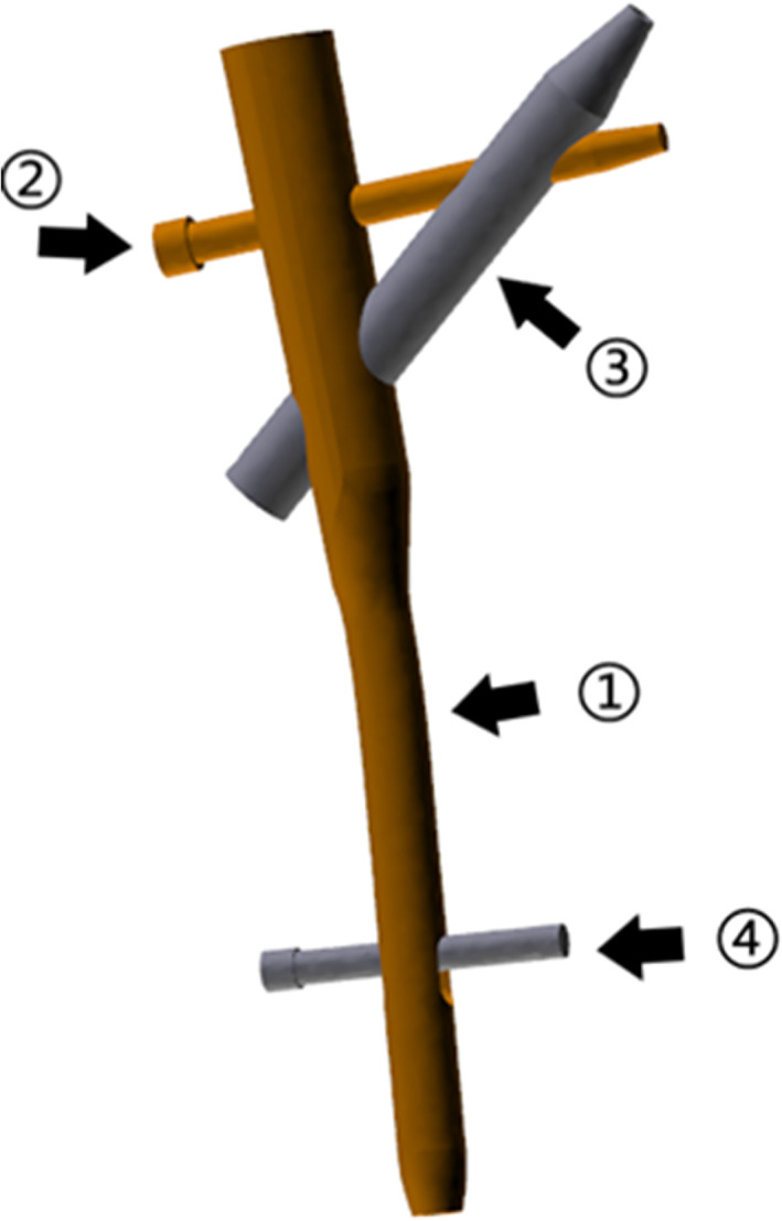
The three‐dimensional model of the new type of proximal femur bionic internal fixation intramedullary nail (proximal femur bionic nail, PFBN), consists of ① Main nail; ② Tension nail; ③ Pressure nail; ④ Lock nail
FIGURE 2.
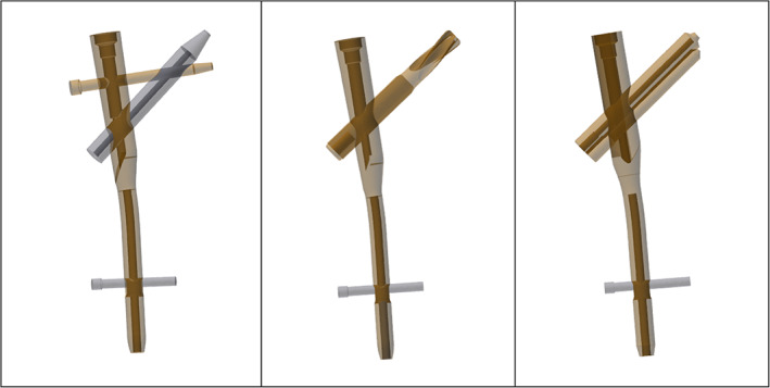
The three‐dimensional geometric model of proximal femur bionic nail (PFBN), proximal femoral nail antirotation (PFNA) and InterTan
FIGURE 3.
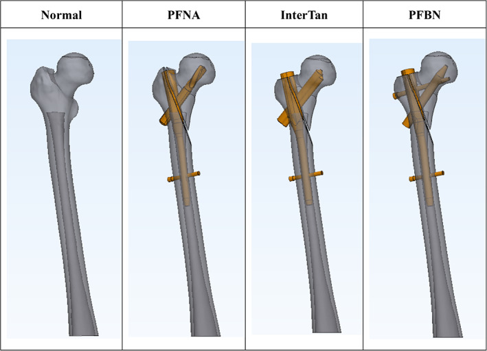
Normal femur and assembly diagram of fracture model with different intramedullary nails of proximal femur bionic nail (PFBN), PFNA and InterTan
FIGURE 4.
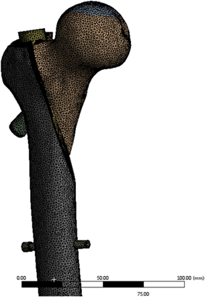
The meshed model of proximal femur with intramedullary nail in the 3‐matic
FIGURE 5.

Set the 30 mm diameter range above the femoral head as the loading surface, and set the femoral condyle as the restraining surface
Methods
Establish the Fracture Model and Intramedullary Nail Model
Femoral CT images of an elderly woman (65 years old, height 168 cm, weight 70 kg, no previous femoral disease) were selected, and the CT dicom files were imported into Mimics 21.0 (Materialise, Leuven, Belgium) software to establish a three‐dimensional femoral model, and the model was segmented according to the characteristics of AO/OTA 31‐A3.1 fractures to establish a fracture model 16 . The three‐dimensional geometric model of the intramedullary nail was established in Unigraphics NX 12.0 (Siemens PLM Software, Munich, Germany) according to the size of the intramedullary nail provided by the manufacturer, complete the assembly of the intramedullary nail model, and export the geometric model file.
Model Assembly
The model of the femur and the intramedullary nail were imported into the 3‐matic 13.0 (Materialise, Leuven, Belgium), and we used the rotation and translation function to adjust the position of the intramedullary nail. According to the manufacturer's instructions, make it consistent with the fixed position of the operation. Then we set the area with a diameter of 30 mm on femoral head as the loading surface and set the area with a height of 40 mm at the bottom of the femoral condyle as the fixed surface.
Meshing
In the 3‐matic software, the model mesh size is 1.5 mm, and the mesh quality is checked and optimized, and the second‐order 10‐node tetrahedral mesh (solid187) is generated according to the surface mesh (Figure 4).
Material Properties
With reference to the method recommended in the previous literature, the Young's modulus of cortical bone and cancellous bone was set to 17,000 and 445 MPa, and the Poisson's ratio was set to 0.3 and 0.2, and the Young's modulus of the Internal fixation was set to 113,800 MPa, and the Poisson's ratio was 0.342 17 .
Boundary and Loading Conditions
The contact conditions were set as friction contact, the friction coefficient between bone and bone was 0.46, the friction coefficient between bone and nail was 0.42, and the friction coefficient between nail and nail was 0.2 18 . The load condition is set to 2100 N, and the direction is normal standing angle vertical down. Set the 30 mm diameter range above the femoral head as the loading surface, and set the restraint surface at the femoral condyle to be fully fixed (Figure 5) 19 .
Observation Index
The von Mises stress distribution and the model displacements of the whole femur and the stress distribution of femoral head is output respectively using ANSYS Workbench 2020R2 (ANSYS Canonsburg, PA, USA). The stress distribution of the intramedullary nail system under seven equidistant load conditions under 300 to 2100 N is also extracted, referring to previous similar studies 17 , 20 , 21 , 22 , 23 .
Results
The Results of von Mises Stress Distribution of the Femur
The results (Figure 6) showed that three models of intramedullary nail fixation have uneven stress distribution and stress concentration. The maximum stress distribution of the three groups was all located in the lateral cortex. The maximum stress in the PFNA group was 238.41 MPa at the intersection of the distal locking nail and the lateral cortex. The stress in the InterTan group was 226.97 MPa. The maximum stress in the PFBN group was concentrated under the greater trochanter of the lateral cortex. The maximum stress was 190.25 MPa, which was smaller than the PFNA group and the InterTan group.
FIGURE 6.
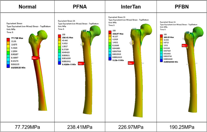
The von Mises stress distribution of normal femur and fractured femur fixed with three kinds of intramedullary nails under a load of 2100 N. The maximum stress of proximal femur bionic nail (PFBN) group is the smallest among the three groups
Model Displacement of the Femur
The deformation of the three groups of femoral models (Figure 7) is concentrated on the position of the femoral head subjected to compressive stress. Among them, the normal femoral displacement value was 10.127 mm, while the maximum displacement value of InterTan group was 15.225 mm, and that of the PFNA group was 19.49 mm, while the PFBN group had the minimum displacement of 14.373 mm in the internal fixation group.
FIGURE 7.
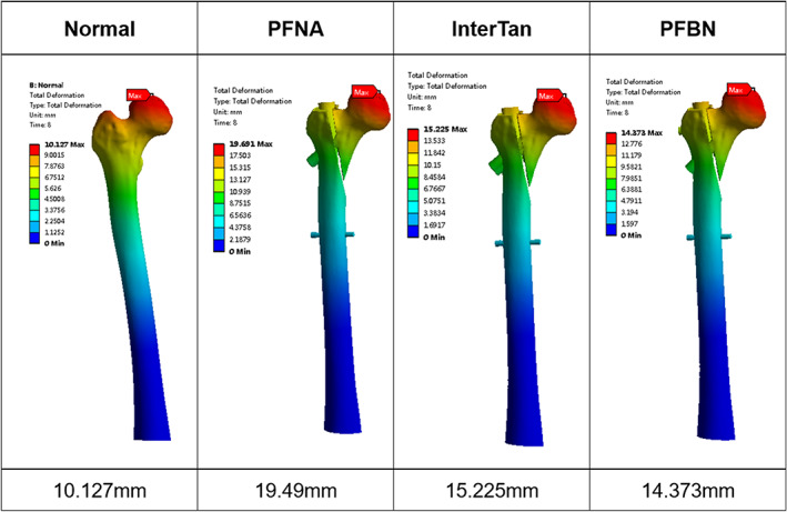
Displacement of the proximal femur of normal femur and fractured femur fixed with three kinds of intramedullary nails under a load of 2100 N. The deformation of the three groups of models is concentrated on the position of the femoral head, and the deformation value of the proximal femur bionic nail (PFBN) group is smaller than other two groups
Stress Distribution of Femoral Head and Proximal Fracture Fragment
In order to show the bone stress at the tip of each internal fixation screw, we extract the stress distribution of the femoral head and proximal fracture fragment of the femur (Figures 8 and 9). The maximum stress in the PFNA group was at the tip of the spiral blade, which was 25.375 MPa. The maximum stress of the InterTan group was 34.218 MPa at the tip of the integrated twin nails. The maximum stress of the PFBN group was at the upper edge of the pressure nail, which was 13.856 MPa and smaller than that of the PFNA group and InterTan group. As the PFBN group shown in the displacement figure presented the smallest displacement of the femoral head, and the risk of screw cutout of the femoral head is lower.
FIGURE 8.
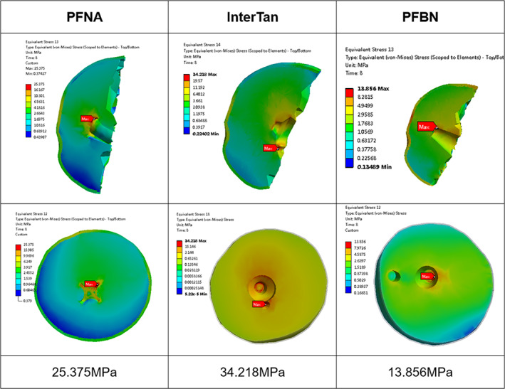
Stress distribution of the femoral screw in the femoral head of the three internal fixations under a load of 2100 N showed in coronal and axis section. The stress of each group is concentrated at the tip of the nail
FIGURE 9.
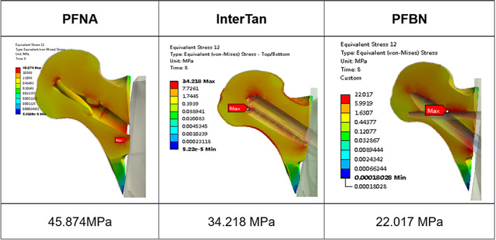
The stress distribution in the proximal fracture fragment of the femur under three internal fixations. The maximum stress in the proximal femur bionic nail (PFBN) group was at the intersection of tension nail and pressure nail different from proximal femoral nail antirotation (PFNA) and InterTan group
From the result of the maximum stress distribution in the proximal femoral fracture fragments, we could see that maximum stress in the PFNA group was distributed at the intersection of the screw and the fracture surface. The maximum stress in the InterTan group was still at the tip of the twin nails, while the maximum stress in the PFBN group was at the intersection of tension nail and pressure nail, and the value was 22.017 MPa.
Results of von Mises Stress Distribution of the Internal Fixation
The maximum stress of the PFNA group appeared at the main nail near its intersection with the spiral blade, with a value of 2142.8 MPa under load of 2100 N. The maximum stress of the InterTan group was at the main nail near its intersection with the interlocking twin nails, and the value was 1702.38 MPa. The maximum stress of the PFBN group was 1191.8 MPa and also on the main nail around its intersection with the pressure nail. The second concentration points of the stress of the three sets of internal fixation were all located at the intersection of the main nail and the locking nail, and here in the PFBN group the stress was 625.15 MPa, which was smaller than the 801.93 MPa of the PFNA group and 865.29 MPa of the InterTan group. The maximum stress on the PFBN pressure nail was 345.35 MPa, compared with 545.5 MPa for InterTan interlocking twin nails and 868.6 MPa for the PFNA spiral blade (Figure 10, 11, 12, 13).
FIGURE 10.
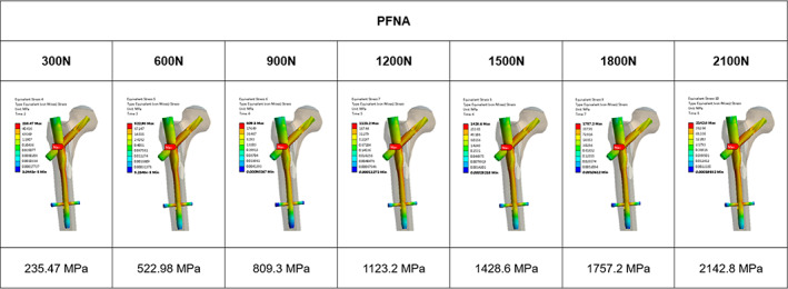
Von Mises stress in proximal femoral nail antirotation (PFNA) with respect to increasing loads. The maximum stress of the PFNA group appeared at the intersection of the spiral blade and the main nail, with a value of 2142.8 MPa under load of 2100 N
FIGURE 11.
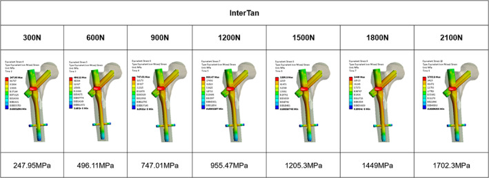
Von Mises stress in InterTan with respect to increasing loads. The maximum stress of the InterTan group was at the intersection of the interlocking twin nails and the main nail, and the value was 1702.38 MPa under load of 2100 N
FIGURE 12.
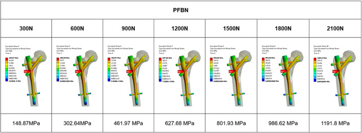
Von Mises stress in proximal femur bionic nail (PFBN) with respect to increasing loads. The maximum stress of the PFBN group was 1191.8 MPa at the intersection of the pressure nail and the main nail under load of 2100 N
FIGURE 13.
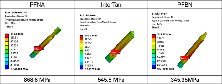
Von Mises stress in pull screw under a load of 2100 N. The maximum stress on the proximal femur bionic nail (PFBN) pression nail was 345.35 MPa, compared with 545.5 Mpa for InterTan interlocking twin nails and 868.6 MPa for the PFNA spiral blade
Discussion
New Understanding of the Mechanism of intertrochanteric Fracture and Bionic Internal Fixation
In the process of walking and going up and down the stairs, the human hip joint bears 2.3–2.8 times the weight of gravity 24 . The trabecular bone at the proximal end of the femur is distributed regularly and orderly, forming pressure trabecular bone and tension trabecula, which is similar to a lever system. The “lever‐balance‐reconstruction” theory proposed by Zhang D et al. believes that the structure of the proximal femur is similar to a lever system and the fulcrum of the lever is located near the center of the femoral head 14 . Due to the short moment of the medial femur, it bears higher compressive stress, and the moment on the outer side of the femur is longer, thus it bears smaller tensile stress. This asymmetry stress distribution results in thicker inner cortical bone and thinner outer cortex 25 . With aging, bone loss occurs, and the bone loss of the upper lateral cortex is more significant than that of the medial cortex. When falling sideways, a sharply increased impact force is often applied to the greater trochanter, while the lateral cortex experiences abnormally high compressive stress, which caused local buckling and fracture, and fracture of the proximal femur occurred 26 , 27 , 28 . Once a fracture occurs, the pressure trabecular bone and the tension bone trabecular structure are destroyed, that is, the physiological lever of the proximal femur is destroyed, and the compressive stress and the tensile stress are unbalanced, which means the lever structure is destroyed and the fulcrum disappears, and the femur cannot bear any weight anymore, which often results in the coxa vara. Therefore, the principle of treating intertrochanteric fractures is to reconstruct the fulcrum of the femur through the mechanical conduction system of internal fixation. The closer the fulcrum is to the physiological fulcrum, the more stable the postoperative fixation will be. Current treatment principles overemphasize the importance of the internal and external walls 29 , 30 . However the stability after fracture is essentially determined by the internal fixation system, and has nothing to do with the shape of the internal and external walls.
PFBN is designed based on the original patent of the triangular stable structure of Zhang Y et al and the lever balance reconstruction theory proposed by Zhang D et al. This fixation system is cleverly combined with tension nails and tension nails, which perfectly resists tensile stress and compressive stress during weight‐bearing after fracture operation, making the reconstructed fulcrum close to the anatomical fulcrum, with good stability, and theoretically suitable for all types of intertrochanteric fractures (Figures 10, 11, 12, 13).
Advantages of Finite Element Analysis
Finite element analysis is a widely accepted tool used in many industries and research activities, and computational modeling with finite element analysis (FEA) is an integral component of medical device design and development 31 . It is based on traditional biomechanics theory and transforms the research object into a model with a finite number of unit combinations, and the numerical simulation analysis is obtained. The results of the system's deformation, stress, strain distribution, etc. can be visually reflected the overall or partial biomechanical characteristics of the model, and various data can be modified in real time. Compared with the traditional experimental biomechanics test, it has the advantages of low cost, short cycle and high efficiency 32 . According to the AO/OTA intertrochanteric fracture classification updated in 2018, we choose A1.3 type intertrochanteric fracture to compare the characteristics of PFBN with PFNA and InterTan.
Maximal Stress and Displacement in FEA
From the stress and displacement distribution of the femur, it can be seen that each group of models produces different model deformations under the same load, but the maximum deformation is located at the point of stress at the top of the femoral head. After a fracture occurs between the trochanters, the original femoral levers and fulcrum disappears, the internal fixation will rebuild the mechanical conduction system of the femur. According to the above theory, we know that the stress of the cortical bone at the femoral head after the occurrence of bone is no longer uniformly conducted to the surrounding bones in physiological conditions, Instead, the stress is transmitted to the screw embedded in the femoral head. So there is a local stress concentration at the femoral head, and the maximum displacement is larger than that of the normal femur. Therefore, the tip of the femoral head will undergo a certain deformation after internal fixation of the fracture. The greater deformation means the more concentrated the corresponding local stress and higher risk in blade or screw cutout. Comparing the test results, the displacement value of the femoral head of the PFBN group was smaller than that of the PFNA group and the InterTan group, indicating that the stress of PFBN at the top of the femoral head was more dispersed, the deformation was smaller, and it was closer to the physiological condition.
From the maximum value of the stress distribution of the three groups of internal fixation, the structural stress of the PFNA and InterTan internal fixation is much higher than that of the PFBN internal fixation, and there is obvious stress concentration, while the PFBN stress is small and the distribution is more even than the other two groups. Due to the small stress, the risk of fatigue fracture of PFBN is lower than that of PFNA and InterTan, which is related to the structure of PFBN. PFBN moves the femoral fulcrum inward through the combination of pressure nail and tension nail, and realizes the anatomical reconstruction of the fulcrum. Through the cross combination of tension nail and pressure nail, it can effectively bear the compressive stress and tensile stress generated by the fracture during the postoperative load bearing. Compared with PFNA and InterTan, the tension nail shares a large part of the stress, reducing the stress at the junction of the main nail and the pressure nail in the femoral shaft, and avoiding the phenomenon of nail breakage caused by local stress concentration of the main nail. At the same time, the presence of tension nails disperses the compressive stress, reduces the burden of the pressure nails, and avoids the pressure nail breaking and internal fixation failure caused by the excessive load of the pressure nail. In addition, in terms of anti‐rotation, the main nail, pressure nail and tension nail are crossed, and the triangular surface anti‐rotation is realized on the coronal surface of the femoral head and neck, and the anti‐rotation is more reliable. In summary, its mechanical characteristics are closer to physiological conditions, and the bionic internal fixation of femoral tuberosity fractures is realized Table 1.
TABLE 1.
The number of nodes and elements of the model
| Normal femur | PFNA | INTERTAN | PFBN | |
|---|---|---|---|---|
| Nodes | 200368 | 310121 | 320147 | 336000 |
| Elements | 135209 | 204501 | 209569 | 219111 |
Abbreviations: PFBN, Proximal Femoral Bionic Nail; PFNA, Proximal Femoral Nail Antirotation.
Limitations of the Study
In this trial, the finite element method was used to compare the biomechanical differences between PFBN and PFNA and InterTan in the treatment of intertrochanteric fracture A1.3. The model and mechanics analysis method in the method are simplified to some extent, and the influence of muscles and ligaments on mechanics is not evaluated, which has limitations. At present, the biomechanical analysis and finite element analysis of the hip joint mainly study a single load in a certain posture, such as standing with two feet or one foot 33 . However, because the force of the hip joint under normal physiological conditions is not just a single load, it is actually a combination of many loads and changes with different postures and motion states of the body. It is extremely difficult to completely simulate the load of the femur in a physiological state. And there is still controversy about the loading of the hip joint, such as the number of muscle loads and the direction of the load in different states 34 . Therefore, most literature simplifies the hip joint force before proceeding to the next analysis and research, and we need further biomechanics research and clinical trials to draw more convincing conclusions.
Conclusion
Compared with PFNA and InterTan, PFBN is supported by more scientific theories and has better mechanical properties. PFBN has more advantages than traditional internal fixation systems in the treatment of femoral intertrochanteric fractures.
Acknowledgements
This work was financially supported by Natural Science Foundation of China (316781246, 31640045), and National Key Research and Development Project (2016YFC1101600). We would like to thank Medical Imaging Department and Information Department of Peking University Peoples' Hospital for providing files of CT images.
Yanhua Wang, Wei Chen and Lijia Zhang contributed equally to this work.
Disclosure: The authors declare that they have no conflicts of interest.
Contributor Information
Dianying Zhang, Email: zdy8016@163.com.
Yingze Zhang, Email: dryzzhang@126.com.
References
- 1. Veronese N, Maggi S. Epidemiology and social costs of hip fracture. Injury. 2018;49:1458–60. [DOI] [PubMed] [Google Scholar]
- 2. Brauer CA, Coca‐Perraillon M, Cutler DM. Incidence and mortality of hip fractures in the United States. JAMA. 2009;302:1573–9. [DOI] [PMC free article] [PubMed] [Google Scholar]
- 3. Panula J, Pihlajamäki H, Mattila VM. Mortality and cause of death in hip fracture patients aged 65 or older: a population‐based study. BMC Musculoskelet Disord. 2011;12:105. [DOI] [PMC free article] [PubMed] [Google Scholar]
- 4. Sheehan KJ, Sobolev B, Guy P. Mortality by timing of hip fracture surgery: factors and relationships at play. J Bone Joint Surg Am. 2017;99:e106. [DOI] [PubMed] [Google Scholar]
- 5. Tanner DA, Kloseck M, Crilly RG. Hip fracture types in men and women change differently with age. BMC Geriatr. 2010;10:12. [DOI] [PMC free article] [PubMed] [Google Scholar]
- 6. Queally JM, Harris E, Handoll HHG. Intramedullary nails for extracapsular hip fractures in adults. Cochrane Database Syst Rev. 2014;9:CD004961. [DOI] [PMC free article] [PubMed] [Google Scholar]
- 7. Brox WT, Roberts KC, Taksali S. The American Academy of Orthopaedic surgeons evidence‐based guideline on management of hip fractures in the elderly. J Bone Joint Surg Am. 2015;97:1196–9. [DOI] [PMC free article] [PubMed] [Google Scholar]
- 8. Andruszkow H, Frink M, Frömke C. Tip apex distance, hip screw placement, and neck shaft angle as potential risk factors for cut‐out failure of hip screws after surgical treatment of intertrochanteric fractures. Int Orthop. 2012;36:2347–54. [DOI] [PMC free article] [PubMed] [Google Scholar]
- 9. Kashigar A, Vincent A, Gunton MJ. Predictors of failure for cephalomedullary nailing of proximal femoral fractures. Bone Joint J. 2014;96‐B:1029–34. [DOI] [PubMed] [Google Scholar]
- 10. Buyukdogan K, Caglar O, Isik S. Risk factors for cut‐out of double lag screw fixation in proximal femoral fractures. Injury. 2017;48:414–8. [DOI] [PubMed] [Google Scholar]
- 11. Yu X, Wang H, Duan X. Intramedullary versus extramedullary internal fixation for unstable intertrochanteric fracture, a meta‐analysis. Acta Orthop Traumatol Turc. 2018;52:299–307. [DOI] [PMC free article] [PubMed] [Google Scholar]
- 12. Zhang Y, Chen W & Zhang Q A triangular‐supported intramedullary nail for femoral neck and intertrochanteric fractures. Patent CN201524132U. 2010.
- 13. Zhang D, Zhang X, Yu K. Attach importance to the relationship between fracture fixation and internal and external factors. Chin Electron J Shoulder Elbow Surg. 2018;6:81–4. [Google Scholar]
- 14. Zhang D, Yu K, Yang J. "Lever‐Fulcrum‐Balance" theory: a new understanding of the treatment of femoral intertrochanteric fractures. Chin J Trauma. 2020;36:647–51. [Google Scholar]
- 15. Zhang D, Yu K, Zhao X. Proximal femur bionic nail system with anti‐rotational and bionic reconstruction support. Patent CN209529309U. 2019.
- 16. Meinberg EG, Agel J, Roberts CS. Fracture and dislocation classification Compendium‐2018. J Orthop Trauma. 2018;32(Suppl 1):S1–S170. [DOI] [PubMed] [Google Scholar]
- 17. Kwak D‐K, Kim W‐H, Lee S‐J. Biomechanical comparison of three different intramedullary nails for fixation of unstable basicervical intertrochanteric fractures of the proximal femur: experimental studies. Biomed Res Int. 2018;2018:7618079. [DOI] [PMC free article] [PubMed] [Google Scholar]
- 18. Tucker SM, Wee H, Fox E. Parametric finite element analysis of intramedullary nail fixation of proximal femur fractures. J Orthop Res. 2019;37:2358–66. [DOI] [PubMed] [Google Scholar]
- 19. Speirs AD, Heller MO, Duda GN. Physiologically based boundary conditions in finite element modelling. J Biomech. 2007;40:2318–23. [DOI] [PubMed] [Google Scholar]
- 20. Eberle S, Gerber C, von Oldenburg G. A biomechanical evaluation of orthopaedic implants for hip fractures by finite element analysis and in‐vitro tests. Proc Inst Mech Eng H. 2010;224:1141–52. [DOI] [PubMed] [Google Scholar]
- 21. Inal S, Taspinar F, Gulbandilar E. Comparison of the biomechanical effects of pertrochanteric fixator and dynamic hip screw on an intertrochanteric femoral fracture using the finite element method. Int J Med Robot. 2015;11:95–103. [DOI] [PubMed] [Google Scholar]
- 22. Li J, Han L, Zhang H. Medial sustainable nail versus proximal femoral nail antirotation in treating AO/OTA 31‐A2.3 fractures: finite element analysis and biomechanical evaluation. Injury. 2019;50:648–56. [DOI] [PubMed] [Google Scholar]
- 23. Nie S‐B, Zhao Y‐P, Li J‐T. Medial support nail and proximal femoral nail antirotation in the treatment of reverse obliquity inter‐trochanteric fractures (Arbeitsgemeinschaft fur Osteosynthesfrogen/orthopedic trauma association 31‐A3.1): a finite‐element analysis. Chin Med J (Engl). 2020;133:2682–7. [DOI] [PMC free article] [PubMed] [Google Scholar]
- 24. Bergmann G, Deuretzbacher G, Heller M. Hip contact forces and gait patterns from routine activities. J Biomech. 2001;34:859–71. [DOI] [PubMed] [Google Scholar]
- 25. Lotz JC, Cheal EJ, Hayes WC. Stress distributions within the proximal femur during gait and falls: implications for osteoporotic fracture. Osteoporos Int. 1995;5:252–61. [DOI] [PubMed] [Google Scholar]
- 26. Mayhew PM, Thomas CD, Clement JG. Relation between age, femoral neck cortical stability, and hip fracture risk. Lancet. 2005;366:129–35. [DOI] [PubMed] [Google Scholar]
- 27. Turner CH. The biomechanics of hip fracture. Lancet. 2005;366:98–9. [DOI] [PubMed] [Google Scholar]
- 28. Abe S, Narra N, Nikander R. Exercise loading history and femoral neck strength in a sideways fall: a three‐dimensional finite element modeling study. Bone. 2016;92:9–17. [DOI] [PubMed] [Google Scholar]
- 29. Hsu CE, Shih CM, Wang CC. Lateral femoral wall thickness. A reliable predictor of post‐operative lateral wall fracture in intertrochanteric fractures. Bone Joint J. 2013;95‐B:1134–8. [DOI] [PubMed] [Google Scholar]
- 30. Nie B, Chen X, Li J. The medial femoral wall can play a more important role in unstable intertrochanteric fractures compared with lateral femoral wall: a biomechanical study. J Orthop Surg Res. 2017;12:197. [DOI] [PMC free article] [PubMed] [Google Scholar]
- 31. Goel VK, Nyman E. Computational modeling and finite element analysis. Spine (Phila Pa 1976). 2016;41(Suppl 7):S6–7. [DOI] [PubMed] [Google Scholar]
- 32. Huang H, Xiang C, Zeng C. Patient‐specific geometrical modeling of orthopedic structures with high efficiency and accuracy for finite element modeling and 3D printing. Australas Phys Eng Sci Med. 2015;38:743–53. [DOI] [PubMed] [Google Scholar]
- 33. Polgár K, Gill HS, Viceconti M. Strain distribution within the human femur due to physiological and simplified loading: finite element analysis using the muscle standardized femur model. Proc Inst Mech Eng H. 2003;217:173–89. [DOI] [PubMed] [Google Scholar]
- 34. Noda M, Nakamura Y, Adachi K. Dynamic finite element analysis of implants for femoral neck fractures simulating walking. J Orthop Surg (Hong Kong). 2018;26:2309499018777899. [DOI] [PubMed] [Google Scholar]


