

Abstract
Shot velocity is a crucial control parameter that is closely related to the shot peening effect. However, the traditional measurement method of shot velocity corresponding to air pressure is complicated and cannot reflect shot peening parameters (impingement angle, etc.). This study proposes a robust method to measure shot velocity by coupling simulations and experiments. By developing the measurement method presented in this paper, we can quickly and easily derive the linear shot velocity formulas corresponding to a series of impingement angles. The validity is verified and characterized by the arc height, surface roughness, residual stresses, and existing literature. The measured shot velocity can be applied to predict the effect of shot peening by the simulation method in aerospace and automotive industries. In addition, optimization of process parameters in terms of microstructure, microhardness, and mechanical properties is discussed in the context of experiments. This study shows that shot velocity is linearly related to shot peening pressure and is affected by impingement angles. The air pressure and exposure time should not be too large, and no microcracks should be created. The ultimate strength reaches the maximum, and the yield strength is significantly improved.
1. Introduction
Shot peening is a surface treatment process that improves the fatigue life and delays the crack propagation of metallic parts that are used in related industries. Conventional shot peening refers to the transfer of energy through solid media, such as stainless-steel balls, ceramic balls, and so forth, different from laser shot peening, high-pressure water shot peening, and ultrasonic shot peening. During this mature cold-working process, a large number of small shots are accelerated by high-pressure air to repeatedly impact the metal surface, causing plastic deformation, gradient microstructure changes,1,2 and hardening of the surface layer.3−5 The effectiveness and repeatability of the shot peening process are verified by using a simple and rapid standard test: the Almen intensity test.6 It is well known that the Almen intensity is proportional to the shot kinetic energy.7 Therefore, if one were able to accurately measure the shot velocity, they would also be able to determine the Almen intensity. Many researchers have experimentally studied the effect of air pressure on the Almen intensity.8−12 However, the Almen intensity is ensured by air pressure in actual shot peening, instead of shot velocity. With the development of numerical tools and theoretical approaches, some investigators have performed a lot of studies on the shot peening process based on shot velocity.13−17 For example, discrete element models were proposed to simulate a large number of shots.18 Jebahi et al.19 and Wang et al.6 presented the coupling model of discrete elements and finite elements (DEM–FEM) and used elastic theory to calculate the arc height of the Almen strip with different shot velocities. These analytical models have been proposed to relate the deformation of the strip to shot velocity and other parameters.7,20 For both the simulation method and the theoretical analysis method, shot velocity is measured and determined in priority. It is important to accurately measure the shot velocity, as this is related to the accuracy of the simulation and theoretical analysis methods.
The most obvious and traditional method is to measure the shot velocity directly using a specialized measurement device such as a high-speed camera.9,21,22 However, specialized measurement devices for shot velocity can be used to measure the velocities of a few shots rather than all those involved in the actual process. A lot of experiments showed that the shot velocity summarized by Klemenz et al.23 through a semiexperiential formula is unfortunately not applicable to all blasting machines. Because of the impingement angle, moving velocity of the nozzle, blast nozzle style, and inner diameter, some of the shots inevitably collide with each other, as shown in Figure 1a. In fact, what the shot velocity data demonstrate is that the portions of the operating range for some nozzles are unstable.24,25Figure 1b illustrates the detailed distribution of the shot velocities at the target’s surface as reported by Tu et al.26 and Hong et al.27 These direct measurement methods of shot velocity cannot accurately reflect shot peening parameters (impingement angle, etc.) and shot–shot interactions in the actual process.
Figure 1.

Distribution of shot velocities in the actual process. (a) Distribution of velocities is related to shot peening parameters. (b) Schematic example of an impingement velocity distribution calculated using EDEM software. In this example, approximately 30% of the shots impact the surface with their initial velocity (impingement angle α = 67.5°). Reprinted (adapted or reprinted in part) with permission from Gariépy et al.25 Copyright 2017 The Authors.
In addition, other researchers tend to use the indirect method to measure the shot velocity. For example, Nordin et al.28 introduced an experimental comparison method to obtain the shot velocity by indent size comparison. However, this method is limited to a single small shot with a low coverage. Moreover, there is a kinematic model of shots based on the simulation method to measure the shot velocity as reported by Liu et al.29 However, these indirect measurement methods still cannot reflect shot peening parameters (impingement angle, etc.) or shot–shot interactions, either. At present, it is concluded that the traditional measurement method of shot velocity is not universal due to the differences in machines and cannot reflect shot peening parameters (impingement angle, etc.) and collision between shots in actual shot peening.
Indeed, we all know that the measurement of shot velocity is ultimately needed for accurate simulation and theoretical analysis. It is impossible to obtain the real velocity distribution of every shot involved by the existing measurement methods. Therefore, Jebahi et al.19 and Wang et al.30 proposed equivalent shot velocity, in which each shot involved in the shot peening process has the same initial velocity, instead of the actual velocity distribution of all shots involved in the actual process.
Since the shot velocity of conventional shot peening is usually not high, the macro- and microchanges of materials are not as obvious as those of severe shot peening, so the relevant research is not sufficient. At present, the interest in shot velocity on the shot peening effect is mainly aimed at the severe shot peening process. Since the shot velocity of conventional shot peening is usually lower, the macro- and microchanges of materials are not as obvious as those of severe shot peening, so the relevant research of shot velocity measurement is not sufficient. By reviewing the literature, we see that a number of studies have found that Almen intensity is linearly proportional to the shot velocity or air pressure.12,21,31,32 Inspired by remarkable earlier works, a robust method coupling the Almen intensity numerical method and Almen intensity experiment has been developed in the paper, in which the Almen intensity is used to bridge the equivalent shot velocity and air pressure. We believed that shot velocity is directly proportional to air pressure for a given blast nozzle style, inner diameter, and shot peening parameters. In a word, equivalent shot velocity is not only related to air pressure but also affected by the shot peening parameters (impingement angle, etc.). The primary difference between this present study and the previous work30 is that intermediate Almen intensity is a widely accepted standard test method for evaluating the effects of the peening process, and the intermediate surface roughness is a local mesoscopic scale measurement that is less accurate than the Almen intensity, depending on the treated material and peening time (the coverage) without considering the shot peening parameters.
The numerical simulation method obtains the induced stress profile, arc height, and Almen intensity under the given simulation parameters such as shot velocity and shot number. The higher the shot velocity, the higher the arc height and Almen intensity. Then, the arc height and intensity values under different air pressures were obtained by the experimental method. Almen intensity is used to bridge the shot velocity and air pressure. The advantages of the robust measurement method for shot velocity presented in this paper are that the linear relationship is efficient and reliable. We can use the equivalent shot velocity, in which each shot involved in the shot peening process has the same initial velocity to simulate the shot peening process, instead of the actual velocity distribution of all shots involved. The shot peening process introduces the residual compressive stress on the surface to significantly improve the fatigue life. The microhardness increases on the surface relative to the undeformed layers on the sample interior by increasing the shot velocity. With higher air pressure, more grains are refined, namely, the thickness of the hardened surface layer increases. All treated strips present an improvement in tensile mechanical properties in comparison with the untreated strips. The air pressure and exposure time should not be too large, and no microcracks should be created. The ultimate strength reaches the maximum, and the yield strength is significantly improved. In summary, the new method of shot velocity measurement proposed in this paper, which can accurately predict the shot peening effect (arc height, surface roughness, residual stresses, microhardness, gradient microstructure, mechanical properties, etc.) and be further extended to shape the desired contour, presents a major step toward precise quantitative shot peening technology.
2. Current Approach for Shot Velocity Measurements
2.1. Overall Introduction
In the current study, the indirect measurement strategy reported by Wang et al.33 was applied to obtain the shot velocity by the intermediate Almen intensity test. Figure 2 displays the implementation of this robust shot velocity measurement method. At first, the Almen intensity is linearly proportional to the air pressure or the shot velocity obtained by the test method and simulation method, which is displayed in eqs 1 and 2. It should be pointed out that the shot flow cannot be set to 0. To ensure that the nozzle is not blocked, the actual air pressure cannot start from 0. Second, by applying eqs 1 and 2, the shot velocity is directly related to the air pressure through the intermediate Almen intensity (AI, mm), as displayed in eq 3. Finally, the shot velocityV is measured by the approximate linear relationship, which is displayed in eq 4.
| 1 |
| 2 |
| 3 |
| 4 |
where a is equal to a1over a2, and bis equal to  overa2.
Figure 2.

A robust method to measure the shot velocity.
2.2. Experimental Procedure for Determining the Almen Intensity
Figure 3a shows the experimental Almen shot peening intensity standard experimental method.10 The arc heights of the Almen strips corresponding to different numbers of passes are measured using a specialized Almen gauge. These arc heights are plotted as a function of their number of passes; this is called the saturation curve. The saturation point is defined as the number of passes for which doubling the number of passes increases the arc height by 10%. Then, Almen intensity is the arc height value corresponding to the saturation point, as shown in Figure 3b. To obtain the saturation point, the arc height value data are fit with the following equations
| 5 |
whereAh is the arc height by the experimental method, T is the number of passes, andA1, B1, and y1 are fitting parameters.
Figure 3.

Almen intensity test process. (a) The Almen strip is fixed on its holder. After a certain number of passes during which the strips bend and extend, the strip is removed from the Almen strip holder. The arc height is obtained by the specialized Almen gauge and (b) the Almen intensity is the arc height corresponding to the saturation point in the saturation curve.
The number of passes at saturation, Ts, is defined below
| 6 |
Here,  is the arc height corresponding to the
saturation point (Almen intensity).
is the arc height corresponding to the
saturation point (Almen intensity).
2.2.1. Equipment and Process
The Almen strip intensity method is the most commonly used standard experimental method to quantitatively evaluate shot peening effects in industrial practice. In the Almen intensity experiments, the test strategy presented by Wang et al.6 was applied to obtain the Almen intensity. The most common Almen strip of type A with a thickness of 1.29 mm was selected as the research object in all experiments, as schematically displayed in Figure 4a. Because of the absence of self-equilibrating force and moment, the strips bend toward the peening direction.34 To measure the arc height, the Almen strips are attached to the top of four small cylinders by magnets to ensure no tilting. It is worth noting that the Almen gauge measures the total arc heights between specific dimensions of the strip: 31.75 mm in the longitudinal direction and 15.87 mm in the transverse direction.12Figure 4b shows that the relationship between the curvature radius R and Ah can be calculated by geometrical analysis, which is expressed by eq 7
| 7 |
where L refers to the length of the span (Hu et al.35).
Figure 4.

Equipment and materials. (a) Type A Almen strip. (b) Almen gauge and arc height measurement.
2.3. Modeling Approach for Almen Intensity
2.3.1. Improved DEM–FE Coupling Model
At present, there are two methods to simulate the Almen intensity test: representative elementary volumes19,36 and the direct simulation method of real shot numbers.6 In this study, the simulation strategy presented by Wang et al.33 was applied to simulate realistic peening data from the Almen intensity test. A specific target mesh, with dimensions of 1.2 × 1.2 × 0.5 mm, was selected as a representative volume to study the induced and residual stress and surface roughness, as shown in Figure 5a. All side faces of the target mesh are surrounded by so-called half-infinite elements that prevent the reflection of elastic shear waves.37,38 The mesh size of the target is set similar to those used by Jebahi et al.19 and Wang et al.30 A robust DEM–FEM coupled model was used, which takes the shot–shot collisions and impingement angles into account.
Figure 5.

Shot peening model with shot–shot interactions. (a) Target mesh. (b) Robust DEM–FEM recoupled model with different impingement angles.
The mechanical properties and the Johnson–Cook constants of SAE 1070 and shots of type S230 are presented in Table 1.39 To simulate these randomly distributed shots, a large number of random shots are modeled by using the PD3D element with isotropic elastic behavior, as displayed in Figure 6. The S230 shots used in the Almen intensity test were modeled as spherical bodies by using the elastic properties given in Table 1. Shot velocity used in simulation was defined as the initial velocity for all the shots involved. The impingement angles were set to 90 and 45° corresponding to the impingement angle of shot peening parameters in the actual Almen intensity test. The isotropic Coulomb friction coefficient of μ = 0.2 was used to model the shot–shot collisions and shot–target interactions. For practical purposes, 98% coverage is usually treated as 100% coverage. In the present study, the coverage evolution reported by Wang et al.6 was applied to calculate the number of shots.
Table 1. Mechanical Properties and Johnson–Cook Constants of the Almen Strip and S230 Shot; Reprinted (Adapted or Reprinted in Part) with Permission from Wang et al.6 Copyright 2020 The Authors.
| mechanical
properties |
Johnson-Cook constants |
||||||||
|---|---|---|---|---|---|---|---|---|---|
| parts | material | Young’s modulus E(GPa) | poisson’s ratio ν | density ρ (kg/m3) | A | B | C | n | m |
| shot | stainless steel | 210 | 0.3 | 7850 | / | / | / | ||
| Almen strip | SAE 1070 | 205 | 0.29 | 7800 | 1048 | 600.8 | 0.0134 | 0.234 | 0 |
Figure 6.

Python program frame for random coordinates of a lot of shots in the simulation.
2.3.2. Deformation and Almen Intensity
In the present study, the theoretically calculated strategy presented in Wang, Li19,29 was used to calculate the Almen intensity. The compressive force Fx and the bending moment Mycan be calculated from the peening-induced stress, σind, as
| 8 |
| 9 |
where h is the Almen strip thickness and z is aligned along the strip thickness and originates at the treated surface. The deformation of the Almen strips can be obtained from the bending moment (My) by equilibrating the residual stress field and arc height (hl),40 as given by eq 10
| 10 |
whereEI is the strip’s bending stiffness after shot peening and L, b, and h are the strip length, width, and thickness, respectively. The total arc height Ah can be evaluated as the sum of arc heights from the two curvatures, which is expressed by eq 11
| 11 |
where hl is the longitudinal arc height andhtis the corresponding transverse arc height. To obtain the saturation point in the saturation curve, the calculation results from the numerical method are fitted with
| 12 |
where N is the number of all shots involved in the model, and A2, B2, andC2 are fitting parameters. The number of shots corresponding to saturation point, Ns, is defined below
| 13 |
The average stresses over the whole thickness direction were obtained, as shown in Figure 7a. The induced stress σind and the residual stress σres with different shot velocities are shown in Figure 7b. Through the robust coupled model proposed in this paper, shot–shot collisions and transverse deformation are considered, which is closer to the real Almen intensity test.34
Figure 7.

Stress profile σind determined by the numerical method. (a) The whole thickness direction at different stages of shot peening is extracted layer by layer. (b) Stress profile evolution from induced stress to residual stress, when the shot velocity is 30 and 50 m/s and the number of shots is 200.
3. Results
In this study, we believed that the shot velocity is directly proportional to the air pressure for a given blast nozzle style, inner diameter, and shot peening parameters (impingement angle, etc.). The relationship between the shot velocity and air pressure is established by the bridge: Almen intensity (AI).
3.1. Experimental Results with Different Impingement Angles
With shot peening modifying the target’s surface, the morphology and microstructure on the surface layer change.41,42 Plastic deformation on the top surface layer of the Almen strip increases with the number of passes, as shown in Figure 8a. It can be observed that the number of the indentations increases with increasing exposure time. Figure 8b shows that the Almen intensity values measured by the experimental method increased as the air pressure was increased from 1.0 to 3.0 bar. The linear relationship between AI and air pressure P is fitted by regression equations
| 14 |
| 15 |
when α, the impingement angle, was 90°, the goodness of fit was approximately 0.94 and when the impingement angle, α, was 45°, the goodness of fit was approximately 0.95.
Figure 8.

Almen intensity with different air pressures and impingement angles of the Almen strip. (a) Surface topography by optical microscopy, when the moving speed of the nozzle is 800 mm/min, shot peening times are 1 and 8, and the surface morphology is 80 times larger under the microscope. (b) Linear relationship between the air pressure and the Almen intensity with different air pressures and impingement angles, when the impact angles are 45 and 90°.
3.2. Simulation Results with Different Impingement Angles
By applying eq 11 to the results of the different simulations presented in Figure 8, the saturation curves associated with different velocities and the impingement angles α = 45°,90° can be obtained. A comparison between the robust numerical method and existing control curves for α = 90° is given in Figure 9a. The saturation curve plotted by the simulation method proposed in this work is obviously greater than that reported by Jebahi et al.19 This can be explained by the fact that the transverse bending is not small and should not be neglected. Figure 9b shows the saturation curves for obtaining the Almen intensity under different shot velocities, corresponding to different impingement angles. The linear relationship between AI and V (V ranges from 20 to 55 m/s) is expressed by the following regression equations, respectively
| 16 |
| 17 |
when α, the impingement angle, was 90°, the goodness of fit was approximately 0.95; when α was 45°, the goodness of fit was approximately 0.96.
Figure 9.

Almen intensity values obtained by different methods are compared. (a) Saturation curves of the Almen strip, corresponding to the impingement angle α = 90° and shot velocity V = 55 m/s. (b) Relationship between shot velocity and Almen intensity at different impingement angles.
3.3. Shot Velocity Measurement
The shot velocity is related to the air pressure by the intermediate Almen intensity according to Section 2.1. The shot velocity V is measured by the following regression equations
| 18 |
| 19 |
Here, it is worth noting that Formulas 18 and 19 are derived from the 90 and 45° impacts, respectively. The two formulas are in close agreement when the effect of the impingement angle on the measured velocity is ignored. We derive the formula between Vand P from the method of using the average data. Finally, the average linear relationship between the V and P is presented by the following regression equation
| 20 |
As the impingement angle α increases, this difference may cause an increasing number of bouncing shots which will influence the shot that has not yet impacted the metal surface by affecting the impingement angle and or reducing the impact velocity.27 Thus, the shot–shot interactions considered in this study reduce the kinetic energy transferred from the shot stream to the target surface. In conclusion, the impingement angle is considered in the robust method. However, the shot may drift away as the air pressure P increases, as shown in Figure 10. This can be explained by the fact that the effects of shot–shot interactions become more significant at high-air pressures.
Figure 10.

Shot velocity measured by this method at 45 and 90° impact angles was compared with the shot velocity in the literature, when the shot type is S230 and the shot material is stainless steel.
4. Discussion
The 7075 aluminum alloy and AISI 4340 steel are used for engineering applications in the aerospace and automobile industries. Thus, 7075 aluminum alloy and AISI 4340 steel were selected as the study objects to verify the reliability of the shot velocity formula and explore the process parameters in terms of microstructure, microhardness, and mechanical properties. The mechanical properties and the Johnson–Cook constants of 7075 aluminum alloy are given in Table 2.
Table 2. Mechanical Properties and Johnson–Cook Constants of 7075 Aluminum Alloy (Taken from Sheng et al.43).
| mechanical
properties |
Johnson-Cook constants |
|||||||
|---|---|---|---|---|---|---|---|---|
| material | young’s modulus E(GPa) | poisson’s ratio ν | density ρ (kg/m3) | A | B | C | n | m |
| Al7075-T7651 | 71.7 | 0.3 | 2810 | 527 | 629 | 0.017 | 0.71 | 1.61 |
4.1. Arc Height Verification of Al7075-T7651
Shot velocities measured by this paper were used as the initial velocity in the simulation model. For S230 steel shot with a diameter of 0.58 mm and a mass flow of 6.0 kg/min, the arc heights of the Almen-sized 7075 strip were measured by an Almen gauge, as shown in Figure 11a, where the air pressure P values were equal to 2.0, 2.5, and 3.0 bar. The arc heights of Almen-sized 7075 strips were calculated by the numerical method and elasticity theory, where shot velocities V were equal to 36, 41, and 46 m/s. Figure 11b shows that these arc height curves are in close agreement, corresponding to the impingement angle α = 90°; however, the arc height values obtained by the elasticity theory are always less than those measured by the experimental method. Similar results were reported by Jebahi et al.19
Figure 11.

Arc height verification of Al7075 strips, when the shot type is S230 and the moving speed of the nozzle is 800 mm/min. (a) Deformation of the Al7075 strip after shot peening. (b) Arc height comparison of the two methods.
4.2. Residual Stress and Surface Roughness Verification of Al7075
The residual compressive stress on the surface hinders the initiation and propagation of internal cracks within a metal. Hence, the shot peening process improves the resistance of a metal to fatigue, corrosion, and stress corrosion cracking. To further verify the correctness of the measured shot velocity and whether the microstructure changed, the residual stress values obtained by the numerical method were compared with the experimentally determined values. The X-ray diffraction (XRD) method based on lattice strains was employed to measure the residual stress profile with different parameters. The measurements were carried out at the Southwest Jiaotong University with their equipment. The residual stresses at z = 0, 0.02, 0.04, 0.06, 0.08, 0.1, 0.12, and 0.15 mm were measured after electropolishing circular areas having a 4.0 mm diameter (see Figure 12a). After electropolishing, it is worth noting that the surfaces were more uniform, and the errors in residual stress were reduced. The residual compressive stress profile is assumed to be only a function of depth into the surface. After each depth measurement, the residual stress was corrected for both depth averaging and material removal. Comparing the results, we found that the distribution trends of the compressive residual stresses measured by the two methods were consistent, as illustrated in Figure 12a.
Figure 12.

Measurement method verification of the Al7075 samples, when the shot type is S230 and the moving speed of the nozzle is 800 mm/min. (a) Deformation of the Al7075 strip after shot peening. (a) The robust method was verified by the residual stress; Vis equal to 38 m/s, corresponding to P being equal to 2.5 bar. (b) The microstructures at the surface and the robust method were verified by the surface roughness with different shot velocities (corresponding to air pressure).
The 3D morphologies near the surface were observed by optical microscopy to evaluate the effect of shot peening on the microstructure. Surface roughness is another reliable and available index. Figure 12b displays the 3D morphologies of the target surface and surface roughness values with different shot velocities (corresponding to the air pressure). The surface roughness results and the distribution trend of Ra found in this study were consistent with those on another method that were reported in the literature.30
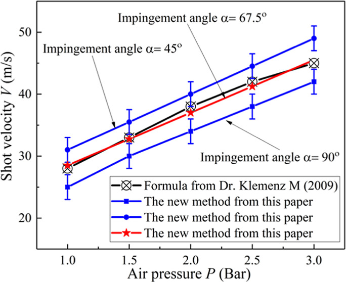
4.3. Comparison of the Robust Method with Other Methods
Compared with the semiexperiential formula introduced by Klemenz et al.23 and the equivalent velocity method proposed by Wang et al.,30 we found that the predicted shot velocity determined in this study is generally consistent with the values determined by other methods, especially at relatively low velocities. The shot velocities calculated by Klemenz et al.23 were between those calculated by formula 19 (impingement angle α = 90°) and formula 20 (impingement angle α = 45°). The shot velocity at an impingement angle α = 67.5°, which is themed point of the two angles, has little difference between the two measuring shot velocity methods, and a similar curve profile is shown in Figure 13a. It is interesting to determine the shot velocity more accurately at this angle by this robust method. Figure 13b shows that it is necessary to consider the impingement angle in the actual shot peening process. This figure clearly shows that for all impingement angles smaller than 90° the shot velocities increase linearly with air pressure. When the impingement angle is 45°, the equivalent shot velocity value is the largest, and it changes most with the air pressure. We can derive the linear mathematical relationship between the shot velocity and the pressure corresponding to a series of impact angles. By developing the robust measurement shot velocity method presented in this paper, we can relate the shot velocity measurements to the impingement angle of actual shot peening parameters. Traditional methods fail to take this into account.
Figure 13.

Comparison of the robust method with other methods, when the shot type is S230 and the diameter of the projectile is 0.58 mm. (a) The robust method has a similar trend to other methods. (b) measured by the robust method corresponding to some series of impingement angles.
4.4. Effect of the Peening Parameters on Microstructure and Mechanical Properties
The peening effect is usually controlled by two parameters: Almen (peening) intensity and peening coverage. For the other given parameters, the Almen intensity is determined by the air pressure and impingement angle, and the coverage is related to the nozzle movement velocity. In this study, therefore, we selected the air pressure, impingement angle, and nozzle movement velocity for parameterized analysis.
4.4.1. Microstructure and Microhardness of Al7075-T7651
In addition to residual compressive stress on the surface, the shot peening process does introduce significant improvement of fatigue life by inducing grain refinement in the surface hardened layer. Figure 14 shows the XRD patterns of the surface layer in Al7075-T7651 before and after shot peening. Comparing with the original Al7075-T7651 before shot peening, it can be clearly seen from Figure 14 that the Bragg diffraction peaks of Al7075-T7651 after shot peening are obviously broad. The greater the shot velocity (air pressure) and the slower the nozzle velocity, the wider the Bragg diffraction peaks, which are mainly contributed from the factors of grain refinement and an increase in the atomic-level microstrain.
Figure 14.

XRD patterns of the Al7075 specimen surface layers under different process parameters: (a) The nozzle moving velocity is 800 mm/min and the pressures are 1.0, 2.5, and 4.0 bar. (b) The nozzle moving velocity is 200 mm/min and the pressures are 1.0, 2.5, and 4.0 bar.
The average crystallite sizes are calculated from the full width at half maximum intensity (FWHM) of Bragg diffraction peaks according to the Scherrer–Wilson method. Figure 15 shows that the FWHM decreases with depth at different shot peening pressures. The average crystallite sizes demonstrate that the degree of grain refinement increases with an increase in the air pressure and a decrease in the nozzle velocity, as shown in Figure 15b. The average grain size reduction distribution results confirm that the refinement of the gradient microstructure was the result of plastic deformation and dislocation density induced by high-speed shots impacting the specimen surface, in which the surface grains absorb most of the energy of impact. It can be understood that changing the microstructure by shot peening can cause lattice distortions that introduce residual compressive stress and FWHM.
Figure 15.

Microstructure of the Al7075 specimen surface layers under different process parameters: (a) FWHM decreases with depth at different shot peening pressures, and the pressures are 1.0, 1.5, and 2.0 bar. (b) Average crystallite sizes of the surface layer under different shot peening parameters.
The microhardness distribution is in good agreement with the FWHM results, which depend on the domain size of the metal.44 Hence, the microstructure near the treated surface is also indirectly described by the microhardness distribution. The specimens with fine shot peening showed higher microhardness than those of specimens without treated process, while the microhardness gradually decreased with increasing depth from the surface. The microhardness increases at the target’s surface by 17.2–21.5% relative to the base metal by raising the air pressure from 1.0 to 2.0 bar, as shown in Figure 16. Microhardness distribution curve of shot velocity 26 m/s (air pressure, 1.0 bar; impingement angle α = 90°) is much gentler than that of shot velocity 36 m/s (air pressure, 2.0 bar; impingement angle α = 90°), shot velocity 30 m/s (air pressure, 1.5 bar; impingement angle α = 90°), and shot velocity 40 m/s (air pressure, 2.0 bar; impingement angle α = 45°). This implies that with a higher air pressure, more grains were refined, namely, the surface-hardened layer thickens, and the thickness of the surface-hardened layer is approximately 0.125 mm, which increases with the air pressure of the shot peening parameters. Table 3 shows the shot peening parameters and treated material Al7075-T7651 for microhardness.
Figure 16.

Microhardness distribution with increasing depth at different air pressures and impact angles.
Table 3. Shot Peening Parameters and Al7075-T7651 Specimens for Microhardness.
| mechanical
properties |
Johnson-Cook constants |
|||||||
|---|---|---|---|---|---|---|---|---|
| material | young’s modulus E(GPa) | poisson’s ratio ν | density ρ (kg/m3) | A | B | C | n | m |
| Al7075-T7651 | 71.7 | 0.3 | 2810 | 527 | 629 | 0.017 | 0.71 | 1.61 |
4.4.2. Tensile Properties of AISI 4340 Steel
Improved mechanical properties by the peening process can enhance the fatigue life and delay the crack propagation of the metallic parts. In addition to the microstructure and microhardness properties described in the previous section, the tensile behavior after surface treatment can describe the improved mechanical properties. High-strength AISI 4340 steel is one of the most widely used materials in the aerospace and automotive industries. Its application is mainly in gears, shafts, and aircraft landing gears, where fatigue behavior is always the first design consideration. AISI 4340 steel is the subject of the materials studied in this section. Table 4 shows the shot peening parameters of the AISI 4340 steel tension specimens. Figure 17a displays the facility setup of the mechanical test (MTS793) and geometry of the tensile specimens. Figure 17b shows the specimens treated by different shot peening parameters and no shot peening.
Table 4. Shot Peening Parameters and AISI 4340 Steel Tension Specimens.
| shot
peening parameters |
||||
|---|---|---|---|---|
| case | material | thickness (mm) | air pressure (bar) | nozzle movement velocity (mm/min) |
| 1 | AISI-4340 | 1.0 | 0.0 | 0.0 |
| 2 | AISI-4340 | 1.0 | 1.0 | 500.0 |
| 3 | AISI-4340 | 1.0 | 1.0 | 250.0 |
| 4 | AISI-4340 | 1.0 | 1.0 | 125.0 |
| 5 | AISI-4340 | 1.0 | 2.0 | 500.0 |
| 6 | AISI-4340 | 1.0 | 2.0 | 250.0 |
| 7 | AISI-4340 | 1.0 | 2.0 | 125.0 |
| 8 | AISI-4340 | 1.0 | 3.0 | 500.0 |
| 9 | AISI-4340 | 1.0 | 3.0 | 250.0 |
| 10 | AISI-4340 | 1.0 | 3.0 | 125.0 |
Figure 17.

Tensile property experiment of AISI 4340 steel. (a) Facility setup of the mechanical test geometry of the specimens. (b) Macromorphologies of the shot peened specimens with different parameters after breaking.
To display their specific impacts on tensile behavior, the true stress–strain curves for various shot peening parameters are shown in Figure 18. It can be seen that higher air pressures led to higher yields and ultimate stress values, where the higher shot velocity causes loss of subsequent ductility. Similarly, a lower nozzle movement velocity led to higher yield and ultimate stress values, whereas a lower nozzle movement velocity causes a loss of subsequent ductility. More details about the yield and ultimate stress values under different shot peening parameters are shown in Figure 18a–e. This occurred because the gradient microstructure (refinement grains) at the surface resulted in increasing yield stress, and the finer grains caused lower ductility. Refining the grain size of metals generally elevates their strength, but the ductility decreases drastically since refined grains retain less space to accommodate dislocations. It is interesting to note that even though greater nozzle movement velocity causes a reduction in yield stress, it hardly influences the ultimate strength, and it tends to prevent ductility loss, as shown in Figure 18f. With the goal of strength-plastic matching, these are the best shot peening parameters. That is, the air pressure and exposure time should not be too large, and no microcracks are caused; meanwhile, the ultimate strength reaches the maximum, and the yield strength is significantly improved.
Figure 18.

Stress–strain curves of the AISI-4340 specimens under different nozzle moving velocities, when the shot type is S230 and the diameter of the projectile is 0.58 mm: (a) shot peening pressure is 1.0 bar and different nozzle movement velocities; (b) shot peening pressure is 2.0 bar and different nozzle movement velocities; (c) shot peening pressure is 3.0 bar and different nozzle movement velocities; (d) nozzle movement velocity is 250.0 mm/min and different shot peening pressures; (e) nozzle moving velocity is 125.0 mm/min and different shot peening pressures; (f) yield stress and ultimate stress values under different shot peening process parameters.
Scanning electron microscopy (SEM) observations were performed to characterize the microstructure evolution and deformation mechanism of AISI-4340 alloy after shot peening. Figure 18 represents a cross-sectional SEM observation with different shot peening parameters in high- and low-magnification images. Figure 19a shows the fracture morphology without shot peening. Figure 19c–f displays the fracture morphology with different shot peening parameters. From the overall observation of Figure 18, a distinct region with obvious boundaries separate from the inner material is easily recognized on the top surface. The reason is that the repeated impacts on the surface and folding of the deformed regions led to the formation of such regions.38Figure 19c,e shows that the surface fine-grained layer is approximately 300 and 200 μm with shot peening pressures of 3.0 and 1.0 bar, respectively. Furthermore, the high-magnification images show that there are smaller ligaments generated in the fine-grained surface layer. As the air pressure increases, the proportion of the ligaments that can be observed in the fracture of the cross-sectional observation decreases, which may be the cause of the decreases in the elongations of the specimens..
Figure 19.

Fracture morphologies of the AISI-4340 alloy structural steel specimen at high and low magnifications when the shot type is S230 and the diameter of the projectile is 0.58 mm: (a,b) fracture morphologies without shot peening, (c,d) fracture morphologies with a shot peening pressure of 3.0 bar and a nozzle movement velocity of 125 mm/min, and (e,f) fracture morphologies with a shot peening pressure of 1.0 bar and a nozzle movement velocity of 125 mm/min.
5. Conclusions
The effects of shot peening experiments, shot peening simulations, and their combination considering both sequences on microstructure, microhardness, arc height, residual compressive stress, surface roughness, and mechanical properties of metal alloy were investigated. Due to some limitations of the traditional measurement methods, this study developed a robust method for measuring the shot velocity. We derived a linear mathematical relationship between the shot velocity and the pressure corresponding to a series of impingement angles. Finally, the effects of the process parameters on the target’s surface (depth) composition, arc height, surface roughness, residual stresses, microhardness, gradient microstructure, and mechanical properties were discussed. The main findings of this work can be summarized as follows:
-
1
To measure the shot velocity more accurately, it is worth noting that it is necessary to consider shot peening parameters (impingement angle, etc.). The robust method proposed in this paper takes the impingement angle into account, which is consistent with the impingement angle used in actual shot peening. By developing the robust measurement shot velocity method presented in this paper, we can quickly and easily derive the linear shot velocity formulas corresponding to a series of impingement angles.
-
2
The residual compressive stress on the surface hinders the initiation and propagation of internal cracks within a metal. The greater the shot velocity (corresponding to the air pressure), the greater the depth of residual stress and the greater the maximum residual compressive stress, which improves the effect on fatigue life. In addition to residual compressive stress on the surface, the shot peening process does introduce significant improvement on fatigue life by changing the microstructure and inducing grain refinement in the surface hardened layer. The microhardness increases at the surface relative to the undeformed layers in the sample interior by raising the shot velocity. With higher air pressure, more grains are refined, namely, the surface hardened layer thickness.
-
3
All treated strips show an improvement of mechanical tensile properties in comparison with the untreated strips. This occurs because the gradient microstructure (refined grains) at the surface results in increasing yield stress, and the finer grains cause lower ductility. It was concluded that a higher air pressure and less nozzle movement velocity lead to higher yield and ultimate stress, where they also cause loss of subsequent ductility. In summary, the air pressure and exposure time should not be too large, and no microcracks should be created. The ultimate strength reaches the maximum, and the yield strength is significantly improved.
Acknowledgments
We would like to thank Southwest Jiaotong University for providing the opportunity and necessary help to perform this study.
The authors declare no competing financial interest.
References
- Unal O.; Cahit Karaoglanli A.; Varol R.; Kobayashi A. Microstructure evolution and mechanical behavior of severe shot peened commercially pure titanium. Vacuum 2014, 110, 202–206. 10.1016/j.vacuum.2014.08.004. [DOI] [Google Scholar]
- Liu H.; Chen M.; Wang L.; Zhan K.; Ji V.; Jiang C. Investigation on microstructure and properties of Al18B4O33 whisker reinforced Al Mg Si matrix composite after shot peening. Vacuum 2019, 160, 303–310. 10.1016/j.vacuum.2018.11.031. [DOI] [Google Scholar]
- Garcia-Martin J.; González-Fernández R.; Calleja-Saenz B.; Ferreño-Blanco D. Measurement of hardness increase for shot-peened austenitic TX304HB stainless steel tubes with electromagnetic Non-Destructive testing. Measurement 2020, 149, 106925. 10.1016/j.measurement.2019.106925. [DOI] [Google Scholar]
- Unal O.; Maleki E.; Kocabas I.; Yilmaz H.; Husem F. Investigation of nanostructured surface layer of severe shot peened AISI 1045 steel via response surface methodology. Measurement 2019, 148, 106960. 10.1016/j.measurement.2019.106960. [DOI] [Google Scholar]
- Zhao J.; Kan Q.; Zhou L.; Kang G.; Fan H.; Zhang X. Deformation mechanisms based constitutive modelling and strength-ductility mapping of gradient nano-grained materials. Mater. Sci. Eng., A 2019, 742, 400–408. 10.1016/j.msea.2018.10.096. [DOI] [Google Scholar]
- Wang C.; Li W.; Jiang J.; Chao X.; Zeng W.; Xu J.; Yang J. An Improved Approach to Direct Simulation of an Actual Almen Shot Peening Intensity Test with a Large Number of Shots. Materials 2020, 13, 5088. 10.3390/ma13225088. [DOI] [PMC free article] [PubMed] [Google Scholar]
- Miao H. Y.; Larose S.; Perron C.; Lévesque M. An analytical approach to relate shot peening parameters to Almen intensity. Surf. Coat. Technol. 2010, 205, 2055–2066. 10.1016/j.surfcoat.2010.08.105. [DOI] [Google Scholar]
- Hassani-Gangaraj S. M.; Cho K. S.; Voigt H. J. L.; Guagliano M.; Schuh C. A. Experimental assessment and simulation of surface nanocrystallization by severe shot peening. Acta Mater. 2015, 97, 105–115. 10.1016/j.actamat.2015.06.054. [DOI] [Google Scholar]
- Miao H.; Mendez Romero J. A.; Forgues S.; Lévesque M. Experimental and numerical study of pneumatic needle peening effects on Aluminium Alloy 2024-T3. J. Mater. Process. Technol. 2020, 275, 116370. 10.1016/j.jmatprotec.2019.116370. [DOI] [Google Scholar]
- Gariépy A.; Larose S.; Perron C.; Bocher P.; Lévesque M. On the effect of the peening trajectory in shot peen forming. Finite. Elem Anal Des. 2013, 69, 48–61. 10.1016/j.finel.2013.02.003. [DOI] [Google Scholar]
- Chen M.; Jiang C.; Xu Z.; Zhan K.; Ji V. Experimental study on macro- and microstress state, microstructural evolution of austenitic and ferritic steel processed by shot peening. Surf. Coat. Technol. 2019, 359, 511–519. 10.1016/j.surfcoat.2018.12.097. [DOI] [Google Scholar]
- Miao H. Y.; Demers D.; Larose S.; Perron C.; Lévesque M. Experimental study of shot peening and stress peen forming. J. Mater. Process. Technol. 2010, 210, 2089–2102. 10.1016/j.jmatprotec.2010.07.016. [DOI] [Google Scholar]
- Xie L.; Zhang J.; Xiong C.; Wu L.; Jiang C.; Lu W. Investigation on experiments and numerical modelling of the residual stress distribution in deformed surface layer of Ti–6Al–4V after shot peening. Mater. Des. 2012, 41, 314–318. 10.1016/j.matdes.2012.05.024. [DOI] [Google Scholar]
- Mahmoudi A. H.; Ghasemi A.; Farrahi G. H.; Sherafatnia K. A comprehensive experimental and numerical study on redistribution of residual stresses by shot peening. Mater. Des. 2016, 90, 478–487. 10.1016/j.matdes.2015.10.162. [DOI] [Google Scholar]
- Liu Y. G.; Li M. Q.; Liu H. J. Nanostructure and surface roughness in the processed surface layer of Ti-6Al-4V via shot peening. Mater. Charact. 2017, 123, 83–90. 10.1016/j.matchar.2016.11.020. [DOI] [Google Scholar]
- Lin Q.; Liu H.; Zhu C.; Parker R. Investigation on the effect of shot peening coverage on the surface integrity. Appl. Surf. Sci. 2019, 489, 66–72. 10.1016/j.apsusc.2019.05.281. [DOI] [Google Scholar]
- Unal O. Optimization of shot peening parameters by response surface methodology. Surf. Coat. Technol. 2016, 305, 99–109. 10.1016/j.surfcoat.2016.08.004. [DOI] [Google Scholar]
- Marini M.; Piona F.; Fontanari V.; Bandini M.; Benedetti M. A new challenge in the DEM/FEM simulation of the shot peening process: The residual stress field at a sharp edge. Int. J. Mech. Sci. 2020, 169, 105327. 10.1016/j.ijmecsci.2019.105327. [DOI] [Google Scholar]
- Jebahi M.; Gakwaya A.; Lévesque J.; Mechri O.; Ba K. Robust methodology to simulate real shot peening process using discrete-continuum coupling method. Int. J. Mech. Sci. 2016, 107, 21–33. 10.1016/j.ijmecsci.2016.01.005. [DOI] [Google Scholar]
- Zhang X. J.; Wang T.; Wang J. B.; Liu C. Analytical modeling of shot peen forming process using cross-sectional linear indentation coverage method. Int. J. Mech. Sci. 2017, 133, 838–845. 10.1016/j.ijmecsci.2017.09.055. [DOI] [Google Scholar]
- Bill B.; Kevin Y.. Particle veloctity sensor for improving shot peening process control; Technologlcal aspects, 2005. [Google Scholar]
- Ohta T.; Tsutsumi S.; Ma N. Direct measurement of shot velocity and numerical analysis of residual stress from pneumatic shot peening. Surf. Interfaces 2021, 22, 100827. 10.1016/j.surfin.2020.100827. [DOI] [Google Scholar]
- Klemenz M.; Schulze V.; Rohr l.; Löhe D. Application of the FEM for the prediction of the surface layer characteristics after shot peening. J. Mater. Process. Technol. 2009, 209, 4093–4102. 10.1016/j.jmatprotec.2008.10.001. [DOI] [Google Scholar]
- Mylonas G. I.; Labeas G. Numerical modelling of shot peening process and corresponding products: Residual stress, surface roughness and cold work prediction. Surf. Coat. Technol. 2011, 205, 4480–4494. 10.1016/j.surfcoat.2011.03.080. [DOI] [Google Scholar]
- Gariépy A.; Miao H. Y.; Lévesque M. Simulation of the shot peening process with variable shot diameters and impacting velocities. Adv. Eng Softw. 2017, 10–54. [Google Scholar]
- Tu F.; Delbergue D.; Miao H.; Klotz T.; Brochu M.; Bocher P.; Levesque M. A sequential DEM-FEM coupling method for shot peening simulation. Surf. Coat. Technol. 2017, 319, 200–212. 10.1016/j.surfcoat.2017.03.035. [DOI] [Google Scholar]
- Hong T.; Ooi J. Y.; Shaw B. A numerical simulation to relate the shot peening parameters to the induced residual stresses. Eng. Failure Anal. 2008, 15, 1097–1110. 10.1016/j.engfailanal.2007.11.017. [DOI] [Google Scholar]
- Nordin E.; Alfredsson B. Measuring shot peening media velocity by indent size comparison. J. Mater. Process. Technol. 2016, 235, 143–148. 10.1016/j.jmatprotec.2016.04.012. [DOI] [Google Scholar]
- Liu Y. G.; Li H. M.; Li M. Q. Roles for shot dimension, air pressure and duration in the fabrication of nanocrystalline surface layer in TC17 alloy via high energy shot peening. J. Mater. Process. Technol. 2020, 56, 562–570. 10.1016/j.jmapro.2020.05.019. [DOI] [Google Scholar]
- Wang C.; Li W.; Jiang J.; Chao X.; Zeng W.; Yang J. A new methodology to establish the relationship between equivalent shot velocity and air pressure by surface roughness for shot peening. Int. J. Adv. Manuf Technol. 2021, 112, 2233–2247. 10.1007/s00170-020-06423-2. [DOI] [Google Scholar]
- Kumar R. K.; Seetharamu S.; Kumar S.; Pramod T.; Naveen G. J.. Investigation of Shot Peening Effect on Titanium Alloy Affecting Surface Residual Stress and Roughness for Aerospace Applications; 2nd International Conference on Structural Integrity and Exhibit, 2019, 14, pp 134–141.
- Guagliano M. Relating Almen intensity to residual stresses induced by shot peening: a numerical approach. J. Mater. Process. Technol. 20012001, 110, 277–286. 10.1016/s0924-0136(00)00893-1. [DOI] [Google Scholar]
- Wang C.; Li W.; Jiang J.; Chao X.; Zeng W.; Yang J. A new methodology to establish the relationship between equivalent shot velocity and air pressure by surface roughness for shot peening. Int. J. Adv. Manuf Technol. 2021, 112, 2233–2247. 10.1007/s00170-020-06423-2. [DOI] [Google Scholar]
- Bhuvaraghan B.; Srinivasan S. M.; Maffeo B. Numerical simulation of Almen strip response due to random impacts with strain-rate effects. Int. J. Mech. Sci. s. 2011, 53, 417–424. 10.1016/j.ijmecsci.2011.03.004. [DOI] [Google Scholar]
- Hu Y.; Zhang W.; Jiang W.; Cao L.; Shen Y.; Li H.; Guan Z.; Tao J.; Xu J. Effects of exposure time and intensity on the shot peen forming characteristics of Ti/CFRP laminates. Composites, Part A. 2016, 91, 96–104. 10.1016/j.compositesa.2016.09.019. [DOI] [Google Scholar]
- Huang H.; Wang Z.; Gan J.; Yang Y.; Wang X.; He J.; Gan X. The study of universality of a method for predicting surface nanocrystallization after high energy shot peening based on finite element analysis. Surf. Coat. Technol. 2019, 358, 617–627. 10.1016/j.surfcoat.2018.11.075. [DOI] [Google Scholar]
- Bagherifard S.; Ghelichi R.; Guagliano M. Mesh sensitivity assessment of shot peening finite element simulation aimed at surface grain refinement. Surf. Coat. Technol. 2014, 243, 58–64. 10.1016/j.surfcoat.2012.04.002. [DOI] [Google Scholar]
- Bagherifard S.; Ghelichi R.; Guagliano M. A numerical model of severe shot peening (SSP) to predict the generation of a nanostructured surface layer of material. Surf. Coat. Technol. 2010, 204, 4081–4090. 10.1016/j.surfcoat.2010.05.035. [DOI] [Google Scholar]
- Wang C.; Lai Y.; Wang L.; Wang C. Dislocation-based study on the influences of shot peening on fatigue resistance. Surf. Coat. Technol. 2020, 383, 125247. 10.1016/j.surfcoat.2019.125247. [DOI] [Google Scholar]
- Xiao X. D.; Wang Y. J.; Zhang W.; Wang J. B.; Wei S. M. Numerical research on stress peen forming with prestressed regular model. J. Mater. Process. Technol. 2016, 229, 501–513. 10.1016/j.jmatprotec.2015.02.008. [DOI] [Google Scholar]
- Sun Y.; Zhang Z.; Qin Y.; Xu X.; Yang S. The effect of rotation accelerated shot peening on mechanical property and antimicrobial activity of pure copper. Surf. Coat. Technol. 2020, 384, 125319. 10.1016/j.surfcoat.2019.125319. [DOI] [Google Scholar]
- Unal O.; Varol R. Almen intensity effect on microstructure and mechanical properties of low carbon steel subjected to severe shot peening. Appl. Surf. Sci. 2014, 290, 40–47. 10.1016/j.apsusc.2013.10.184. [DOI] [Google Scholar]
- Sheng X. f.; Xia Q. x.; Cheng X. q.; Lin L. s. Residual stress field induced by shot peening based on random-shots for 7075 aluminum alloy. Trans. Nonferrous Met. Soc. China. 2012, 22, s261–s267. 10.1016/s1003-6326(12)61717-8. [DOI] [Google Scholar]
- Ongtrakulkij G.; Khantachawana A.; Kondoh K. Effects of media parameters on enhance ability of hardness and residual stress of Ti6Al4V by fine shot peening. Surf. Interfaces 2020, 18, 100424. 10.1016/j.surfin.2019.100424. [DOI] [Google Scholar]