Abstract
In the present study, MoO3:MoS2 hybrid thin layers have been synthesized through partial oxidation of MoS2. We have demonstrated that the reaction requires darkness conditions to decrease the oxidation rate, thus obtaining the hybrid, MoO3:MoS2. A simple liquid-phase exfoliation (LPE) is carried out to achieve homogenous MoS2 nanoflakes and high reproducibility of the results after MoS2 oxidation. XPS analyses reveal the presence of MoO3, MoS2, and MoOxSy in the hybrid layer. These results are also confirmed by X-ray diffraction and high-resolution TEM. Optical absorbance reveals that the absorption peaks of the MoO3:MoS2 hybrid are slightly redshifted with the appearance of absorption peaks in the near-infrared region due to the defects created after the oxidation reaction. The composition and atomic percentages of each component in the hybrid layer as a function of reaction time have also been reported to give perspective guides for improving electronic and optoelectronic devices based on 2D-MoS2.
Keywords: hybrid layer, thin films, 2D nanomaterials, transition metal dichalcogenide, molybdenum disulfide, molybdenum trioxide, partial oxidation
1. Introduction
From the success of graphene to the development of transition metal dichalcogenides (TMDs), inorganic compounds with layered structures have received impressive attention because of the unique properties that meet in two-dimensional structures (2D). Among the 2D nanomaterials, TMDs consisted of MX2, where M is a transition metal (M: Mo, W, etc.), and X is chalcogen (X: S, Se, and Te). As one of the inorganic graphene analogs, its layer nature is characterized by a strong in-plane bonding and weak Van der Waals interaction between the layers [1,2,3]. Molybdenum disulfide (MoS2) is categorized as a semi-conducting material. Its stable structure consists of hexagonal layers co-bonded via Van der Waals forces, and each layer has covalent bonds between Mo and S (S-Mo-S). The tunable bandgap energy from 1.2 eV for bulk MoS2 material to 1.8 eV in monolayer and the transition of the bandgap from indirect to direct bandgap has generated massive attention in exploring MoS2 for various applications, such as hydrogen production [4,5,6], optoelectronic [7,8], lubrication [9], batteries [10], photocatalysis [11], and transistors [12].
It is worth noting that over the past years, many efforts have been devoted to exploring MoS2 as an absorber layer for photovoltaic cells (PVs) since MoS2 can efficiently absorb visible light. However, the failure of this approach brings the scientists to develop another way to use MoS2 as a hole transport layer (HTL) in organic photovoltaic cells (OPVs) [8]. Currently, MoS2 represents an alternative material that could combine several essential characteristics of an ideal interlayer for the next solar cell generation and OLED applications [13,14,15,16]. Thanks to the development achieved in terms of a synthetic route to obtain controllable synthesis and a large-scale and uniform atomic layer. Among the preparation techniques of the MoS2 layer, we can find liquid-phase exfoliation (LPE) [17], sol-gel/spin-coating [18], thermal decomposition of ammonium tetrathiomolybdate ((NH4)2MoS4)/spin-coating [19], electrochemical process [8], and chemical vapor deposition (CVD) [20]. However, the use of a pure MoS2 thin layer is still unsatisfactory to reach a good band matching between the electrode and active layer in OPVs and a high electrochemical performance and electrode stability for LIBs. Thus, it opened up the use of heteroatomic doping or combination of 2D-MoS2 with another material, such as MoS2/Polyaniline and MoS2/C for LIBs [21], MoS2/WS2 for photoelectrochemical water oxidation [5], and MoS2/PEDOT:PSS and MoO3:MoS2 as HTL for OPVs [22,23].
The interesting properties of n-type semiconductor molybdenum oxide (MoO3) offer a highly effective combination with the MoS2 layer, and this hybrid can be helpful and useful for many applications. For this purpose, Yun et al. reported an oxidation/exfoliation process to prepare the MoO3:MoS2 hybrid as HTL for polymer solar cells; this oxidation/exfoliation technique can replace the disadvantage of classical methods of MoO3 thin-layer preparation, such as sol-gel and spray pyrolysis. The solution processable MoO3:MoS2 hybrid offers a high OPV performance compared with only the MoO3 thin layer or the MoS2 thin layer as HTL [23]. Another way to elaborate the MoO3:MoS2 hybrid layer is the use of electrochemical deposition method; this work was done in our laboratory, and the hybrid layer was applied in planar OPVs as HTL. The hybrid synthesized combines both advantages of the use of MoO3 as an efficient hole transporter layer and MoS2 as a good electron extractor layer [8]. D. Lei et al. reported a synthesis by the hydrothermal method of MoS2/ carbon shells and oxidation of the MoS2 which gives a composite consisting of hybrid MoS2-MoOx combined with carbon shells for lithium-sulfur batteries. The use of MoS2-MoOx results in the enhancement of Li-S battery performances because first, the MoS2 coupled with MoOx can improve the absorption toward polysulfides. Additionally, the heterostructure can provide better electron mobility and high catalytic activity, which can promote the redox reaction of polysulfide [10]. Inspired by these previous works, we report a facile and controllable synthetic strategy to prepare the hybrid MoO3:MoS2 layer. The synthesis is achieved by exfoliation/oxidation of MoS2 using H2O2 as an oxidizer. Hydrogen peroxide (H2O2) promotes a facile, fast, and low-temperature MoS2 oxidation, which is why it is often employed as an oxidizing agent for 2D materials, including MoS2 [23]. Based on our previous work, the MoO3:MoS2 hybrid thin film as HTL synthesized by the chemical vapor deposition coupled rapid thermal annealing (CVD-RTA) technique reaches good PV performance when the MoO3 content exceeds 60%. This indicates the importance of controlling the hybrid composition. Therefore, in our work, the idea behind the use of H2O2 as an oxidizer is to discover and provide a controlled method to synthesize the MoO3:MoS2 hybrid thin layer and to reach a high content percentage of MoO3 in the prepared hybrid thin film [24]. The free organic solvent liquid phase exfoliation was adopted to obtain MoS2 nanoflakes, and a homogeneous hybrid layer was grown on a flexible substrate from aqueous dispersion via simple coating/centrifugation techniques. The percentage ratio of MoO3:MoS2 was controlled through the control of H2O2 concentration and reaction duration at ambient conditions. Moreover, the structural, morphological, and optical properties of the hybrid MoO3:MoS2 were studied as well.
2. Materials and Methods
2.1. Experimental Method
The experimental method in the present study was divided into two main parts. Before working on the exfoliated MoS2 as the starting reactive to produce the hybrid thin film and evaluate their structural, optical, and morphological properties, the partial oxidation was first checked with the MoS2 nanopowder.
2.1.1. Partial Oxidation of Nanodispersed MoS2
The hybrid MoO3:MoS2 nanopowder was prepared through partial oxidation of molybdenum disulfide (MoS2) using hydrogen peroxide (H2O2) as the oxidant. MoS2 nano-powder (90 nm) was purchased from Sigma Aldrich (ref: 804169). In a beaker of 25 mL, MoS2 (5 mg) was dispersed in distilled water with molar mass of CMoS2 = 6 10−3 mol L−1 under constant and continuous magnetic stirring for 48 h at 50 °C. During stirring, the beaker was covered by parafilm to avoid any contact with dust and moisture. Then, H2O2 was added to the MoS2 dispersion with a volume ratio of 3:1 v/v under stirring at ambient temperature. The reaction was performed in daylight or in the dark. In the dark condition, the beaker containing the solution was totally covered by aluminum foil. After the reaction, the solution (2 mL) was drop-casted on glass and/or ITO-coated glass substrates, followed by drying on a hotplate at 80 °C for 30 min for XPS analysis and further characterizations. The reaction times were taken as variable parameters to control the evolution of the reaction and to subsequently investigate their effect on the hybrid stoichiometry.
2.1.2. Preparation of MoS2 and MoO3:MoS2 Hybrid Thin Films
MoS2 exfoliation: Using the LPE method, MoS2 was simply exfoliated in distilled water. The MoS2 nanopowder (160 mg) was stirred in distilled water with initial mass concentration of 8 mg·mL−1 for 2 h at 80 °C. Then, the dispersion was transferred to a beaker of 25 mL, placed inside a water bath, and sonicated for 6 h using an ultrasonic processor (bioblock scientific, vibra cell) with 500 W maximum power, and 20% amplitude of power with 6 s on and 3 s off pulses. Throughout the whole sonication process, the temperature was kept between 40 °C and 60 °C. The resulting green-dark suspension was settled without disturbance for 2 h, and the upper suspension was collected and centrifuged for 30 min to obtain MoS2 nanosheets. Two solutions were obtained depending on the centrifugation speed at 2377 rpm, which corresponds to 600× g relative centrifugal forces (RCF), and 3069 rpm, which corresponds to 1000× g. The final mass concentrations are 1 mg mL−1 and 0.8 mg mL−1 obtained using relative centrifugation force of 600× g and 1000× g, respectively, and were estimated from the final mass of the unexfoliated nonpowered. The supernatants containing nanosheets of MoS2 exfoliated/centrifuged at 1000× g were carefully collected and directly transferred to another centrifuge tube to proceed with a centrifugation-coating, described below.
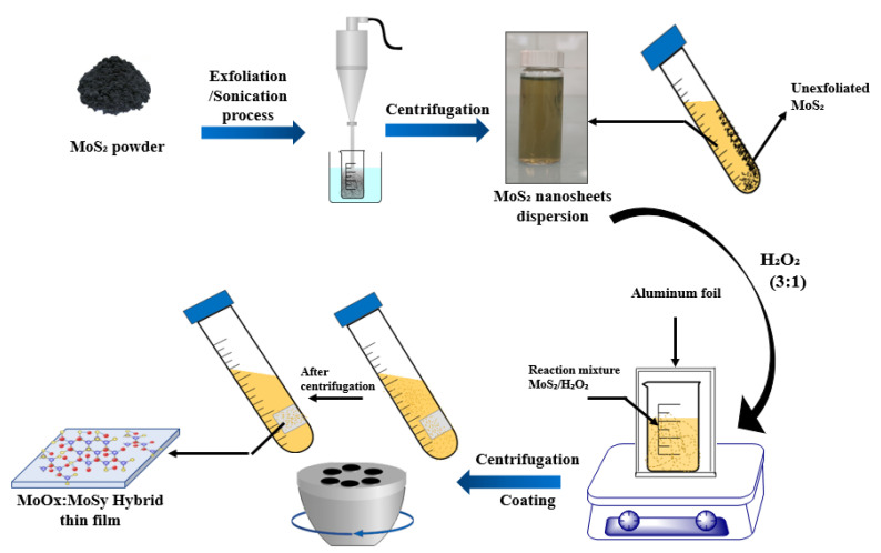
Thin films preparation: Growth of the MoO3:MoS2 and MoS2 thin films was achieved using centrifugal force as a coating technique; this technique is reported in the reference [25], and the exfoliated MoS2 is used as the starting dispersion. The deposition process is described in Figure 1.
Figure 1.
Schematic illustration of MoS2 exfoliation and hybrid thin film preparation by centrifugation-coating.
The hybrid MoO3:MoS2 thin films were obtained according to the oxidation of MoS2, and all the used parameters were kept as described above, except the starting nanodispersion, where the commercial MoS2 nanopowder was replaced by the exfoliated MoS2 dispersion intending to obtain homogenous thin films. The exfoliated MoS2 centrifuged at 600× g was used to keep the same mass concentration, 1 mg mL−1, as it is adopted in the first protocol of the partial nanopowder oxidation. Note that all the reactions have been released in the dark condition during the hybrid thin film preparation.
The obtained MoS2 dispersions after exfoliation/oxidation and the exfoliated MoS2 were transferred to another centrifuge tube with graduation of 50 mL where an ITO-coated PET flexible substrate was introduced and stuck on the edge bottom of the centrifuge tube using an adhesive tape. Due to the centrifugal force applied to the dispersion, thin films were deposited uniformly on the flexible substrates that have a dimension of 2.5 2.5 cm2 or 1 2.5 cm2. All the thin films were deposited at the relative centrifugal force of 8000 for 10 min using a Sigma 2–16 p centrifuge. With no annealing, the obtained thin films, MoO3:MoS2 and MoS2 layers, were stored in the primary vacuum under pressure of 2.10−2 mbar.
The details of the characterization techniques used in this work are given in Appendix A.
3. Results
The hybrid MoO3:MoS2 nanomaterial was synthesized through partial oxidation of MoS2 using H2O2 as an oxidizer. The XPS analyses were performed to check and identify the samples chemical composition after the oxidation process.
The binding energies of the main peaks detected in the XPS spectra and their corresponding components, MoS2, MoO3, and MoOxSy, extracted from the literature are listed in Table 1.
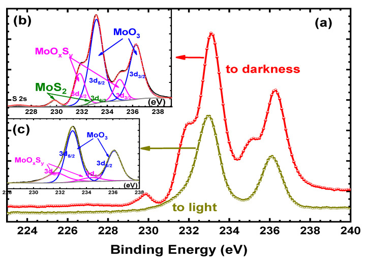
First, MoS2 was oxidized at room conditions by H2O2, whose concentration was 10%, for different durations, 30–15 min. Unfortunately, whatever the reaction duration, as shown in Figure 2a,c, no more MoS2 was detected. Actually, the Mo 3d spectrum corresponds to two doublets; the first one, situated at 232.9 and 236.0 eV can be attributed to the Mo3d5/2 and Mo3d3/2 of MoO3, while the second one, at 231.7 and 234.8 eV corresponds to MoOxSy (see Table 1) [26]. From these results, MoS2 is nearly completely converted to MoO3, suggesting full oxidation of MoS2, and even if these results indicate that MoS2 is oxidized in the appropriate path to MoO3, it does not allow us to achieve one of the main objectives of our work, which is obtaining the hybrid MoO3:MoS2. Therefore, to try to slow down the oxidation reaction, the samples were put to darkness during the reaction. As visible in Figure 2a,b, for a reaction time of 15 min, some MoS2 is still present, indicating that the MoS2 oxidation rate decreases when the reaction is carried out in the dark.
Figure 2.
Mo3d spectra of MoS2 oxidized by H2O2 (10%) for 15 min to light and to darkness (a). Inset (b) Mo3d decomposition after oxidation to darkness and inset. (c) Mo3d decomposition after oxidation to light.
Table 1.
XPS-binding energies of MoS2, MoO3, and MoOxSy.
To be able to control more easily the percentage of MoS2 still present at the end of the reaction, we decided to use a small concentration of H2O2 for the oxidation reaction. Therefore, we proceed to an oxidation using H2O2 concentrations of 6%. To confirm the influence of light on the oxidation reaction, we compared the Mo3d spectra obtained after 30 min with and without light. The results of the deconvolution of the Mo3d spectra are summarized in Table 2. The atomic percentage of MoS2 after 30 min of reaction is nearly double when the reaction is carried out in darkness. Thus, as expected, the MoS2 oxidation rate decreases when the synthesis was performed in the dark conditions. Therefore, it is easier to manage the composition of the hybrid material by working in the dark. Therefore, we decided to proceed with oxidation in darkness.
Table 2.
Composition of the hybrid nanopowder after oxidation of MoS2 by H2O2 6% for 30 min, in function of light environment: to light or in the dark.
| Experimental Conditions | MoS2 (at%) | MoO3 (at%) | MoOxSy (at%) |
|---|---|---|---|
| To light | 17 | 71 | 12 |
| To darkness | 30 | 60 | 10 |
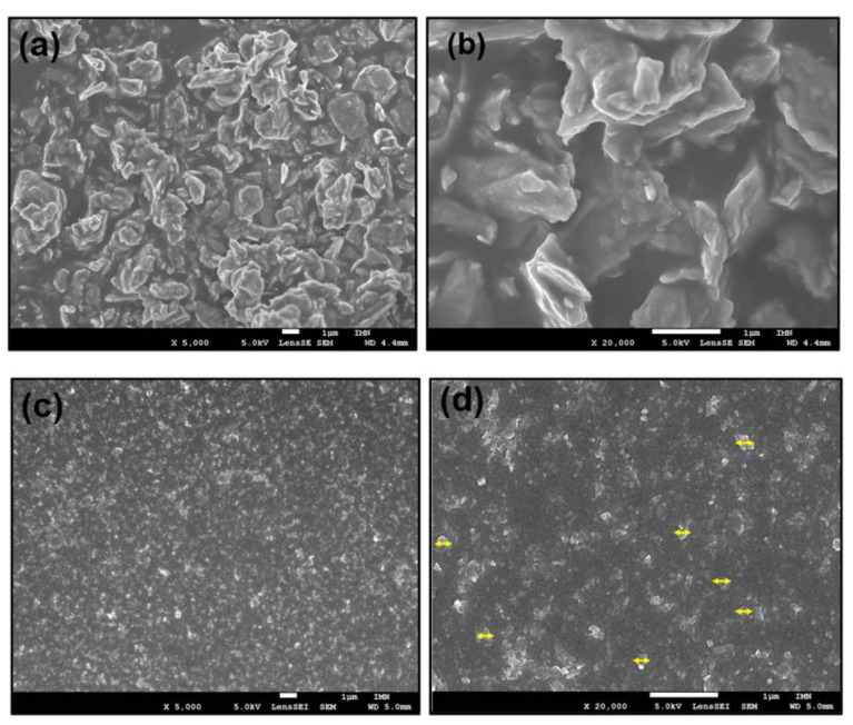
The idea was to sweep the composition of the nanopowder from 100% of MoS2 not oxidized to 0% after oxidation, using the reaction time as parameter. Unfortunately, when the reaction duration increases beyond 30 min, the oxidation reaction tends to saturate; thus, the longer the reaction duration increases, the faster the oxidation rate decreases. Thereby, while for the 30 min reaction time only 30% of MoS2 remains, for 45 min or more, the measured value remains above 20–25%. Indeed, it is an average value because the result changes significantly from one point to another, which suggests that the samples are not homogeneous. If the nominal grain size of MoS2 nanopowder is 90 nm, it is in fact an average value, and some grains are far much larger, reaching a size up to 3 µm, as shown in Figure 3a.
Figure 3.
FESEM images of (a) MoS2 nanopowder and (b) MoS2 nanpowder at high magnification, (c) exfoliated MoS2, (d) exfoliated MoS2 at high magnification, and the yellow arrows indicate the grain lateral sizes.
The presence or not of such big MoS2 grains explains the inhomogeneity of the results and the saturation tendency of the oxidation reaction since it is more difficult to achieve complete reaction in the case of grains of several microns in diameter than in the case of grains of a few tens of nanometers. Since the XPS analysis is essentially a surface analysis, we used the SEM backscattered electron mode [29] to verify the homogeneity of the samples and especially the presence of the MoS2 after the oxidation reaction.
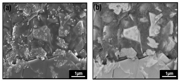
Images of MoS2 nanopowder crystal after oxidation by H2O2 6% for 45 min in the secondary mode and in the backscattering mode are shown in Figure 4a,b. Lighter areas are visible in Figure 4b; they correspond to non-oxidized MoS2 since the heavier atoms backscatter the electrons more than lighter atoms. The dark spots are supposed to correspond to the lightest components, which are the oxidized MoS2; thus, these images clearly show the limits of the XPS analysis, as mentioned above. However, a vital point that can be extracted from these results is MoS2 does not react homogeneously due to the non-homogenous distribution of MoS2 grain size. Starting from the point that H2O2 can be oxidized and spontaneously exfoliate MoS2, as given in previous work [30], it is not beneficial and not easy to directly prepare a homogenous hybrid from MoS2 nanopowder; thus, the synthetic process requires another step to keep the control on the reproducibility of the results regarding the critical dependence between oxidation reaction rate and nanoparticles size.
Figure 4.
FESEM images of MoS2 powder crystal after oxidation of MoS2 by H2O2 6% for 45 min: (a) in the secondary mode and (b) in the backscattering mode.
It can be concluded from this study of that it is possible to convert MoS2 into MoO3 by H2O2 oxidation, but in addition, we showed that to be able to better manage the reaction rate it was desirable to carry out the oxidation in darkness. Nevertheless, the reaction tends to saturate even when the reaction time increases due to the samples non-homogeneity, as shown by SEM analyses. Therefore, for a controllable oxidation rate, it was necessary to work with a MoS2 nanopowder more homogeneous and of real nanometric dimensions. For that reason, we exfoliated MoS2 to obtain smaller particles exhibiting more homogeneous dimensions.
Keeping the same preparation strategy of the hybrid MoO3:MoS2, the liquid phase exfoliation (LPE) was first carried out for MoS2 initial powder. LPE, as one of the top-down approaches, is a way to control the 2D MoS2 flake morphology and proceed our hybrid synthetic strategy based on MoS2 oxidation. Based on recent studies, we believe that the LPE free organic solvent may be a promising technique for specific applications; thus, we proceed in our work for an exfoliation of MoS2 in water [17,31,32]. The details of the exfoliation procedure are described in the experimental section.
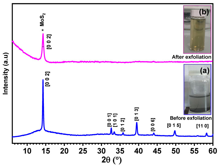
From the photographs showed in Figure 5, the change of the dispersion color from dark gray to yellow color after exfoliation indicate the exfoliation of MoS2. To confirm the exfoliation and identify the crystallinity of exfoliated MoS2 thin film, the X-ray diffraction technique was conducted on commercial MoS2 and exfoliated MoS2 samples. Based on the XRD patterns presented in Figure 5a,b, exfoliated MoS2 shows a peak with high intensity at 2Ɵ ~ 14° corresponding to the (002) plane of MoS2 (PDF.04-004-1905), suggesting that the hexagonal structure of MoS2 is retained after exfoliation [17]. The widening of the peak (002) and disappearance of the rest of the peaks after exfoliation compared to MoS2 nanopowder indicates the efficient exfoliation of MoS2 [33,34].
Figure 5.
X-ray diffraction of MoS2 commercial nanopowder (a) and after exfoliation (b). The inset figures represent dispersions (a) before and (b) after exfoliation.
Before going through the oxidation reaction of the exfoliated MoS2, we checked first the sample morphologies using SEM analysis. From the images shown in Figure 3b, we can clearly observe that the particles size was reduced from several microns for commercial powder to 200–250 nm in lateral size at the maximum and with thin flakes for exfoliated MoS2. Thus, it confirms the exfoliation of the MoS2 nanopowder accompanied the flakes fragmentation during the exfoliation process. As well, we can see the homogenous distribution of the nanoparticles for the sample after exfoliation which is another decisive and important point for our hybrid preparation procedure.
After exfoliation, the nanoparticles are much smaller and more homogeneous than those of the nanopowder; thus, to avoid too rapid oxidation, we used 3% concentration of H2O2 to achieve the reaction. The oxidation reaction of MoS2 and the synthetic route of the hybrid MoO3:MoS2 thin layer is illustrated in the above scheme (Figure 1).
First, we looked at the reproducibility of the results. To do this, we chose a reaction time of 10 min and a concentration of H2O2 of 3%. As shown by the atomic percentage of MoS2 in Table 3, the results obtained with the exfoliated MoS2 are far more reproducible than those obtained with MoS2 nanopowder. Changes in the relative concentrations of MoO3 and MoOxSy are because the energies of the corresponding doublets are close, which induces a certain margin of uncertainty when the corresponding signal is decomposed.
Table 3.
Atomic percentages extracted from Mo 3d XPS spectra of the components present in the MoO3:MoS2 hybrid thin film after 10 min of reaction in the darkness, the H2O2 concentration being 3%.
| Sample | MoS2 (at%) | MoO3 (at%) | MoOxSy (at%) |
|---|---|---|---|
| N°1 | 18 | 62 | 20 |
| N°2 | 17 | 56 | 27 |
| N°3 | 16 | 66 | 17 |
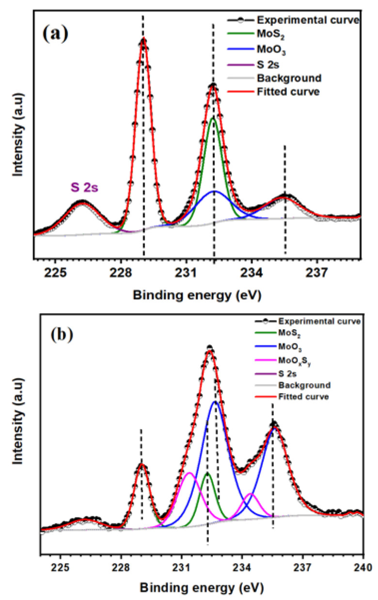
To better understand the reaction process, we looked at the XPS spectra of all components of the hybrid layer. Firstly, Mo 3d spectra of MoO3:MoS2 and MoS2 thin films deposited on the ITO/PET substrate are presented in Figure 6. From the Mo3d spectrum of MoS2 thin film, we can observe two doublets, the first at almost 229 eV and 232 eV corresponding to MoS2 and the second doublet at almost 232 eV and 235 eV which correspond to the Mo5+ oxidation state that can be attributed to the MoOxSy (Table 1); the presence of a low quantity of this intermediate product in MoS2 thin film is coming from MoS2 oxidation during the exfoliation process [35]. After MoS2 oxidation using H2O2, we can observe a doublet peak with high intensity at 232.6 eV and 235.6 eV corresponding to MoO3 [27] and MoS2 at binding energies of 229 eV and 232 eV. The conversion of MoS2 to MoO3 is accompanied by the third compound at energies of 232 eV and 235 eV corresponding to MoOxSy.
Figure 6.
Mo 3d XPS spectra of (a) MoS2 thin layer and (b) MoO3:MoS2 reaction duration of 10 min.
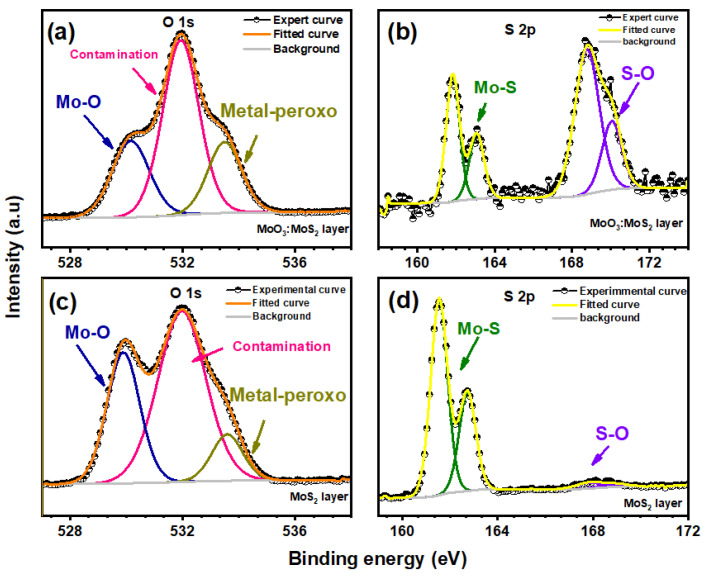
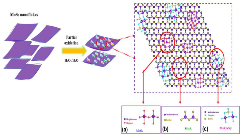
The reaction mechanism of MoS2 oxidation is generally described through the reaction of a free hydroxyl radical coming from H2O2, involved in Mo-S breaking and oxidation of S2− and Mo4+ leading to the formation of MoO3 [10,36]. However, the oxidation of Mo4+ may not be totally achieved since the decomposition of the Mo3d peaks reveals the presence of an intermediate product in the hybrid layer that corresponds to the oxidation state of Mo5+; as reported by S. Shin et al., this intermediate corresponds to MoOxSy named molybdenum oxysulfide, which is related to the incomplete substitution of sulfur by oxygen [37,38]. To discuss the reaction process, S 2p and O1s spectra of the hybrid thin film are illustrated in Figure 7; it can be seen in the S2p spectrum that there is a spin-orbit doublet at the binding energy of 161 eV and 163 eV corresponding to the oxidation state S2− which also confirms the existence of MoS2 moieties in the hybrid thin film [26]. Moreover, we have detected an additional weak peak at binding energy around 169 eV for the MoS2 layer before oxidation [26,38]; the presence of this peak at higher binding energy is mostly attributed to the presence of sulfate (SO42−) due to air contamination and the exfoliation process of MoS2 as reported in the previous works [35,39]. This peak becomes dominant at almost the same binding energy for the hybrid layer with the appearance of the Mo5+ oxidation state which is attributed to the existence of MoOxSy. This finding was also reported by S. Ho Song et al. in their work, where the presence of MoOxSy is accompanied with the appearance of the sulfur peak at higher binding energy of almost 169 eV [26]. Based on the Mo 3d and S 2p spectra, the presence of MoOxSy is related to the association of sulfur and molybdenum with oxygen, which means that the oxygen environment in the hybrid layer is composed of Mo and sulfur. Thus, the presence of Mo-O-S bonds showed after the peak’s deconvolution, giving the new intermediate product the name of oxo-bridge molybdenyl sulfate rather than O-Mo-S bonds. For further details, the deconvolution of O 1 s peaks presented in Figure 7a,c showed the presence of three types of bonding for both oxidized and not oxidized MoS2; the peak situated at almost 530 eV is attributed to metal-oxygen (Mo-O), the peak at an energy >531 eV is mostly due to oxygen-sulfur (O-S), and the middle peak detected at an energy of 531 eV which is indicated by “contamination” is attributed to adsorbed contamination and oxygen-carbon that is present in the PET substrate [37]. The peak area of oxygen-sulfur indicates that the amount of O-S bonds increases after MoS2 oxidation, and the S2p peak at higher binding energy becomes dominant; this confirms the presence of a small amount of free sulfur oxide accompanied with the new composite oxo-bridge molybdenyl sulfate MoOxSy. A hypothetical structure of this new component produced during the process is illustrated in Figure 9c.
Figure 7.
S2p and O 1s zone spectra of MoS2 after reaction duration of 10 min (a,b) and MoS2 before reaction (c,d).
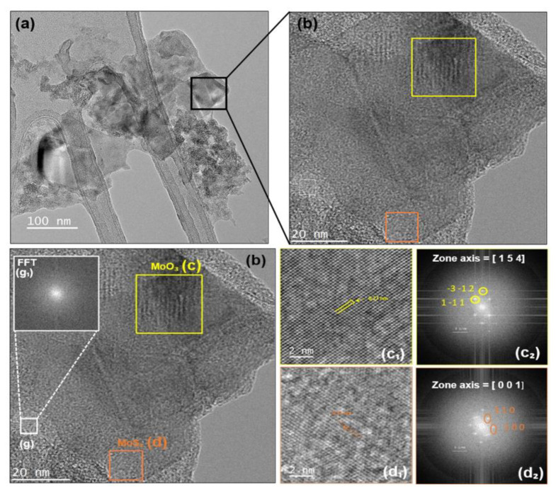
To determine the crystallinity of the MoO3:MoS2 hybrid layer, we did the XRD characterizations; the XRD patterns (not shown) present a weak peak at 14° corresponding to (002) peak of hexagonal structure of MoS2 for both the MoS2 layer and MoO3:MoS2 hybrid layer with the presence of peaks derived from the ITO/PET substrate. Thus, this confirms the crystalline structure of MoS2 present in the hybrid layer. The absence of additional peaks corresponding to MoO3 or the intermediate product, MoOxSy, may be due to the amorphous structure of those compounds or an amount below the detection limit. Furthermore, high-resolution TEM was used to verify the crystalline structure of the studied samples. Figure 8 shows the HRTEM image of the MoO3:MoS2 hybrid obtained after MoS2 oxidation with 30 min of reaction duration; from this image we can observes different zones with a highly crystalline structure as indicated by squares on the image (Figure 8c,d) and other areas with a disordered structure as we can see in Figure 8g. Using fast Fourier transform (FFT) patterns of the selected areas, b2, c2, and g1, we can confirm that the slightly dark color contrast TEM (Figure 8c) is attributed to the crystalline structure of MoO3 with a lattice spacing of 0.27 nm, which corresponds to the plan (1–11). The selected area with the orange square (d) reveals the presence of a hexagonal structure of MoS2 with a lattice parameter of 0.31 nm [40,41]. As evident in the FFT pattern (Figure 8g1), the disordered areas indicate the presence of an amorphous structure which maybe correspond to the oxo-bridge molybdenyl sulfate, MoOxSy, as already revealed by XPS measurements. Briefly, through the oxidation reaction, we obtained nanosheets consisting of a heterostructure containing the three components, MoO3, MoS2, and MoOxSy.
Figure 8.
(a) HRTEM of MoO3:MoS2 hybrid nanosheet; (b) high magnification image of MoO3:MoS2 hybrid nanosheet. The (c) and (d) selected areas with their corresponding high magnification (c1,d1) and FFT (c2,d2) images indexed with JEMS software [42], respectively; (g1) FFT image of the selected area (g).
Based on the above results, the synthetic process of the hybrid MoO3:MoS2 produced during the MoS2 nanoflakes oxidation can be illustrated as follow (Figure 9).
Figure 9.
Illustration of the hybrid MoO3:MoS2 synthetic process, and the chemicals structure of (a) MoO3 (b) MoS2 and (c) MoOxSy.
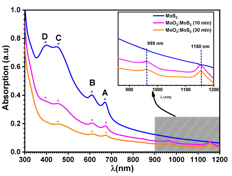
The absorbance spectra of exfoliated MoS2 and the hybrid after reaction durations of 10 min and 30 min are shown in Figure 10. As it is expected, MoS2 exhibited four absorption peaks; these peaks are attributed to the excitonic transitions, A, B, C, and D (see Table 4) [43]. From the absorption spectra the estimated bandgap is 1.77 eV for exfoliated MoS2. It is known that the thickness reduction shifts the band gap from indirect to direct transition; therefore, herein the increase in the bandgap to 1.77 eV indicates the exfoliation of MoS2 to monolayers [17]. Whereas, after the oxidation reaction, the excitonic transitions A and B are almost invariable, which means that the MoS2 unreacted during the reaction remains highly crystalline, which is characterized by good absorption in the visible region. Furthermore, in the NIR the hybrid shows two absorption bands at wavelengths of 959 nm and 1150 nm, corresponding to the energies of 1.29 eV and 1.07 eV (inset Figure 10). However, the absorption peaks become weaker when the reaction duration increases due to the decrease in the density of oxygen vacancies [44].
Figure 10.
Absorbance spectra of exfoliated MoS2 (blue line) and MoO3:MoS2 dispersion as function of reaction durations of 10 min (pink line) 30 min (orange line).
Table 4.
Positions of the excitonic peaks.
| Excitonic Transition | Exfoliated MoS2 | Hybrid MoO3:MoS2 | |
|---|---|---|---|
| 10 min | 30 min | ||
| A | 670 | 673 | 673 |
| B | 607 | 610 | 610 |
| C | 448 | 454 | 454 |
| D | 398 | 398 | ----- |
Considering these results, we have studied the evolution of the composition of the hybrid with the time reaction at fixed H2O2 concentration of 3%. The XPS results are summarized in Table 5.
Table 5.
Evolution with the reaction time of the composition of the hybrid thin film (3% H2O2, in the darkness), based on decomposition of Mo 3d peaks.
| Reaction Duration (min) | MoS2 (at%) | MoO3 (at%) | MoOxSy (at%) |
|---|---|---|---|
| 5 | 25 | 56 | 19 |
| 10 | 17 | 60 | 23 |
| 15 | 5 | 52 | 43 |
| 30 | 4 | 66 | 30 |
| 45 | 2.5 | 75 | 23 |
It can be seen in Table 5 that with the reaction with a H2O2 concentration of 3% it is possible to manage the atomic concentration of MoS2 present in the hybrid layer from 25% after 5 min of reaction to 2.5% after 45 min. It is thus possible to obtain the desired composition for the hybrid layer according to its intended use.
From Figure 6 and Table 5, after 10 min of reaction duration, 60% of MoO3 was produced from the MoS2 oxidation process after 10 min and 66% after 30 min, giving the MoO3/MoS2 ratios of 3.5 and 16, respectively. Hence, the MoO3:MoS2 ratios increase with the time reaction suggesting that there is a relation between the atomic percentage and the reaction duration, where the MoS2 atomic percentage decreases and MoO3 increases by increasing the reaction duration. The new component MoOxSy atomic percentage increases with the reaction duration until its saturation at 15 min with a maximum percentage of 43%, and then the atomic percentage starts to decrease with the reaction duration; this indicates that the MoOxSy content also depends on the reaction and the content of oxygen incorporated. Regarding these results, the control of the reaction duration allows us to obtain a high MoO3 atomic percentage, which is an essential advantage for the use of the hybrid MoO3:MoS2 in optoelectronic application and especially in OPVs as the hole transport layer (HTL). The operation of the HTL hybrid layer depends on the atomic percentage of MoO3 which must be dominant and that is confirmed by our previous work. We note that, the synthesis of the hybrid MoO3:MoS2 layer in our previous work was carried out using sulfidation of MoO3 thin film, and the control of its composition was achieved by varying the annealing temperature of the substrate. The application of this hybrid as the hole transport layer in the planar heterojunction solar cells gives better results when the atomic percentage of MoS2 in the hybrid layer does not exceed 5 %, which corresponds to 65% of the MoO3 atomic percentage; therefore, the presence of a high MoS2 content (>5%), which means low MoO3 concentrations in the hybrid MoO3:MoS2, could limit the positive effect of the hybrid layer when used as HTL. Taking into account these previously obtained results, the presence of such a high MoO3 percentage of about 65% in the MoO3:MoS2 layer as HTL is beneficial for enhancing the photovoltaic performances due to the improvement of the band matching at the electrode and photoactive layer interface [24]. On the basis of this finding, we can conclude that controlling the atomic percentage of such a component of the hybrid layer is necessary to achieve good device performances when the hybrid is introduced; thus, the successful control of the composition achieved in the present work could open up the use of the hybrid prepared by wet chemical synthesis as the hole transport layer (HTL) in the organic solar cells.
Herein, the measurements of the bandgap from the absorption spectra are uncertain; hence, the bandgap is stable at 1.77 eV ± 0.02 for MoS2 and oxidized MoS2. However, the presence of defects under the bandgap due to the presence of the oxo-bridge molybdenyl sulfate, MoOxSy, can improves the holes extractions when it is applied as HTL in solar cells [8]. In a previous report, the MoS2 bandgap can be tuned after its oxidation depending on the MoOxSy atomic percentage where they find that the bandgap extended into the visible range when the MoOxSy contents increased. The MoOxSy reaching 50 at.% induces an increase of the bandgap by 0.25 eV, proving that the modulation of the bandgap is possible by controlling the MoOxSy contents [26]. Thus, this indicates that the presence of the MoOxSy composite can be efficient to reach a wide bandgap energy. In addition, the presence of these defects in the hybrid layer can effectively enhance the absorption ability of MoS2 towards polysulfides, as reported for Li-S batteries [10].
4. Conclusions
In conclusion, we have reported a facile synthetic route to prepare the hybrid MoO3:MoS2 layer via exfoliation/partial oxidation of MoS2 under ambient temperature. Before investigation of the properties of the hybrid layer, the first part was detected in the partial oxidation of MoS2 nanopowder where we found that the reaction can be controlled efficiently in the darkness, and the homogeneity of the grain sizes is needed to obtain high reproducibility of the results. To overcome the non-homogenous results, the second part was dedicated to the exfoliation by LPE to control the grain size homogeneity and therefore, the morphological, optical, and structural properties of the MoS2 and the hybrid MoO3:MoS2 layer.
In the present study, an original method of LPE was done in pure water as the solvent; the use of water is beneficial as it is not only cost-effective in industrial and commercial applications but also facilitates the hybrid synthesis via the MoS2 oxidation. A possible growth mechanism of MoS2, the MoO3:MoS2 thin layer was achieved using centrifugation/coating method.
The Investigation of XPS analyses revealed the presence of the three compounds, MoO3, MoS2, and MoOxSy; this heterostructure was also confirmed by HRTEM analyses. Based on the evolution of the reaction, we found that the atomic percentage of each component depends on the reaction duration; the MoO3 atomic percentage can exceed 60%, and the presence of the oxo-bridge molybdenyl sulfate, MoOxSy, in the hybrid layer justifies the possibility to use this hybrid for large potential applications, especially solar cells, Li-batteries, and catalysis.
Acknowledgments
We gratefully acknowledge « le Partenariat Hubert Curien (PHC) franco-marocain Toubkal project, under contract No. 41406ZC » and « le Centre National de la Recherche Scientifique et Technique CNRST » for supporting this work. We would also to thank Françoise Lari for her technical assistance during the chemical synthesis. Funding by the French Contrat Plan État-Région and the European Regional Development Fund of Pays de la Loire, the CIMEN Electron Microscopy Center in Nantes, is greatly acknowledged.
Appendix A
Chemical compositions of the synthesized hybrid MoO3:MoS2 nanopowder and thin films were investigated by X-ray photoelectron spectroscopy (XPS) analysis at room temperature using the Axis Nova spectrometer (Kratos Analytical) and employing Al Kα line as the excitation source. The spectra were adjusted according to the fixed binding energy of carbon C 1 s at 284.8 eV as a reference. The XPS data were treated using CasaXPS software, the fitting was obtained by a mixed Gaussian–Lorentzian product with 30% and 70% as the contribution of Lorentzian and Gaussian, respectively, for Mo 3d fitting the area ratio of 2:3 was fixed for Mo 3d 5/2 and Mo 3d 3/2, respectively, after the extraction of the Shirley background. The core-level spectra were recorded using a constant pass energy of 20 eV with an energy step of 0.1 eV.
The morphology of the studied hybrid nanomaterials was analyzed using a scanning electron microscopy (SEM) with a JEOL JSM 7600F field-emission scanning electron gun microscope (Centre de micro-caractérisation, Institut des Matériaux de Nantes Jean Rouxel IMN, Nantes université). Images were recorded using a secondary electron detector and a backscattered electron detector, and the accelerating voltage was set to 5 KV. Transmission electron microscopy (TEM) and high-resolution TEM (HRTEM) images were collected by a S/TEM Themis Z G3 (thermo Fisher Scientific) microscope with an operating voltage at 300 KV. The samples analyzed by TEM were prepared by the deposition of a droplet on Cu lacey carbon grid.
Optical absorption spectra were measured at room temperature using a UV-visible-NIR spectrophotometer (Perkin Elmer Lambda 1050 setup) at a normal incidence in the spectral range 300 nm–1200 nm.
X-ray diffraction was done with Diffractometer Burker D8 A25 “Da Vinci” setup using Cu Kα radiation (λKα = 1.5418 Å); the diffractometer is equipped with a second-generation Si strip detector (“LynxEye XE”).
Author Contributions
Conceptualization, H.L., J.C.B., and L.C.; methodology, H.L.; software, G.L., N.G., and N.S.; validation, G.L., Y.M., and J.C.B.; review, M.R.-P., N.G., N.S., and M.Z.; investigation, H.L., J.C.B., G.L., L.C., and H.F.; resources, L.C. and M.A.; data curation, G.L.; writing—original draft preparation, H.L.; writing—review and editing, H.L., G.L.; L.C., and J.C.B.; visualization, Y.M., G.L., and M.Z., supervision, G.L. and Y.M.; project administration, L.C. and M.A.; funding acquisition, L.C. All authors have read and agreed to the published version of the manuscript.
Data Availability Statement
Not available.
Conflicts of Interest
The authors declare no conflict interest.
Funding Statement
Funding by the Hubert Curien (PHC), under French-morocccan grant agreements (TOUBKAL) No.41406ZC.
Footnotes
Publisher’s Note: MDPI stays neutral with regard to jurisdictional claims in published maps and institutional affiliations.
References
- 1.Nakano K., Tajima K. Organic Planar Heterojunctions: From Models for Interfaces in Bulk Heterojunctions to High-Performance Solar Cells. Adv. Mater. 2017;29:1603269. doi: 10.1002/adma.201603269. [DOI] [PubMed] [Google Scholar]
- 2.Gupta A., Arunachalam V., Vasudevan S. Liquid-Phase Exfoliation of MoS 2 Nanosheets: The Critical Role of Trace Water. J. Phys. Chem. Lett. 2016;7:4884–4890. doi: 10.1021/acs.jpclett.6b02405. [DOI] [PubMed] [Google Scholar]
- 3.Singh E., Kim K.S., Yeom G.Y., Nalwa H.S. Atomically Thin-Layered Molybdenum Disulfide (MoS2) for Bulk-Heterojunction Solar Cells. ACS Appl. Mater. Interfaces. 2017;9:3223–3245. doi: 10.1021/acsami.6b13582. [DOI] [PubMed] [Google Scholar]
- 4.Loiacono A., Gomez M.J., Negreiros F.R., Olmos-Asar J.A., Mariscal M.M., Lacconi G.I., Franceschini E.A. MoS2 Effect on Nickel Electrochemical Activation: An Atomistic/Experimental Approach. J. Phys. Chem. C. 2021;125:18640–18652. doi: 10.1021/acs.jpcc.1c03067. [DOI] [Google Scholar]
- 5.Pesci F.M., Sokolikova M.S., Grotta C., Sherrell P.C., Reale F., Sharda K., Ni N., Palczynski P., Mattevi C. MoS2/WS2 Heterojunction for Photoelectrochemical Water Oxidation. ACS Catal. 2017;7:4990–4998. doi: 10.1021/acscatal.7b01517. [DOI] [Google Scholar]
- 6.Duraisamy S., Ganguly A., Sharma P.K., Benson J., Davis J., Papakonstantinou P. One-Step Hydrothermal Synthesis of Phase-Engineered MoS2/MoO3 Electrocatalysts for Hydrogen Evolution Reaction. ACS Appl. Nano Mater. 2021;4:2642–2656. doi: 10.1021/acsanm.0c03274. [DOI] [Google Scholar]
- 7.Yin Z., Zhang X., Cai Y., Chen J., Wong J.I., Tay Y.-Y., Chai J., Wu J., Zeng Z., Zheng B., et al. Preparation of MoS2-MoO3 Hybrid Nanomaterials for Light-Emitting Diodes. Angew. Chem. Int. Ed. 2014;53:12560–12565. doi: 10.1002/anie.201402935. [DOI] [PubMed] [Google Scholar]
- 8.Martinez-Rojas F., Hssein M., El Jouad Z., Armijo F., Cattin L., Louarn G., Stephant N., del Valle M.A., Addou M., Soto J.P., et al. Mo(SxOy) thin films deposited by electrochemistry for application in organic photovoltaic cells. Mater. Chem. Phys. 2017;201:331–338. doi: 10.1016/j.matchemphys.2017.08.021. [DOI] [Google Scholar]
- 9.Seynstahl A., Krauß S., Bitzek E., Meyer B., Merle B., Tremmel S. Microstructure, Mechanical Properties and Tribological Behavior of Magnetron-Sputtered MoS2 Solid Lubricant Coatings Deposited under Industrial Conditions. Coatings. 2021;11:455. doi: 10.3390/coatings11040455. [DOI] [Google Scholar]
- 10.Lei D., Shang W., Zhang X., Li Y., Qiao S., Zhong Y., Deng X., Shi X., Zhang Q., Hao C., et al. Facile Synthesis of Heterostructured MoS2–MoO3 Nanosheets with Active Electrocatalytic Sites for High-Performance Lithium–Sulfur Batteries. ACS Nano. 2021;15:20478–20488. doi: 10.1021/acsnano.1c09007. [DOI] [PubMed] [Google Scholar]
- 11.Zhang Y., Kuwahara Y., Mori K., Qian X., Zhao Y., Yamashita H. Hybrid Phase MoS2 as a Noble Metal-Free Photocatalyst for Conversion of Nitroaromatics to Aminoaromatics. J. Phys. Chem. C. 2021;125:20887–20895. doi: 10.1021/acs.jpcc.1c06236. [DOI] [Google Scholar]
- 12.Kim J., Jung M., Lim D.U., Rhee D., Jung S.H., Cho H.K., Kim H.-K., Cho J.H., Kang J. Area-Selective Chemical Doping on Solution-Processed MoS2 Thin-Film for Multi-Valued Logic Gates. Nano Lett. 2022;22:570–577. doi: 10.1021/acs.nanolett.1c02947. [DOI] [PubMed] [Google Scholar]
- 13.Liu C., Wang C., Liao C., Golder J., Tsai M., Young H., Chen C., Wu C.-I. Solution Processable Mixed-Solvent Exfoliated MoS 2 Nanosheets for Efficient and Robust Organic Light-Emitting Diodes. AIP Adv. 2018;8:045006. doi: 10.1063/1.5020708. [DOI] [Google Scholar]
- 14.Park M., Nguyen T.P., Choi K.S., Park J., Ozturk A., Kim S.Y. MoS2-Nanosheet/Graphene-Oxide Composite Hole Injection Layer in Organic Light-Emitting Diodes. Electron. Mater. Lett. 2017;13:344–350. doi: 10.1007/s13391-017-1612-3. [DOI] [Google Scholar]
- 15.Dasgupta U., Chatterjee S., Pal A.J. Thin-Film Formation of 2D MoS2 and Its Application as a Hole-Transport Layer in Planar Perovskite Solar Cells. Sol. Energy Mater. Sol. Cells. 2017;172:353–360. doi: 10.1016/j.solmat.2017.08.012. [DOI] [Google Scholar]
- 16.Lin Y., Adilbekova B., Firdaus Y., Yengel E., Faber H., Sajjad M., Zheng X., Yarali E., Seitkhan A., Bakr O.M., et al. 17% Efficient Organic Solar Cells Based on Liquid Exfoliated WS2 as a Replacement for PEDOT:PSS. Adv. Mater. 2019;31:1902965. doi: 10.1002/adma.201902965. [DOI] [PubMed] [Google Scholar]
- 17.Ma H., Shen Z., Ben S. Understanding the exfoliation and dispersion of MoS2 nanosheets in pure water. J. Colloid Interface Sci. 2018;517:204–212. doi: 10.1016/j.jcis.2017.11.013. [DOI] [PubMed] [Google Scholar]
- 18.Rakibuddin M., Shinde M.A., Kim H. Facile sol–gel fabrication of MoS2 bulk, flake and quantum dot for electrochromic device and their enhanced performance with WO3. Electrochim. Acta. 2020;349:136403. doi: 10.1016/j.electacta.2020.136403. [DOI] [Google Scholar]
- 19.Li X., Zhang W., Wu Y., Min C., Fang J. Solution-Processed MoSx as an Efficient Anode Buffer Layer in Organic Solar Cells. ACS Appl. Mater. Interfaces. 2013;5:8823–8827. doi: 10.1021/am402105d. [DOI] [PubMed] [Google Scholar]
- 20.Tsigkourakos M., Kainourgiaki M., Skotadis E., Giannakopoulos K.P., Tsoukalas D., Raptis Y.S. Capping technique for chemical vapor deposition of large and uniform MoS2 flakes. Thin Solid Film. 2021;733:138808. doi: 10.1016/j.tsf.2021.138808. [DOI] [Google Scholar]
- 21.Hu L., Ren Y., Yang H., Xu Q. Fabrication of 3D Hierarchical MoS2/Polyaniline and MoS2/C Architectures for Lithium-Ion Battery Applications. ACS Appl. Mater. Interfaces. 2014;6:14644–14652. doi: 10.1021/am503995s. [DOI] [PubMed] [Google Scholar]
- 22.Ramasamy M.S., Ryu K.Y., Lim J.W., Bibi A., Kwon H., Lee J., Kim D.H., Kim K. Solution-Processed PEDOT:PSS/MoS2 Nanocomposites as Efficient Hole-Transporting Layers for Organic Solar Cells. Nanomaterials. 2019;9:1328. doi: 10.3390/nano9091328. [DOI] [PMC free article] [PubMed] [Google Scholar]
- 23.Yun J., Noh Y., Lee C.-H., Na S., Lee S., Jo S.M., Joh H., Kim D. Exfoliated and Partially Oxidized MoS2 Nanosheets by One-Pot Reaction for Efficient and Stable Organic Solar Cells. Small. 2014;10:2319–2324. doi: 10.1002/smll.201303648. [DOI] [PubMed] [Google Scholar]
- 24.Ftouhi H., Lamkaouane H., Louarn G., Diani M., Bernède J.C., Addou M., Cattin L. Low temperature synthesis of MoS2 and MoO3: MoS2 hybrid thin films via the use of an original hybrid sulfidation technique. Surf. Interfaces. 2022;32:102120. doi: 10.1016/j.surfin.2022.102120. [DOI] [Google Scholar]
- 25.Kim Y., Yassitepe E., Voznyy O., Comin R., Walters G., Gong X., Kanjanaboos P., Nogueira A.F., Sargent E.H. Efficient Luminescence from Perovskite Quantum Dot Solids. ACS Appl. Mater. Interfaces. 2015;7:25007–25013. doi: 10.1021/acsami.5b09084. [DOI] [PubMed] [Google Scholar]
- 26.Song S.H., Kim B.H., Choe D.-H., Kim J., Kim D.C., Lee D.J., Kim J.M., Chang K.J., Jeon S. Bandgap Widening of Phase Quilted, 2D MoS2 by Oxidative Intercalation. Adv. Mater. 2015;27:3152–3158. doi: 10.1002/adma.201500649. [DOI] [PubMed] [Google Scholar]
- 27.Bortoti A.A., de Freitas Gavanski A., Velazquez Y.R.., Galli A., de Castro E.G. Facile and low cost oxidative conversion of MoS2 in α-MoO3: Synthesis, characterization and application. J. Solid State Chem. 2017;252:111–118. doi: 10.1016/j.jssc.2017.05.006. [DOI] [Google Scholar]
- 28.Hwang M.-J., Han S.W., Nguyen T.-B., Hong S.C., Ryu K.-S. Preparation of MoO3/MoS2/TiO2 Composites for Catalytic Degradation of Methylene Blue. J. Nanosci. Nanotechnol. 2012;12:5884–5891. doi: 10.1166/jnn.2012.6302. [DOI] [PubMed] [Google Scholar]
- 29.Kejzlar P., Švec M., Macajová E. The Usage of Backscattered Electrons in Scanning Electron Microscopy. Manuf. Technol. 2014;14:333–336. doi: 10.21062/ujep/x.2014/a/1213-2489/MT/14/3/333. [DOI] [Google Scholar]
- 30.Dong L., Lin S., Yang L., Zhang J., Yang C., Yang D., Lu H. Spontaneous exfoliation and tailoring of MoS2 in mixed solvents. Chem. Commun. 2014;50:15936–15939. doi: 10.1039/C4CC07238C. [DOI] [PubMed] [Google Scholar]
- 31.Kim J., Kwon S., Cho D.-H., Kang B., Kwon H., Kim Y., Park S.O., Jung G.Y., Shin E., Kim W.-G., et al. Direct Exfoliation and Dispersion of Two-Dimensional Materials in Pure Water via Temperature Control. Nat. Commun. 2015;6:8294. doi: 10.1038/ncomms9294. [DOI] [PMC free article] [PubMed] [Google Scholar]
- 32.Rodriguez C.L.C., Muñoz P.A.R., Donato K.Z., Seixas L., Donato R.K., Fechine G.J.M. Understanding the Unorthodox Stabilization of Liquid Phase Exfoliated Molybdenum Disulfide (MoS2) in Water Medium. Phys. Chem. Chem. Phys. 2020;22:1457–1465. doi: 10.1039/C9CP06422B. [DOI] [PubMed] [Google Scholar]
- 33.Walia S., Balendhran S., Wang Y., Ab Kadir R., Sabirin Zoolfakar A., Atkin P., Zhen Ou J., Sriram S., Kalantar-zadeh K., Bhaskaran M. Characterization of metal contacts for two-dimensional MoS2 nanoflakes. Appl. Phys. Lett. 2013;103:232105. doi: 10.1063/1.4840317. [DOI] [Google Scholar]
- 34.Yang X., Fu W., Liu W., Hong J., Cai Y., Jin C., Xu M., Wang H., Yang D., Chen H. Engineering crystalline structures of two-dimensional MoS2 sheets for high-performance organic solar cells. J. Mater. Chem. A. 2014;2:7727–7733. doi: 10.1039/C4TA01336K. [DOI] [Google Scholar]
- 35.Wang J., Huang C., You Y., Guo Q., Xue G., Hong H., Jiao Q., Yu D., Du L., Zhao Y., et al. Monitoring the Material Quality of Two-Dimensional Transition Metal Dichalcogenides. J. Phys. Chem. C. 2022;126:3797–3810. doi: 10.1021/acs.jpcc.2c00051. [DOI] [Google Scholar]
- 36.Mandal D., Routh P., Nandi A.K. Quantum-Dot-Mediated Controlled Synthesis of Dual Oxides of Molybdenum from MoS2: Quantification of Supercapacitor Efficacy. Chem. Asian J. 2018;13:3871–3884. doi: 10.1002/asia.201801173. [DOI] [PubMed] [Google Scholar]
- 37.Iqbal N., Khan I., Ali A., Qurashi A. A sustainable molybdenum oxysulphide-cobalt phosphate photocatalyst for effectual solar-driven water splitting. J. Adv. Res. 2022;36:15–26. doi: 10.1016/j.jare.2021.08.006. [DOI] [PMC free article] [PubMed] [Google Scholar]
- 38.Shin S., Jin Z., Ham S.-Y., Lee S., Shin D.-S., Min Y.-S. Effect of oxygen incorporation in amorphous molybdenum sulfide on electrochemical hydrogen evolution. Appl. Surf. Sci. 2019;487:981–989. doi: 10.1016/j.apsusc.2019.05.188. [DOI] [Google Scholar]
- 39.Afanasiev P., Lorentz C. Oxidation of Nanodispersed MoS2 in Ambient Air: The Products and the Mechanistic Steps. J. Phys. Chem. C. 2019;123:7486–7494. doi: 10.1021/acs.jpcc.9b01682. [DOI] [Google Scholar]
- 40.Muscuso L., Cravanzola S., Cesano F., Scarano D., Zecchina A. Optical, Vibrational, and Structural Properties of MoS2 Nanoparticles Obtained by Exfoliation and Fragmentation via Ultrasound Cavitation in Isopropyl Alcohol. J. Phys. Chem. C. 2015;119:3791–3801. doi: 10.1021/jp511973k. [DOI] [Google Scholar]
- 41.Shi Y., Li H., Wong J.I., Zhang X., Wang Y., Song H., Yang H.Y. MoS2 Surface Structure Tailoring via Carbonaceous Promoter. Sci. Rep. 2015;5:10378. doi: 10.1038/srep10378. [DOI] [PMC free article] [PubMed] [Google Scholar]
- 42.Stadelmann P. JEMS Electron Microscopy Simulation Software (Version V4) [Software] 2019. [(accessed on 7 September 2022)]. Available online: www.jems-swiss.ch.
- 43.Coleman J.N., Lotya M., O’Neill A., Bergin S.D., King P.J., Khan U., Young K., Gaucher A., De S., Smith R.J., et al. Two-Dimensional Nanosheets Produced by Liquid Exfoliation of Layered Materials. Science. 2011;331:568–571. doi: 10.1126/science.1194975. [DOI] [PubMed] [Google Scholar]
- 44.Fernandes Cauduro A.L., Fabrim Z.E., Ahmadpour M., Fichtner P.F.P., Hassing S., Rubahn H.-G., Madsen M. Tuning the optoelectronic properties of amorphous MoOx films by reactive sputtering. Appl. Phys. Lett. 2015;106:202101. doi: 10.1063/1.4921367. [DOI] [Google Scholar]
Associated Data
This section collects any data citations, data availability statements, or supplementary materials included in this article.
Data Availability Statement
Not available.


