

Abstract
We present the operation result of a cryogen-free 23.5 T/φ12.5 mm-cold-bore magnet prototype composed of a stack of 12 no-insulation (NI) REBCO single pancake coils—ten middle coils of 6-mm wide and two end coils of 8-mm wide tape—forming 6 double pancake (DP) coils with inner joints. Each coil was wound with the tape having only 1-μm-thick copper layer on each side to overcome the conductor thickness uniformity issue and enhance the mechanical strength within the winding, and then, additional electrical shunting by thin layers of solder was applied on the top and bottom surfaces of each DP coil for effective cooling and quench protection—called extreme-NI winding technique. With this small prototype magnet towards a benchtop 1-GHz NMR, we validate our coil design that include conductor performance, screening-current-induced field and stresses, and conduction-cooling cryogenics. Included in the paper are: 1) conductor issues and our counterproposal in winding; 2) screening-current reduction method; 3) design and manufacture summary of the magnet; and 4) operating test results of the magnet up to 25 Tesla.
Index Terms—: Extreme-No-Insulation, High-Field Magnets, No-Insulation, Nuclear Magnetic Resonance, REBCO Magnets
I. Introduction
Convinced that a benchtop 1-GHz nuclear magnetic resonance (NMR) magnet would greatly impact NMR community, we have been developing a small-scale 23.5-T prototype magnet [1]. Viable features of our benchtop NMR magnet include compactness (25 mm room-temperature bore), high B0 field (23.5 T), and liquid-helium-free cryogenics. We accordingly have proposed a conduction-cooled, all-HTS magnet adopting the no-insulation (NI) winding technique. By eliminating any cryogen, we believe that the magnet offers ease of handling, simple and safe operation, and cost reduction [2]–[4]. The NI winding technique makes an HTS magnet compact by operating at high overall current density, mechanically robust, and self-protecting [5]–[7]. We have designed and built a cryogen-free REBCO 23.5-T/12.5-mm-cold-bore prototype magnet to validate a conductor performance, coil design parameters, such as critical current, Ic, field and stresses that incorporate screening-current effects, charging characteristics of the NI coil, and conduction-cooling cryogenics which would be used in our proposed benchtop NMR magnet. In this paper, we present a successful operation result of the REBCO magnet up to 25 T without relying on any cryogen with adopting the innovative variation of NI winding, called extreme-NI winding, and applying the screening-current reduction method. We first introduce a motivation to conceive this extreme-NI winding technique, followed by preliminary test results of a test double pancake (DP) coil that we wound with this technique. Then, we present preliminary experimental and analytical results of our screening-current reduction method by adjusting coil temperature. Lastly, we present a brief summary of design, manufacture, and operation results of the cryogen-free REBCO prototype magnet.
II. Extreme-No-Insulation Winding Technique
A. Motivation – Conductor Issues and Counterproposal
For our first test winding with a 6-mm-wide, 65-μm-thick REBCO tape having 5-μm copper electroplating at each side, manufactured by Shanghai Superconductor Technology Co., Ltd. (SSTC) in 2019, with a 50-N winding tension, one of our design parameter of a 23.5-T prototype magnet to keep radial stress compressive [1], we observed an uneven side surface with sharply bumped edge as shown in Fig. 1a. After 90 turns, we measured the outside diameters of top and middle of the test coil that showed a difference of 0.35 mm. It causes very serious damage to the conductor by overstraining its edge with increasing the number of turns: we observed plastically deformed wavy edges as we un-wound the coil. Even if this deformation may be less evident in coil winding with a fewer turns or with a lower winding tension, this over-straining can degrade the coil performance during energization. We examined this test coil by taking a scanning electron microscope (SEM) images of its cross-section. Figure 1b shows two cross-section views of the test coil, the middle and side edge. Note that the copper thickness between two Hastelloy substrates should be ~10 μm (~5-μm copper from each adjacent tape). The copper at the edge was ~4-μm thicker than the one at the middle of the tape. We concluded that the winding deformity was caused by non-uniform thickness of the electroplated copper along the width. We came up with a new idea of thinning copper matrix in NI winding to circumvent thickness variation or uncertainty arising during electroplating process, rather than waiting for the process to be improved, taking more time and being costlier.
Fig. 1.
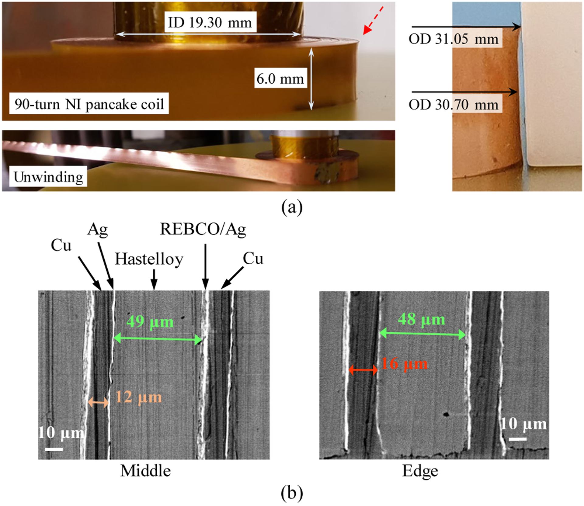
An NI pancake test coil wound with 5+5-μm-thick copper-plated REBCO tape: (a) 90-turn winding and unwinding; (b) SEM images of cross-sections of middle and edge sides of the test coil.
B. Concept and Preliminary Feasibility Testing
We have introduced a novel extremely-thin-copper-stabilized and extra-shunted no-insulation winding concept (extreme-NI winding), which maximizes the NI winding technique advantages of higher operating current density, greater winding mechanical strength by reduced copper [8], and self-protecting feature. Figure 2a shows a concept drawing: first, NI pancake winding with a REBCO tape of thin (≤1 μm) copper matrix; and then electrically shunting turn-to-turn (radial) currents by an additional conductive layer on the winding surface—soldered, electroplated or pressed with an indium sheet.
Fig. 2.

Extreme-NI coil: (a) conceptual drawing; and photos of (b) the bare NI DP coil and (c) the NI DP coil with soldered surfaces.
We have performed preliminary studies to determine the feasibility of this extreme-NI winding technique by using a 6-mm-wide REBCO tape with 1-μm-thick copper on each side provided by SSTC. A 510-turn test NI DP coil was fabricated to validate the extreme-NI winding concept and the winding procedure as shown in Fig. 2b. The winding diameter of 22.3 mm is the same with the 23.5-T prototype magnet. With this thin-copper REBCO tape, we did not encounter any winding issues. We first tested the NI DP coil, and then, added extra shunts of 52In48Sn solder on top and bottom winding surfaces of this NI DP coil as shown in Fig. 2c. No elaborate methods were used for an extra shunting process, but applied a manual soldering just to see the feasibility of the proposed concept. Over-current tests up to power supply current, Ips of 125 A (~2.8 × Ic) were performed at 77 K for both bare and soldered NI DP coils as shown in Fig. 3a and 3b. As for the bare NI DP coil, when Ips exceeded coil Ic (at t=450 s at 0.1 A·s−1), the superconducting-to-normal transition occurred and, being an NI coil, the excessive current above Ic was directed through a turn-to-turn bypass. The center field was no longer proportional to Ips. At the same time, the joule heating by this excessive current increased winding temperature and thus reduced its Ic. Starting at t=1070 s, the normal zone started propagating and the center field gradually dropped as more turns lost the azimuthal-direction superconducting current. The coil voltage increased more quickly from this point. We can see the decreasing center field and the increasing coil voltage even while Ips was held at 125 A. On the other hand, the soldered NI coil data measured during regular ramping (0.1 A·s−1) and even fast ramping (1 A·s−1) show that the coil is stable and thermally balanced during the entire over-current regime with its field and voltages constant while Ips was held at 125 A. Its center field below Ic is almost identical with the one of the bare NI coils except showing further charging delay, but the maximum center field is lower because more current is bypassing through the extra solder layer. The soldered NI coil voltage and its overall power consumption of the soldered NI coil at Ips=125 A are ~0.04 V and ~5 W, respectively, each a quarter of that of the bare NI coil. Although the over-current in this test coil is less than Iop of our 23.5-T prototype magnet, the self-protecting feature of the extreme-NI coil seems promising.
Fig. 3.
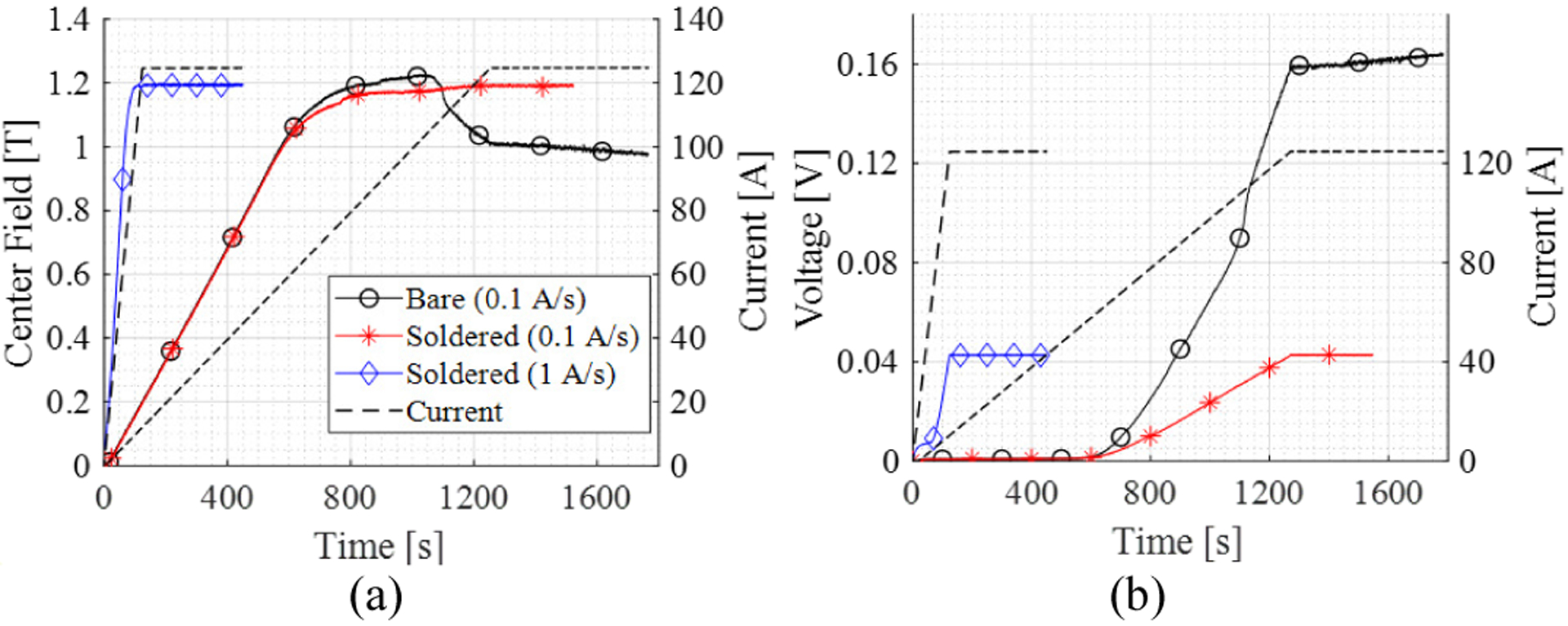
Over-current testing results of test coils, bare and soldered, up to 125 A with 0.1 A·s−1 and 1 A·s−1: (a) center field vs. time; and (b) voltage vs. time.
Turn-to-turn resistance, RT, is a dominant parameter for characterizing NI coils, and any excessive azimuthal current over Ic bypasses through the turn-to-turn radial path along the entire turn [9]–[11]. Note that because the buffer layer is an insulator, we may assume all radial current passes through the edge side copper matrix in REBCO tape. In conventional NI winding, a contact resistance may dominate RT [12], however, if we reduce the copper thickness significantly, the copper resistance at the edge may affect RT more. In the case of using 1-μm-thick copper, the thermal/electrical weakest point could be the thin side edge. By shunting the winding surface with an electrically conductive layer, we can sufficiently reduce RT, and by adding a cooling disk between DP coils, we can also expect to take away the joule heating from the winding. We adopted the extreme-NI winding technique to the cryogen-free 23.5-T REBCO prototype magnet.
III. Screening-Current Reduction Method Validation
In this prototype magnet wound with 6-mm and 8-mm wide REBCO tapes, screening currents are induced during charging or discharging the magnet. The screening currents not only reduce the center field and generate field errors, but also, more seriously, increase the peak stress in the coil. The screening-current-induced field (SCF) can be compensated by shimming or including it in the coil optimization, but the screening-current-induced stress (SCS) which exceeds permissible stress level must be reduced to prevent from permanent damage.
We first performed screening current analysis for the 23.5-T REBCO prototype magnet by using T-A formulation with a 2-dimensional continuous approximation for the coil winding of hundreds turns [13], and then, performed solid mechanical analysis of every single pancake coil of a top half of the prototype magnet with considering winding tension of 120 MPa, thermal contraction, and energization and SCS by using a finite element method [14]. Figure 4a shows a hoop stress distribution in the case of the magnet charged to 23.5 T at 10 K. There are high-stress (>800 MPa) regions in top 4 single pancake coils (and bottom 4 coils as well due to its symmetry) at risk of mechanical failure, that needs to be suppressed. Note that the peak stress computed without considering SCS is only 140 MPa. To keep radial stresses compressive at the outermost turns of the coils, we decided to apply over-banding.
Fig. 4.

Screening currents in the REBCO magnet: (a) hoop stress distribution in the 23.5-T prototype magnet at 10 K; and (b) validation test result by using a single pancake coil ramping up to 255 A.
Then, we built a 660-turn single-pancake NI coil, same size with the one of the 23.5-T prototype magnet, to exclusively test the screening current effect due to changes in coil temperature, and we proved analytically and experimentally that the screening current is reduced when charging the coil to 255 A at higher coil temperature as shown in Fig. 4b. The center field is an indicator of screening currents (that is, more screening currents make the center field lower). The screening current can be reduced as the critical current margin gets reduced [15], [16]. The center field of 4.078 T when charged at 40 K was about 0.06 T (~1.5% of the center field) higher than the field at 10 K ramping; less screening currents were induced. Note that the computed center field at 255 A without screening current is 4.1 Tesla. We successfully demonstrated the screening current reduction method by adjusting coil temperature for charging period. We applied this screening current reduction method to our 23.5-T REBCO prototype magnet.
IV. Results of the Prototype Magnet
A. Design and Manufacture
The prototype magnet is a stack of 6 extreme-NI DP coils composed of ten middle single pancake coils wound with 6-mm-wide 55-μm-thick REBCO tapes and two end single pancake coils with 8-mm-wide one. Each DP coil has an inner joint, rather than continuous winding because 1) a combined bending and torsion strain of 6-mm-wide tape on a cross-over turn at the 22.23-mm ID would be too excessive, and 2) the two end DP coils consisting of 6-mm and 8-mm tapes. A low-temperature eutectic solder, 52In48Sn (melting temperature: 118°C) was used for inner joints and outer joints connecting DP coils. Additional 25-μm-thick copper tapes were soldered on the jointing side of 1-μm copper REBCO tapes to cover the boundary between the jointed tape and the bridge tape to prevent delamination of this very thin copper-coated REBCO tape. With this reliable joint method, we wound 6 DP coils. To complete the extreme-NI winding, we added extra shunts by soldering 52In-48Sn solder on top and bottom surfaces of the DP coils. Then, we built the prototype magnet as follows: stacking the completed DP coils with copper cooling disks and heaters; applying a 10 kN preload; jointing between DP coils; and over-banding by using stainless steel tapes. Table I lists the key parameters of the manufactured prototype magnet. Due to a conductor thickness tolerance from Hastelloy substrate (≤3 μm), the number of turns and winding OD are different from each other coil. We matched the ODs for the adjacent pancake coils for jointing. Figure 5 shows (a) a schematic drawing and (b) a photo of the assembled magnet. All the copper disks placed between DP coils were thermally connected to the cryocooler 2nd stage via copper block. The magnet was conduction-cooled via copper cooling disks and stacked copper blocks, and the magnet temperature reached 4 K after 14 hours of initial cooling. Then, the magnet coil temperature was controlled by adjusting heater currents. Two temperature sensors were mounted on the magnet top and bottom. Temperature deviation within the magnet was less than 1 K. A calibrated cryogenic hall sensor was mounted at the center of the magnet bore.
TABLE I.
Key Parameters of the Manufactured Prototype Magnet
| Parameters | Coil2 – Coil11 | Coil1, Coil12 | |
|---|---|---|---|
| Conductor Width | [mm] | 6 | 8 |
| Conductor Thickness | [mm] | 0.053–0.056 mm | |
| Winding ID / OD (2a1 / 2a2) | [mm] | 22.23 / 94.63–97.50 | |
| Total Height including Spacers | [mm] | 80.60 | |
| Number of Pancakes | 10 | 2 × 1 | |
| Turns per Pancake | 650–688 | ||
| Conductor Length (Pancake / Total) | [m] | 120–127 / 1,495 | |
| Total Inductance | [H] | 1.41 | |
| Operating Current (Iop) | [A] | 220 | |
| Operating Temperature (Top) | [K] | 10 – 50 | |
| Center Field @ Iop | [T] | 23.5 (− SCF) | |
Fig. 5.

A cryogen-free 23.5-T REBCO prototype magnet: (a) a cross-section view of schematic drawing; and (b) a photo of the magnet assembly.
B. Operation Results up to 25 Tesla
We used a novel operation sequence for the prototype magnet charging with our screening-current reduction method applied. First, we started ramping the magnet to 100 A at high temperature of 50 K and then reduced the coil temperature as the current and field increased to keep small Ic margin until reaching target field. With this operation sequence, although it is not yet optimized with the prototype magnet, the screening-current effects—SCF and SCS—were efficiently mitigated and the prototype magnet reached 23.6 T, our original target field to see feasibility of 1-GHz NMR magnet application, at 230 A and 14 K. We hold the magnet at 23.6 T for 50 hours and ramped down to zero to repeat the operation sequence. We repeated the ramping with the suggested operation sequence and achieved the same 23.6 T at 230 A and 14 K. Then we ramped the magnet further up to 25 T with reducing the coil temperature down to 10 K. At 245 A and 10 K, we successfully reached 25 T and hold it for 60 hours without any subtle rising temperature or increasing voltages within coils and HTS leads. Figure 6a shows the coil temperature adjustment sequence during charging the prototype magnet up to 25 T. The coil temperature may be set close to the minimum current sharing temperature, Tcs, of the end coils to minimize the screening currents but the operation sequence applied to this prototype magnet has not been optimized. There may be a risk that the controlled coil temperature can slightly exceed Tcs, i.e., Iop>Ic, causing a magnet quench for insulated magnets, however, NI magnets can be reliably operated at near or slightly over the Ic. Also, conventional liquid-helium cooled magnets cannot be operable with this operation sequence because it is very hard to adjust coil temperature. We also validated thermal stability of the prototype magnet. Figure 6b shows the most notable unexpected local hot spot observed in Coil 2, showing resistive voltage of 0.6 mV at 245 A (=2.45 μΩ). This hot spot may come from conductor defect during manufacturing process. However, the resistive voltage was not increased—i.e., the normal zone was not propagated—during ramping and even operating at 25 Tesla. The current bypassed this hot spot via solder on the winding surface and the joule heating (147 mW) was removed by copper cooling disk attached on the winding surface, proving excellent thermal stability of the extreme-NI winding which generates less joule heating from the hot spot and provides better thermal contact with a cooling disk. More detailed manufacturing process and test results of the prototype magnet are presented in [17].
Fig. 6.

The prototype magnet operation results: (a) temperature adjusting operation sequence up to 25 T at 245 A; and (b) Coil 2 voltage, center field and current vs. time.
V. Conclusion
A cryogen-free 25-T all-REBCO prototype magnet has been built by adopting our proposed extreme-NI winding technique and successfully operated up to 25 T with a new operating sequence to reduce screening currents. From this prototype magnet operation, we have shown and proved: 1) our magnet design adopting the extreme-NI winding technique to achieve 25 T by using only 1.5 km REBCO tapes; 2) operation sequence to reduce the screening-current effect; 3) very-stable operation even with an existence of a resistive defect in the winding due to the extreme-NI winding technique and cooling disks between DP coils. We believe that this successful operation results of the prototype magnet will pave the way to compact, cost-efficient, and high-field magnets including our proposing benchtop cryogen-free 1-GHz NMR magnet.
Acknowledgments
Research reported in this publication was supported by the National Institute of General Medical Sciences of the National Institutes of Health under award number R21GM129688.
Contributor Information
Dongkeun Park, Plasma Science and Fusion Center (PSFC), Massachusetts Institute of Technology (MIT), Cambridge, MA 02139, USA..
Wooseung Lee, Plasma Science and Fusion Center (PSFC), Massachusetts Institute of Technology (MIT), Cambridge, MA 02139, USA..
Juan Bascuñán, Plasma Science and Fusion Center (PSFC), Massachusetts Institute of Technology (MIT), Cambridge, MA 02139, USA..
Ho Min Kim, visiting scientist at the PSFC, MIT; School of Electrical Engineering, JeJu National University, JeJu 63243, South Korea..
Yukikazu Iwasa, Plasma Science and Fusion Center (PSFC), Massachusetts Institute of Technology (MIT), Cambridge, MA 02139, USA..
References
- [1].Park D, Choi YH, and Iwasa Y, “Design of a Tabletop Liquid-Helium-Free 23.5-T Magnet Prototype Toward 1-GHz Microcoil NMR,” IEEE Trans. Appl. Supercond, vol. 29, no. 5, pp. 1–5, Aug. 2019. [DOI] [PMC free article] [PubMed] [Google Scholar]
- [2].Edeskuty FJ and Stewart WF, Safety in the handling of cryogenic fluids. Springer Science & Business Media, 1996. [Google Scholar]
- [3].Kanal E, Shellock FG, and Talagala L, “Safety considerations in MR imaging.,” Radiology, vol. 176, no. 3, pp. 593–606, Sep. 1990. [DOI] [PubMed] [Google Scholar]
- [4].U. S. G. Survey, “Helium Statistics and Information.” [Online]. Available: https://www.usgs.gov/centers/nmic/helium-statistics-and-information.
- [5].Hahn S, Park DK, Bascuñán J, and Iwasa Y, “HTS pancake coils without turn-to-turn insulation,” IEEE Trans. Appl. Supercond, vol. 21, no. 3 PART 2, pp. 1592–1595, 2011. [DOI] [PMC free article] [PubMed] [Google Scholar]
- [6].Yoon S, Kim J, Cheon K, Lee H, Hahn S, and Moon S-H, “26 T 35 mm all-GdBa 2 Cu 3 O 7– x multi-width no-insulation superconducting magnet,” Supercond. Sci. Technol, vol. 29, no. 4, p. 04LT04, Apr. 2016. [Google Scholar]
- [7].Hahn S et al. , “45.5-tesla direct-current magnetic field generated with a high-temperature superconducting magnet,” Nature, vol. 570, no. 7762, pp. 496–499, Jun. 2019. [DOI] [PubMed] [Google Scholar]
- [8].Zhang Y et al. , “Detailed studies of tensile and delamination properties of REBCO coated conductors,” in 8th Workshop on Mechanical and Electromagnetic Properties of Composite Superconductors (MEM2016), 2016. [Google Scholar]
- [9].Wang X et al. , “Turn-to-turn contact characteristics for an equivalent circuit model of no-insulation ReBCO pancake coil,” Supercond. Sci. Technol, vol. 26, no. 3, p. 035012, 2013. [DOI] [PMC free article] [PubMed] [Google Scholar]
- [10].Wang Y, Chan WK, and Schwartz J, “Self-protection mechanisms in no-insulation (RE)Ba 2 Cu 3 O x high temperature superconductor pancake coils,” Supercond. Sci. Technol, vol. 29, no. 4, p. 045007, Apr. 2016. [Google Scholar]
- [11].Lee W, Park D, Choi Y, Li Y, Bascuñán J, and Iwasa Y, “Maximum Current Density Limit of REBCO No-Insulation Coil with regards to Conductor Specifications: Analytical and Experimental Approaches,” in Applied Superconductivity Conference, 2020, p. Wk2LPo1G-07. [Google Scholar]
- [12].Bonura M, Barth C, Joudrier A, Troitino JF, Fete A, and Senatore C, “Systematic Study of the Contact Resistance Between REBCO Tapes: Pressure Dependence in the Case of No-Insulation, Metal Co-Winding and Metal-Insulation,” IEEE Trans. Appl. Supercond, vol. 29, no. 5, pp. 1–5, Aug. 2019. [Google Scholar]
- [13].Li Y et al. , “Magnetization and screening current in an 800 MHz (18.8 T) REBCO nuclear magnetic resonance insert magnet: experimental results and numerical analysis,” Supercond. Sci. Technol, vol. 32, no. 10, p. 105007, Oct. 2019. [Google Scholar]
- [14].Park D, Bascunan J, Li Y, Lee W, Choi Y, and Iwasa Y, “Design Overview of the MIT 1.3-GHz LTS/HTS NMR Magnet with a New REBCO Insert,” IEEE Trans. Appl. Supercond, vol. 31, no. 5, pp. 1–6, Aug. 2021. [DOI] [PMC free article] [PubMed] [Google Scholar]
- [15].Yanagisawa Y et al. , “Effect of coil current sweep cycle and temperature change cycle on the screening current-induced magnetic field for ybco-coated conductor coils,” AIP Conf. Proc, vol. 1434, no. 57, pp. 1373–1380, 2012. [Google Scholar]
- [16].Hwang YJ, Jang JY, Ahn MC, Park YG, and Lee SG, “Feasibility study for reduction of the screening current induced field in a 2G high temperature superconducting coil,” Supercond. Sci. Technol, vol. 29, no. 10, p. 105008, Oct. 2016. [Google Scholar]
- [17].Lee W, Park D, Iwasa Y, “Construction and Test Result of an All-REBCO Conduction-Cooled 23.5-T Magnet Prototype for a Tabletop 1-GHz NMR,” to be submitted to Superconductor Science and Technology in February 2022. [DOI] [PMC free article] [PubMed] [Google Scholar]