Abstract
Prepolarized MRI (PMRI) is a long‐established technique conceived to counteract the loss in signal‐to‐noise ratio (SNR) inherent to low‐field MRI systems. When it comes to hard biological tissues and solid‐state matter, PMRI is severely restricted by their ultra‐short characteristic relaxation times. Here we demonstrate that efficient hard‐tissue prepolarization is within reach with a special‐purpose 0.26 T scanner designed for ex vivo dental MRI and equipped with suitable high‐power electronics. We have characterized the performance of a 0.5 T prepolarizer module, which can be switched on and off in 200 μs. To this end, we have used resin, dental and bone samples, all with times of the order of 20 ms at our field strength. The measured SNR enhancement is in good agreement with a simple theoretical model, and deviations in extreme regimes can be attributed to mechanical vibrations due to the magnetic interaction between the prepolarization and main magnets.
Keywords: MRI, low field, prepolarization, hard tissues, solid state
Prepolarized MRI (PMRI) is a long‐established technique conceived to counteract the loss in signal strength inherent to low‐field MRI systems. When it comes to hard biological tissues and solid‐state matter; PMRI is severely restricted by their ultra‐short characteristic relaxation times. Here we demonstrate that hard‐tissue prepolarization is possible with a 0.29 T scanner designed for dental MRI. These results can be applied to clinical dental imaging, making a low‐field PMRI scanner a possible replacement for hazardous X‐ray systems.

Abbreviations
- ART
algebraic reconstruction technique
- FID
free induction decay
- GPA
gradient power amplifier
- LF‐MRI
low‐field MRI
- PETRA
pointwise encoding time‐reduction with radial acquisition
- PMRI
prepolarized MRI
- P‐PETRA
prepolarized pointwise encoding time‐reduction with radial acquisition
- SNR
signal‐to‐noise ratio
- ZTE
zero echo time
1. INTRODUCTION
Low‐field MRI (LF‐MRI) is gaining momentum as an affordable alternative to clinical MRI, the current gold standard in numerous medical imaging applications, but also extremely expensive and often inaccessible. 1 , 2 , 3 The main cost driver in an MRI scanner is the superconducting magnet required to generate the strong, static magnetic field ( ) that enables the high‐quality images typical for clinical MRI. By lowering the field strength, the need for superconducting magnets is removed, resulting in a drastic reduction of the economic and energetic needs. On the other hand, the signal‐to‐noise ratio (SNR) of the magnetic resonance signals and reconstructed images depends supra‐linearly on field strength ( , Reference 2 ), leading to longer scan times if resolution and SNR are to be maintained.
Prepolarization is a long‐established technique designed to partially compensate for the SNR loss in LF‐MRI 4 , 5 , 6 , 7 , 8 and could be of special relevance for hard biological tissues, where hydrogen content is sparse and signals decay very fast. 9 , 10 In prepolarized MRI (PMRI), the Boltzmann equilibrium magnetization of the sample is boosted by an intense, not necessarily homogeneous, magnetic pulse of amplitude before the start of the imaging pulse sequence, which is then executed at a lower but highly homogeneous . For efficient PMRI, the prepolarization pulse must be turned off in a time much shorter than the sample relaxation time over which the extra magnetization is lost. This is easily met for liquids and soft biological tissues, where spin–lattice interactions are averaged out by the molecular tumbling of water, leading to relaxation times above 100 ms. 11 Indeed, PMRI has already demonstrated its potential for ex vivo and in vivo imaging of soft samples at field strengths ranging from hundreds of millitesla to hundreds of microtesla. 10 , 12 , 13 , 14 , 15 , 16 For solid‐state matter or hard biological tissues (e.g., dental tissues), which feature short times, prepolarization is much more challenging: the suppressed proton mobility prevents the averaging out of dipolar interactions by molecular tumbling of protons in water. This effect is even more pronounced at low field strengths, where the Larmor frequency is closer to proton tumbling frequencies. 17 These challenges have so far precluded PMRI of short‐T 1 samples, which include tendons and bones, 18 , 19 myelin, 20 lungs 21 and teeth. 9 , 22 , 23
In this paper, we demonstrate prepolarization and imaging of samples with ultra‐short , down to a few tens of milliseconds. After brief introductions to the relevant theoretical framework and experimental equipment in Sections 2 and 3 respectively, we analyze in Section 4 the signal strength boost for an inorganic solid‐state sample as a function of pulse sequence parameters. In Section 5, we present the first prepolarized magnetic resonance hard‐tissue images (of a cattle bone and a human tooth), which show an SNR increase of a factor of 2 with respect to an equivalent acquisition without prepolarization.
2. THEORY
To quantify the effect of the prepolarization on hard tissues, in the remainder of the paper we compare the signals resulting from magnetic pulse sequences based on those in Figure 1. These sequences are identical except for the fact that the prepolarization pulse has an amplitude in the PMRI sequence and zero in the standard MRI sequence. For an homogeneous sample of characteristic relaxation time , we define the prepolarization gain as the ratio between the sample magnetizations during the data acquisitions:
| (1) |
so
| (2) |
where we neglect the duration of RF pulses. Here is the total field strength during the prepolarization pulse, where the main and prepolarization fields need not be parallel; is the prepolarization pulse length, during which the magnetization asymptotically reaches equilibrium with ; is the ramp‐down time of the prepolarization pulse; is the time from the moment the prepolarization pulse starts to be switched off until the beginning of the RF excitation; is the time between the RF pulse and the start of the data acquisition and is the sample‐ and scanner‐dependent dephasing characteristic time over which the magnetization decoheres. Admittedly, this definition of SNR enhancement tends to overestimate the benefits of PMRI, since the standard MRI sequence could be shortened and its SNR increased by further averaging in the same overall acquisition time, as discussed in Section 6. Nevertheless, this is the simplest possible comparison and it is often used as a reference (see, e.g., References 12 , 24 ).
FIGURE 1.
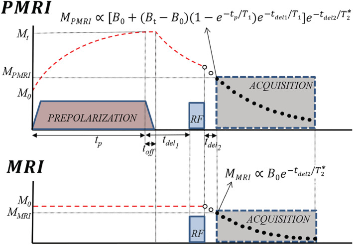
PMRI (top) and MRI (bottom) pulse sequences used in this work, with analytical expressions for the magnetization at the start of FID acquisition. Their ratio represents the SNR gain due to prepolarization, as per Equation (2). and are the magnetizations in thermal equilibrium with and without prepolarization and are directly proportional to and respectively. Red dashed lines represent the longitudinal magnetization. Black points represent k‐space data measured during the acquisition, while white points are not measured and lead to a gap in space
3. APPARATUS
As a result of the short timescales typical of solids, hard‐tissue prepolarization poses a significant engineering challenge to achieve fast enough times. Our solution to this follows.
The “DentMRI—Gen I” 0.26 T scanner, RF transmission and reception (Tx/Rx) coil and prepolarization modules employed for this work (see Figure 2) are described in detail elsewhere. 9 , 10 Essentially, our group has designed, built and characterized a prepolarizer coil with inductance , resistance and efficiency . The gap between the planar gradient stacks is , placing a hard boundary on the prepolarizer module size and, consequently, on the maximum achievable coil inductance. Due to geometric limitations, and to ease accessibility, we placed the prepolarizer module so that is perpendicular to . 10 This reduces the maximum achievable from to , but has the advantage that the generated eddy currents and the residual energy in the prepolarization coil barely disturb the longitudinal field (e.g., when falls to 1 mT, the total field deviates from the original by only 2 μT).
FIGURE 2.
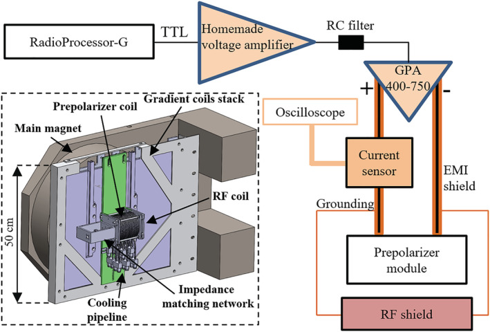
Schematic and CAD of the setup employed for hard‐tissue PMRI. Further details of the apparatus are provided in References 9 , 10
In order to cope with the short of hard biological tissues, the high‐power electronics setup for the prepolarizer module has been substantially upgraded with respect to the system introduced in Reference 10 . In the current apparatus, a digital output from the RadioProcessor‐G board (SpinCore Electronics) is amplified in two stages, first in a home‐made variable‐gain low‐voltage amplifier, and then in a high‐power (400 A and 750 V) gradient power amplifier from International Electric Co. (GPA 400‐750). The latter can ramp currents from 0 to ±260 A in about in our approximately load, where we were previously limited to about . 10 Figure 3 also shows a smoother transition corresponding to the case where we low‐pass filter the digital output with an RC circuit of characteristic time constant approximately . We have found this necessary to avoid significant mechanical displacements in the module due to the sudden appearance of strong magnetic interactions between the main magnet and the prepolarizer. This also reduces the generation of eddy currents and, thereby, distortions in the acquired signals and image reconstructions due to uncontrolled magnetic field dynamics. All the measurements below are with the low‐pass filter.
FIGURE 3.
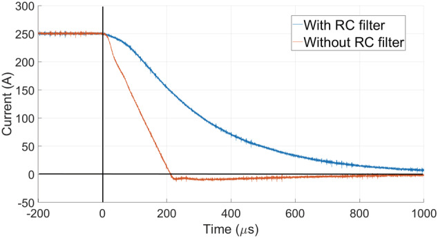
Falling edge of the prepolarization pulse current from 250 A ( T) with the GPA 400‐750, with and without the low‐pass RC filter. With the RC filter, the prepolarizer field is 15.6 mT after approximately 1 ms (1 mT at approximately 1.73 ms)
4. SNR ENHANCEMENT
For calibration and first tests we employed a sample made of a photopolymer resin, 25 which is highly homogeneous, abundant in hydrogen and features relaxation parameters comparable to the enamel in human teeth. At our , we have measured ms and with inversion recovery 26 and CPMG 27 , 28 pulse sequences, respectively.
In a first set of experiments we check whether the SNR is enhanced by prepolarization as predicted by the model in Equation (2). To this end, we set ms ( ) in the sequence in Figure 6 to prepolarize close to the saturation magnetization. Next, a resonant RF pulse coherently rotates the magnetization to the transverse plane (RF pulse time , with amplitude ). The two pulses are separated by a wait time , longer than strictly required to switch off, to avoid Larmor frequency shifts and distortions in the acquired free induction decay (FID) signals due to residual magnetic energy in the setup. The signal readout starts after the RF pulse to avoid ring‐down from the RF coil. The resulting FID is acquired for ms with a readout bandwidth kHz. This protocol is repeated for four different voltage gains of our home‐made amplifier, generating , 0.29, 0.40 and 0.49 T, which correspond to , 0.39, 0.47 and 0.56 T. Figure 4 shows the absolute values of the FIDs for these cases and for the standard MRI sequence ( and T). For a given value of , we estimate the prepolarization boost as the mean ratio of the PMRI and standard MRI data:
| (3) |
where is the signal amplitude measured for the PMRI with prepolarization strength for the time bin , and is the amplitude measured for the standard MRI sequence at . The values of estimated by this procedure are and for the above prepolarization field strengths, where the given uncertainties indicate the standard error of the mean
| (4) |
FIGURE 6.
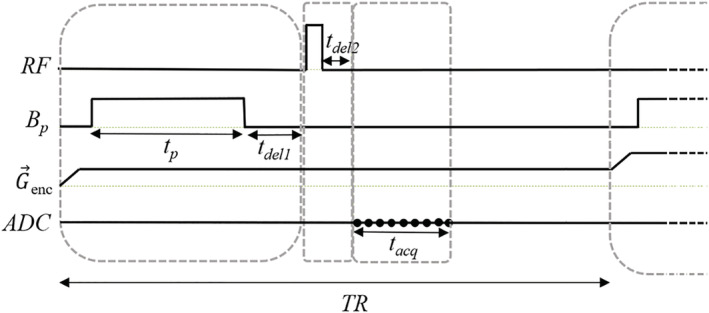
P‐PETRA pulse sequence integrating the PMRI sequence in Figure 1 with PETRA. P‐PETRA is employed for the prepolarized hard‐tissue images in Figs. 7 and 8. Here, represents the (radial or pointwise) encoding gradient, and the ADC (analog‐to‐digital converter) acquisition is marked with black points. For pointwise encoding, only the first point in the acquisition is used
FIGURE 4.
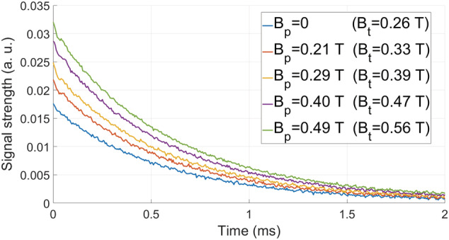
FIDs after prepolarizing the photopolymer resin sample with pulses of ms and for different values
The corresponding theoretical values for ms can be calculated from Equation (2): α ≈ 1.24, 1.44, 1.72 and 1.98.
The small experimental deviations from the theoretically calculated values could arise from (i) mechanical vibrations due to magnetic forces, (ii) induced eddy currents, (iii) off‐resonant spin evolution due to a time‐dependent Larmor frequency or (iv) dependence of on . All four are more pronounced for intense values and short times. To find a working regime where these effects are suppressed, we have characterized their influence on the SNR gain with the measurements shown in Figure 5.
FIGURE 5.
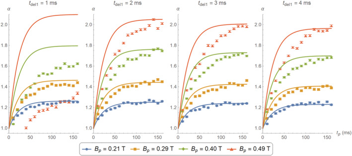
Comparison between theoretical (continuous curves) and experimentally estimated (data points) gain for different values of and , using the photopolymer resin sample. The data for T and ms are heavily corrupted by the sharp magnetic transitions. The experimental data for the stronger seem to grow more slowly than the corresponding theoretical curves, consistent with longer at higher field strengths
For the plots in Figure 5 we sweep the prepolarization pulse duration from to 160 ms and from 1 to 4 ms, for the same four values as above. The gain and uncertainty for every data point are estimated according to Equations (3) and (4). The solid lines in the figure correspond to calculations employing the model in Equation (2).
Unsurprisingly, for the weaker prepolarization currents we measure FID curves that follow closely theoretical predictions, even for as short as 1 ms. Deviations are stronger for short wait and prepolarization times. In the extreme case of T and ms, the measured data were heavily corrupted and did not follow the typical exponential behavior (i.e., as in the FIDs in Figure 4). Moreover, the curve for T is lower for ms than for ms. It is unlikely that these issues are due to drifts in the Larmor frequency as the prepolarizer relaxes, since a residual orthogonal field perturbs very weakly (e.g., for T and ms, the Larmor frequency shifts by only 250 Hz). On the other hand, eddy currents and especially mechanical vibrations could be behind the aforementioned deviations. In fact, we have observed that these unwanted effects are more prominent if the prepolarizer is not rigidly fixed to the scanner. With the mechanical fixation in place (see Figure 2), the system performs well away from this extreme regime. A further deviation from theory occurs for higher values, probably because at these fields is higher than the one we have measured at . All in all, the plots in Figure 5 demonstrate that the measured SNR gain is compatible with theoretical predictions for prepolarization pulses longer than 120 ms and ms.
5. HARD TISSUE PMRI
In this section we demonstrate the system's capability for imaging hard biological tissues with PMRI. To this end, we employ (i) an adult human molar tooth (Figure 7(c)) extracted one year before these experiments and dried so that primarily mineralized matter (dentin and enamel) remains and (ii) a piece of cattle rib (Figure 8(c)) including cortical and spongy bone tissues. We have measured the times of both samples by inversion recovery at in our system, and found and 19.3 ms for the tooth and bone, respectively. Using CPMG we have obtained and . The cattle bone contains both cortical and spongy tissues, so the estimated is an averaged quantity. The times of all the employed samples are very similar, so we can determine suitable parameter regimes from the measurements on the photopolymer resin (Figure 5).
FIGURE 7.
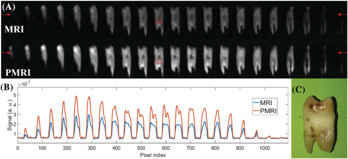
A, PETRA (top) and P‐PETRA (bottom) images of an ex vivo adult human molar tooth. B, Signal intensity along the horizontal line defined by the red arrows in A. The experimentally obtained value for the prepolarization gain is (expected value ). C, Photograph of the sample
FIGURE 8.
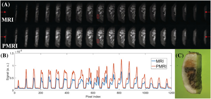
A, PETRA (top) and P‐PETRA (bottom) images of an ex vivo piece of cattle rib bone. B, Signal intensity along the horizontal line defined by the red arrows in A. The experimentally obtained value for the prepolarization SNR gain is (expected value ). C, Photograph of the sample
The ultra‐short times typical of hard tissues impose the use of dedicated MRI sequences, such as those in the zero echo time (ZTE) family. 29 These are characterized by radial k‐space acquisitions beginning immediately after the RF excitation, to capture as much as possible of the short‐lived signal. Ramping the gradient is time consuming, so in ZTE sequences the spatial encoding gradients are switched on before the RF pulse. In this work, we even switch on the frequency encoding gradient before prepolarization 30 to limit mechanical vibrations and the influence of eddy currents during data acquisition. Having the gradient on during resonant excitation imposes the use of hard (short and intense) RF pulses, leading to spurious signals, which could corrupt the data acquisition. To prevent this, we introduce a delay before the readout, resulting in a gap without data at the center of space. This can be filled with additional acquisitions. 31 One possibility is to do so in a pointwise fashion, as in PETRA (pointwise encoding time‐reduction with radial acquisition 32 ). For the following images we employ a PETRA sequence with a prepolarization stage before the RF excitation (P‐PETRA, Figure 6).
In Figure 7 we show prepolarized images of a human molar tooth obtained following the scheme in Figure 6. The size of the field of view is set to and the image is reconstructed with algebraic reconstruction techniques (ARTs 9 , 33 , 34 ) into voxels. The acquisition has a bandwidth , it starts after the RF pulse ( ) to avoid the effect of ring‐down and it lasts . The repetition time is set to , limited by the maximum duty cycle of the GPA 400‐750 at this current regime. We use 446 radial spokes for each of the 16 vertical planes, corresponding to a total k‐space undersampling factor † of ≈ 8 with respect to the Nyquist criterion, where ART reconstructions are still robust, with 136 single Cartesian points in the center. Every image contains 12 averages for a total scan time of approximately 29 min. The bottom row of images in Figure 7A corresponds to scans in which a prepolarization pulse is triggered with a current intensity of approximately 260 A ( ), which lasts ms and where . The pulse sequence for the top row of Figure 7A is identical, but the prepolarization pulse is not triggered ( T). The brightness scale is common to the two datasets. Both images have been denoised using a block‐matching filter. 9 , 35 To quantify the influence of prepolarization, we plot in Figure 7B the same profile along a horizontal line around the upper portion of the images in A, in the region of the tooth crown. We estimate the prepolarization boost as the ratio , which we average over a region of interest of constant bright pixels around the dentin before filtering (red boxes in Figure 7A). This yields approximately 1.94, where , and (analogously defined) is approximately 11.84. The mean signal and noise values ( and ) are estimated, respectively, as the mean value and standard deviation of the voxel brightness in these regions. For comparison, the expected prepolarization gain from Equation (2) is approximately 2.02.
We have applied an analogous protocol to image a piece of a cattle rib bone. The size of the field of view is set to and the image is reconstructed with ART into voxels. The acquisition starts after the RF pulse and lasts , with a bandwidth . The repetition time is . The k‐space undersampling factor is again approximately 8 (870 radial spokes, 18 vertical planes, 176 Cartesian central points). Every image contains 11 averages for a total scan time of approximately 53 min. The bottom row of images in Figure 8A corresponds to scans in which a prepolarization pulse is triggered with a current intensity of approximately 260 A ( T), which lasts ms and where . The pulse sequence for the top row of Figure 8A is identical, but the prepolarization pulse is not triggered ( T). The ratio yields approximately 1.97, where and (defined as in the previous paragraph). The expected prepolarization gain from Equation (2) is approximately 2.00.
6. DISCUSSION
The preliminary results shown in this work have been obtained in a highly constrained setup in terms of prepolarizer alignment, hydraulic capacity and prepolarizer duty cycle. If the prepolarization field had been aligned with the main static field, we could have approached T, leading to an increase in SNR of . Also, limitations in the cooling system forced us to work under 260 A, although the system could have taken up to 320 A. This corresponds to T with the crossed configuration or T if and are aligned. In this last situation, we could achieve compared to with the actual setup, resulting in a 2.4‐fold time reduction for same SNR. On the other hand, working with a prepolarizer field perpendicular to can be beneficial for faster switching off of and to reduce eddy currents, even if the total is lower. Thus, the benefits of an aligned configuration will largely depend on the ability to reduce eddy currents and to perform a well controlled switch‐off of .
A further limitation of our setup is the maximum duty cycle of the GPA 400‐750 module, which enforces repetition times . These are significantly longer than strictly required by the values of the samples. Assuming a hypothetical , enough to thermalize at ≈98% of the longitudinal magnetization, the could be shortened to around 80 ms for PMRI of teeth (actually, slightly longer due to the increased time). Increasing the duty cycle can be achieved, for example, by custom fabrication of an efficient cooling system for the high‐power gradient amplifier, as compared with the fan‐based cooling in our GPA module. This can transfer the total SNR boost into a net gain in SNR per unit time, which is the relevant metric. Taking the example of the human molar tooth and our present setup, a duty cycle defined by instead of 250 ms would translate to the same SNR gain in only approximately 9 min (three times faster). All in all, the combination of prepolarizing at 320 A, and ms can shorten the acquisition from 29 to less than 4 min for the image in Figure 7.
Finally, in order to provide a fairer comparison, we could have shortened the MRI sequence by . However, if we disregard regimes exploiting steady‐state magnetization to shorten the (which is not possible with PMRI), the standard MRI sequence must include a time for thermalization similar to the prepolarization pulse duration. Hence, the two sequences would be comparably long and a prepolarized setup with an optimal duty cycle could lead to a match between and the real SNR boost per unit time.
7. CONCLUSION AND OUTLOOK
We have demonstrated that it is possible to enhance the quality of magnetic resonance images of hard tissues at low field strengths by means of a high‐power prepolarizer module, for a total cost of approximately 20 k€, where the GPA 400‐750 module is around 13 k€. The major challenges we have faced are (i) integrating a high‐power drive capable of switching off the prepolarization pulse fast enough and (ii) coping with mechanical vibrations due to the strong magnetic interaction between the main and prepolarization fields. We have shown SNR enhancements for ex vivo imaging of a human molar tooth (29 min) and a cattle rib bone (53 min) by a factor of approximately 2, although a low duty cycle in the high‐power gradient amplifier did not allow us to translate this gain into a real boost in SNR per unit time. Nevertheless, a more efficient dissipation of the heat from the power electronics could lead to a significantly higher duty cycle and therefore to PMRI within shorter scan times.
The results in this paper could be of potential application to clinical dental MRI. While X‐rays are commonplace in dental clinics, it is known that they can increase the risk of meningioma and other cancers if performed often. 36 , 37 , 38 In fact, in recommending X‐rays, dentists follow the ALARA principle (as low as reasonably achievable), in direct conflict with medical practice, which would recommend diagnosis and medium‐term monitoring as much as required. 39 There is, hence, a clear motivation for advances in MRI that aim to replace scanners based on ionizing radiation. Standard (high‐field) MRI has proven useful for dentistry, but is too costly for massive use, 40 and often impractical due to artifacts induced by the magnetic susceptibility of metallic implants. 41 Both problems can be a priori overcome in low‐field systems, but the only experimental evidence so far has required excessively long acquisition times. 9 Hard‐tissue PMRI may be a first step towards viable dental MRI. In Section 5 we have demonstrated dental PMRI in 29 min acquisitions. This can be sped up by a factor of 3 or more in our setup with more powerful water cooling for the high‐current amplifier (see Section 6), bringing it to scan times under 10 min, albeit in a field of view significantly smaller than a full human jaw. Realistic PMRI in dental practice would seemingly require a combination of techniques, yet to be demonstrated, which could include slice‐selective ZTE sequences, 22 hybrid filling of the dead‐time gap in ZTE, 42 intra‐oral RF detection coils, 43 or acceleration schemes based on k‐space undersampling, 44 besides exquisite engineering, for scan‐time reduction. This constitutes a formidable technical challenge, but holds the promise of safe dental imaging with the added value of soft‐tissue visualization.
AUTHOR CONTRIBUTIONS
The high‐power electronics for prepolarization were designed and installed by JMG, JB, JPR and JA. The prepolarizer and mechanical holder were designed, assembled and characterized by JPR, JMG, EP and JB, with contributions from DG‐R and JA. Experimental data in the “DentMRI—Gen I” scanner were taken by JB and JMG, with help from JMA, FG, RP and JA. Data analysis was performed by JB and JMG, with input from JMA, FG, RP and JA. Animal handling and manipulation of biological tissues were performed by JB. The paper was written by JB, FG and JA, with input from all authors. Experiments were conceived by JMB, JA and AR.
ETHICAL APPROVAL
All animal parts were obtained from a local butcher and research was conducted following the 3R principles. Experiments using human teeth were approved by the medical center Clínica Llobell Cortell S.L. Procedures were conducted following the approved protocols, and informed consent was obtained from participants prior to study commencement.
CONFLICTS OF INTEREST
JB, JMA, FG, JMB and JA have patents pending that are licensed to Tesoro Imaging S.L. JMB is a co‐founder of Tesoro Imaging S.L. JB, JMG, JPR, RB, DG‐R and AR are research scientists and engineers at Tesoro Imaging S.L. All other authors declare no competing interests.
ACKNOWLEDGMENTS
This work was supported by the Ministerio de Ciencia e Innovación of Spain through research grant PID2019‐111436RB‐C21. Action co‐financed by the European Union through the Programa Operativo del Fondo Europeo de Desarrollo Regional (FEDER) of the Comunitat Valenciana 2014–2020 (IDIFEDER/2018/022). JMG and JB acknowledge support from the Innodocto program of the Agencia Valenciana de la Innovación (INNTA3/2020/22 and INNTA3/2021/17).
Borreguero Morata J, González JM, Pallás E, et al. Prepolarized MRI of hard tissues and solid‐state matter. NMR in Biomedicine. 2022;35(8):e4737. doi: 10.1002/nbm.4737
JB and JMG contributed equally to this work.
Funding information Agència Valenciana de la Innovació; European Regional Development Fund; Ministerio de Ciencia e Innovación; This work was supported by the Ministerio de Ciencia e Innovación of Spain through research grant PID2019‐111436RBC21. Action co‐financed by the European Union through the Programa Operativo del Fondo Europeo de Desarrollo Regional (FEDER) of the Comunitat Valenciana 2014‐2020 (IDIFEDER/2018/022). JMG and JB acknowledge support from the Innodocto program of the Agencia Valenciana de la Innovación (INNTA3/2020/22 and INNTA3/2021/17); Ministerio de Ciencia e Innovación of Spain, Grant/Award Number: PID2019‐111436RB‐C21; Programa Operativo del Fondo Europeo de Desarrollo Regional (FEDER) of the Comunitat Valenciana, Grant/Award Number: IDIFEDER/2018/022; Innodocto program of the Agencia Valenciana de la Innovación, Grant/Award Numbers: INNTA3/2020/22, INNTA3/2021/17
Footnotes
The undersampling factor here is defined as the ratio of outermost k‐space cell areas in the Nyquist and undersampled cases.
DATA AVAILABILITY STATEMENT
The data that support the findings of this study are available from the corresponding author upon reasonable request.
REFERENCES
- 1. Sarracanie M, LaPierre CD, Salameh N, Waddington DEJ, Witzel T, Rosen MS. Low‐cost high‐performance MRI. Sci Rep. 2015;5(1):15177. https://www.nature.com/articles/srep15177 [DOI] [PMC free article] [PubMed] [Google Scholar]
- 2. Marques JP, Simonis FF, Webb AG. Low‐field MRI: an MR physics perspective. J Magn Reson Imaging. 2019;49(6):1528‐1542. doi: 10.1002/jmri.26637 [DOI] [PMC free article] [PubMed] [Google Scholar]
- 3. Sarracanie M, Salameh N. Low‐field MRI: how low can we go? A fresh view on an old debate. Front Phys. 2020;8:172. doi: 10.3389/fphy.2020.00172/full [DOI] [Google Scholar]
- 4. Macovski A, Conolly S. Novel approaches to low‐cost MRI. Magn Reson Med. 1993;30(2):221‐230. [DOI] [PubMed] [Google Scholar]
- 5. Morgan P, Conolly S, Scott G, Macovski A. A readout magnet for prepolarized MRI. Magn Reson Med. 1996;36(4):527‐536. doi: 10.1002/mrm.1910360405 [DOI] [PubMed] [Google Scholar]
- 6. Kegler C, Seton H, Hutchison J. Prepolarized fast spin‐echo pulse sequence for low‐field MRI. Magn Reson Med. 2007;57(6):1180‐1184. doi: 10.1002/mrm.21238 [DOI] [PubMed] [Google Scholar]
- 7. Lee SK, Moessle M, Myers W, et al. MRI: SQUID‐detected at 132 T with contrast established at 10 T–300 mT. Magn Reson Med. 2005;53(1):9‐14. doi: 10.1002/mrm.20316 [DOI] [PubMed] [Google Scholar]
- 8. Obungoloch J, Harper JR, Consevage S, et al. Design of a sustainable prepolarizing magnetic resonance imaging system for infant hydrocephalus. Magn Reson Mater Phys Biol Med. 2018;31(5):665‐676. doi: 10.1007/s10334-018-0683-y [DOI] [PMC free article] [PubMed] [Google Scholar]
- 9. Algarín JM, Díaz‐Caballero E, Borreguero J, et al. Simultaneous imaging of hard and soft biological tissues in a low‐field dental MRI scanner. Sci Rep. 2020;10(1):21470. doi: 10.1038/s41598-020-78456-2 [DOI] [PMC free article] [PubMed] [Google Scholar]
- 10. Rigla JP, Borreguero J, Gramage C, et al. A fast 0.5 T prepolarizer module for preclinical magnetic resonance imaging. IEEE Trans Magn. 2021;58:5100208. [Google Scholar]
- 11. Kowalewski J, Mäler L. Nuclear Spin Relaxation in Liquids: Theory, Experiments, and Applications. Taylor & Francis; 2006. [Google Scholar]
- 12. Matter N, Scott G, Grafendorfer T, Macovski A, Conolly S. Rapid polarizing field cycling in magnetic resonance imaging. IEEE Trans Med Imaging. 2006;25(1):84‐93. https://ieeexplore.ieee.org/document/1564329/ [DOI] [PubMed] [Google Scholar]
- 13. Matter NI, Scott GC, Venook RD, Ungersma SE, Grafendorfer T, Macovski A, Conolly SM. Three‐dimensional prepolarized magnetic resonance imaging using rapid acquisition with relaxation enhancement. Magn Reson Med. 2006;56:1085‐1095. http://www.interscience.wiley.com [DOI] [PubMed] [Google Scholar]
- 14. Venook RD, Matter NI, Ramachandran M, et al. Prepolarized magnetic resonance imaging around metal orthopedic implants. Magn Reson Med. 2006;56(1):177‐186. doi: 10.1002/mrm.20927 [DOI] [PubMed] [Google Scholar]
- 15. Savukov I, Karaulanov T. Magnetic‐resonance imaging of the human brain with an atomic magnetometer. Appl Phys Lett. 2013;103(4):43703. doi: 10.1063/1.4816433 [DOI] [PMC free article] [PubMed] [Google Scholar]
- 16. Inglis B, Buckenmaier K, Sangiorgio P, Pedersen AF, Nichols MA, Clarke J. MRI of the human brain at 130 microtesla. Proc Natl Acad Sci U S A. 2013;110(48):19194‐19201. https://www.ncbi.nlm.nih.gov/pubmed/24255111, http://www.pubmedcentral.nih.gov/articlerender.fcgi%3Fartid=PMC3845112 [DOI] [PMC free article] [PubMed] [Google Scholar]
- 17. Duer MJ. Introduction to Solid‐State NMR Spectroscopy. Oxford: Blackwell; 2004. [Google Scholar]
- 18. Weiger M, Wu M, Wurnig MC, et al. Selective musculoskeletal MRI using ZTE imaging with long‐T2 suppression. Proc Int Soc Magn Reson Med. 2015;23:941. [Google Scholar]
- 19. de Mello RAF, jun Ma Y, Ashir A, et al. Three‐dimensional zero echo time magnetic resonance imaging versus 3‐dimensional computed tomography for glenoid bone assessment. Arthroscopy. 2020;36(9):2391‐2400. [DOI] [PMC free article] [PubMed] [Google Scholar]
- 20. Seifert AC, Li C, Wilhelm MJ, Wehrli SL, Wehrli FW. Towards quantification of myelin by solid‐state MRI of the lipid matrix protons. NeuroImage. 2017;163:358‐367. [DOI] [PMC free article] [PubMed] [Google Scholar]
- 21. Bae K, Jeon KN, Hwang MJ, et al. Respiratory motion‐resolved four‐dimensional zero echo time (4D ZTE) lung MRI using retrospective soft gating: feasibility and image quality compared with 3D ZTE. Eur Radiol. 2020;30(9):5130‐5138. doi: 10.1007/s00330-020-06890-x [DOI] [PubMed] [Google Scholar]
- 22. Borreguero J, Galve F, Algarín JM, Benlloch JM, Alonso J. Slice‐selective zero echo time imaging of ultra‐short T2 tissues based on spin‐locking. arXiv preprint, p. 2201.06305; 2022.
- 23. Weiger M, Pruessmann KP, Bracher A‐K, et al. High‐resolution ZTE imaging of human teeth. NMR Biomed. 2012;25(10):1144‐1151. doi: 10.1002/nbm.2783 [DOI] [PubMed] [Google Scholar]
- 24. Hiller T, Dlugosch R, Müller‐Petke M. Utilizing pre‐polarization to enhance SNMR signals—effect of imperfect switch‐off. Geophys J Int. 2020;222(2):815‐826. doi: 10.1093/gji/ggaa [DOI] [Google Scholar]
- 25. Rai R, Manton D, Jameson M, et al. 3D printed phantoms mimicking cortical bone for the assessment of ultrashort echo time magnetic resonance imaging. Med Phys. 2017;45:12. [DOI] [PubMed] [Google Scholar]
- 26. Bydder GM, Hajnal JV, Young IR. MRI: use of the inversion recovery pulse sequence. Clin Radiol. 1998;53(3):159‐176. [DOI] [PubMed] [Google Scholar]
- 27. Carr HY, Purcell EM. Effects of diffusion on free precession in nuclear magnetic resonance experiments. Phys Rev. 1954;94(3):630‐638. [Google Scholar]
- 28. Meiboom S, Gill D. Modified spin‐echo method for measuring nuclear relaxation times. Rev Sci Instrum. 1958;29(8):688‐691. [Google Scholar]
- 29. Weiger M, Brunner DO, Dietrich BE, Müller CF, Pruessmann KP. ZTE imaging in humans. Magn Reson Med. 2013;70(2):328‐332. doi: 10.1002/mrm.24816 [DOI] [PubMed] [Google Scholar]
- 30. Kobayashi N, Goerke U, Wang L, Ellermann J, Metzger GJ, Garwood M. Gradient‐modulated PETRA MRI. Tomography. 2015;1(2):85‐90. https://www.mdpi.com/2379-139X/1/2/85 [DOI] [PMC free article] [PubMed] [Google Scholar]
- 31. Weiger M, Pruessmann KP. Short‐T2 MRI: principles and recent advances. Prog Nucl Magn Reson Spectrosc. 2019;114‐115:237‐270. [DOI] [PubMed] [Google Scholar]
- 32. Grodzki DM, Jakob PM, Heismann B. Ultrashort echo time imaging using pointwise encoding time reduction with radial acquisition (PETRA). Magn Reson Med. 2012;67(2):510‐518. [DOI] [PubMed] [Google Scholar]
- 33. Karczmarz S. Angenäherte auflösung von systemen linearer gleichungen. Bull Int Acad Pol Sic Let Cl Sci Math Nat. 1937:355‐357. https://ci.nii.ac.jp/naid/10009398882/en/ [Google Scholar]
- 34. Gower RM, Richtarik P. Randomized iterative methods for linear systems. SIAM J Matrix Anal Appl. 2015;36(4):1660‐1690. [Google Scholar]
- 35. Maggioni M, Katkovnik V, Egiazarian K, Foi A. Nonlocal transform‐domain filter for volumetric data denoising and reconstruction. IEEE Trans Image Process. 2013;22(1):119‐133. [DOI] [PubMed] [Google Scholar]
- 36. Claus EB, Calvocoressi L, Bondy ML, Schildkraut JM, Wiemels JL, Wrensch M. Dental x‐rays and risk of meningioma. Cancer. 2012;118(18):4530‐4537. doi: 10.1002/cncr.26625 [DOI] [PMC free article] [PubMed] [Google Scholar]
- 37. Memon A, Rogers I, Paudyal P, Sundin J. Dental x‐rays and the risk of thyroid cancer and meningioma: a systematic review and meta‐analysis of current epidemiological evidence. Thyroid. 2019;29(11):1572‐1593. doi: 10.1089/thy.2019.0105 [DOI] [PubMed] [Google Scholar]
- 38. Chauhan V, Wilkins RC. A comprehensive review of the literature on the biological effects from dental X‐ray exposures. Int J Radiat Biol. 2019;95(2):107‐119. doi: 10.1080/09553002.2019.1547436 [DOI] [PubMed] [Google Scholar]
- 39. Jaju PP, Jaju SP. Cone‐beam computed tomography: time to move from ALARA to ALADA. Imaging Sci Dent. 2015;45(4):263‐265. doi: 10.5624/isd.2015.45.4.263 [DOI] [PMC free article] [PubMed] [Google Scholar]
- 40. Mastrogiacomo S, Dou W, Jansen JA, Walboomers XF. Magnetic resonance imaging of hard tissues and hard tissue engineered bio‐substitutes. Mol Imaging Biol. 2019;21(6):1003‐1019. doi: 10.1007/s11307-019-01345-2 [DOI] [PubMed] [Google Scholar]
- 41. Gao X, Wan Q, Gao Q. Susceptibility artifacts induced by crowns of different materials with prepared teeth and titanium implants in magnetic resonance imaging. Sci Rep. 2022;12(1):428. https://www.nature.com/articles/s41598-021-03962-w [DOI] [PMC free article] [PubMed] [Google Scholar]
- 42. Froidevaux R, Weiger M, Rösler MB, Brunner DO, Pruessmann KP. HYFI: hybrid filling of the dead‐time gap for faster zero echo time imaging. NMR Biomed. 2021;34(6):e4493. doi: 10.1002/nbm.4493 [DOI] [PMC free article] [PubMed] [Google Scholar]
- 43. Ludwig U, Eisenbeiss AK, Scheifele C, et al. Dental MRI using wireless intraoral coils. Sci Rep. 2016;6. [DOI] [PMC free article] [PubMed] [Google Scholar]
- 44. Lustig M, Donoho D, Pauly JM, Sparse MRI. The application of compressed sensing for rapid MR imaging. Magn Reson Med. 2007;58(6):1182‐1195. doi: 10.1002/mrm.21391 [DOI] [PubMed] [Google Scholar]
Associated Data
This section collects any data citations, data availability statements, or supplementary materials included in this article.
Data Availability Statement
The data that support the findings of this study are available from the corresponding author upon reasonable request.


