

Abstract
Background:
Current laparoscopic surgical robots are teleoperated, which requires high fidelity differential motions but does not require absolute accuracy. Emerging applications, including image guidance and automation, require absolute accuracy. The absolute accuracy of the da Vinci Xi robot has not yet been characterized or compared to the Si system, which is now being phased out. This paper compares the accuracy of the two.
Methods:
We measure robot tip positions and encoder values assessing accuracy with and without robot calibration.
Results:
The Si is accurate if the setup joints are not moved but loses accuracy otherwise. The Xi is always accurate.
Conclusion:
The Xi can achieve submillimetric average error. Calibration improves accuracy, but excellent baseline accuracy of the Xi means that calibration may not be needed for some applications. Importantly, the external tracking systems needed to account for setup joint error in the Si are no longer required with the Xi.
Keywords: Image-Guided Surgery, Surgical Automation, Surgical Robot Calibration, Surgical Robotics
1. Introduction
Robot-assisted surgical procedures with the da Vinci Surgical System (Intuitive Surgical Inc., Sunnyvale, CA) have steadily increased over the past two decades. The da Vinci system has become a widely adopted robotic tool in minimally invasive surgical procedures1,2 with application in urology, cardiology, colorectal surgery, gynecology, and head and neck surgery3. The system increases dexterity4 and improves the surgeon’s ergonomics and efficiency5. In 2018, approximately 1,037,000 surgeries were performed using the da Vinci system (an increase of 18% compared to 2017)6. Currently, the da Vinci system functions as a teleoperator, where the surgeon’s motions are mapped directly to tool motions inside the patient. Teleoperation requires good differential motion capabilities so that the tool tip moves in the surgeon’s intended direction.
However, many advanced capabilities have been envisioned for robots like the da Vinci where the fidelity of differential motions alone would not be enough, and absolute accuracy will be required. For example, robotic automation of surgical tasks and subtasks often relies on an accurate kinematic model7–13. Other automation methods currently rely on visual servoing to close the loop on positional errors14–18, but kinematic model accuracy will be useful in the future if 3D medical image information is ever to be integrated into automation—something that will undoubtedly be needed in some surgical contexts. It is also likely that kinematic model accuracy will be useful for surgical skill evaluation19–22 in the future as the instruments’ proximity to various anatomical features is incorporated into skill metrics. Another application that often requires excellent absolute accuracy is image guidance using registered, medical images23–35.
Researchers have previously explored the absolute accuracy of the da Vinci Classic and the da Vinci S surgical systems36,37. The accuracy of these systems enabled image guidance when considering the motorized, active kinematic chain of the da Vinci. However, the full kinematic chain (which consists of the passive setup joints as well as the motorized active joints) of the da Vinci S was not accurate enough for image guidance. Thus, a “hybrid tracking” approach was developed where the base frame of the active joints was measured by an optical tracking system in order to bypass the setup joints38. Results from these accuracy studies formed the foundation of many image guidance applications using the da Vinci instruments as localizers39–47.
There are a number of important advancements described in this paper with respect to prior work on the use of the da Vinci system for image guidance. While baseline accuracy has been characterized for the older da Vinci Classic36 and S37 systems, and our group has partially calibrated the Si system48, calibration has never previously been reported for the newer Xi system. Similarly, the Xi system’s accuracy (whether calibrated or not) has never been previously compared to that of the Si system, a comparison that is timely since the Si is currently being phased out in favor of the newer Xi at hospitals worldwide, as discussed further below. Furthermore, the setup joints have not been included in past analyses, other than to note that they are much less accurate than the active joints and should be omitted from image guidance altogether38. We include a thorough accuracy analysis and calibration of the setup joints and reach the useful (and somewhat surprising) conclusion that the Xi system’s setup joints are so accurate that they can be seamlessly integrated into image guidance. We also approach data collection differently from past work, using a tracked pointer rather than rigid objects, which eliminates tool deformation as a potentially confounding factor. By streamlining the data acquisition process in this way, we were also able to collect more data points (100) than the previous studies (11), which enabled rigorous cross-validation to characterize accuracy before and after robot calibration.
All prior clinical image guidance and automation research has been conducted on the da Vinci Classic, S, and Si systems. However, the Classic and S systems have already been phased out, and the Si is currently in the process of being phased out in favor of the newer Xi platform. In 2019, Intuitive shipped 848 da Vinci Xi systems to hospitals while only 30 da Vinci Si systems were shipped49. Thus, it is important to understand how research results developed on prior systems might relate to the newer Xi system, which has a differing kinematic design. Therefore, in addition to the previously listed differences, the most fundamental difference between our accuracy study and the previous studies is the characterization of the Xi system’s accuracy and the comparison to that of the prior Si system.
This paper presents the first study of the accuracy of the da Vinci Xi and direct comparison to that of the Si. We determine the accuracy of the active as well as the full kinematic chain of both the Si and Xi using nominal model parameters. We then calibrate both the active and the full kinematic models, analyze their accuracy post-calibration, and compare the accuracy of the two systems. We show that submillimetric mean accuracy is possible with the Xi system and that the improvements to the Xi have made the setup arms so accurate that hybrid tracking with an external tracking system is no longer necessary.
2. Materials and Methods
2.1. The da Vinci Xi Robotic System
Similarly to previous generations of the da Vinci, the Xi patient cart comprises four independent serial manipulators. These Universal Surgical Manipulator (USM) arms manipulate laparoscopic surgical tools attached to their distal ends which mimic the motion of the surgeon’s hands that is input at the surgeon console.
Each USM consists of a series of setup joints (called the setup kinematic chain) and a series of active joints (called the active chain). The full kinematic chain is defined by combining the setup and active chains in series. One of the USMs of the Xi system is depicted in Figure 1. The setup joints are most proximal to the base of the patient cart and allow for manual, gross positioning of the manipulator’s Remote Center of Motion (RCM), a process most commonly performed during preoperative setup. The setup joints’ actuation axes are illustrated as the dotted arrows in Figure 1. At the distal end of each USM, the active joints provide fine, motorized movement enabling the instrument to follow the surgeon’s commands inside the patient. The active joint axes are illustrated as solid arrows in Figure 1.
Figure 1:
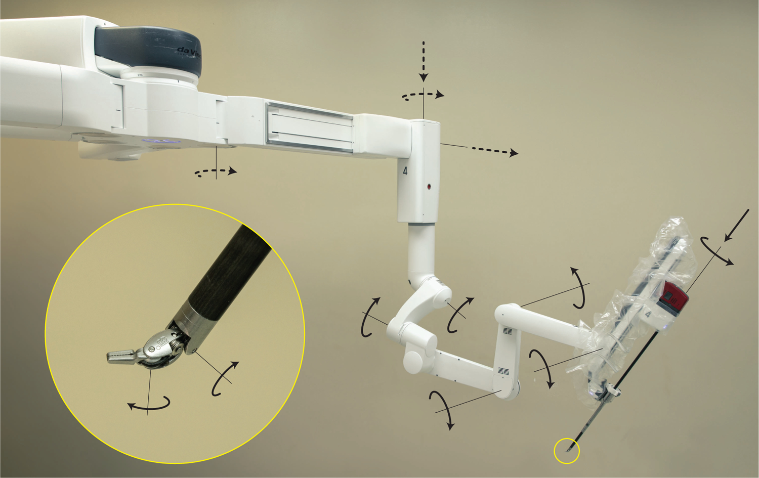
Kinematic diagram of one of the universal serial manipulators of the da Vinci Xi system. The motorless setup joints (illustrated as dotted arrows) determine the gross position of the Remote Center of Motion (RCM) and are locked during operation. The motorized active joints (solid arrows) control the pose of the instrument tip which mimics surgeon hand motion during operation.
In addition to a laser-guided port positioning system and many new safety features, much of the Xi system’s kinematic structure has been redesigned. In comparison to the older Si system, the newer Xi features smaller, thinner robotic arms with redesigned joints that enable greater range of motion. Indeed, the new patient clearance joint (the first, most proximal joint in the active chain) enables more clearance between the USM and the patient when necessary. Another design change is that the endoscope can now be manipulated by any of the four USMs. In previous da Vinci systems, there was a distinction made between surgical instrument manipulators and the endoscope manipulator. Additionally, the instruments of the Xi system have been improved to increase instrument workspace, whereas the rotational joints have been redesigned to reduce compliance.
2.2. Robot Model Accuracy Estimation
In robotic systems, kinematic models are used to describe a robot’s instrument tip position and orientation as a function of the robot system’s joint variables. For a single kinematic chain (e.g. active chain or full chain) on one of the arms of the da Vinci, the kinematic model takes the form
| (1) |
where are the n robotic joint variables, are the l kinematic parameters that describe the geometry of the robot, and is the model-predicted position of the tip of the robotic instrument measured relative to the robot’s coordinate system.
In particular, to compute the kinematics (1) of the da Vinci patient manipulators, Khalil’s modified Denevit-Hartenburg (DH) convention50 is adopted as per the da Vinci Application Programming Interface (API) user manual51. Under this convention, consecutive robot link coordinate systems are related to one another by first translating and rotating about the X axis (by the parameters a and α respectively) and then translating and rotating about the new Z axis (by d and θ)50. If the given joint is revolute, its joint value is added to θ prior to computing the kinematics of the robot; if the joint is prismatic, its value is added to d. We have included the nominal DH parameters for the da Vinci Si and Xi systems in Tables 1 and 2 respectively. These tables assume the EndoWrist Large Needle Driver instrument that we used in our experiments. Note that the model for the Si explicitly assumes a Remote Center of Motion (RCM) constraint; therefore, a constant offset is added to move from the end of the setup chain to the RCM located at the beginning of the active chain. Additionally, as a consequence of Khalil’s modified convention50, another constant offset is added to move from the final link frame to the instrument tip.
Table 1:
Denevit-Hartenburg (DH) parameters for the da Vinci Si full kinematic chain assuming a Large Needle Driver EndoWrist instrument. This model explicitly assumes a Remote Center of Motion (RCM) constraint, so a constant offset is added between the setup chain and the active chain. Another constant offset is added to move from the final link frame to the instrument tip.
| Joint Type | a (m) | α (deg) | d (m) | θ (deg) | |
|---|---|---|---|---|---|
| Setup Chain | Prismatic | 0.0000 | 0.00 | 0.1471 | 0.00 |
| Revolute | 0.0000 | 0.00 | 0.6654 | 0.00 | |
| Revolute | 0.4572 | 0.00 | 0.1397 | 0.00 | |
| Revolute | 0.4572 | 0.00 | −0.1301 | 0.00 | |
| Offset | — | 0.0490 | 90.00 | 0.0000 | 45.00 |
| — | 0.0000 | −90.00 | 0.0000 | 0.00 | |
| — | 0.8343 | 0.00 | 0.0000 | −90.00 | |
| Active Chain | Revolute | 0.0000 | 90.00 | 0.0000 | 90.00 |
| Revolute | 0.0000 | −90.00 | 0.0000 | −90.00 | |
| Prismatic | 0.0000 | 90.00 | −0.4793 | 0.00 | |
| Revolute | 0.0000 | 0.00 | 0.4670 | 0.00 | |
| Revolute | 0.0000 | −90.00 | 0.0000 | −90.00 | |
| Revolute | 0.0091 | −90.00 | 0.0000 | −90.00 | |
| Offset | — | 0.0000 | −90.00 | 0.0100 | 0.00 |
Table 2:
Denevit-Hartenburg (DH) parameters for the da Vinci Xi full kinematic chain assuming a Large Needle Driver EndoWrist instrument. Note that the constant offset is added to move from the final link frame to the instrument tip.
| Joint Type | a (m) | α (deg) | d (m) | θ (deg) | |
|---|---|---|---|---|---|
| Setup Chain | Revolute | 0.1683 | 0.00 | 0.0000 | 55.00 |
| Prismatic | −0.0203 | 90.00 | 0.6381 | 0.00 | |
| Prismatic | 0.0000 | −90.00 | −0.2687 | 0.00 | |
| Revolute | 0.0000 | 0.00 | −0.3754 | 0.00 | |
| Active Chain | Revolute | 0.0000 | 62.00 | −0.8089 | 90.00 |
| Revolute | 0.0000 | 15.00 | 0.3039 | 0.00 | |
| Revolute | −0.0273 | −87.20 | −0.0148 | −28.03 | |
| Revolute | 0.2540 | 0.00 | 0.0000 | 112.89 | |
| Revolute | 0.3048 | 0.00 | 0.0000 | 5.14 | |
| Prismatic | 0.1194 | −90.00 | −0.3379 | 0.00 | |
| Revolute | 0.0000 | 0.00 | 0.4670 | 0.00 | |
| Revolute | 0.0000 | −90.00 | 0.0000 | −90.00 | |
| Revolute | 0.0091 | −90.00 | 0.0000 | −90.00 | |
| Offset | — | 0.0000 | −90.00 | 0.0100 | 0.00 |
In surgical applications that require absolute (rather than differential) accuracy (e.g. image guidance, automation of certain surgical tasks, etc.), an accurate robot model is essential to assisting the surgeon. Robot model accuracy is defined as the difference between the predicted robot end effector pose and its true achieved pose when commanded to a particular configuration52. This definition of robot model accuracy comprises both translation and rotation errors. However, in this paper, we consider only the 3D position measurements, since our goal is ultimately to use the robot for image guidance applications and to enable automation of surgical tasks that require position accuracy. Note that in future work, if rotational accuracy is required, it can be included within the calibration framework presented in this paper following standard robotic calibration processes. Based on this, robot accuracy can be defined as the Fiducial Localization Error (FLE) which is the Euclidean distance between the model-predicted instrument tip position and the true tip position (both measured in the robot’s coordinate system):
| (2) |
Note that the term “fiducial localization error” is borrowed from the image guidance literature53. When considering positional accuracy, it is equivalent to “robot model accuracy” in the robotics literature52.
To characterize the accuracy of the da Vinci experimentally, we must measure the true tip position of the robot . Computing FLE requires expressing the instrument tip position reported by the sensor in the robot coordinate system rather than in the coordinate system of the sensor itself. The transformation relating the robot coordinate system and the sensor coordinate system can be estimated by point-based rigid registration54, but this problem is coupled to accuracy estimation.
To solve this coupled problem, instead of computing the FLE at each sample point after a point-based registration, we estimate the expected value 〈FLE2〉 directly. As is often done, we assume that the components of the FLE are independent, identically distributed, normal random variables. Given this, then the following relationship between expected values holds36,37,55:
| (3) |
where FRE is the fiducial registration error resulting from a rigid, point-based registration between N corresponding sensor measurements and model predicted points55. Thus, instead of measuring the FLE directly, we rigidly register sensor position measurements to model predicted measurements to produce 〈FRE2〉. Then we compute the standard Root-Mean-Square (RMS) FLE from (3). This method was used previously to estimate the intrinsic accuracy of the da Vinci Classic36 and the da Vinci S37 systems in the context of image guidance.
2.3. Data Acquisition for Accuracy Estimation
Given our accuracy estimation framework, it is convenient to define a measurement . For a particular robot model, sampling of m over many randomly selected robot configurations enables an analysis of robot accuracy. To sample m, the robot is first commanded to a random configuration q. The sensed tip position and the joint values q are then stored in m.
As data is collected, the samples are accumulated in a data set where M is the number of measurements. Here, we describe the data collection process that we use to determine the data sets XSi, Active, XSi, Full, XXi, Active, and XXi, Full for each of the kinematic chains of interest for the da Vinci Si and Xi, respectively. Note that the dimensionality of the measurements in these data sets differ, as each kinematic chain has a different number of joint variables n; for example, a full chain has more joints than an active chain, and the Xi has an additional active joint that the older Si does not have—the patient clearance joint.
To measure the ground truth tip position of the da Vinci instruments, we use an optically tracked rigid body with 3 tracking spheres specially designed to be grasped by the da Vinci. Its position is optically tracked by the Polaris Spectra (Northern Digital Inc.) optical tracking system which specifies an RMS accuracy of 0.25 mm for tracked rigid bodies56 (see Fig. 2). Our tracked rigid body is finely-toleranced for interfacing with the EndoWrist Large Needle Driver instrument to ensure repeatable grasping. We designed this interface between the rigid body and the robotic instrument based on CAD models of the instrument tip. We 3D printed the rigid body using a FormLabs Form 2 stereolithography printer with standard photopolymer resin. To decrease overall weight and material usage, the triangle formed by the three tracking spheres was designed to be as small as possible while still conforming to the Polaris Spectra standards for tracked rigid bodies. We used standard, reflective tracking spheres and mounting posts that we attached to our rigid body using press fit threaded inserts.
Figure 2:

Setup to collect data for analyzing the intrinsic accuracy of the da Vinci Xi and Si patient manipulators. Robot joint values are acquired using the da Vinci Application Programming Interface (API), and ground truth instrument tip position data is measured using a Polaris Spectra (Northern Digital Inc.) optical tracker.
As the sensor actually measures the pose of the rigid body (i.e. {tool} in Fig. 2), a separate pivot calibration process57 was used to determine the constant position of the tool tip relative to the tracked tool’s coordinate system. The da Vinci API51 was used to query the da Vinci Si and Xi systems for their robotic joint values q.
To sample a measurement m for a given da Vinci kinematic chain, each joint value was first moved via the surgeon interface. The tool tip position was recorded with the optical tracker, and the joint values q were recorded with the da Vinci API. These measurements together form a sample m which is appended to the data set X. This was performed M = 100 times for each of the da Vinci kinematic chains resulting in the four data sets XSi, Active, XSi, Full, XXi, Active, and XXi, Full as desired.
2.4. da Vinci Accuracy Analysis
When assessing the accuracy of a robot model, it is important to use separate data (not used for calibration) to infer accuracy post-calibration to rule out model overfitting. To this end, we use a Monte Carlo cross-validation process where X is randomly partitioned into two sets: a training set (70 samples) and an validation set (30 samples). The data are randomly partitioned in this way many times, each time calibrating the robot model with a different training set and evaluating the nominal and calibrated accuracies with the validation set. The rest of this section explains one iteration of our cross-validation process in more detail. A flowchart illustrating one iteration of the process is also provided in Figure 3. For simplification, we use a general data set X with the understanding that the following was performed for each of the four collected data sets: XSi, Active, XSi, Full, XXi, Active, and XXi, Full.
Figure 3:
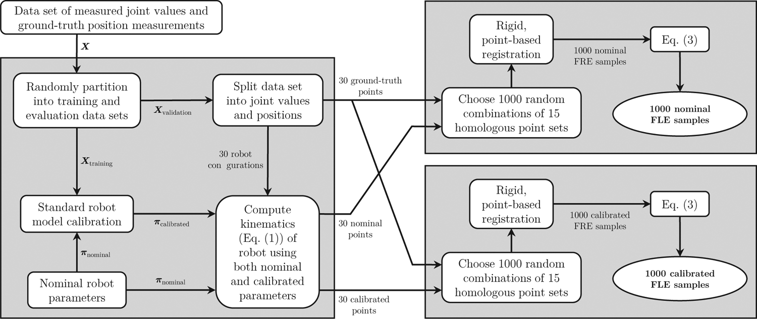
Flowchart illustrating a single iteration of our Monte Carlo cross-validation process to estimate robot accuracy. Each iteration generates 1,000 samples of FLE both with and without calibration. By running the process 100 times, we generated 100,000 samples of FLE for each of the kinematic chains from the collected data sets.
Using the validation data set, the instrument tip positions were computed with the nominal parameters πnominal to produce 30 3D validation points. This set of 30 model-predicted points was then compared to the corresponding set of 30 optically tracked, ground truth points to evaluate accuracy. Of the 30 homologous point pairs, 15 were randomly selected. These point sets were rigidly registered to produce the FRE. Using (3), the FRE is used to estimate the expected value 〈FLE2〉 from which we obtain the standard RMS FLE metric. We repeated this process 1,000 times with different random selections of 15 of the 30 points.
Using the training data set, the robot model (1) was calibrated using standard serial robot calibration techniques that assume a rigid kinematic chain58,59. Optimization over the training data produced the best vector of model parameters πcalibrated in the least squares sense. Using the validation data set and the calibrated model parameters πcalibrated, the same analysis was performed as with the nominal parameters to produce 1,000 FLE samples.
We repeated this cross-validation process 100 times. As each iteration produces 1,000 FLE samples both before and after calibration (see Fig. 3), this resulted in a total of 100,000 FLE samples before calibration and 100,000 FLE samples after calibration. Each iteration of our cross-validation process uses different subsets of the collected data points. Therefore, each of the 100 iterations that we ran represents a unique experiment where the robot was first calibrated (using unique training data) and then subsequently validated (using unique validation data).
3. Results
For each of the four da Vinci kinematic chains, histograms of both the nominal FLE (blue) and the calibrated FLE (red) are shown in Figure 4. On each of the graphs, the x axis shows the mean FLE sample values, and the y axis shows the number of FLE samples in a given bin. In all cases, calibration significantly reduced the FLE.
Figure 4:
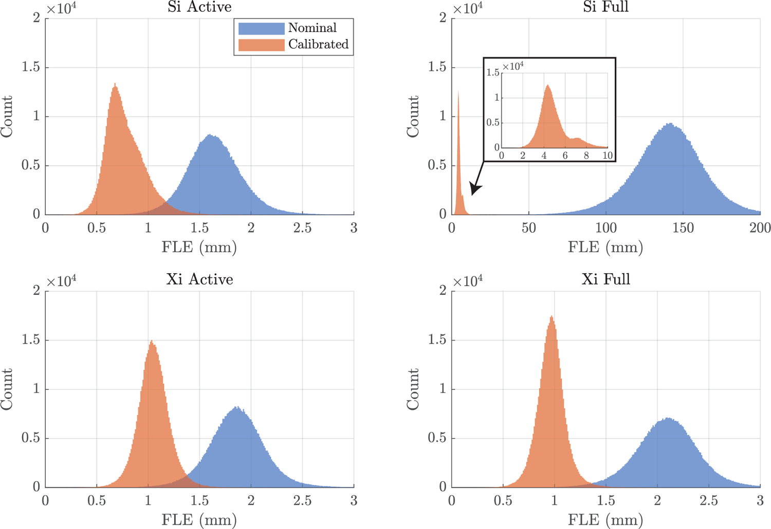
Histograms of the Fiducial Localization Error (FLE) samples for the da Vinci Si and the da Vinci Xi patient arms. The FLE is shown when considering the full kinematic chain (the active and setup joints) and when only considering the active kinematic chain for each of the two systems. In each of these cases, the FLE is shown both before (blue) and after (red) robot calibration. Note that the bin widths and axis scales are consistent in all cases excluding the Si full chain.
The mean values and standard deviations of the FLE for each kinematic chain are shown in Table 3. These statistics are also shown in a bar chart in Figure 5, where the chart on the right depicts a zoomed in view. The bars here are grouped by kinematic chain to showcase the benefit of calibration. The standard deviations of the FLE are indicated by the error bars at the top of the main bars for each accuracy estimate. Note, that the bar corresponding to the nominal mean FLE for the Si full chain has been truncated in the plot on the right.
Table 3:
Mean μ and standard deviation σ accuracy (FLE) statistics for each of the kinematic chains.
| Si Active Nominal | Si Active Calibrated | Si Full Nominal | Si Full Calibrated | Xi Active Nominal | Xi Active Calibrated | Xi Full Nominal | Xi Full Calibrated | |
|---|---|---|---|---|---|---|---|---|
| μ (mm) | 1.64 | 0.78 | 140.86 | 4.94 | 1.86 | 1.05 | 2.09 | 0.97 |
| σ (mm) | 0.27 | 0.19 | 23.10 | 1.47 | 0.28 | 0.15 | 0.31 | 0.14 |
Figure 5:

Estimated mean FLE for each of the da Vinci Si and Xi kinematic chains. The chart is shown at two scales: full scale (left) and zoomed in (right). For each kinematic chain, FLE is shown both before calibration (blue) and after calibration (red). The error bars indicate the sample standard deviation for each FLE data set. Note that the bar corresponding to the nominal FLE for the Si full chain has been truncated in the chart on the right.
A matrix showing the difference in mean between any two of the FLE data sets is shown in Table 4. The Cohen’s d effect size is also shown alongside the difference in means. The Cohen’s d effect size is a standard statistical measure of the magnitude of the difference in means of two data sets in comparison to their standard deviations. The difference in mean between any two of the eight model accuracies was significant (p << 0.05) according to a paired t test.
Table 4:
Matrix of differences in mean (mm) and corresponding Cohen’s d effect sizes (in bold) between any two of the eight accuracy data sets. All differences were significant (p << 0.05) according to a paired t test.
| Si Active Nominal | Si Active Calibrated | Si Full Nominal | Si Full Calibrated | Xi Active Nominal | Xi Active Calibrated | Xi Full Nominal | Xi Full Calibrated | |
|---|---|---|---|---|---|---|---|---|
| Si Active Nominal | 0.0 0.0 |
|||||||
| Si Active Calibrated | −0.87 −3.70 |
0.0 0.0 |
||||||
| Si Full Nominal | 139.21 8.52 |
140.08 8.57 |
0.0 0.0 |
|||||
| Si Full Calibrated | 3.30 3.13 |
4.16 3.98 |
−135.92 −8.30 |
0.0 0.0 |
||||
| Xi Active Nominal | 0.22 0.79 |
1.08 4.60 |
−139.00 −8.51 |
−3.08 −2.92 |
0.0 0.0 |
|||
| Xi Active Calibrated | −0.59 −2.67 |
0.28 1.62 |
−139.80 −8.56 |
−3.89 −3.73 |
−0.81 −3.63 |
0.0 0.0 |
||
| Xi Full Nominal | 0.45 1.53 |
1.32 5.11 |
−138.76 −8.49 |
−2.85 −2.69 |
0.23 0.79 |
1.04 4.23 |
0.0 0.0 |
|
| Xi Full Calibrated | −0.68 −3.13 |
0.19 1.17 |
−139.89 −8.56 |
−3.97 −3.82 |
−0.89 −4.11 |
−0.09 −0.59 |
−1.13 −4.67 |
0.0 0.0 |
4. Discussion
4.1. Nominal Accuracy
The mean FLE of the nominal Xi active chain was only 0.22 mm higher than that of the Si. While this difference was statistically significant in our data set, considering that the quoted localization error of the Polaris tracker is 0.25 mm, and considering the dimensions relevant in many surgical procedures for which the da Vinci is used, we qualitatively judge this to be roughly equivalent in a practical sense. We suspect that the very slight reduction in accuracy is attributable to the longer overall arm length in the Xi system, which has many workflow advantages60.
The nominal Si full chain was the least accurate of the 8 kinematic chains studied with an estimated FLE of 141.0 mm. This result was expected as the setup joints in the Si system are known to be less accurate than the active joints38. As mentioned previously, absolute accuracy of the full chain does not matter in the context of Teleoperation, since the differential motions of the active joints are conducted with the setup joints fixed. However, this statistic may affect future applications that require absolute accuracy (if the setup joints need to be repositioned intraoperatively) and was the reason for the development of prior hybrid tracking approaches with the Si system38 for image guidance.
This illustrates one of the most important conclusions in our work which is that the setup joint accuracy has been significantly improved in the Xi system in comparison to the Si. We anticipate that the Xi system will not require additional tracking protocols (e.g. optical tracking) in future applications that require good absolute accuracy of the full chain. This is an enormous advantage of the Xi platform and a great boon to researchers developing advanced capabilities. Indeed, the nominal accuracy of the Xi full chain is similar to that of its active chain which is a remarkable engineering achievement. By combining the setup chain and the active chain to form the full chain, the FLE increased by only 0.23 mm (just a 13% increase over the active chain alone).
4.2. Calibrated Accuracy
Robot calibration decreased model errors in each of the four kinematic chains. The most significant improvement was seen for the Si full chain. However, even after calibration, the FLE of the Si full chain was still higher than the other cases considered.
The calibrated Si and Xi active chains were similar in terms of absolute accuracy. While the Si was slightly better, the difference between the two was small enough that it seems unlikely to be important in many practical applications. As discussed earlier, the Xi has a longer active chain and more robotic joints (facilitating many workflow improvements), so this result is to be expected.
After calibration, the Xi full chain had submillimetric accuracy (an FLE of 0.97 mm), outperforming the nominal Si active chain (an FLE of 1.64 mm), the second-generation da Vinci S active chain37 (an FLE of 1.31 mm), and the da Vinci Classic active chain36 (an FLE of 1.31 mm). Notably, the accuracy of the calibrated Xi full chain is equivalent to the accuracy of the calibrated Xi active chain within the precision of our experimental methods.
This further illustrates the attention and care paid to the setup joints during the design of the Xi system. An accurate full chain makes the Xi very well suited to future applications that require absolute accuracy such as image guidance and surgical automation. Because the calibrated accuracy of the active and full chains of the Xi are practically equivalent, an important conclusion can be made here: additional tracking protocols (e.g. hybrid tracking38) are likely unnecessary in many future applications with the Xi system. This greatly simplifies workflow and reduces cost by eliminating the need for additional external tracking systems in future applications that require good absolute accuracy.
4.3. Conclusion
We have explored the nominal and calibrated absolute accuracy of the da Vinci Xi and compared it to the older Si system which is the basis for much past research on image guidance and automation of surgical tasks. We want to reiterate that differential accuracy—not absolute accuracy—is what is needed in current uses of the da Vinci to map surgeon inputs with high fidelity to the instrument tips. However, absolute accuracy will be a key to making robots like the da Vinci more intelligent and advanced assistants for the surgeon in the future.
Important conclusions from this work are as follows. First, nominal accuracy of the Xi active chain was similar to that of the Si system, so image guidance and automation approaches previously developed using the Si are likely to work comparably when ported to the Xi system. Next, the Xi full chain is remarkably accurate—we achieved submillimetric errors after calibration. Even with nominal parameters, mean error in the Xi system was approximately 2 mm; applications that do not require submillimetric accuracy may not even require additional calibration beyond that which is done at the factory. Furthermore, our results indicate that external tracking systems previously required for image guidance with the da Vinci Si are likely unnecessary with the Xi, simplifying the system and improving surgical workflow. As image guidance and automation approaches mature, we look forward to surgical robotic systems becoming ever more powerful assistants for human surgeons in the future.
Acknowledgments
This research was supported by National Institutes of Health under grant R01-EB023717. The content is solely the responsibility of the authors and does not necessarily represent the official views of the National Institutes of Health.
The authors would like to thank Robert Galloway and J. Michael Fitzpatrick for technical guidance and Omid Mohareri, Simon Dimaio, and Intuitive Surgical for providing the da Vinci API necessary to interface with the clinical da Vinci systems.
funding:
National Institutes of Health (NIH) grant R01-EB023717
Footnotes
conflicts of interest: The authors have no conflicts of interest to disclose.
ethics: This work did not involve human subjects nor require special ethical considerations.
additional information: Submitted for consideration as an original article.
References
- 1.Stewart CL, Ituarte PHG, Melstrom KA, et al. Robotic surgery trends in general surgical oncology from the National Inpatient Sample. Surg Endosc. 2018;33(8):2591–2601. [DOI] [PubMed] [Google Scholar]
- 2.Mahida JB, Cooper JN, Herz D, et al. Utilization and costs associated with robotic surgery in children. J Surg Res. 2015;199(1):169–176. [DOI] [PubMed] [Google Scholar]
- 3.Tsuda S, Oleynikov D, Gould J, et al. SAGES TAVAC safety and effectiveness analysis: da Vinci surgical system. Surg Endosc. 2015;29(10):2873–2884. [DOI] [PubMed] [Google Scholar]
- 4.Moorthy K, Munz Y, Dosis A, et al. Dexterity enhancement with robotic surgery. Surg Endosc. 2004;18(5):790–795. [DOI] [PubMed] [Google Scholar]
- 5.van der Schatte Olivier RH, van’t Hullenaar CDP, Ruurda JP, et al. Ergonomics, user comfort, and performance in standard and robot-assisted laparoscopic surgery. Surg Endosc. 2009;23(6):1365–1371. [DOI] [PMC free article] [PubMed] [Google Scholar]
- 6.Intuitive Surgical, Inc. Annual Report 2018. Sunnyvale, CA; 2018. [Google Scholar]
- 7.Osa T, Harada K, Sugita N, et al. Trajectory planning under different initial conditions for surgical task automation by learning from demonstration. Proceedings of the IEEE International Conference on Robotics and Automation. Hong Kong, China; 2014:6507–6513. [Google Scholar]
- 8.Mayer H, Nagy I, Burschka D, et al. Automation of manual tasks for minimally invasive surgery. Proceedings of the IEEE International Conference on Autonomic and Autonomous Systems. Gosier, Guadeloupe; 2008:260–265. [Google Scholar]
- 9.Reiley CE, Plaku E, and Hager GD. Motion generation of robotic surgical tasks: Learning from expert demonstrations. Proceedings of the Annual International Conference of the IEEE Engineering in Medicine and Biology. Buenos Aires, Argentina; 2010:967–970. [DOI] [PubMed] [Google Scholar]
- 10.Kehoe B, Kahn G, Mahler J, et al. Autonomous multilateral debridement with the Raven surgical robot. Proceedings of the IEEE International Conference on Robotics and Automation. Hong Kong, China; 2014:1432–1439. [Google Scholar]
- 11.Shademan A, Decker RS, Opfermann JD, et al. Supervised autonomous robotic soft tissue surgery. Sci Transl Med. 2016;8(337):337–364. [DOI] [PubMed] [Google Scholar]
- 12.van den Berg J, Miller S, Duckworth D, et al. Superhuman performance of surgical tasks by robots using iterative learning from human-guided demonstrations. Proceedings of the IEEE International Conference on Robotics and Automation. Anchorage, AK; 2010:2074–2081. [Google Scholar]
- 13.Elek R, Nagy TD, Nagy DÁ, et al. Towards surgical subtask automation—Blunt dissection. Proceedings of the IEEE International Conference on Intelligent Engineering Systems. Larnaca, Cyprus; 2017:253–258. [Google Scholar]
- 14.D’Ettorre C, Dwyer G, Du X, et al. Automated pick-up of suturing needles for robotic surgical assistance. Proceedings of the IEEE International Conference on Robotics and Automation. Brisbane, Australia; 2018:1370–1377. [Google Scholar]
- 15.Pratt P, Hughes-Hallett A, Zhang L, et al. Autonomous ultrasound-guided tissue dissection. Proceedings of the International Conference on Medical Image Computing and Computer-Assisted Intervention. Munich, Germany; 2015:249–257. [Google Scholar]
- 16.Hu D, Gong Y, Hannaford B, et al. Semi-autonomous simulated brain tumor ablation with Raven II surgical robot using behavior tree. Proceedings of the IEEE International Conference on Robotics and Automation. Seattle, WA; 2015:3868–3875. [DOI] [PMC free article] [PubMed] [Google Scholar]
- 17.Hynes P, Dodds G, and Wilkinson A. Uncalibrated visual-servoing of a dual-arm robot for MIS suturing. Proceedings of the IEEE/RAS-EMBS International Conference on Biomedical Robotics and Biomechatronics. Pisa, Italy; 2006:420–425. [Google Scholar]
- 18.Staub C, Osa T, Knoll A, et al. Automation of tissue piercing using circular needles and vision guidance for computer aided laparoscopic surgery. Proceedings of the IEEE International Conference on Robotics and Automation. Anchorage, AK; 2010:4585–4590. [Google Scholar]
- 19.Fard MJ, Ameri S, Darin Ellis R, et al. Automated robot-assisted surgical skill evaluation: Predictive analytics approach. Int J Comput Assist Radiol Surg. 2018;14(1):e1850. [DOI] [PubMed] [Google Scholar]
- 20.Reiley CE and Hager GD. Task versus subtask surgical skill evaluation of robotic minimally invasive surgery. Proceedings of the International Conference on Medical Image Computing and Computer-Assisted Intervention. London, UK; 2009:435–442. [DOI] [PubMed] [Google Scholar]
- 21.Lin HC, Shafran I, Yuh D, et al. Towards automatic skill evaluation: Detection and segmentation of robot-assisted surgical motions. Comput Aided Surg. 2006;11(5):220–230. [DOI] [PubMed] [Google Scholar]
- 22.Hernandez J, Bann S, Munz Y, et al. Qualitative and quantitative analysis of the learning curve of a simulated surgical task on the da Vinci system. Surg Endosc. 2004;18(3):372–378. [DOI] [PubMed] [Google Scholar]
- 23.Su LM, Vagvolgyi BP, Agarwal R, et al. Augmented reality during robot-assisted laparoscopic partial nephrectomy: toward real-time 3D-CT to stereoscopic video registration. J Urol. 2009;73(4):896–900. [DOI] [PubMed] [Google Scholar]
- 24.Pratt P, Mayer E, Vale J, et al. An effective visualisation and registration system for image-guided robotic partial nephrectomy. J Robot Surg. 2012;6(1):23–31. [DOI] [PubMed] [Google Scholar]
- 25.Leven J, Burschka D, Kumar R, et al. DaVinci canvas: a telerobotic surgical system with integrated, robot-assisted, laparoscopic ultrasound capability. Proceedings of the International Conference on Medical Image Computing and Computer-Assisted Intervention. Palm Springs, CA; 2005:811–818. [DOI] [PubMed] [Google Scholar]
- 26.Mohareri O, Nir G, Lobo J, et al. A System for MR-Ultrasound Guidance during Robot-Assisted Laparoscopic Radical Prostatectomy. Proceedings of the International Conference on Medical Image Computing and Computer-Assisted Intervention. Munich, Germany; 2015:497–504. [Google Scholar]
- 27.Marayong P, Li M, Okamura AM, et al. Spatial motion constraints: Theory and demonstrations for robot guidance using virtual fixtures. Proceedings of the IEEE International Conference on Robotics and Automation. Taipei, Taiwan; 2003:1954–1959. [Google Scholar]
- 28.Liu WP, Reaugamornrat S, Sorger JM, et al. Intraoperative image-guided transoral robotic surgery: pre-clinical studies. Int J Med Robot. 2015;11(2):256–267. [DOI] [PubMed] [Google Scholar]
- 29.Liu WP, Azizian M, Sorger J, et al. Cadaveric feasibility study of da Vinci Si–assisted cochlear implant with augmented visual navigation for otologic surgery. JAMA Otolaryngol Head Neck Surg. 2014;140(3):208–214. [DOI] [PubMed] [Google Scholar]
- 30.Cohen D, Mayer E, Chen D, et al. Augmented reality image guidance in minimally invasive prostatectomy. Proceedings of the International Workshop on Prostate Cancer Imaging. Beijing, China; 2010:101–110. [Google Scholar]
- 31.Figl M, Rueckert D, Hawkes D, et al. Image guidance for robotic minimally invasive coronary artery bypass. Comput Med Imaging Graph. 2010;34(1):61–68. [DOI] [PubMed] [Google Scholar]
- 32.Desai SC, Sung CK, and Genden EM. Transoral robotic surgery using an image guidance system. Laryngoscope. 2008;118(11):2003–2005. [DOI] [PubMed] [Google Scholar]
- 33.Bettini A, Marayong P, Lang S, et al. Vision-assisted control for manipulation using virtual fixtures. IEEE Trans Robot. 2004;20(6):953–966. [Google Scholar]
- 34.Abbott JJ and Okamura AM. Effects of position quantization and sampling rate on virtual-wall passivity. IEEE Trans Robot. 2005;21(5):952–964. [Google Scholar]
- 35.Park S, Howe RD, and Torchiana DF. Virtual fixtures for robotic cardiac surgery. Proceedings of the International Conference on Medical Image Computing and Computer-Assisted Intervention. Utrecht, The Netherlands; 2001:1419–1420. [Google Scholar]
- 36.Kwartowitz DM, Herrell SD, and Galloway RL. Toward image-guided robotic surgery: determining intrinsic accuracy of the da Vinci robot. Int J Comput Assist Radiol Surg. 2006;1(3):157–165. [DOI] [PubMed] [Google Scholar]
- 37.Kwartowitz DM, Herrell SD, and Galloway RL. Update: Toward image-guided robotic surgery: determining the intrinsic accuracy of the daVinci-S robot. Int J Comput Assist Radiol Surg. 2007;1(5):301–304. [Google Scholar]
- 38.Kwartowitz DM, Miga MI, Herrell SD, et al. Towards image guided robotic surgery: multi-arm tracking through hybrid localization. Int J Comput Assist Radiol Surg. 2009;4(3):281–286. [DOI] [PubMed] [Google Scholar]
- 39.Herrell SD, Kwartowitz DM, Milhoua PM, et al. Toward image guided robotic surgery: system validation. J Urol. 2009;181(2):783–790. [DOI] [PubMed] [Google Scholar]
- 40.Ong RE, Glisson C, Altamar H, et al. Intraprocedural registration for image-guided kidney surgery. IEEE ASME Trans Mechatron. 2010;15(6):847–852. [Google Scholar]
- 41.Altamar HO, Ong RE, Glisson CL, et al. Kidney deformation and intraprocedural registration: a study of elements of image-guided kidney surgery. J Endourol. 2011;25(3):511–517. [DOI] [PubMed] [Google Scholar]
- 42.Ferguson JM, Cai LY, Reed A, et al. Toward image-guided partial nephrectomy with the da Vinci robot: exploring surface acquisition methods for intraoperative re-registration. Proceedings of SPIE Medical Imaging. Houston, TX; 2018:49–59. [Google Scholar]
- 43.Schneider C, Nguan C, Rohling R, et al. Tracked “pick-up” ultrasound for robot-assisted minimally invasive surgery. IEEE Trans Biomed Eng. 2015;63(2):260–268. [DOI] [PubMed] [Google Scholar]
- 44.Edgcumbe P, Singla R, Pratt P, et al. Augmented reality imaging for robot-assisted partial nephrectomy surgery. Proceedings of the International Conference on Medical Imaging and Augmented Reality. Bern, Switzerland; 2016:139–150. [Google Scholar]
- 45.Liu WP, Reaugamornrat S, Deguet A, et al. Toward intraoperative image-guided transoral robotic surgery. J Robot Surg. 2013;7(3):217–225. [DOI] [PMC free article] [PubMed] [Google Scholar]
- 46.Adebar TK, Yip MC, Salcudean SE, et al. Registration of 3D ultrasound through an air-tissue boundary. IEEE Trans Med Imaging. 2012;31(11):2133–2142. [DOI] [PubMed] [Google Scholar]
- 47.Mohareri O, Ischia J, Black PC, et al. Intraoperative registered transrectal ultrasound guidance for robot-assisted laparoscopic radical prostatectomy. J Urol. 2015;193(1):302–312. [DOI] [PubMed] [Google Scholar]
- 48.Ferguson JM, Pitt EB, Remirez AA, et al. Toward Practical and Accurate Touch-Based Image Guidance for Robotic Partial Nephrectomy. IEEE Trans Med Robot Bionics. 2020;2(2):196–205. [DOI] [PMC free article] [PubMed] [Google Scholar]
- 49.Intuitive Surgical, Inc. First Quarter Earnings Press Release. Sunnyvale, CA; 2020. [Google Scholar]
- 50.Khalil W and Dombre E. Modeling, identification and control of robots. Oxford, UK:Butterworth-Heinemann; 2004. [Google Scholar]
- 51.DiMaio S and Hasser C. The da Vinci research interface. Proceedings of the MICCAI Workshop on Systems and Architecture for Computer Assisted Interventions. New York, NY; 2008. [Google Scholar]
- 52.Siciliano B, Sciavicco L, Villani L, et al. Robotics: modelling, planning and control. Berlin, Germany: Springer Science & Business Media; 2010. [Google Scholar]
- 53.Maurer CR Jr, McCrory JJ, and Fitzpatrick JM. Estimation of accuracy in localizing externally attached markers in multimodal volume head images. Proceedings of SPIE Medical Imaging. Newport Beach, CA; 1993. [Google Scholar]
- 54.Arun KS, Huang TS, and Blostein SD. Least-squares fitting of two 3-D point sets. IEEE Trans Pattern Anal Mach Intell. 1987;PAMI-9(5):698–700. [DOI] [PubMed] [Google Scholar]
- 55.Fitzpatrick JM, West JB, and Maurer CR. Predicting error in rigid-body point-based registration. IEEE Trans Med Imaging. 1998;17(5):694–702. [DOI] [PubMed] [Google Scholar]
- 56.Wiles AD, Thompson DG, and Frantz DD. Accuracy assessment and interpretation for optical tracking systems. Proceedings of SPIE Medical Imaging. San Diego, California; 2004:421–432. [Google Scholar]
- 57.Yaniv Z. Which pivot calibration? Proceedings of SPIE Medical Imaging. Orlando, FL; 2015:542–550. [Google Scholar]
- 58.Hayati S and Mirmirani M. Improving the absolute positioning accuracy of robot manipulators. J Robot Syst. 1985;2(4):397–413. [Google Scholar]
- 59.Roth Z, Mooring B, and Ravani B. An overview of robot calibration. IEEE J Robot Autom. 1987;3(5):377–385. [Google Scholar]
- 60.Patel MN, Aboumohamed A, and Hemal A. Does transition from the da Vinci Si to Xi robotic platform impact single-docking technique for robot-assisted laparoscopic nephroureterectomy? BJU Int. 2015;116(6):990–994. [DOI] [PubMed] [Google Scholar]