

Abstract

To enhance the infrared radiation efficiency and the heat transfer performance simultaneously, graphene (Gr) was synthesized in situ on hexagonal boron nitride (h-BN) to prepare Gr/h-BN composites by a scalable combustion synthesis in CO2 atmosphere using Mg as sacrificial solder. The synthesized Gr/h-BN composites were added in polydimethylsiloxane polymer to prepare composite coatings, which show an infrared emissivity greater than 0.95 and a through-plane thermal conductivity up to 2.584 W·m–1·K–1. When functioning on an Al heatsink, such a composite coating can reduce the temperature by as much as 21.7 °C. Meanwhile, the composite coating exhibits superior adhesion on the Al substrate. Therefore, Gr/h-BN composite coatings with noteworthy infrared radiation and thermal conductivity are expected to be a promising candidate for heat dissipation applications.
Introduction
With the development of high-power devices, such as insulated gate bipolar transistors (IGBTs), toward miniaturization, high-current density, and high-tension, a highly efficient approach for heat dissipation in time has become very urgent, which has a detrimental effect on the performance and lifetime of these devices.1−6 Generally, there are three typical methods for heat dissipation, i.e., thermal conduction, convection, and radiation.7,8 Traditional radiator fans and cooling fins have been widely used to enhance heat convection and thermal conduction, respectively. However, given the increasing demand on higher-power devices, these methods are insufficient for heat dissipation, resulting in power-off protection and thus decreasing the operating efficiency. The thermal radiation enhancement method as a promising method of heat dissipation has attracted extensive attention in recent years.9−12 Polymer composites have been extensively developed as thermal radiation coatings with mass additives because of their various advantages, such as impressive thermal radiation, low cost, and easy accessibility. Moreover, compared with radiator fans and fins, polymer coatings are energy-free and compatible with all kinds of structural shapes, on which only marginal thickness of coatings are required on the target surface. However, the thermal conductivity of the polymer, in a range of 0.1–0.6 W·m–1·K–1, is much lower than that of metal and ceramic. Qualified fillers and a corresponding polymer matrix were considered to hopefully fulfill the IGBT heat dissipation demands.
Fillers for heat dissipation composites with excellent thermal conductivity include zero-dimensional (0D; e.g., C60), two-dimensional (2D; e.g., graphene and hexagonal boron nitrite), and three-dimensional (3D; graphene foam) materials. It is well-known that the construction of a conductive network in the matrix determines the conduction properties. The 0D metallic and ceramic particles have low effects on the enhancement of thermal conductivity because of their low aspect ratio and hard to construct conductive pathway. Compared with 0D fillers, 2D fillers (graphene and hexagonal boron nitrite) more prominently construct conductive networks owing to their high aspect ratio and lower thermal and electrical resistances. Graphene (Gr) with noteworthy thermal conductivity (∼2000–5000 W·m–1 ·K–1) and thermal radiation (>0.95) has been widely developed; however, the high electrical conductivity and zero bandgap limit further investigation as a heat dissipation material.13−16 Hexagonal boron nitrite (h-BN) was considered as a candidate to construct vertical hybrid composites because of its small mismatching structure with graphene (the crystal lattice parameters of h-BN show high similarity with graphene and a bandgap of 5.97 eV)17−20 and remarkable thermal conductivity (∼2000 W·m–1·K–1) and electrical insulation (10–16∼10–18 Ω·cm–1).21−24 It is noteworthy that the 2D Gr/h-BN has a higher horizontal thermal conduction than vertical, whereas the distribution between these 2D particles is hardly regulated, which restricts the thermal dissipation efficiency of the Gr/h-BN cooling coating.25−30
To prepare a highly efficient cooling coating, evenly distributed and controllable coordinated Gr/h-BN filler was considered prominently. Graphene and h-BN filler can be prepared by several methods, including the mixing of Gr and h-BN by mechanical dispersion or sonification, chemical vapor deposition (CVD) by metal catalyst, and graphene fabricated on h-BN in CH4/H2 or CO2 atmosphere.31−39 Combustion synthesis of graphene was reported as being accessible and energy-saving, and the graphene synthesized by this method is of high quality with fewer layers.40 As we know, in situ growth of graphene on an h-BN surface is promising to form ideal coordinates by van der Waals interactions through the vertical orientation, which shows improved thermal conductivity compared with conventional graphene for heat dissipation. Considering application circumstances, besides heat dissipation, adhesion is an important property as well. Polydimethylsiloxane (PDMS) as one of the most developed siloxane polymers is optimal for cooling coatings because of the excellent waterproof properties, adhesive properties, nontoxicity, and easy modeling capacity.41−49 The composites of PDMS, graphene, and h-BN are believed to be ideal for high thermal radiation and thermal conductivity coating systems.
In this work, a polymer composite was prepared by PDMS filled with Gr/h-BN synthesized by in situ combustion. The Gr/h-BN/PDMS coating, with a thickness of 60 μm, on aluminum fins was fabricated by an airbrush gun with a pressure of 30 PSI. The obtained polymer composite was characterized by thermal conductivity and infrared radiation (4–25 μm) techniques. In addition, the relationship between the MgO/Mg/h-BN weight ratio and thermal conductivity of the coating was illustrated, which gives a new perspective on the construction of high thermal conductive coating systems.
Experimental Section
Materials
The materials included Mg (99.81%, Tangshan Weihao Magnesium Powder Co., Ltd.), MgO (98.5%, Zhongnuo advanced material (Beijing) technology Co., Ltd.), h-BN (99.9%, 100 nm, Shanghai Yao Tian Nano Material Co., Ltd.), SYLGARD 184 silicone elastomer base (PDMS, The Dow Chemical Company), and hydrochloric acid (36%–38%, AR, Chron Chemical). All reagents were used without further treatment.
Sample Preparation
Synthesis of h-BN/Gr Fillers
The self-propagating high-temperature synthesis (SHS) was applied to prepare h-BN/Gr fillers, as illustrated in Figure 1a. The process of composite fabrication on an Al fin is shown in Figure 1c. MgO, Mg, and h-BN in a mass ratio of m(MgO): m(Mg): m(h-BN) = 8:1:0, 160:20:3, 32:4:1 (mixtures 1, 2, and 3, respectively) were stirred for 30 min and put into a suitable graphite mold (30 × 15 × 10 cm3) with spiral tungsten as an ignition wire; this was then put it into a 10 L combustion synthesis reactor; 1 MPa carbon dioxide (CO2) was pushed into the reactor and maintained for 5 min. A current of 10 A was provided subsequently. Finally, the combustion reaction was initiated by the spiral tungsten buried in the mixture, and the burning was maintained for less than 5 min. After the mixture reached ambient temperature in about 30 min, the gas and the pressure were released. Figure 1b illustrates the pressure and temperature during the SHS process; the targets obtained from step 1 are C1–C3. The reaction process is shown in eq 1.
| 1 |
Figure 1.

(a) Process of self-propagating high-temperature synthesis (SHS). (b) Pressure and temperature during the SHS process to show that after ignition, the burning of Mg continued for about 5 min from the instant growth of temperature and pressure. (c) Schematic illustration of the fabricating process of Gr/h-BN/PDMS coating.
The second step is the purification of C1–C3 which collected in step 1 by 1 M hydrochloric acid, when the target Gr/h-BN fillers (CP1–CP3) were acquired. The process is shown in eq 2.
| 2 |
Fabrication of Gr/h-BN/PDMS Coating
The Gr/h-BN/PDMS heat dissipation coating was fabricated by an airbrush gun. The combustion synthesized h-BN/Gr particles (1.0 g) were mixed with PDMS (15 mL), 1.5 mL of curing agent, and ethyl acetate (35 mL). The mixture was ultrasonically dispersed for 1 h, followed by stirring for 10 h at ambient temperature. Finally, the mixture liquids were sprayed on the aluminum fin by an airbrush equipment, followed by curing for 10 h at 100 °C (gelation to form composite 1 to composite 3).
Characterizations
The surface morphology was characterized by scanning electron microscopy (SEM, Gemini 300, Germany). Transmission electron microscopy (TEM, JEM-F200, Japan) with energy dispersive spectroscopy (EDS) was applied to characterize the morphology and composition of Gr/h-BN nanofillers. The crystal structure, phase, and composition of the nanofiller were determined by X-ray diffraction (XRD, Bruker D8-ADVANCE, Germany) using Cu Kα radiation and a Raman spectrometer (Horiba LabRam HR Evolution, France).
The thermal conductivity and infrared radiation of the coatings were measured by a hot disk (Hot Disk TPS 2500S, Sweden) and a Fourier transform infrared spectrometer (FT-IR, INVENIO-R, Germany, JGI/T287-2014), respectively. A 15 cm × 25 cm heater plate was used to supply 560 W of power as a constant heating source supported by a K-type thermometer. The passive heat dissipation property of coatings on an aluminum fin was measured by an infrared camera (FOTRIC 348) and a K-type thermal recorder (HT2000-1, resolution ±1 °C, AZ instrument). The adhesive property was tested by an Aipli adhesion Cross-Cut Tester (QFH-A), and each sample was peeled with tape at least 10 times.
Results and Discussion
Characterization of Gr/h-BN Nanofiller
Figure 2 presents the SEM images of C1–C3 and CP1–CP3 (CP1–CP3 are C1–C3 purified by hydrochloric acid, respectively). After the self-propagation of Mg, the mixtures show three kinds of particle sizes, meanwhile, the size of the particles is in the range of 100 nm to 2 μm. After purification by acids, most of the h-BN and graphene particles were distributed as layers, as shown in Figure 2b for CP1, Figure 2e for CP2, and Figure 2h for CP3. The layer structure of h-BN and graphene originated from its 2D structure. The TEM images in Figure 2c suggest that graphene synthesized by self-propagating synthesis grown on h-BN has about 15 layers with a thickness of about 5 nm (each layer is ∼0.33 nm). Meanwhile, as can also be seen from Figure 2c, graphene coexists with h-BN, as h-BN is darker in the TEM bright field mode because of the mass–thickness contrast. EDS results confirm the results of SEM and TEM that indicate the layer with a sharp edge is h-BN, and the particles with wrinkles and bumps are graphene; in Figure 3, h-BN is embedded in the graphene layers.
Figure 2.

SEM images of C1 (a), C2 (d), and C3 (g) including MgO, graphene, and h-BN and of CP1 (b), CP2 (e), and CP3 (h) with bulk h-BN and crumpled or rippled graphene. TEM images of CP1 (c), CP2 (f), and CP3 (i) display the thickness of graphene and the evenly distributed h-BN in graphene.
Figure 3.

EDS results of CP2 (a) and CP3 (b), which exhibit the distribution of C, B, and N elements and confirm the existence and morphology of graphene and h-BN.
To further investigate the phase structure of the purified nanofiller, the powder was characterized by Raman shift and XRD. The Raman shift at 1366, 1350, and 1580 cm–1 of the prepared samples proves the graphene was successfully synthesized (Figure 4a). The G band indicates the international vibrations of the sp2 carbon atom and reflected highly ordered graphite, and the D band shows the disorder of graphene, which means that with the increasing of h-BN, the unit structure of graphene is transformed to a disordered mixture.52 After the acid wash, the XRD patterns in Figure 4b suggest the equal peaks 2θ = 26.2°, 44.5°, which correspond to the diffraction of graphene on planes (002) and (101),50 and the intensity ratio of these two peaks suggests the orientation of the Gr/h-BN mixture along with the z direction. In comparison with CP1, CP2 and CP3 originated different peaks at 2θ = 26.7°, 43.8°, which correspond to the diffraction plane (002), (101) of h-BN,51 which is enhanced by the increasing amount of h-BN. The results proved the pure graphene was synthesized by SHS, as well as the existence of h-BN in CP2 and CP3. The structure transformation of graphene has a positive effect on the electrical resistivity by increasing the phonon resonance between graphene and h-BN.
Figure 4.

Raman shifts (a) of h-BN and CP1-CP3. The G band and D band exhibit the successful synthesis of graphene, and the E 2g peak identifies the existence of h-BN. XRD patterns (b) of CP1-CP3 and h-BN. The peak intensity of 2θ = 26.7° proves the existence of h-BN, and the increasing area of this peak in comparison with graphene illustrates the greater amount of it.
Characterization of the Coating
The structure of Gr/h-BN/PDMS is significant to the heat dissipation of the coating. The cross-sectional SEM images of composites 1–3 fabricated by a Teflon injection mold are shown in Figure 5. The morphologies of all the samples indicate evenly distributed microparticles, and the particle size is about 100–600 nm. Obviously, the additional h-BN has an impact on the morphologies of the composites because of the high rigidity of h-BN, as the layer morphologies become more and more obvious from composite 1 to composite 3. The thickness of the layer decreased with the increase of the h-BN molar ratio, which indicates that h-BN has reconstructed the morphologies of graphene in PDMS.
Figure 5.

Cross-sectional SEM images of the sample. Panels a–c refer to composites 1–3, respectively, exhibiting increasing density of Gr/h-BN as expected. The composites were fabricated by a Teflon injection mold.
Infrared Emissivity and Heat Dissipation
The thermal dissipation of composites fabricated on Al fins is mainly acquired by thermal conduction and infrared radiation. The total heat dissipation power can be calculated by eq 3.
| 3 |
where Pc is the conduction heat from coatings to air, k is thermal conductivity (W·m–1·K–1), T1 and T2 are the sample temperature and air temperature (K), ε is the emissivity (0 ≤ ε ≤ 1), σ is the Boltzmann constant (5.67 × 10⁻⁸ W·m–2 K–4), and A is the area of the coating (m2). The emissivity/absorptivity spectra of composite 1 to composite 3 and bare Al fins over the wavelength 4–24 μm at room temperature were studied by a Fourier transform infrared spectrometer, as shown in Figure 6a. Obviously, bare Al shows a low emissivity (0.1–0.2), whereas the emissivity values of composite 1 to composite 3 are quite similar (in the range of 0.74–0.98). According to eq 3, the coatings could significantly enhance the infrared radiation for passive heat dissipation as a cooling coating in comparison to the bare Al fins. Theoretically, both structure response and lattice vibration absorption could enhance the emissivity. The emissivity in the range of 4–12 μm corresponded to the structure response, and lattice vibration absorption was observed between 12 and 24 μm. As expected, the high emissivity of all these composites may be ascribed to the high infrared emissivity of graphene. This might be attributed to the high transparency of PDMS and h-BN being well-embedded into graphene, which have limited impact on the infrared emissivity of the fabricated composites.
Figure 6.

(a) Emissivity spectra of composite 1 to composite 3 and bare Al fins, structure response (4–12 μm, yellow), and lattice vibration absorption (12–24 μm, blue). (b) SEM image of the surface of composite 3, which exhibits graphene/h-BN particles and holes in PDMS. (c) Thermal conductivity of composites 1–3 at 25 °C. (d) Heat dissipation performance of composites 1–3 and bare Al fin in the temperature range of 30–176 °C.
The thermal conductivity of graphene is affected by the phonon transmission mode and scattering mechanism. The surface and edges of 2D materials are obstacles to phonon transmission, while h-BN with a dangling-bond-free and ultraflat surface, as well as advantageous dielectric properties, has been proven to be a perfect coordinate to graphene. As reported, graphene nanoplatelets filled PDMS has a thermal conductivity of 0.55 W·m–1·K–1 under a filler loading of 10 wt % with PDMS as thermal interface material.53 In this work, the thermal conductivity was measured by a hot disk as shown in Figure 6c. The thermal conductivity increases from composite 1 (1.144 W·m–1·K–1) to composite 3 (2.584 W·m–1·K–1), which indicates that the additional h-BN in composite 2 and composite 3 has significantly improved the thermal conductivity of them. The doping of h-BN has a positive impact on the thermal conduction of the composites, which may be introduced by the phonon resonances between graphene and h-BN. The heat dissipation property was fully measured by a heater plate with a constant heating source (14.93 kW/m2) and K-type thermometer, and the results are shown in Figure 6d. Compared with the bare Al fin, with a thickness of around 60 μm, composite 3 has the highest temperature drop (ΔT = 21.7 °C), i.e., from 175.6 to 153.9 °C, while composite 1 has the least temperature drop (ΔT = 15.4 °C). The heat dissipation improvement values of composite 2 and composite 3 are attributed to both the infrared emissivity and thermal conductivity enhanced by the dopant h-BN.
Infrared thermal images (Figure 7a) exhibit the infrared emissivity of composite 3 and bare Al fins as a comparative sample. The heat energy was supplied by a constant 560 W (14.93 kW/m2) heat plate. The cooling coating on the Al fins has a 60 μm thickness and fully covered the top surface. Figure 7a exhibits the temperature of cooling coating covered Al fins and the bare Al fins, respectively, and the temperature is in agreement with that shown in Figure 6d. To investigate the passive heat dissipation effects of Gr/h-BN/PDMS cooling coating on bare Al fins, COSMO software was introduced to simulate the temperature changes with different emissivity. The simulation conditions were 300 K atmosphere temperature and 14.93 kW/m2 heating source, with five selected physical fields: coupled fields, solid heat transfer, surface-to-surface radiation, boundary heat source, and natural convection. The emissivity in the simulation was selected to be 0.2 for bare Al and 0.8 and 0.9 for cooling coating as most of the emissivity values shown in Figure 6a are in this range. Figure 7b exhibits the temperature distributions of the simulated Al fins reaching the steady state. The region above the heating source has a higher temperature, indicating a large amount of heat input, which shows as red in the simulated images. Decreasing temperatures were assigned from the heating source to the surroundings in a balanced environment as set up in the simulation. The temperature data obtained in experiments and simulations has an error of less than 3%, which might result from the convective transfer coefficient of Al being larger than that of Gr/h-BN/PDMS coatings. Compared with the bare Al fins, the composite fabricated fins show an evenly distributed emissivity and excellent thermal emissive performance, and the cooling efficiency was increased up to 12.36%, which suggests the fabricated coating has superior infrared emissivity for heat dissipation and thus possesses a high potential for industrial cooling applications.
Figure 7.

(a) Infrared thermal images of Al fins coated with composite 3 showing a lower temperature than that of bare Al fins. The temperature shown in the images is measured by a K-type thermometer. (b) Simulated temperature distribution of Al fins at heat energy of 14.93 kW/m2 to show the emissivity of fins has largely affected the heat dissipation capacity.
The adhesive properties significantly affect the duration of the cooling coating. The test of abrasion resistance of the cooling coatings with a thickness of 70 μm was carried out by a crosshatch testing method. The cross-cut tester has 6 steel blades with 3 mm spacing between two neighboring blades. After the crosscut, the surface was peeled off by tape 10 times. As shown in Figure 8, after the tape peeling, the fabricated composite 3 maintains a fully covered the Al substrate; the abrasion resistance of the composite coating exhibits a superior adhesion property. This indicates that the adhesion property of PDMS is compatible with the Gr/h-BN filler to form a cooling coating.
Figure 8.
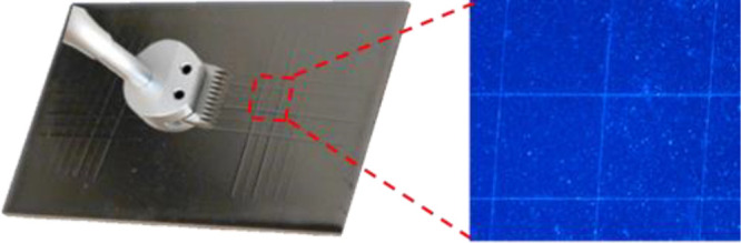
Adhesion test by cross-cut tester and tape stripping to clarify the superior adhesive properties of the coating with enlarged cross-cut grid by optical microscopy.
Conclusions
Infrared radiation efficiency and thermal conductivity are essential to the heat dissipation capacity of cooling coatings in the electrical encapsulation and energy fields. The fabrication of composites with high infrared radiation and thermal conductivity to improve the heat dissipation efficiency of coating films has become an urgent need. However, the infrared radiation efficiency has been severely reported in this field. Herein, we reported an in situ synthesized graphene/hexagonal boron nitride composite (Gr/h-BN) adopted in polydimethylsiloxane polymer to prepare highly efficiency infrared radiation and thermal conductive composites. The in situ combustion synthesis of Gr on the surface of h-BN particles guarantees a well-organized surface contact by the van der Waals force. The composite coating shows an infrared emissivity greater than 0.95 and a through-plane thermal conductivity up to 2.584 W·m–1·K–1, and in comparison to the reference fins, the temperature decreased from 175.6 to 153.9 °C (ΔT = 21.7 °C). The abrasion resistance of the composite coating on a pure Al substrate exhibits a superior adhesion property. Our results shed new light on the in situ combustion synthesis of heat dissipation coatings with noteworthy infrared radiation and thermal conductivity.
Glossary
Abbreviations
- Gr
graphene
- h-BN
hexagonal boron nitrite
- PDMS
polydimethylsiloxane
This work was supported by the Guangdong Basic and Applied Basic research Foundation (Grant No. 2020B1515120084), National Key R&D Program of China (Grant No. 2022YFE0201200), the National Natural Science Foundation of China (Grant No. 52071223), Key-Area Research and Development Program of Guangdong Province (Grant No. 2020B0101340002), and the Open Research Fund of Songshan Lake Materials Laboratory (Grant No. 2021SLABFN13).
The authors declare no competing financial interest.
References
- Brandis A.; Pelin D.; Matić T.; Topić D. Temperature Control Concept for Parallel IGBT Operation. Electronics 2021, 10 (4), 429. 10.3390/electronics10040429. [DOI] [Google Scholar]
- Cai J.; Ding L.; Wang J.; Jiang N. Impact of thermal interface material on power cycling lifetime of IGBT module. Microelectron Reliab 2021, 126, 114272. 10.1016/j.microrel.2021.114272. [DOI] [Google Scholar]
- Fan X.; Cui H.; Xu Y. IGBT Heat Dissipation Design and Optimization. J. Phys. Conf Ser. 2020, 1635 (1), 012024. 10.1088/1742-6596/1635/1/012024. [DOI] [Google Scholar]
- Lim D. J.; Pulko S. H. Characterisation of heat spreader materials for pulsed IGBT operation. IET Circuits Devices Syst, 2007, 1 (2), 126–136. 10.1049/iet-cds:20050227. [DOI] [Google Scholar]
- Niedernostheide F.-J.; Schulze H.-J.; Laska T.; Philippou A. Progress in IGBT development. IET Power Electronics 2018, 11 (4), 646–653. 10.1049/iet-pel.2017.0499. [DOI] [Google Scholar]
- Wang B.; Wang L.; Mu W.; Qin M.; Yang F.; Liu J.; Tomoyuki Y.; Tatsuhiko F. Thermal Performances and Annual Damages Comparison of MMC Using Reverse Conducting IGBT and Conventional IGBT Module. IEEE T Power Electr 2021, 36 (9), 9806–9825. 10.1109/TPEL.2021.3062620. [DOI] [Google Scholar]
- Li T.; Zhai Y.; He S.; Gan W.; Wei Z.; Heidarinejad M.; Dalgo D.; Mi R.; Zhao X.; Song J.; Dai J.; Chen C.; Aili A.; Vellore A.; Martini A.; Yang R.; Srebric J.; Yin X.; Hu L. A radiative cooling structural material. Science 2019, 364 (6442), 760. 10.1126/science.aau9101. [DOI] [PubMed] [Google Scholar]
- Liu C.; Wu W.; Wang Y.; Liu X.; Chen Q.; Xia S. Silver Nanoparticle-Enhanced Three-Dimensional Boron Nitride/Reduced Graphene Oxide Skeletons for Improving Thermal Conductivity of Polymer Composites. ACS Appl. Polym. 2021, 3 (7), 3334–3343. 10.1021/acsapm.1c00210. [DOI] [Google Scholar]
- Chen G.; Wang Y.; Zou Y.; Jia D.; Zhou Y. A fractal-patterned coating on titanium alloy for stable passive heat dissipation and robust superhydrophobicity. Chem. Eng. J. 2019, 374, 231–241. 10.1016/j.cej.2019.05.106. [DOI] [Google Scholar]
- Song G.; Kang R.; Guo L.; Ali Z.; Chen X.; Zhang Z.; Yan C.; Lin C. T.; Jiang N.; Yu J. Highly flexible few-layer Ti3C2 MXene/cellulose nanofiber heat-spreader films with enhanced thermal conductivity. New J. Chem. 2020, 44 (17), 7186–7193. 10.1039/D0NJ00672F. [DOI] [Google Scholar]
- Wang S.; Wang Y.; Zou Y.; Chen G.; Ouyang J.; Jia D.; Zhou Y. Biologically Inspired Scalable-Manufactured Dual-layer Coating with a Hierarchical Micropattern for Highly Efficient Passive Radiative Cooling and Robust Superhydrophobicity. ACS Appl. Mater. Interfaces 2021, 13 (18), 21888–21897. 10.1021/acsami.1c05651. [DOI] [PubMed] [Google Scholar]
- Shi N. N.; Tsai C. C.; Camino F.; Bernard G. D.; Yu N.; Wehner R. Keeping cool: Enhanced optical reflection and radiative heat dissipation in Saharan silver ants. Science 2015, 349 (6245), 298–301. 10.1126/science.aab3564. [DOI] [PubMed] [Google Scholar]
- Cui J.; Zhou S. Polyamine-functionalized perylene bisimide for dispersion of graphene in water with high effectiveness and little impact on electrical conductivity. J. Nanopart. Res. 2017, 19 (11), 357. 10.1007/s11051-017-4047-8. [DOI] [Google Scholar]
- Sun K.; Dong J.; Wang Z.; Wang Z.; Fan G.; Hou Q.; An L.; Dong M.; Fan R.; Guo Z. Tunable Negative Permittivity in Flexible Graphene/PDMS Metacomposites. J. Phys. Chem. C 2019, 123 (38), 23635–23642. 10.1021/acs.jpcc.9b06753. [DOI] [Google Scholar]
- Balandin A. A.; Ghosh S.; Bao W.; Calizo I.; Teweldebrhan D.; Miao F.; Lau C. N. Superior Thermal Conductivity of Single-Layer Graphene. Nano Lett. 2008, 8 (3), 902–907. 10.1021/nl0731872. [DOI] [PubMed] [Google Scholar]
- Du X.; Skachko I.; Barker A.; Andrei E. Y. Approaching ballistic transport in suspended graphene. Nat. Nanotechnol 2008, 3 (8), 491–495. 10.1038/nnano.2008.199. [DOI] [PubMed] [Google Scholar]
- Chaurasia A.; Verma A.; Parashar A.; Mulik R. S. Experimental and Computational Studies to Analyze the Effect of h-BN Nanosheets on Mechanical Behavior of h-BN/Polyethylene Nanocomposites. J. Phys. Chem. C 2019, 123 (32), 20059–20070. 10.1021/acs.jpcc.9b05965. [DOI] [Google Scholar]
- Maestre C.; Toury B.; Steyer P.; Garnier V.; Journet C. Hexagonal boron nitride: a review on selfstanding crystals synthesis towards 2D nanosheets. J. Phys. Mater. 2021, 4 (4), 044018. 10.1088/2515-7639/ac2b87. [DOI] [Google Scholar]
- Watanabe K.; Taniguchi T.; Kanda H. Direct-bandgap properties and evidence for ultraviolet lasing of hexagonal boron nitride single crystal. Nat. Mater. 2004, 3 (6), 404–409. 10.1038/nmat1134. [DOI] [PubMed] [Google Scholar]
- Wang J.; Ma F.; Liang W.; Sun M. Electrical properties and applications of graphene, hexagonal boron nitride (h-BN), and graphene/h-BN heterostructures. Mater. Today Phys. 2017, 2, 6–34. 10.1016/j.mtphys.2017.07.001. [DOI] [Google Scholar]
- da Rocha Martins J.; Chacham H. Disorder and Segregation in B-C-N Graphene-Type Layers and Nanotubes: Tuning the Band Gap. ACS Nano 2011, 5 (1), 385–393. 10.1021/nn101809j. [DOI] [PubMed] [Google Scholar]
- Luo W.; Zeng J.; Chen Y.; Dai W.; Yao Y.; Luo B.; Zhang F.; Wang T. Surface modification of h-BN and preparation of h-BN/PEI thermally conductive flexible films. Polym. Compos. 2022, 43 (6), 3846–3857. 10.1002/pc.26660. [DOI] [Google Scholar]
- Su Z.; Wang H.; Tian K.; Huang W.; Xiao C.; Guo Y.; He J.; Tian X. The combination of π-π interaction and covalent bonding can synergistically strengthen the flexible electrical insulating nanocomposites with well adhesive properties and thermal conductivity. Compos. Sci. Technol. 2018, 155, 1–10. 10.1016/j.compscitech.2017.09.018. [DOI] [Google Scholar]
- Zhang X.; Wu K.; Liu Y.; Yu B.; Zhang Q.; Chen F.; Fu Q. Preparation of highly thermally conductive but electrically insulating composites by constructing a segregated double network in polymer composites. Compos. Sci. Technol. 2019, 175, 135–142. 10.1016/j.compscitech.2019.03.017. [DOI] [Google Scholar]
- Bian B. A.; Yang J. J.; Han X. X.; Yuan P. P.; Ding Y. Q. Rectification in zigzag graphene/BN nanoribbon heterojunction. Mod. Phys. Lett. B 2018, 32 (32), 1850395. 10.1142/S0217984918503955. [DOI] [Google Scholar]
- Han Z.; Li M.; Li L.; Jiao F.; Wei Z.; Geng D.; Hu W. When graphene meets white graphene - recent advances in the construction of graphene and h-BN heterostructures. Nanoscale 2021, 13 (31), 13174–13194. 10.1039/D1NR03733A. [DOI] [PubMed] [Google Scholar]
- Patra L.; Mallick G.; Sachdeva G.; Shock C.; Pandey R. Orientation-dependent mechanical response of graphene/BN hybrid nanostructures. Nanotechnology 2021, 32 (23), 235703. 10.1088/1361-6528/abe671. [DOI] [PubMed] [Google Scholar]
- Song X.; Sun J.; Qi Y.; Gao T.; Zhang Y.; Liu Z. Graphene/h-BN Heterostructures: Recent Advances in Controllable Preparation and Functional Applications. Adv. Energy Mater. 2016, 6 (17), 1600541. 10.1002/aenm.201670102. [DOI] [Google Scholar]
- Ashhadi M.; Hadavi M. S.; Sarri Z. Electronic transport properties and first-principles study of graphene/h-BN and h-BN bilayers. Physica E Low Dimens 2017, 87, 312–316. 10.1016/j.physe.2016.11.012. [DOI] [Google Scholar]
- Leven I.; Maaravi T.; Azuri I.; Kronik L.; Hod O. Interlayer Potential for Graphene/h-BN Heterostructures. J. Chem. Theory Comput 2016, 12 (6), 2896–2905. 10.1021/acs.jctc.6b00147. [DOI] [PubMed] [Google Scholar]
- Srivastava S.; Pal P.; Sharma D. K.; Kumar S.; Senguttuvan T. D.; Gupta B. K. Ultrasensitive Boron-Nitrogen-Codoped CVD Graphene-Derived NO2 Gas Sensor. ACS Mater. Au 2022, 2 (3), 356–366. 10.1021/acsmaterialsau.2c00003. [DOI] [PMC free article] [PubMed] [Google Scholar]
- Xue J.; Sanchez-Yamagishi J.; Bulmash D.; Jacquod P.; Deshpande A.; Watanabe K.; Taniguchi T.; Jarillo-Herrero P.; LeRoy B. J. Scanning tunnelling microscopy and spectroscopy of ultra-flat graphene on hexagonal boron nitride. Nat. Mater. 2011, 10 (4), 282–285. 10.1038/nmat2968. [DOI] [PubMed] [Google Scholar]
- Wang T.; Li P.; Hu X.; Gao M.; Di Z.; Xue Z.; Zhang M. Wafer-scale fabrication of single-crystal graphene on Ge (110) substrate by optimized CH4/H2 ratio. Appl. Surf. Sci. 2020, 529, 147066. 10.1016/j.apsusc.2020.147066. [DOI] [Google Scholar]
- Lee W.; Kihm K. D.; Kim H. G.; Shin S.; Lee C.; Park J. S.; Cheon S.; Kwon O. M.; Lim G.; Lee W. In-Plane Thermal Conductivity of Polycrystalline Chemical Vapor Deposition Graphene with Controlled Grain Sizes. Nano Lett. 2017, 17 (4), 2361–2366. 10.1021/acs.nanolett.6b05269. [DOI] [PubMed] [Google Scholar]
- Ichikawa T.; Shimizu N.; Ishikawa K.; Hiramatsu M.; Hori M. Synthesis of isolated carbon nanowalls via high-voltage nanosecond pulses in conjunction with CH4/H2 plasma enhanced chemical vapor deposition. Carbon 2020, 161, 403–412. 10.1016/j.carbon.2020.01.064. [DOI] [Google Scholar]
- Dankert A.; Karpiak B.; Dash S. P. Hall sensors batch-fabricated on all-CVD h-BN/graphene/h-BN heterostructures. Sci. Rep. 2017, 7 (1), 15231. 10.1038/s41598-017-12277-8. [DOI] [PMC free article] [PubMed] [Google Scholar]
- Fan X.; Kim S.-W.; Tang J.; Huang X.; Lin Z.; Zhu L.; Li L.; Cho J.-H.; Zeng C. Spontaneous Folding Growth of Graphene on h-BN. Nano Lett. 2021, 21 (5), 2033–2039. 10.1021/acs.nanolett.0c04596. [DOI] [PubMed] [Google Scholar]
- Makino R.; Mizuno S.; Kageshima H.; Hibino H. Controlled CVD growth of lateral and vertical graphene/h-BN heterostructures. Appl. Phys. Express 2020, 13 (6), 065007. 10.35848/1882-0786/ab9169. [DOI] [Google Scholar]
- Kim S. M.; Hsu A.; Araujo P. T.; Lee Y.-H.; Palacios T.; Dresselhaus M.; Idrobo J.-C.; Kim K. K.; Kong J. Synthesis of Patched or Stacked Graphene and hBN Flakes: A Route to Hybrid Structure Discovery. Nano Lett. 2013, 13 (3), 933–941. 10.1021/nl303760m. [DOI] [PubMed] [Google Scholar]
- Li C.; Zhang X.; Wang K.; Sun X.; Liu G.; Li J.; Tian H.; Li J.; Ma Y. Scalable Self-Propagating High-Temperature Synthesis of Graphene for Supercapacitors with Superior Power Density and Cyclic Stability. Adv. Mater. 2017, 29 (7), 1604690. 10.1002/adma.201604690. [DOI] [PubMed] [Google Scholar]
- Choonee K.; Syms R. R. A.; Ahmad M. M.; Zou H. Post processing of microstructures by PDMS spray deposition. Sens. Actuator A Phys. 2009, 155 (2), 253–262. 10.1016/j.sna.2009.08.029. [DOI] [Google Scholar]
- He X.; Wang Y. Synergistic effects on the enhancement of thermal conductive properties of thermal greases. J. Appl. Polym. Sci. 2019, 136 (27), 47726. 10.1002/app.47726. [DOI] [Google Scholar]
- Kiran Raj M S. C. PDMS microfluidics: A mini review. J. Appl. Polym. Sci. 2020, 137 (27), 48958. 10.1002/app.48958. [DOI] [Google Scholar]
- Zhou L.; Song H.; Liang J.; Singer M.; Zhou M.; Stegenburgs E.; Zhang N.; Xu C.; Tien Ng.; Yu Z.; Gan Q. A polydimethylsiloxane-coated metal structure for all-day radiative cooling. Nat. Sustain. 2019, 2, 718–724. 10.1038/s41893-019-0348-5. [DOI] [Google Scholar]
- Ibáñez-Ibáñez P. F.; Montes Ruiz-Cabello F. J.; Cabrerizo-Vílchez M. A.; Rodríguez-Valverde M. A. Ice adhesion of PDMS surfaces with balanced elastic and water-repellent properties. J. Colloid Interface Sci. 2022, 608, 792–799. 10.1016/j.jcis.2021.10.005. [DOI] [PubMed] [Google Scholar]
- Mason R.; Koberstein J. T. Adhesion of PDMS Elastomers to Functional Substrates. J. Adhesion 2005, 81 (7), 765–789. 10.1080/00218460500188838. [DOI] [Google Scholar]
- Deshpande T. D.; Singh Y. R. G.; Patil S.; Joshi Y. M.; Sharma A. Adhesion strength and viscoelastic properties of polydimethylsiloxane (PDMS) based elastomeric nanocomposites with embedded electrospun nanofibers. Soft Matter 2019, 15 (28), 5739–5747. 10.1039/C9SM00533A. [DOI] [PubMed] [Google Scholar]
- Jang H.; Kang I.-S.; Lee Y.; Cha Y. J.; Yoon D. K.; Ahn C. W.; Lee W. Direct transfer of multilayer graphene grown on a rough metal surface using PDMS adhesion engineering. Nanotechnology 2016, 27 (36), 365705. 10.1088/0957-4484/27/36/365705. [DOI] [PubMed] [Google Scholar]
- Pan Z.; Peng R.; Tang J.; Chen L.; Cheng F.; Zhao B. Surface-Segregation-Induced Nanopapillae on FDTS-Blended PDMS Film and Implications in Wettability, Adhesion, and Friction Behaviors. ACS Appl. Mater. Interfaces 2018, 10 (8), 7476–7486. 10.1021/acsami.7b19034. [DOI] [PubMed] [Google Scholar]
- Zheng F.; Yang Y.; Chen Q. High lithium anodic performance of highly nitrogen-doped porous carbon prepared from a metal-organic framework. Nat. Commun. 2014, 5 (1), 5261. 10.1038/ncomms6261. [DOI] [PubMed] [Google Scholar]
- Kumar A.; Malik G.; Sharma S.; Chandra R.; Mulik R. S. Precursors controlled morphologies of nanocrystalline h-BN and its growth mechanism. Ceram. Int. 2021, 47 (21), 30985–30992. 10.1016/j.ceramint.2021.07.256. [DOI] [Google Scholar]
- Ferrari A. C.; Meyer J. C.; Scardaci V.; Casiraghi C.; Lazzeri M.; Mauri F.; Piscanec S.; Jiang D.; Novoselov K. S.; Roth S.; Geim A. K. Raman Spectrum of Graphene and Graphene Layers. Phys. Rev. Lett. 2006, 97 (18), 187401. 10.1103/PhysRevLett.97.187401. [DOI] [PubMed] [Google Scholar]
- Li Q.; Tian X.; Wu N.; Li Y.; Pan T.; Zhang B.; Duan Y.; Wang S.; Li Y. Enhanced thermal conductivity and isotropy of polymer composites by fabricating 3D network structure from carbon-based materials. J. Appl. Polym. Sci. 2021, 138, 49781. 10.1002/app.49781. [DOI] [Google Scholar]