Abstract
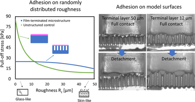
Adhesives for interaction with human skin and tissues are needed for multiple applications. Micropatterned dry adhesives are potential candidates, allowing for a conformal contact and glue-free adhesion based on van der Waals interactions. In this study, we investigate the superior adhesion of film-terminated fibrillar microstructures (fibril diameter, 60 μm; aspect ratio, 3) in contact with surfaces of skin-like roughness (Rz 50 μm). Adhesion decays only moderately with increasing roughness, in contrast to unstructured samples. Sinusoidal model surfaces adhere when their wavelengths exceed about four fibril diameters. The film-terminated microstructure exhibits a saturation of the compressive force during application, implying a pressure safety regime protecting delicate counter surfaces. Applications of this novel adhesive concept are foreseen in the fields of wearable electronics and wound dressing.
Keywords: skin adhesives, bioinspired structures, soft layer, dry adhesion, roughness
1. Introduction
Skin-attachable adhesives are experiencing rising demands in healthcare, where potential applications range from flexible and wearable electronics for monitoring and diagnosing biological signals1−3 to therapeutic devices and wound dressings.4,5 Biological surfaces and tissues are challenging counter surfaces to stick to, as surface roughness is one key factor for reduced adhesion.1 This is primarily due to the difficulty of achieving fully conformal contact, which decreases the real contact area and causes heterogeneous stress distributions at the interface.6 Roughness requires high local deformations and hence counteracts the short-range adhesive molecular forces.7,8 As a consequence, new adhesives for reliable yet delicate interaction with skin-like surfaces are urgently required.
The efficiency and versatility of several attachment systems in nature, e.g., in geckos, beetles, spiders, or snails, have been a source of inspiration to material scientists and engineers: in many cases, their outstanding locomotion and clinging ability, to various smooth and rough surfaces, are due to patterned micro- and nanostructures on their contact organs. The bioinspired microfibrillar patterns derived from these examples have been widely studied in the past few years.9−11 More recently, they have proven to be potential candidates as dry and glue-free adhesives to skin. Current solutions for skin adhesives offer too strong adhesion causing damage while being removed,12,13 in addition to being of single use and leaving residues that can cause skin irritation and allergies. Therefore, a reliable adhesive with sensitive detachment is needed.14,15
Dry adhesion is mediated by conformal contact, enhanced by a low effective elastic modulus, and Van der Waals (vdW) interactions, both of which contribute to useful adhesion even to rough surfaces.16−19 For skin applications, a film-terminated design was proposed, which modifies the microfibril array by adding a continuous terminal layer made of softer material. This modified microstructure has shown enhanced adhesion by modulating the interfacial stresses and generating a crack trapping mechanism; the result is an interesting synergy between the subsurface microstructure and the soft, thin terminal layer.19−22 The added layer also performs auxiliary functions: in wound dressings, it can aid in the closure of the wound; and in the treatment of eardrum perforations, it closes the fissure in the membrane, which is important to block pathogens from entering the middle ear during the treatment.5,23
As the largest organ in humans, the skin presents an especially complex topography, which can vary over several orders of magnitude. The detailed structure depends on many factors, such as body location, age, and humidity.24−26 Explicit studies that take into account the roughness of skin when optimizing skin adhesives have rarely been published in the literature.
In this paper, we aim to investigate the adhesion mechanism of novel film-terminated microstructures designed to adhere specifically to rough skin without the need for chemical glues, thus not leaving residues on the surface or causing adverse reactions. We conduct a systematic investigation of such microstructures, consisting of two biomedical silicones, on a series of surfaces with random and single-wavelength roughness. Adhesion is analyzed in comparison to unstructured films as control samples. We evaluate experimentally and numerically the effect of the terminal layer thickness and the role of the fibrillar microstructure on the adhesion performance. In this way, we provide a scientific base for this new class of micropatterned skin adhesives.
2. Experimental Section
2.1. Fabrication of Film-Terminated and Control Samples
Film-terminated microstructures were fabricated, and the respective unstructured samples with the terminal layer were used as a control to investigate the effect of the subsurface microstructure on adhesion.
Arrays with fibrils of nominal height of 180 μm and diameter of 60 μm (aspect ratio 3) were fabricated by replica molding. The fibrils were arranged hexagonally with center-to-center distances of 120 μm (surface density approximately 23%). A silicon master template (Institute of Semiconductors and Microsystems, TU Dresden, Germany) was used to prepare the negative silicone mold (Elastosil M4601 A/B silicone, Wacker Chemie AG, Munich, Germany). The prepolymer was mixed (ratio 9:1) and poured on the master template. The silicone was then cured in an oven at 75 °C for 3 h. The silicone mold was treated by air plasma (Atto low pressure plasma system, Electronic Diener, Ebhausen, Germany) for 3 min and then coated with tridecafluoro-1,1,2,2-tetrahydrooctyl-trichlorosilane (AB111444, ABCR, Karlsruhe, Germany) through vapor deposition at 3 mbar for 45 min. The microfibrillar array was made from the biomedical-grade elastomer MDX4-4210 (Dow Silicones, Midland, Michigan). The prepolymer was mixed in a ratio of 10:1, poured on the Elastosil mold, and degassed for 5 min. The mold was then spun at 3000 rpm for 2 min (Spincoater Laurel l WS 650 MZ-23NPPB, North Wales, Pennsylvania) and then placed on a glass substrate, which was previously plasma-treated and coated with MDX4 silicone (3000 rpm for 2 min). The whole set was placed in an oven at 95 °C for 1 h. Finally, the mold and the glass were gently demolded. For the unstructured control samples, a foil of the MDX4-4210 was prepared by spin coating at 500 rpm for 2 min to achieve a thickness comparable to the sum of the backing layer and fibril height for the fibrillar microstructure.
In the second step, the microfibrillar array, or the respective flat film, was film-terminated. Accordingly, a soft skin adhesive film, SSA MG7-1010 (Dow Silicones, Midland, Michigan), was used. Previous reports use a softer material by changing the mixing ratio of the “stiffer” silicone.27,28 However, this approach makes the product unsuitable for medical applications, as the manufacturer does not predict the reactivity and curing conditions, being, therefore, not medically certified. The SSA was coated on a release foil (Siliconature, SILFLU S 75 M 1R88002 clear) at 800, 2000, and 6000 rpm. The SSA layer was cured at 95 °C for 1 h. To combine the microfibrillar array with the SSA layer, fibril tips were dipped in an uncured MDX4-4210 layer (spun on a glass substrate at 400 rpm) and placed on the cured SSA film. The unstructured control sample was terminated using the same method, dipping the film in an uncured MDX4 layer before placing it on the cured SSA layer. Upon curing in an oven at 95 °C for 1 h, the final specimen was peeled from the release foil. The fibril height increased from 180 to 200 μm (and the aspect ratio from 3 to 3.3) due to the fabrication described above. Considering biomedical applications, only certified medical products MDX4-4210 and MG7-1010 were used.
Specimens were characterized using an optical microscope (Eclipse LV100ND, Nikon, Tokyo, Japan) and a scanning electron microscope (FEI Quanta 400 ESEM, Thermo Fisher). The specimens were analyzed under low vacuum at 100 Pa and 10 kV voltage for the latter.
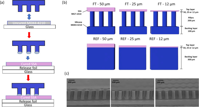
Figure 1a presents a summary of the fabrication process of the film-terminated microstructure. The fibrils are fabricated by replica molding and yield precise copies by a relatively inexpensive method. Unlike simple porosity, the fibrils offer an additional advantage of a controlled, periodic structure suitable for subsequent integration of other systems. The cross sections of the film-terminated and respective control samples are illustrated in Figure 1b. The MDX4-4210 fibrillar array (in blue) consisted of a 100 μm backing layer and fibril arrays of 200 μm height and 60 μm diameter, and the SSA MG7-1010 terminating layer (in pink) varied in thickness of 12, 25, and 50 μm. The chosen materials are medically certified for wound dressings and implantable devices, widening the possibility of application of these microstructured adhesives for different purposes, including wound dressings. For brevity, we denote the samples according to their terminal layer thickness, for instance, FT—12 μm for the film-terminated microstructure with a 12 μm thick terminal layer. The respective unstructured reference samples were fabricated with the MDX4-4210 backing layer of 300 μm and the terminal layer equivalent to the microstructures (12, 25, or 50 μm thickness). In addition, microfibrils without thin film as the terminal layer were also used for control measurements. Scanning electron microscopy (SEM) images of different samples are presented from 45° tilt side view (Figure 1c). We observe that the thinnest film is slightly deformed due to stress relaxation.
Figure 1.
Film-terminated microfibrillar samples. (a) Representation of the film-terminated microstructure fabrication process by integrating an SSA film with a microfibril sample. The tips of the fibrils are dipped in an uncured film and then placed on a cured SSA layer. (b) Schematic cross section of a soft skin adhesive (SSA) film (pink) terminating a silicone microfibrillar array of MDX4-4210 (blue) and of the unstructured control samples. The terminating film has various thicknesses of 12, 25, and 50 μm. (c) Representative scanning electron micrographs of the different samples.
2.2. Rheometry
Frequency-dependent storage and loss moduli (G′, G″) and the damping factor tan δ = G″/G′ of the polymers were determined using a rheometer (Physica MCR-300, Anton Paar, Graz, Austria) equipped with a cone/plate setup (diameter, 25 mm; gap height, 0.054 mm). The prepolymer mixture of components A and B (in a mixing ratio of 10:1 for MDX4-4210 and 1:1 for the SSA) was placed on the device. The polymer was cured between the plates at 90 °C for 30 min. Upon cooling to 25 °C, a frequency sweep measurement from 0.01 to 100 Hz at a constant amplitude of 0.1% was carried out.
The Young’s modulus, E, for both materials was calculated from the measured storage modulus in shear, G, considering E = 2G (1 + ν), with ν = 0.5. The elastic modulus values obtained were EMDX4-4210 = 1.01 MPa and ESSA = 0.102 MPa. Overall, the terminating film was made from softer silicone than the microfibrillar array.
2.3. Adhesion Measurements
Probe tack tests, in which a flat probe is retracted from the adhesive in the perpendicular direction, were performed using a custom-built adhesion testing device.16,29 Specimens and the counter surface were approached at a rate of 30 μm/s until a predetermined compressive preload or displacement was reached. Contact was held for 1 s, followed by retraction at a rate of 10 μm/s. Measurements were performed at three different positions on each surface. Mean values and standard deviation (error bars) were reported. Counter surfaces were always smaller than specimens; therefore, stresses were calculated by dividing force values by the area of the counter surface. All surfaces were made from epoxy (Résine Epoxy R123, Soloplast-Vosschemie, Fontail-Cornillon, France), as described in previous reports,30,31 to keep surface chemistry constant. Epoxy replicas were made from smooth and frosted glass slides (Marienfeld, Lauda Königshofen, Germany) and the front and back sides of Vitro-Skin foil (IMS inc., Portland, ME). Vitro-Skin foil was chosen as it mimics the topography of the human skin.32,33
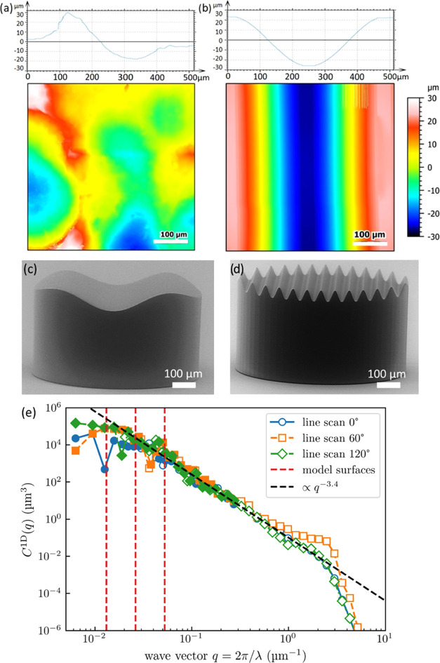
A contour map of the skin-like surface and a cross-sectional profile are depicted in Figure 2a. It presents arithmetic roughness (Ra) of 9.48 μm and a peak-to-valley distance of ∼50 μm in accordance with the statistical value Rz = 50 μm. Adhesion to such high roughness has not yet been described in the literature; for the film-terminated microstructure, adhesion has only been reported in the literature against the roughness of maximal Ra 2.3 μm.20 A sinusoidal model surface of wavelength 480 μm is depicted in Figure 2b. The surfaces were imaged using a confocal microscope (MarSurf CM explorer, 50× objective, Mahr, Göttingen, Germany). At a constant peak-to-valley distance of 50 μm, corresponding to the skin-like surface, the following different wavelengths were chosen: λ = 480, 240, 120, and 60 μm. The model surfaces were fabricated using two-photon lithography (Photonic Professional GT2, Nanoscribe, Eggenstein–Leopoldshafen, Germany). SEM images of the printed sinusoidal model surfaces are presented in Figure 2c,d.
Figure 2.
Surface profile and topography of counter surfaces. (a) Scan of skin-like rough surface, in comparison to (b) sinusoidal model surface with 480 μm wavelength. (c) and (d) SEM micrographs of the printed surfaces with the sinusoidal model surface of wavelengths 480 μm and 60 μm, respectively. (e) Power spectral density (PSD) of the Vitro-Skin surface, determined from line scans along different surface directions. Solid markers indicate reliable data, while empty markers indicate unreliable data as limited by the tip radius.34 The isotropic one-dimensional PSD (C1D) is defined as given in ref (35). The dashed vertical red lines represent the wavelengths of the model surfaces.
To rationalize the choice of model surface wavelengths, we analyzed the Vitro-Skin topography using a profilometer (SURFCOM 1500SDS, ACCTee Software, Ostfildern, Deutschland) with a tip of 2 μm diameter and a measuring speed of 0.3 mm/s and characterized by the surface topography analyzer.35 The corresponding power spectral density (PSD) is shown in Figure 2e, where the reliability of data points was explicitly determined from the curvature of the profilometer’s tip radius.34 Since line scans along different directions look very similar, the surface can be considered isotropic. Assuming a self-affine fractal topography, the slope of the curve would suggest a Hurst exponent of approximately 1.2, outside the range of [0,1], indicating that the surface is not in fact fractal. Recently, Gujrati et al. connected an exponent of −4 in the PSD to macroscopic patterns in surface coatings.36 The exponent −3.4 could indicate the presence of similar features overlapping with a self-affine power law. Regardless of the exact interpretation, a decrease with a large exponent equivalent to H > 0.5 still indicates that long wavelength features within this range have a much more significant influence on contact mechanics than short wavelength features.37 The sinusoidal model surfaces are chosen close to the roll-off point on the left end of the spectrum, where the graph transitions from the power law behavior to being almost constant. This range is decisive for the elastic energy to contact nominally flat surfaces, as we use in normal tack tests. This condition for the choice of the model surface is explained in more detail in Section 4.3.
2.4. Finite-Element Analysis (FEA)
Finite-element analyses (FEA) were carried out using Abaqus (Dassault Systems, Simulia Corporation, RI).38 The two-dimensional model consisted of an elastic film-terminated sample meshed with a CPS4R element and a rigid sinusoidal surface meshed with R2D2 elements. The dimensions of the model remained the same as in the experiments (all dimensions are normalized by the fibril diameter of 60 μm), i.e., fibril height = 3, center-to-center distance = 2, terminal layer thicknesses = 1/5 or 5/6, sinusoidal amplitude = 5/6, and wavelengths = 4 and 8, separately. Both fibrils and the terminating film were modeled as incompressible neo-Hookean elastic solids with Young’s moduli of 1.1 and 0.102 MPa, respectively. Two relative configurations of the fibrils and sinusoidal surface were considered: fibrils were either centered on the maxima or shifted by 60 μm. The interaction property between the film-terminated sample and the wavy surface was defined as “hard contact” for normal contact and “friction with penalty” for tangential contact. To avoid slippage after the contact, the penalty coefficient μ was set to 0.5, corresponding to the friction coefficient in the Coulomb friction law, τfric = μP, where P is the normal contact pressure between the contacting surfaces. The step “dynamic, implicit” was used to calculate the actual deformation by uniaxial loading, during which only the vertical displacement of the top surface of the backing layer was set while other translational degrees of freedom were fixed to mimic the constraint of the backing layer in the experimental sample.
3. Results
3.1. Adhesion to Smooth Counter Surfaces
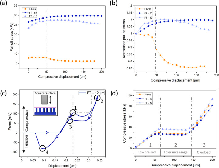
Figure 3 shows a summary of adhesion results of the FT—12 μm, FT—50 μm, and fibril samples without the terminal layer against a smooth flat epoxy surface. In Figure 3a, the adhesion of the FT samples ranged between 24 and 30 kPa, which was 3–5 times larger than samples without a terminating layer. The FT—50 μm sample consistently led to a higher pull-off stress than that of the FT—12 μm sample, which could be attributed to the vastly reduced influence of the much stiffer fibrils in comparison to the terminal layer.
Figure 3.
Results of adhesion tests against a smooth epoxy surface. (a) Pull-off stress and (b) normalized pull-off stress (by the pull-off stress at zero compression) as a function of maximum compressive displacement for film-terminated (FT) microfibrils (blue) in comparison to nonterminated fibrillar arrays (orange). The dashed-dotted line indicates the onset of fibril buckling. (c) Force vs displacement display of measurement of the film-terminated sample with 12 μm thick film and a schematic representation of the measurement principle. Points highlight fibril buckling (1), maximum compression (2), unbuckling of fibrils (3), and maximum pull-off force (4). (d) Compressive stress as a function of compressive displacement. Dashed-dotted lines mark three regimes: (1) low preload, (2) compression-tolerant regime, and (3) overload regime, and correspond to the lines in panel (c).
Compressive load is an important factor for adhesion to achieve optimal contact with the counter surface.39 We observe that the microfibrils without terminating film exhibited a substantial reduction in adhesion at about 50 μm maximum compressive displacement (dashed-dotted line). This reduction is even clearer in Figure 3b, where the pull-off stress was normalized by its value at zero compression. The initial buckling position (point 1) is shown in an example of force–displacement curve on the FT—12 μm sample in Figure 3c; located at a compression displacement at 50 μm, it corresponds to the position with the large drop in adhesion in Figure 3b. After buckling, the decrease of the compressive force is attributed to the postbuckling instability.40,41 When the deformed fibrils topple over and contact the backing layer, the compressive load increases again until the maximum compressive load is reached (point 2). Point 3 in the graph marks the elastic recovery of the buckled fibrils. The hysteresis between points 1 and 3 can most likely be attributed to viscoelastic properties of the materials. Finally, detachment occurred, and the pull-off force was obtained from the maximum in the tensile force (point 4).
The evaluation of the compressive load in terms of the maximum compressive displacement is depicted in Figure 3d. Three regimes can be identified: a low preload, a force tolerant, and an overload regime. In the first regime, the pull-off force increases linearly with increasing displacement; the force saturates in regime 2, where the compressive force is insensitive to the displacement; and in regime 3, the compressive force increases linearly again with a higher slope, indicating densification of the fully compressed fibrils.
The experimental setup, as well as the detachment process of the film-terminated structure from the smooth epoxy surface, can be seen in Figure 4. The large circular margin in Figure 4b illustrates the surface position and darker regions enclosed by the dashed lines represent the edge of the contact area. The crack initiates from the edge of the counter surface and moves inward for both samples. The crack path (dashed lines) is more tortuous for the thinner backing layer (FT—12 μm) and reflects the underlying fibrillar structure.
Figure 4.
Contact surface imaging during detachment from the smooth surface. (a) Schematic representation of the experimental setup, in which a prism for observation of the contact surface is mounted on the load cell. (b) Screenshots of the contact surface of FT—12 (above) and FT—50 (below) against a smooth surface during detachment (left to right). The detachment front is highlighted by the yellow dotted line.
3.2. Adhesion Results to Surfaces with Random Roughness
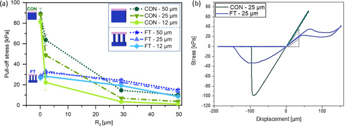
Next, adhesion tests on randomly rough surfaces were conducted to investigate the advantage of the terminal layer design. Figure 5a shows the pull-off stress in terms of the surface roughness Rz (mean peak-to valley distance) ranging from 0.1 to 50 μm. The pull-off stresses for the FT samples with different terminal layer thicknesses are all located between 25 and 30 kPa for the smoothest surface (Rz = 0.1 μm). Under the same measurement conditions, the effect of the terminal layer thickness is not distinguishable. The unstructured control samples, on the other hand, present pull-off stresses between 80 and 90 kPa, up to 3 times higher than the microstructure. In Figure 5b, examples of stress–displacement curves for the microstructured FT—25 sample and the respective unstructured control are presented.
Figure 5.
Adhesion against rough surfaces. (a) Pull-off stress of the film-terminated microstructure and control samples, as a function of roughness Rz of the counter surface, from smooth (Rz = 0. 1 μm) to skin-like roughness (Rz = 50 μm) at a preload of 10 kPa and a hold time of 1 s. (b) Example of stress–displacement curve of FT—25 μm and of reference CON—25 μm, subjected to a larger compressive preload.
As the roughness Rz was increased to 1.1 μm, we observed a slight increase of pull-off stress for the microstructured samples, more pronounced for the samples FT—50 and FT—25 (27 and 28 kPa to 32 and 33 kPa, respectively) than for FT—12 (26–28 kPa). The control samples, on the other hand, showed a reduction in pull-off stress (88–64 kPa for FT—50 and 81–22 kPa for FT—12).
Further increase in surface roughness led to a decline in pull-off stress for all samples. The decay for the control samples was, however, much more substantial: for roughness Rz = 50 μm (skin-like), CON—50 had the adhesion reduced by 88%, going from 88 kPa to around 10 kPa, and CON—12 had a reduction by 98%, reaching 1.1 kPa at high roughness. Microstructured samples, on the other hand, had a less pronounced decay; FT—50 went to 15 kPa, losing around 43% of the adhesion performance in comparison to a smooth counter surface, and FT—12 went to around 8.5 kPa, a reduction to 32% of its initial value.
3.3. Adhesion Results to Sinusoidal Model Surfaces
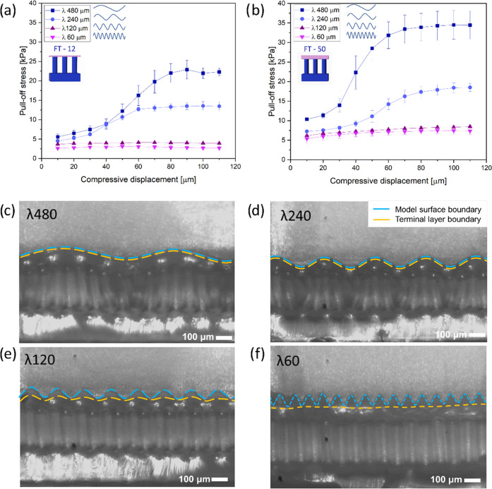
Pull-off stresses as a function of compressive displacement for FT—12 μm and FT—50 μm against the different sinusoidal model surfaces are presented in Figure 6a,b. As before, the sample with the thicker terminal layer (FT—50 μm) showed higher adhesion values. The wavelength of the counter surface modulated the adhesive behavior in the following ways.
Figure 6.
Adhesion of film-terminated microstructures on sinusoidal model surfaces. Pull-off stress vs compressive displacement for the sample with the terminal layer: (a) 12 μm and (b) 50 μm for the surfaces with different wavelengths. Snapshots show side view of FT—50 against surfaces with wavelengths: (c) 480 μm, (d) 240 μm, (e) 120, and (f) 60 μm in the compressed state. Scale bar is 100 μm. Blue dashed lines mark the model surface boundary, and yellow dashed lines indicate the microstructure’s terminal layer boundary.
For wavelengths of 60 and 120 μm, i.e., close to the fibril diameter, the pull-off stress was almost insignificant (around 4 kPa for FT—12 μm and 7.5 kPa for FT—50 μm) and increased only slightly with increasing compressive displacement.
For the longer wavelengths of 240 and 480 μm, adhesion was generally higher and increased in a more pronounced way with a compressive displacement between 30 and 70 μm. The final plateau values were 13 and 25 kPa for FT—12 and 17 and 35 kPa for FT—50.
The transition from low to high adhesion for the long-wavelength surfaces occurred at a compressive displacement of about 50 μm, which corresponds to the amplitude of the sinusoidal surface shape.
In Figure 6c–f, we present in-situ lateral views of the sample FT—50 μm in a compressed state against all of the counter surfaces. A physical impediment to full contact is observed for the counter surfaces with wavelengths 60 and 120 μm, where contact was achievable only near the surface peaks, even at high compression. By contrast, the terminal layer of the microstructure eventually achieved “full” contact with the counter surfaces of wavelengths 240 and 480 μm. The transition between the two different kinds of adhesion behavior seems to occur at the following empirical condition
| 1 |
where D is the fibril diameter and λ is the wavelength. For λ < 4D, the pull-off stress is low and insensitive to the compressive preload as full contact with the counter surface is always prevented. On the other hand, for λ ≥ 4D, the microstructure could deform almost conformally to the rough surface and the pull-off stress increased with the preload. The performance of the adhesive in the case λ ≥ 4D was further investigated.
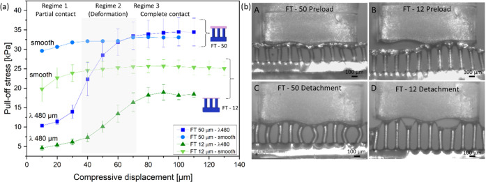
Figure 7a presents a comparison of adhesion results for FT—12 and FT—50 samples against the smooth surface and the model surface of wavelength 480 μm. For the smooth surface, the slight increase of pull-off stress, mostly at the initial compressive displacement, can be explained by full contact formation and, possibly, by a contribution of the material’s viscoelasticity.42,43 For the sinusoidal model surface, three regimes can be distinguished: In regime 1, the sample and counter surface have low contact; next, in regime 2, the fibrils undergo bending, which allows them to form progressively more contact with inclined areas of the counter surface and creates higher adhesion; finally, in regime 3, the sample reaches close-to-full contact and adhesion enters a plateau. For sample FT—12, the plateau stress values amount to approximately 70% of the values obtained for the smooth surface. Interestingly, the FT—50 sample reaches, within the error margin, similar adhesion as on the smooth surface.
Figure 7.
Adhesion of microstructures on model surface 480 μm in comparison to the smooth surface. (a) Pull-off stress as a function of compressive displacement for FT—50 and FT—12 against the smooth surface and model surface of wavelength 480 μm. (b) Side view of single row FT—50 in full contact (A) and detachment (B) and FT—12 in full contact (C) and detachment (D) against the 480 μm wave model. Scale bar is 100 μm.
In Figure 7b, side views of detachment from the model surface with wavelength 480 μm are presented for a single row of fibrils for better visualization. The ability of the fibrillar microstructure to conform to the wavy counter surface is well illustrated and will be discussed below.
3.4. Finite-Element Simulation Results
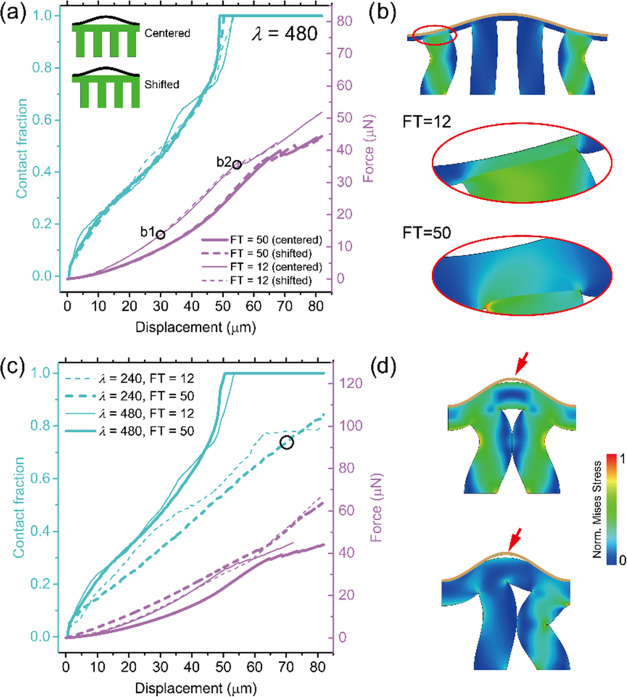
To obtain better quantitative insights into the contact behavior, information not accessible by the experimental setup, we analyzed the numerical results of our finite-element simulations for samples FT—12 and FT—50 μm in contact with the λ = 480 μm surface. Contact fraction (i.e., percentage contact area of the total surface) and compressive force were calculated with increasing compressive displacement for two different alignments: in one case, a fibril was centered on a wave valley and, in the other, the space between was centered, as indicated in the insets in Figure 8a. The force results overlapped for displacements smaller than 30 μm and subsequently diverged somewhat; the shifted arrangement produced slightly higher force values, but the overall fibril alignment did not strongly affect contact fractions. Full contact was achieved for compressive displacement larger than 55 μm. Figure 8b presents a snapshot of FT—12 samples in full-contact configuration, as well as the terminal layer in both cases in the highlighted region. The FT—12 fibrils underwent severe bending in accordance with the experimental observations in Figure 7.
Figure 8.
Simulation of compressive force and contact fraction for model surface 480 μm (a and b) and surface 240 μm (c and d). (a) Relations of contact fraction and compressive force vs compressive displacement for FT—12 and FT—50 samples with λ = 480 μm, in centered and shifted alignment. (b) Snapshots of deformation processes of FT—12, with the highlighted region of the terminal layer of both samples in positions marked “b1” and “b2” in panel (a). (c) Relationship between the contact fraction and compressive force vs compressive displacement for surface λ = 240 and 480 μm separately. (d) Snapshots at a contact fraction of about 70% and a displacement of about 70 μm of the critical deformation moment when the neighboring fibrils touch each other under centered and shifted arrangements when λ = 240 μm.
Subsequently, we compared the simulation results for the cases λ = 240 and 480 μm (Figure 8c). Here, all of the curves represent the average results of the centered and shifted alignments. While, in most cases, the contact area increased monotonically until full contact was reached, significantly higher forces were required for the 240 μm surface. A new event was observed for the λ = 240 μm surface: the contact fraction of the FT—12 sample leveled off at 77% (at a compressive displacement of 65 μm). The snapshots in Figure 8d explain this inability to achieve full contact: at a critical displacement of about 70 μm, severely bent neighboring fibrils start to impinge, which prevents further contact from forming. Although the optical observation in Figure 7b (λ = 240 μm) seems to indicate full contact, the numerical result in Figure 8c reveals that the system may not be able to reach this state in the model topography. This may, to some extent, explain the earlier detachment and lower pull-off stress for λ = 240 μm compared to λ = 480 μm.
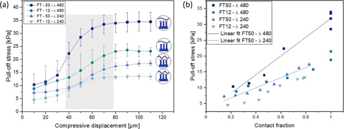
Figure 9a shows the pull-off stress for FT—50 and FT—12 on the counter surfaces of λ = 480 and 240 μm. Similarly, for all cases, the pull-off stress increases with increasing displacement and saturates to a plateau value. Although camera images (Figure 6c,d) suggest that the microstructures have contact with both surfaces, 240 and 480 μm, numerical simulations showed that, in fact, the surface 240 μm only reaches 80% of its full contact surface when the maximum displacement is 80 μm. This could possibly cause the lower pull-off stress values when detaching from the 240 μm surface for both FT—12 and FT—50 samples.
Figure 9.
Adhesion on model surfaces 480 and 240 μm. (a) Pull-off stress for FT—50 and FT—12 as a function of maximum displacement for the waves of λ = 480 and 240 μm. A similar trend is observed for the wave 240 μm, in comparison to the larger one, described in detail in the main text. (b) Measured pull-off stress as a function of contact fraction during compression, obtained from the simulations. Linear fit is indicated for FT—50 for both surfaces 480 and 240 μm.
The correlations between the contact fraction and pull-off stress are plotted with the help of both experimental and simulation results (Figure 9b), in which the pull-off stress is obtained from experiments, the contact fraction is only acquired by simulations, and the compressive displacement is the bridge. The pull-off stress goes up linearly with the increase of contact fraction in each case. For FT—12 samples, the pull-off stress at the same contact fraction is not significantly influenced by the wavelength λ. On the contrary, FT—50 samples show a wavelength λ dependence: larger λ leads to a higher pull-off stress.
4. Discussion
Envisioning a self-adhesive microstructure for biomedical applications, especially on skin, we propose, in this investigation, a fibrillar array terminated by a soft, thin film, using biomedically certified materials. Roughness of the counter surface is a well-known obstacle for adhesion because it increases the elastic strain energy penalty in the adhesive, attempting to conform to the rough topography. As skin exhibits roughness to various degrees, this paper explores the adhesion of novel skin adhesives to counter surfaces of various roughnesses. The counter surfaces investigated exhibited randomly distributed irregularities, from glass-like to skin-like roughness, complemented by sinusoidal model roughness. The essential observations will now be discussed in turn.
4.1. Comparison of Smooth vs Rough Counter Surfaces: The Benefit of Fibrillar Microstructures
The first result of our work is the observation that the microstructure did not always lead to improved adhesion: in contact with smooth counter surfaces, unstructured control samples were about three times more adhesive than fibrillar microstructures (Figure 5a). As the unstructured films can adapt well to a smooth counter surface, the micropatterning of the film-terminated microstructure does not add any advantage to the adhesive behavior; on the contrary, it may be argued that the reduced areal density of the fibrils (about 22.5% of the nominal area) will reduce the effective contact stiffness by a similar factor. Such a difference was observed in Figure 5b, where the slope of the stress–displacement data during compression differed by a factor of approximately 2. Additional contributions may be due to the fibril-induced inhomogeneous stress fields at the interface, which could favor the initiation and propagation of interfacial cracks.
The situation changes considerably when a counter surface with roughness is considered. Here, the higher compliance of the micropatterned sample with graded modulus will allow much better conformity to the peaks and valleys of the counter surface; this mechanism is clearly illustrated in the side view pictures of Figure 6b for the case of a single-wavelength model surface. It is noteworthy that, for a surface wavelength of 480 μm, the “plateau” value of the thicker terminal layer was about twice that of the thinner layer (Figure 6a). In the full contact state (Figure 7A,C), the sample with the thinner terminal layer, FT—12, exhibits more pronounced fibril bending than sample FT—50. This suggests that the thicker terminal layer contributes more elastic accommodation and requires less fibril bending. As presented in Figure 7 b (B,D), the detachment initiates preferentially in the valley rather than along the surface edges as previously described for the smooth surface. Empirically, it was found that the wavelength must exceed four fibril diameters (eq 1).
4.2. Compressive Behavior of Microstructures: The Benefit of Overload Protection
The behavior of a skin adhesive during attachment is also decisive for its applicability in a biomedical context. The fibrillar microstructures presented here exhibited a beneficial characteristic (Figure 3d): during compression, a plateau regime was encountered (marked “regime 2”), in which the compressive stress acting on the counter surface was insensitive to compressive displacement. Mechanistically, the force plateau is linked to the buckling instability of the microfibrillar array (Figure 3c,d). Considering the Young’s modulus, E, of 1.1 MPa, n = 513 microfibrils, a fibril radius, R, of 30 μm, and the fibril height, h, of 200 μm, the critical buckling load can be estimated by Euler buckling theory Pb = αnEπ3R4/4h2, where α = 4 for clamping of both ends.40,41 Thus, Pb = 0.177 N, and the buckling stress for the surface of 6.2 mm2 is 28.5 kPa, which is in the same range as obtained experimentally.
This buckling event creates a “cushioning” or “overload protection”, which allows for dissipation of any extra applied force through the deformation of the subsurface microstructure.44 This effect will protect the counter surface against damage when applying a medical device on sensitive or injured tissue.5 The film-terminated design did not show loss of adhesion even after the fibrils were buckled, which is advantageous for reliable adhesion compared to microfibrils without film termination. This behavior differs from simple fibril microstructures, in which an overload can lead to elastic instability of the fibrils and hence detachment from the counter surface.45,46
4.3. Theoretical Considerations of the Effects of Microstructure and of the Terminal Layer
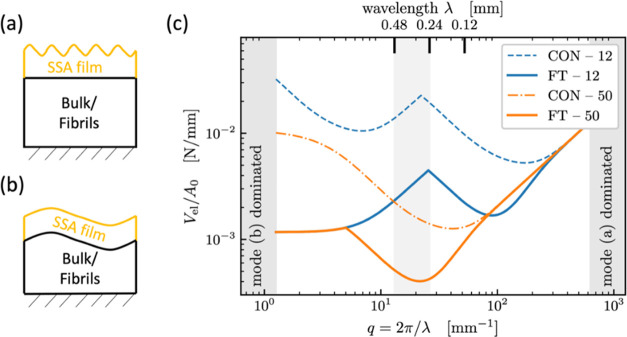
It is finally attempted to explain some of our observations in the light of theoretical concepts. It was recently found that rough surfaces, both random and sinusoidal, become sticky when their surface energy is more than half the elastic energy needed to bring the surfaces into conformal contact.47 Since the elastic energy for contacting nominally flat surfaces is dominated by the surface undulations near the “roll-off” wavelengths,48 it is sufficient to consider a single representative undulation with a wavelength near roll-off. While the exact treatment of a multilayered system would require complicated transfer-matrix techniques,49,50 simple scaling arguments are presented here. We approximate the mechanics of the fibril structure (with an areal density of 22.5%) as a homogeneous elastic medium with a Young’s modulus E that is 22.5% of that of the bulk and Poisson’s ratio of zero. It is further considered that surface undulation of wavelength λ penetrates roughly a distance λ/2π into a semi-infinite solid, which is sometimes referred to as Saint-Venant’s principle and is backed up by analytical solutions.51
Figure 10 illustrates two modes to be considered: When λ is small compared to the terminal layer thickness h = hlayer, the layer deforms elastically as if the body below, with much greater Young’s modulus, provided a rigid constraint (Figure 10a, mode a). Thus, the energy of deformation is given by52,53
| 2 |
where ũ is the displacement amplitude, E* = E/(1 – υ2) is the contact modulus, q = 2π/λ is the magnitude of the wave vector, and c(υ, qh) is a dimensionless geometric prefactor. At large wavelengths (relative to the film thickness, Figure 10b, mode b), the entire sample including the layer is fully deformed and follows the undulation of the counter surface. Since the bottom medium is much stiffer than the layer, we estimate this deformation energy by evaluating eq 2 only for the bulk/fibril body below the layer. In summary, we obtain Vel,mode(a) (q) = Vel,1 (q, hlayer, νlayer) and Vel,mode(b) (q) ≈ Vel,1 (q, hbottom, νbottom).
Figure 10.
Theoretical model cases for elastic bodies with a sinusoidal counter surface. (a) Mode a: wavelength λ much smaller than layer thickness, (b) mode b: wavelength λ substantially exceeds layer thickness, (c) calculated deformation energies (per area) as functions of wavelength λ or wave vector q. The underlying “bulk/fibril” material is assumed to be stiffer than the terminal layer, providing a rigid constraint. In agreement with the experiment, the best confirmation to a counter surface with a wavelength between 240 and 480 μm (lowest deformation energy) is predicted for FT—50 (shaded).
Figure 10c displays the calculated areal deformation energies as a function of wavelength for the two different terminal layer thicknesses with and without fibril structures. It is generally seen that, with increasing wavelength (decreasing wave vector), the deformation energy decreases at first and then increases again; there is hence a defined wavelength for which adhesion is expected to be optimal. This is a result of the trade-off between higher displacement gradients at low λ and near-incompressibility at large λ. In the experimental wavelength range near the roll-off of the PSD (Figure 2e), fibril structures are predicted to require less deformation energy; consequently, they will more easily form intimate adhesive contact and exhibit a higher pull-off stress. It is also seen that the difference between 12 and 50 μm layer thickness is more noticeable for control specimens (dashed and dash-dotted line, CON—12 and CON—50) than for the fibrillar structures (solid lines FT—12 and FT—50), matching the behavior visible in Figure 5a.
Considering the difference between the 12 and 50 μm film-terminated samples, we have also observed in the finite-element simulations (Figure 8b) that the thinner terminal layer creates higher stress concentrations reaching the interface to the counter surface. If the counter surface is considered rigid and the fibrils are treated as flat punches in contact with the film, a thickness of about twice the fibril radius can already be approximated as infinitely thick in linear elastic theory.52 This is roughly fulfilled by the 50 μm layer (FT—50), whereas in the FT—12 sample, the stress concentrations due to the fibrils will favor interfacial crack initiation and hence lead to earlier detachment. The fibrillar structure still improves adhesion in comparison to the control samples because it provides a more compliant background medium.6,54
Additionally, we estimated the conditions, in which mode a dominates at all wavelengths,52 i.e., the effect of the patterned background would become negligible. The terminal layer thickness for this condition is approximately 450 μm, which is larger than the fibril length.
5. Conclusions
The adhesion of fibrillar microstructures terminated by a soft film was investigated against surfaces of different roughness (from smooth to skin-like), as well as against sinusoidal model surfaces of varying wavelengths, with roughness Rz = 50 μm mimicking the skin. The effects of varying terminal layer thicknesses and subsurface microfibrils were investigated. The following conclusions can be drawn:
Improved tolerance to roughness: The film-terminated fibrillar microstructures exhibit improved adhesion to counter surfaces of finite roughness, typical of skin, in comparison to flat samples. Microstructured samples show decay of up to 43% with increasing roughness, while unstructured control samples have a decay of up to 98%. The reason is the better conformity of the microstructures to the surface topography due to their higher effective compliance. We presented a theoretical model of the interaction with a rough surface.
Threshold wavelength of the counter surface: Our experimental results suggest that, to ensure sufficient contact, the wavelength of the roughness must obey λ > 4D, where D is the fibril diameter. The empirical threshold is attributed to a geometrical impediment of the fibrils to achieve the furthest point in the counter surface. Above this limit, adhesion can be tuned by increasing the contact area through compressive preload. These results are in agreement with finite-element simulations, in which contact fraction during compression was evaluated.
Terminal layer thickness effect: A thinner terminal layer creates local stress concentrations and leads to earlier detachment. The thicker terminal layer reduces the influence of the stiffer background material, making the structure more compliant. A simple preliminary model consideration is presented to explain these effects.
Overload protection: When sufficiently compressed, the film-terminated microstructure exhibits elastic instability of the fibrils without loss in adhesion. This mechanism leads to a stress plateau, which protects the counter surface against overload and damage during application, a feature relevant for medical applications.
Acknowledgments
The authors thank Klaus Kruttwig for discussions in the preconceptualization and the previous work on film-terminated microstructures. Lars Pastewka is thanked for helpful discussion on the roughness and power spectrum analysis. Martin Müser is acknowledged for valuable input on the analytical discussions. Yue Wang and Julian Weiß are thanked for fabrication of rough surfaces. Joachim Blau is thanked for building the adhesion measurement setup. The authors thank Biesterfeld Spezialchemie GmbH (Hamburg, Germany) for providing polymers. Dr. Xuan Zhang acknowledges support by a Humboldt Research Fellowship for Postdocs. The research leading to these results has received funding from the European Research Council under the European Union’s HORIZON-EU.1.1 program/ERC PoC Grant Agreement No. 842 613, Advanced Grant “Stick2Heal” to E.A.
Author Contributions
G.M.L., X.Z., R.H., E.A.: conceptualization; G.M.L.: sample fabrication, adhesion measurements, microscopy; X.Z.: establishment of the simulation model; G.M.L., X.Z., and C.M.: writing—original draft; G.M.L., X.Z., C.M., R.H., and E.A.: review and editing. This manuscript was written through contributions of all authors. All authors have given approval to the final version of the manuscript.
The authors declare no competing financial interest.
References
- Kwak M. K.; Jeong H. E.; Suh K. Y. Rational Design and Enhanced Biocompatibility of a Dry Adhesive Medical Skin Patch. Adv. Mater. 2011, 23, 3949–3953. 10.1002/adma.201101694. [DOI] [PubMed] [Google Scholar]
- Tian L.; Zimmerman B.; Akhtar A.; Yu K. J.; Moore M.; Wu J.; Larsen R. J.; Lee J. W.; Li J.; Liu Y.; Metzger B.; Qu S.; Guo X.; Mathewson K. E.; Fan J. A.; Cornman J.; Fatina M.; Xie Z.; Ma Y.; Zhang J.; Zhang Y.; Dolcos F.; Fabiani M.; Gratton G.; Bretl T.; Hargrove L. J.; Braun P. V.; Huang Y.; Rogers J. A. Large-Area MRI-Compatible Epidermal Electronic Interfaces for Prosthetic Control and Cognitive Monitoring. Nat. Biomed. Eng. 2019, 3, 194–205. 10.1038/s41551-019-0347-x. [DOI] [PubMed] [Google Scholar]
- Chung H. U.; Kim B. H.; Lee J. Y.; Lee J.; Xie Z.; Ibler E. M.; Lee K. H.; Banks A.; Jeong J. Y.; Kim J.; Ogle C.; Grande D.; Yu Y.; Jang H.; Assem P.; Ryu D.; Kwak J. W.; Namkoong M.; Park J. B.; Lee Y.; Kim D. H.; Ryu A.; Jeong J.; You K.; Ji B.; Liu Z.; Huo Q.; Feng X.; Deng Y.; Xu Y.; Jang K. I.; Kim J.; Zhang Y.; Ghaffari R.; Rand C. M.; Schau M.; Hamvas A.; Weese-Mayer D. E.; Huang Y.; Lee S. M.; Lee C. H.; Shanbhag N. R.; Paller A. S.; Xu S.; Rogers J. A. Binodal, Wireless Epidermal Electronic Systems with in-Sensor Analytics for Neonatal Intensive Care. Science 2019, 363, eaau0780 10.1126/science.aau0780. [DOI] [PMC free article] [PubMed] [Google Scholar]
- Boyadzhieva S.; Sorg K.; Danner M.; Fischer S. C. L.; Hensel R.; Schick B.; Wenzel G.; Arzt E.; Kruttwig K. A Self-Adhesive Elastomeric Wound Scaffold for Sensitive Adhesion to Tissue. Polymers 2019, 11, 942 10.3390/polym11060942. [DOI] [PMC free article] [PubMed] [Google Scholar]
- Moreira Lana G.; Sorg K.; Wenzel G. I.; Hecker D.; Hensel R.; Schick B.; Kruttwig K.; Arzt E. Self-Adhesive Silicone Microstructures for the Treatment of Tympanic Membrane Perforations. Adv. NanoBiomed Res. 2021, 1, 2100057 10.1002/anbr.202100057. [DOI] [Google Scholar]
- Davis C. S.; Martina D.; Creton C.; Lindner A.; Crosby A. J. Enhanced Adhesion of Elastic Materials to Small-Scale Wrinkles. Langmuir 2012, 28, 14899–14908. 10.1021/la302314z. [DOI] [PubMed] [Google Scholar]
- Fischer S. C. L.; Arzt E.; Hensel R. Composite Pillars with a Tunable Interface for Adhesion to Rough Substrates. ACS Appl. Mater. Interfaces 2017, 9, 1036–1044. 10.1021/acsami.6b11642. [DOI] [PMC free article] [PubMed] [Google Scholar]
- Persson B. N. J.; Albohr O.; Creton C.; Peveri V. Contact Area between a Viscoelastic Solid and a Hard, Randomly Rough, Substrate. J. Chem. Phys. 2004, 120, 8779–8793. 10.1063/1.1697376. [DOI] [PubMed] [Google Scholar]
- Arzt E.; Quan H.; McMeeking R. M.; Hensel R. Functional Surface Microstructures Inspired by Nature—From Adhesion and Wetting Principles to Sustainable New Devices. Prog. Mater. Sci. 2021, 119, 1–105. 10.1016/j.pmatsci.2021.100778. [DOI] [Google Scholar]
- Hensel R.; Moh K.; Arzt E. Engineering Micropatterned Dry Adhesives: From Contact Theory to Handling Applications. Adv. Funct. Mater. 2018, 28, 1800865 10.1002/adfm.201800865. [DOI] [Google Scholar]
- Eisenhaure J.; Kim S. A Review of the State of Dry Adhesives: Biomimetic Structures and the Alternative Designs They Inspire. Micromachines 2017, 8, 1–38. 10.3390/mi8040125. [DOI] [Google Scholar]
- Cutting K. F. Impact of Adhesive Surgical Tape and Wound Dressings on the Skin, with Reference to Skin Stripping. J. Wound Care 2013, 17, 157–162. 10.12968/jowc.2008.17.4.28836. [DOI] [PubMed] [Google Scholar]
- Zulkowski K. Understanding Moisture-Associated Skin Damage, Medical Adhesive Related Skin Injuries and Skin Tears. Adv. Skin Wound Care 2017, 30, 372–381. 10.1097/01.ASW.0000521048.64537.6e. [DOI] [PubMed] [Google Scholar]
- Hwang I.; Kim H. N.; Seong M.; Lee S. H.; Kang M.; Yi H.; Bae W. G.; Kwak M. K.; Jeong H. E. Multifunctional Smart Skin Adhesive Patches for Advanced Health Care. Adv. Healthcare Mater. 2018, 7, 1800275 10.1002/adhm.201800275. [DOI] [PubMed] [Google Scholar]
- Karp J. M.; Langer R. Dry Solution to a Sticky Problem. Nature 2011, 477, 42–43. 10.1038/477042a. [DOI] [PMC free article] [PubMed] [Google Scholar]
- Fischer S. C. L.; Kruttwig K.; Bandmann V.; Hensel R.; Arzt E. Adhesion and Cellular Compatibility of Silicone-Based Skin Adhesives. Macromol. Mater. Eng. 2017, 302, 1600526 10.1002/mame.201600526. [DOI] [Google Scholar]
- Drotlef D. M.; Amjadi M.; Yunusa M.; Sitti M. Bioinspired Composite Microfibers for Skin Adhesion and Signal Amplification of Wearable Sensors. Adv. Mater. 2017, 29, 1701353 10.1002/adma.201701353. [DOI] [PubMed] [Google Scholar]
- Bae W. G.; Kim D.; Kwak M. K.; Ha L.; Kang S. M.; Suh K. Y. Enhanced Skin Adhesive Patch with Modulus-Tunable Composite Micropillars. Adv. Healthcare Mater. 2013, 2, 109–113. 10.1002/adhm.201200098. [DOI] [PubMed] [Google Scholar]
- Noderer W. L.; Shen L.; Vajpayee S.; Glassmaker N. J.; Jagota A.; Hui C. Y. Enhanced Adhesion and Compliance of Film-Terminated Fibrillar Surfaces. Proc. R. Soc. A 2007, 463, 2631–2654. 10.1098/rspa.2007.1891. [DOI] [Google Scholar]
- He Z.; Moyle N. M.; Hui C. Y.; Levrard B.; Jagota A. Adhesion and Friction Enhancement of Film-Terminated Structures against Rough Surfaces. Tribol. Lett. 2017, 65, 1–8. 10.1007/s11249-017-0935-4. [DOI] [Google Scholar]
- Jagota A.; Hui C. Y. Adhesion, Friction, and Compliance of Bio-Mimetic and Bio-Inspired Structured Interfaces. Mater. Sci. Eng., R 2011, 72, 253–292. 10.1016/j.mser.2011.08.001. [DOI] [Google Scholar]
- Glassmaker N. J.; Jagota A.; Hui C.-Y.; Noderer W. L.; Chaudhury M. K. Biologically Inspired Crack Trapping for Enhanced Adhesion. Proc. Natl. Acad. Sci. U.S.A. 2007, 104, 10786–10791. 10.1073/pnas.0703762104. [DOI] [PMC free article] [PubMed] [Google Scholar]
- Boyadzhieva S.; Sorg K.; Danner M.; Fischer S. C. L.; Hensel R.; Schick B.; Wenzel G.; Arzt E.; Kruttwig K. A Self-Adhesive Elastomericwound Scaffold for Sensitive Adhesion to Tissue. Polymers 2019, 11, 1–15. 10.3390/polym11060942. [DOI] [PMC free article] [PubMed] [Google Scholar]
- Korn V.; Surber C.; Imanidis G. Skin Surface Topography and Texture Analysis of Sun-Exposed Body Sites in View of Sunscreen Application. Skin Pharmacol. Physiol. 2017, 29, 291–299. 10.1159/000450760. [DOI] [PubMed] [Google Scholar]
- Adabi S.; Hosseinzadeh M.; Noei S.; Conforto S.; Daveluy S.; Clayton A.; Mehregan D.; Nasiriavanaki M. Universal in Vivo Textural Model for Human Skin Based on Optical Coherence Tomograms. Sci. Rep. 2017, 7, 17912 10.1038/s41598-017-17398-8. [DOI] [PMC free article] [PubMed] [Google Scholar]
- Jones I.; Currie L.; Martin R. A Guide to Biological Skin Substitutes The Function of Normal Skin. Br. J. Plast. Surg. Br. Assoc. Plast. Surg. 2002, 55, 185–193. 10.1054/hips.2002.3800. [DOI] [PubMed] [Google Scholar]
- Shahsavan H.; Zhao B. Biologically Inspired Enhancement of Pressure-Sensitive Adhesives Using a Thin Film-Terminated Fibrillar Interface. Soft Matter 2012, 8, 8281–8284. 10.1039/c2sm25795e. [DOI] [Google Scholar]
- Bai Y.; Jagota A.; Hui C. Y. Frictional Auto-Roughening of a Surface with Spatially Varying Stiffness. Soft Matter 2014, 10, 2169–2177. 10.1039/c3sm52878b. [DOI] [PubMed] [Google Scholar]
- Kroner E.; Blau J.; Arzt E. Note: An Adhesion Measurement Setup for Bioinspired Fibrillar Surfaces Using Flat Probes. Rev. Sci. Instrum. 2012, 83, 2–5. 10.1063/1.3675888. [DOI] [PubMed] [Google Scholar]
- Fischer S. C. L.; Boyadzhieva S.; Hensel R.; Kruttwig K.; Arzt E. Adhesion and Relaxation of a Soft Elastomer on Surfaces with Skin like Roughness. J. Mech. Behav. Biomed. Mater. 2018, 80, 303–310. 10.1016/j.jmbbm.2018.01.032. [DOI] [PMC free article] [PubMed] [Google Scholar]
- Eubel J. M.Design Und Herstellung Eines Haftsystem Zur Anwendung Auf Dem Trommelfell; Universität des Saarlandes, 2019. [Google Scholar]
- Koenig D. W.; Dvoracek B.; Vongsa R. In Vitro Prediction of in Vivo Skin Damage Associated with the Wiping of Dry Tissue against Skin. Skin Res. Technol. 2013, 19, 453–458. 10.1111/j.1600-0846.2012.00663.x. [DOI] [PubMed] [Google Scholar]
- Chen S.; Bhushan B. Nanomechanical and Nanotribological Characterization of Two Synthetic Skins with and without Skin Cream Treatment Using Atomic Force Microscopy. J. Colloid Interface Sci. 2013, 398, 247–254. 10.1016/j.jcis.2013.02.026. [DOI] [PubMed] [Google Scholar]
- Sanner A.; Nöhring W. G.; Thimons L. A.; Jacobs T. D. B.; Pastewka L. Scale-Dependent Roughness Parameters for Topography Analysis. Appl. Surf. Sci. Adv. 2022, 7, 100190 10.1016/j.apsadv.2021.100190. [DOI] [Google Scholar]
- Jacobs T. D. B.; Junge T.; Pastewka L. Quantitative Characterization of Surface Topography Using Spectral Analysis. Surf. Topogr.: Metrol. Prop. 2017, 5, 013001 10.1088/2051-672X/aa51f8. [DOI] [Google Scholar]
- Gujrati A.; Sanner A.; Khanal S. R.; Moldovan N.; Zeng H.; Pastewka L.; Jacobs T. D. B. Comprehensive Topography Characterization of Polycrystalline Diamond Coatings. Surf. Topogr.: Metrol. Prop. 2021, 9, 014003 10.1088/2051-672X/abe71f. [DOI] [Google Scholar]
- Wang A.; Müser M. H. On the Usefulness of the Height-Difference-Autocorrelation Function for Contact Mechanics. Tribol. Int. 2018, 123, 224–233. 10.1016/j.triboint.2018.02.002. [DOI] [Google Scholar]
- Dassault Systems S. C.ABAQUS 6.14 Documentation; Simulia Corp: Providence, RI, USA, 2014. [Google Scholar]
- Shahsavan H.; Zhao B. Bioinspired Functionally Graded Adhesive Materials: Synergetic Interplay of Top Viscous-Elastic Layers with Base Micropillars. Macromolecules 2014, 47, 353–364. 10.1021/ma4018718. [DOI] [Google Scholar]
- Stark S.; Begley M. R.; McMeeking R. M. The Buckling and Postbuckling of Fibrils Adhering to a Rigid Surface. J. Appl. Mech. 2013, 80, 041022 10.1115/1.4023107. [DOI] [Google Scholar]
- Tinnemann V.; Arzt E.; Hensel R. Switchable Double-Sided Micropatterned Adhesives for Selective Fixation and Detachment. J. Mech. Phys. Solids 2019, 123, 20–27. 10.1016/j.jmps.2018.09.003. [DOI] [Google Scholar]
- Barreau V.; Hensel R.; Guimard N. K.; Ghatak A.; McMeeking R. M.; Arzt E. Fibrillar Elastomeric Micropatterns Create Tunable Adhesion Even to Rough Surfaces. Adv. Funct. Mater. 2016, 26, 4687–4694. 10.1002/adfm.201600652. [DOI] [Google Scholar]
- Kroner E.; Paretkar D. R.; McMeeking R. M.; Arzt E. Adhesion of Flat and Structured PDMS Samples to Spherical and Flat Probes: A Comparative Study. J. Adhes. 2011, 87, 447–465. 10.1080/00218464.2011.575317. [DOI] [Google Scholar]
- Kruttwig K.; Moreira Lana G.; Moh K.; Arzt E.. Krafttollerante Struktur 2021103895.2.
- Purtov J.; Frensemeier M.; Kroner E. Switchable Adhesion in Vacuum Using Bio-Inspired Dry Adhesives. ACS Appl. Mater. Interfaces 2015, 7, 24127–24135. 10.1021/acsami.5b07287. [DOI] [PMC free article] [PubMed] [Google Scholar]
- Paretkar D.; Kamperman M.; Schneider A. S.; Martina D.; Creton C.; Arzt E. Bioinspired Pressure Actuated Adhesive System. Mater. Sci. Eng., C 2011, 31, 1152–1159. 10.1016/j.msec.2010.10.004. [DOI] [Google Scholar]
- Wang A.; Müser M. H. On the Adhesion between Thin Sheets and Randomly Rough Surfaces. Friction 2022, 10.1007/s40544-022-0644-3. [DOI] [Google Scholar]
- Wang A.; Müser M. H. Is There More than One Stickiness Criterion?. Friction 2022, 4–7. 10.1007/s40544-022-0644-3. [DOI] [Google Scholar]
- Charyulu M. K.Theoretical Stress Distribution in an Elastic Multi-Layered Medium; Iowa State University, 1964. [Google Scholar]
- Kajita S. Green’s Function Nonequilibrium Molecular Dynamics Method for Solid Surfaces and Interfaces. Phys. Rev. E 2016, 94, 1–9. 10.1103/PhysRevE.94.033301. [DOI] [PubMed] [Google Scholar]
- Sainsot P. Analytical Stresses in Rough Contacts. Proc. Inst. Mech. Eng., Part C 2011, 225, 274–279. 10.1243/09544062JMES2300. [DOI] [Google Scholar]
- Müller C.; Müser M. H. Analytical and Numerical Results for the Elasticity and Adhesion of Elastic Films with Arbitrary Poisson’s Ratio and Confinement. J. Adhes. 2022, 1–24. 10.1080/00218464.2022.2038580. [DOI] [Google Scholar]
- Carbone G.; Lorenz B.; Persson B. N. J.; Wohlers A. Contact Mechanics and Rubber Friction for Randomly Rough Surfaces with Anisotropic Statistical Properties. Eur. Phys. J. E 2009, 29, 275–284. 10.1140/epje/i2009-10484-8. [DOI] [PubMed] [Google Scholar]
- Martina D.; Creton C.; Damman P.; Jeusette M.; Lindner A. Adhesion of Soft Viscoelastic Adhesives on Periodic Rough Surfaces. Soft Matter 2012, 8, 5350–5357. 10.1039/c2sm07059f. [DOI] [Google Scholar]


