

Abstract
Sustainable and scalable fabrication of electrode materials with high energy and power densities is paramount for the development of future electrochemical energy storage devices. The electrode material of a supercapacitor should have high electrical conductivity, good thermal and chemical stability, and a high surface area per unit volume (or per unit mass). Researchers have made great efforts to use two-dimensional (2D) nanomaterials, but the separated 2D plates are re-stacked during processing for electrode fabrication, impeding the transport of ions and reducing the number of active sites. We developed a novel process for manufacturing thin and flexible electrodes using a 2D material (MXene,Ti3AlC2) and a conducting polymer (poly(3,4-ethylenedioxythiophene), PEDOT). Because the PEDOT layer is electrochemically synthesized, it does not contain the activator poly(styrene sulfonate). The electrospray deposition technique solves the restacking problem and facilitates the infilling of the gel electrolyte by forming a highly porous open structure across the entire electrode. In the PEDOT/MXene multilayered electrode, the double-layer capacitance increased substantially because of a dramatic increase in the number of accessible sites through the MXene layer. Although applied to solid supercapacitors, these new supercapacitors outperform most aqueous electrolyte supercapacitors as well as other solid supercapacitors.
1. Introduction
The recent development of wearable and flexible electronic products requires a solid-state, high-performance energy storage solution.1−5 As traditional energy storage devices, batteries have been used extensively in solid-state energy storage applications.3,4 However, they suffer from slow charge–discharge cycles because of their diffusion-controlled charge storage mechanism.3 The slow kinetics of this energy storage mechanism results in a low power density and limited life cycle.4 By contrast, supercapacitors, also known as ultracapacitors or electrochemical capacitors, have attracted broad attention over the past decades due to their distinct advantages over traditional rechargeable batteries such as higher energy density, longer life cycle, faster charge and discharge, better safety, less pollution, and no memory effect.5,6 Depending on their charge storage mechanism, supercapacitors can be classified into three types: electrical double-layer capacitors (EDLCs), which store charges by electrostatically adsorbing electrolyte ions onto the surface of electrode materials without charge transfer, and pseudocapacitors, which operate through a fast and reversible surface redox reaction. Unlike the mechanism of batteries, ions simply attach to the atomic structure of the electrodes, allowing for faster charging and discharging than batteries. The third type of supercapacitor with electrodes based on a combination of EDLCs and pseudocapacitors is known as a hybrid capacitor.6
Flexible solid-state supercapacitors (SSCs) for flexible electronics are commonly constructed by sandwiching a gel electrolyte between a pair of porous electrodes.1,7 The sustainable and scalable manufacture of electrode materials with high energy and power densities is paramount to the development of supercapacitors for future transportation and stationary electric grid applications.2,8 The electrode materials in supercapacitors should have high electrical conductivity, good thermal and chemical stability, and a high surface area per unit volume (or per unit mass).9 Researchers have devoted much effort to the use of two-dimensional (2D) nanomaterials with large surface area-to-volume ratios as high-performance electrode materials, but the restacking problem in the preparation process disrupts the transport of ions and lowers the number of active sites.10 Various nanostructured systems recently studied to increase the interlayer spacing of 2D materials or introduce porosity have limitations in applications for large-scale and continuous mass production of electrodes due to their complex processes.7−14
In our previous study, we used a simple electrodeposition technique to fabricate a highly uniform MXene (Ti3C2Tx; typically represented as Mn+1AXn, where M is an early transition metal, A is a group III or IV-A element, and X is C or N) pseudocapacitor electrode with a three-dimensional (3D) open-pore structure for supercapacitor applications (Figures S1 and S2).15 The fabricated micron-thickness electrodes without the use of any additives or binders exhibited an outstanding specific capacitance of 400 F g–1 at a scan rate of 10 mV s–1 in H2SO4 aqueous electrolyte and maintained 85% of its value at scan rates as high as 1000 mV s–1.15 Though the electrode exhibited excellent cycling stability, it meets the thickness limit. Recently, a lot of research has been done on supercapacitors using MXene and conductive polymers, but their performance has not been quite impressive.12−14 Also, they were not SSCs and the preparation process was quite complex. In the present study, we further explored searching for a highly efficient electrode with gel electrolyte (a solid-state supercapacitor) for practical applications. We devised a novel process for manufacturing thin and quite flexible nanocomposite electrodes using an MXene and a conducting polymer (poly(3,4-ethylenedioxythiophene), PEDOT). It should be emphasized that we did not use the activator (poly(styrene sulfonate)) to enhance the conductivity because it can increase the charge transfer resistance.12−14 Instead, we applied an electrochemical synthetic method.
2. Results and Discussion
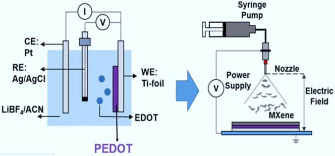
We prepared PEDOT/MXene multilayered composite electrodes with full 3D open-pore structures by depositing a separate MXene layer using the electrospray deposition (ESD) technique onto the electropolymerized PEDOT layer (Figure 1). As described above, poly(styrene sulfonate) (PSS), a general PEDOT conductive activator, can increase charge transfer resistance, so it was not included in the electrode by synthesizing PEDOT using an electropolymerization method.16 However, the gel electrolyte could fully activate the PEDOT to derive high electrical conductivity, as shown later.12−14 The compositions of the composite electrodes are listed in Table 1. Under electrochemical polymerization, the PEDOT layer directly grows on the Ti foil current collector without a binder, which results in a reduction of the contact resistance between the PEDOT and the current collector. Because of the fractal growth mode, the PEDOT layer exhibits a porous structure into which the gel electrolyte can seep, resulting in a large electrochemically active area and efficient ion diffusion (Figure 1b,c).12,14 Like the PEDOT layer, the porous structure of the MXene layer can be easily filled with a gel electrolyte, providing an efficient ion diffusion pathway and a large electrochemically active surface area (Figure 1d,e).19Figure 1b,c shows the morphological change of the PEDOT layer from a highly porous network between small clusters to a densely packed sphere-like granule with increasing polymerization time. This morphological change of the PEDOT with increasing polymerization time affects the gel electrolyte filling, electrochemically active area, electrochemical contact between active materials, and thus the electrochemical performance of the SSC device.19,20 Because of its thin layers, it is very flexible (Figure S1e) not to show any detachment of the PEDOT layer or a crack after many times of repeated bending tests.
Figure 1.

Fabrication process and morphology: (a) schematic illustration of the fabrication process for PEDOT/MXene layered composite electrodes. Morphology of PEDOT and PEDOT/MXene electrodes: scanning electron microscopy (SEM) images from the surface of (b) PEDOT-30, (c) PEDOT-60, and (d) PEDOT-60/MX. (e) Cross-sectional image of PEDOT-90/MX. (See Figure S1 for SEM and TEM images of MXen only and the SEM image of PEDOT90, and Figure S2 for the MXene structure identification).
Table 1. Composition Characteristics and Capacitance of PEDOT, MXene, and PEDOT/MXene Layered Composite Electrodes.
| sample | PEDOT polymerization time [s] | spraying volume of MXene [mL] | capacitance [mF cm–2]a | capacitance [F g–1]a |
|---|---|---|---|---|
| MX | 0 | 20 | 45 | 383 |
| MX2 (twice MXene volume sprayed) | 0 | 40 | 74 | 381 |
| PEDOT30/MX(30 s PEDOT polymerization) | 30 | 20 | 57 | 335 |
| PEDOT60/MX(60 s PEDOT polymerization) | 60 | 20 | 69 | 281 |
| PEDOT90/MX(90 s PEDOT polymerization) | 90 | 20 | 80 | 260 |
The capacitance was evaluated at a scan rate of 10 mV s–1.
The colloidal stability of the MXene suspension is attributed to surface functional groups (such as −OH, −O, −F, and −Cl) with negative ζ potentials.21 During the ESD deposition of MXene suspension, rapid evaporation of solvents in an aerosolized MXene solution induces capillary forces on MXene flakes, producing a crumpled morphology of the MXene flakes that prevent re-aggregation of the flakes and forming a porous structure of the entire MXene layer (Figure 1d).15Figure 1e shows that the gel electrolyte smears into the entire crumpled MXene layer and the porous PEDOT layer without any voids.22 The porous structure allows complete access by the electrolyte ions to store charges by pure physical adsorption. The uniform distribution of the gel electrolyte was confirmed by energy-dispersive spectroscopy (EDS) (Figure S3). Porous electrodes help maximize the stored energy density and promote ion transport, which increases the power density.18,19
Cyclic voltammetry (CV) measurements were performed using a symmetric two-electrode configuration with poly(vinyl alcohol)(PVA)/H3PO4 gel electrolyte. Figure 2a shows the comparative area-normalized CV curves recorded at a scan rate of 50 mV s–1 for the prepared MXene-only (MX and MX2) and PEDOT/MXene composite electrodes. All of the curves show a nearly rectangular shape, implying that the charging and discharging process of the fabricated electrodes exhibits nearly ideal capacitive behavior.23 The square-shaped CV curve for the PEDOT-60/MX electrodes was maintained up to a high scan rate of 200 mV s–1 (Figure 2b). Because of the superior electrical conductivity and capacitive charge storage properties of the MXene, the current contributions from the PEDOT and the MXene layer are perfectly added, even at high scan rates.23 The change in shape from rectangular to leaf-like at higher scan rates is attributable to the ions lacking sufficient time to reach the electrode, which reduces their interaction with the electrode surface, resulting in reduced capacitance (Figure 2c).17 Other factors, such as increased active material resistance and active material electrolyte interfacial resistance, and long ion diffusion lengths, also contribute to the rapid decrease in specific capacitance at high scan rates.2,12 The areal capacitance of the PEDOT/MXene layered composite increased from 45 mF cm–2 for the MXene electrode to 80 mF cm–2 for the PEDOT-90/MXene electrode at a scan rate of 10 mV s–1. The high rate capability of the PEDOT (Figure S4) and the efficient charge transfer between the PEDOT and the MXene layer make the areal capacitance of all of the PEDOT/MXene layered composites greater than that of the MXene-only electrode.15 As a result, the PEDOT-90/MX electrode shows superior areal capacitance and rate capability even compared to the MX2 electrode containing twice as much MXene. Although the gravimetric specific capacitance of the PEDOT/MXene layered composite electrodes decreases with the inclusion of the PEDOT layer due to the much lower gravimetric specific capacitance of PEDOT in comparison with that of MXene (Figure S4), it becomes comparable to that of the MXene-only electrode at high scan rates. This is attributed to the additive effect between the high rate capability of the PEDOT layer and the effective charge transfer between the PEDOT and the MXene layers (Figure 2d). However, the PEDOT-90/MX SSC shows a larger decrease of the capacitance at high scan rates, implying that there is an optimal polymerization time (∼60 s).
Figure 2.

Cyclic voltammogram, SSC capacitance, and Nyquist plots: (a) cyclic voltammograms of MXene and PEDOT/MXene layered composite electrodes at a scan rate of 50 mV s–1. (b) Cyclic voltammograms of PEDOT-60/MX at different scan rates. (c) Area-normalized capacitance vs scan rate and (d) gravimetric specific capacitance vs scan rate of MXene (MX and MX2, which contains twice as much MXene) and PEDOT/MXene layered composite electrodes. The lines are a guide to the eye. (e) Nyquist plot for a PEDOT-90/MXene sample and its fitting by the Randles model (inset in the figure).
The decrease in rate capability in Figure 2c,d is attributed to inefficient ion diffusion.22−24 Nonetheless, the charge transfer between the PEDOT and MXene layers in the composites is quite efficient and sufficiently fast to maintain the electrochemical performance of the MXene.25 We used electrical impedance spectroscopy (EIS) to gain insights into the effects of the resistance and capacitive elements on the performance of the supercapacitor (see the Supporting Information (SI) and Table S1).26−29Figure 2e shows the Nyquist plots in the frequency range of 100 kHz to 10 MHz, as recorded at an open-circuit potential of 5 mV. All of the Nyquist plots show two overlapping semicircles in the high-frequency region followed by a straight line in the low-frequency region, representing the capacitive behavior of the electrode.9,30 For quantitative analysis, the Nyquist plots were fitted using the Randles equivalent electrical circuit model shown as the inset in Figure 2e (see Table S1 for details).28,43
The charge storage mechanisms of the PEDOT/MXene layered composites can be quantified more accurately using Dunn’s method which deconvolutes the contributions of the surface-reaction current and ion diffusion-controlled current (Figure S6 and response current analysis therein).31,42 The change in the ratio of surface-reaction (capacitive) contribution in the electrodes is less than 5% for all electrodes except the PEDOT-90/MX electrode. This indicates that at a slow scan rate, the current by the surface reaction of the device occupies most of it, and the improvement of the current by diffusion-controlled contribution is very small. Thus, the fast rate capability is attributable to the enhanced electrochemical active area and efficient ion diffusion in the pore structure of the PEDOT/MXene layered composite. The pores of the 3D network-like structure are fully exposed to the electrolyte, providing easy access for ions in the double-layer formed between the electrode and the electrolyte (Figures 1e and S1). By contrast, for the PEDOT-90/MX electrode, the change in the surface-reaction contribution of the electrode is greater than 10% due to a reduction of real contact area and charge-transfer efficiency between the MXene and the PEDOT in the composite electrodes (Figures 1c and S6). This is also reflected in the Warburg element of the equivalent circuit model which represents the diffusion of ions into the pores during the transition from the high-frequency semicircle to the mid-frequency spike in the Nyquist plots.28 As the PEDOT polymerization time increases, the Warburg impedance increases significantly for the PEDOT electrode because of a change in the porous structure (Table S1).43
The low conductivity of the polyelectrolytes increases the internal resistance and barricades the energy density and the power density of the supercapacitors.11 We address it by introducing a salt into gel polymer electrolytes to improve the ionic conductivity and thus the electrochemical performance of SSCs by the additional capacitive current.30,32 LiCF3SO3, one of the most commonly used salts, was used. The results of various amounts of LiCF3SO3 addition (0–0.3 M) to the H3PO4/PVA electrolyte are summarized in Figure 3. The addition of LiCF3SO3 results in more charge carriers from H3PO4 and LiCF3SO3, leading to improved ionic conductivity and a significant distortion of the broad redox plateau in the rectangular-shaped curve (Figure 3a,b).30 The areal capacitance values calculated from the resultant CV curves at a scan rate of 10 mV s–1 are 69, 83, 106, 115, 102, and 74 mF cm–2 for the PEDOT-60/MX SSCs based on H3PO4/PVA and H3PO4/PVA/LiCF3SO3 (0.05, 0.1, 0.15, 0.2, and 0.3 M) electrolytes, respectively (Figure 3c). The corresponding specific capacitance values were calculated as 281, 336, 428, 465, 415, and 301 F g–1, respectively (Figure 3d). The device with 0.15 M LiCF3SO3 showed maximum areal and gravimetric specific capacitance values of 115 mF cm–2 and 465 F g–1, respectively. The concentration of 0.15 M is the optimal concentration of LiCF3SO3 because excess CF3SO3– ions in the H3PO4/PVA gel electrolyte increase the viscosity of the electrolyte and restrict the ion flow, making it difficult for the ions to access the active sites of the porous electrode.33
Figure 3.

Cyclic voltammograms, capacitance, and Nyquist plots of PEDOT-60/MXene/Salt: (a) cyclic voltammograms of PEDOT-60/MX-layered composite electrodes varying the concentration of LiCF3SO3 in H3PO4/PVA at a scan rate of 10 mV s–1. (b) Cyclic voltammograms of PEDOT-60/MX using 0.15 M LiCF3SO3-added H3PO4/PVA electrolyte at different scan rates. (c) Area-normalized capacitance vs scan rate and (d) gravimetric specific capacitance vs scan rate of PEDOT-60/MX-layered composite electrodes varying the concentration of LiCF3SO3 in H3PO4/PVA. Because of the capacitance decrease at high scan rates, PEDOT-60/MX was used rather than PEDOT-90/MX. The lines are a guide to the eye. (e) Nyquist plots (high-frequency region) and (f) Bode plots of PEDOT-60/MX-layered composite electrodes varying the concentration of LiCF3SO3 in H3PO4/PVA.
A decrease in areal and gravimetric specific capacitance of the device with increasing scan rate is observed for all of the salt-added samples, mainly because of the diminished involvement of active materials in the electrode by the polarization at the active material/electrolyte interfaces.34 The diffusion rate of ions is insufficient to match the electrochemical behavior of LiCF3SO3 in the gel electrolyte, which decreases the rate capability of the reaction compared with that of the bare H3PO4/PVA system (Figure 2c,d).34,35 This can be confirmed by EIS analysis of the Nyquist plots (Figure 3e and Table S1). The obtained Rsol values (the bulk resistance of the electrolyte) decrease with increasing the salt concentration due to the improved ionic conductivity. However, the Rct value (charge transfer resistance) increases with increasing LiCF3SO3 content due to the increased resistance at the electrode and electrolyte interface caused by the additional Faraday reaction of LiCF3SO3 and the involvement of the electrochemically active material (Table S1).36 Even though the SSCs show large Rct values, they can enhance the capacitance. The analysis by Dunn’s method shows an increase in the diffusion-controlled contribution at slow scan rates for all concentrations, originating from the additional diffusion-controlled reaction of LiCF3SO3 (Figure S7).31,36
The slope of the vertical
line in the low-frequency region corresponding
to ideal capacitance behavior was gradually changed with the concentration
of the salt because of the additional faradaic reaction of LiCF3SO3 (Figure 3e). The straight line in the lower frequency region of the
Nyquist plots represents the diffusion-controlled process of the devices.30 In the case of the H3PO4/PVA sample, the line is close to 90°, indicating the ideal
capacitive behavior of the device. The lines deviate from the imaginary
axis for the salt-added samples, demonstrating the emergence of additional
diffusion-controlled behavior in the salt-added SSCs.18 Bode plots for all SSCs reveal phase angles between −85
and −60° at the lowest frequency of 0.01 Hz (Figure S5).37 The
salt-added SSCs show a broad peak at the high-frequency region, which
shifts to a lower frequency region upon the addition of more LiCF3SO3 to the gel electrolyte, demonstrating an increase
in the diffusion resistance of ions into the electrode due to ion
aggregation, which reduces the electrochemical performance of devices
with the addition of a large amount of salt to the gel electrolyte.35 This effect is quantitatively confirmed by the
characteristic kinetic frequency ( ) at which the capacitive and the resistance
impedances are equal, which corresponds to a phase angle of −45°
in the Bode plot.37,38 At this point, the cell is discharged
with an efficiency of 50%. This low-frequency response means an increase
in the diffusion resistance of ions into the electrode, leading to
a slow ion diffusion and, thus, to a reduction of the electrochemical
performance of SSCs. Because of these two opposite effects, there
appears the optimum concentration of the salt for the electrochemical
performance.
) at which the capacitive and the resistance
impedances are equal, which corresponds to a phase angle of −45°
in the Bode plot.37,38 At this point, the cell is discharged
with an efficiency of 50%. This low-frequency response means an increase
in the diffusion resistance of ions into the electrode, leading to
a slow ion diffusion and, thus, to a reduction of the electrochemical
performance of SSCs. Because of these two opposite effects, there
appears the optimum concentration of the salt for the electrochemical
performance.
A Ragone plot was constructed to compare the areal energy and power density values for all SSC devices in a symmetric full-cell configuration (Figure 4a,b).2,19 The highest area-normalized energy density of 10.19 μWh cm–2 was recorded at a power density of 0.46 mW cm–2 for a PEDOT-60/MX sample with 0.15 M LiCF3SO3 in H3PO4/PVA gel electrolyte. In addition, the maximum power density of 21.93 mW cm–2 was obtained with an energy density of 4.87 μWh cm–2 by the same electrode (Table S1). Notably, the weight normalized energy and power densities are much greater than those of all of the H3PO4/PVA-based SSCs. To verify the charge–discharge cycle durability of the device, the PEDOT-60/MX electrode was subjected to 10 000 charge–discharge cycles in a potential range of 0.8 V at a current density of 3 mA cm–2 using bare and 0.15 M LiCF3SO3-added H3PO4/PVA gel electrolytes (Figure 4c). The inset shows a comparison of the galvanostatic charge–discharge curves measured at a fixed current density of 3 mA cm–2. No IR drop is evident in the curve of the PEDOT-60/MX (H3PO4/PVA) SSC, which means that no electrical potential along the path of the current flowing in an electrical circuit is lost and that the device exhibits little pseudocapacitance behavior.6,9 By contrast, the salt-added SSC shows a slightly distorted triangle with a small IR drop, similar to the curve of a pseudocapacitor.32,33 Like the CV curves, the charge–discharge curve becomes wider with extended discharge time, which is consistent with the EIS results, illustrating superior performance (Table S1). The retention of the shape of the discharge curves with little potential drop even at higher current densities indicates good EDLC behavior.6
Figure 4.

Ragone plots and cycling durability: (a, b) Ragone plot for PEDOT-60/MX-layered composites using LiCF3SO3-added H3PO4/PVA gel electrolytes compared with other symmetric supercapacitors using H3PO4/PVA gel electrolyte. The lines are a guide to the eye. (c) Cycling durability of PEDOT-60/MX with bare and 0.15 M LiCF3SO3-added H3PO4/PVA electrolyte measured at a fixed current density of 3 mA cm–2 for 10 000 cycles (inset: galvanostatic charge–discharge cycle curves at a current density of 15 A g–1). (d) Ragone plot comparison for various electrochemical energy storage devices of present-day technology (The background graph was adopted from ref (39). Copyright: 2014 American Chemical Society).
After 10 000 cycles, the H3PO4/PVA sample retained ∼90% of the initial areal capacitance while the salt-added sample showed ∼70% capacitance retention, possibly due to the increase in ion aggregation which reduces ion migration and diminishes the redox behavior of the electrolyte.30,39 Nevertheless, the performance of the 0.15 M salt-added capacitor is truly outstanding. In addition to the excellent energy density, it exhibits unprecedented high power density.40 In terms of the energy density (maximum 20.65 Wh kg–1 at 10 mV s–1) and the power density (45.45 kW kg–1 at 1000 mV s–1), the SSC with the optimal salt amount (0.15 M) outperforms most aqueous electrolyte supercapacitors, as well as most reported SSCs (Figure 4d).2,39,41 The energy density is even comparable to that of a Li-ion capacitor, but the power density far exceeds that of a Li-ion supercapacitor. Also, this SSC performs significantly better than the SSC composed of Ti3C2Tx/PEDOT prepared together by in situ polymerization.25
3. Conclusions
In summary, flexible all-solid-state supercapacitors with novel structured electrodes were fabricated via the electrochemical polymerization of PEDOT and subsequent electrospray deposition of MXene onto the PEDOT layer. The combination of the fractal characteristics of the electropolymerized PEDOT and the crumpled MXene flakes form a highly porous open structure across the entire electrode. This porous structure enables easy infilling of a gel electrolyte without forming voids, leading to a large electrochemically active area and efficient ion diffusion routes for improved electrochemical performance. Although PEDOT did not contain PSS as an activator, it was able to have sufficiently high conductivity due to complete contact with the gel electrolyte, which penetrated well into the porous structure of PEDOT to provide high conductivity. The electrochemical capacitance of the device was further enhanced by adding a salt (LiCF3SO3) to the gel polymer electrolyte. The addition of the optimal amount of the salt (0.15 M) greatly promoted both the ionic conductivity of the electrolyte and additional current, resulting in a surprisingly excellent capacitance. It outperforms most aqueous electrolyte supercapacitors as well as most reported SSCs. The fabrication process of the PEDOT/MXene composite electrode is very simple, inexpensive, and can be easily applicable to the practical production of large-area flexible SSCs.
4. Experimental Section
4.1. Synthesis of the Ti3C2Tx Mxene
Few-layer Ti3C2Tx (MXene) flakes were synthesized by chemical etching from their precursor Ti3AlC2 MAX phase using HF-forming solution which contains metal fluoride salts (LiF) and HCl as described elsewhere.15 Ti3AlC2 (4 g, Carbon, Ukraine, <40 μm) powder was slowly added into the LiF (2.68 g) and HCl (6 M, 40 mL) mixture and kept at 45 °C for 48 h under constant stirring. The etched solution is highly acidic and washed with Ar gas purged deionized (DI) water using centrifugation at 3500 rpm for 10 min per cycle until the pH of the supernatant reached neutral.6 The collected sediment was dispersed in 500 mL of DI water and probe-sonicated (500 W, S-4000, Mixonix) for 1 h in an ice-cooled bath under Ar gas flow to prevent oxidation of MXene. The delaminated MXene solution was centrifuged for 10 min at 3500 rpm, and the collected supernatant was freeze-dried for further use.
4.2. Electrochemical Polymerization of Poly(3,4-ethylenedioxythiophene)
The titanium foil (Ti foil) was immersed in a solution containing 43 μL of 3,4-ethylenedioxythiophene (EDOT, 97%, Sigma-Aldrich) and 20 mL of 0.1 M LiBF4/acetonitrile (ACN). Then, the electrochemical polymerization was carried out in a three-electrode configuration, where platinum (Pt) plate and Ag/AgCl in 3 M KCl were used as the counter electrode and reference electrode, respectively. The PEDOT was polymerized under a constant potential of 1.5 V (vs Ag/AgCl) for different deposition times. The as-prepared PEDOT electrodes were carefully washed with ACN to remove the extra EDOT and LiBF4 followed by drying in air at room temperature for 12 h.
4.3. Fabrication of Electrospray-Deposited MXene Electrode15
The spraying solution was freeze-dried. MXene powder (60 mg) was dispersed in a 40 mL solvent mixture of DI water/ethanol(EtOH) (5:5 v/v). The suspension was probe-sonicated for 30 min in an ice-cooled bath under Ar gas flow to get stable dispersion. A stable MXene suspension was then pumped out of a 30G stainless steel needle at a rate of 3 mL h–1. The solution aerosolized at the tip of the needle under an electric potential of 18 kV. The distance between the tip of the nozzle and the as-prepared PEDOT-coated Ti foil (or just Ti foil) current collector was 13 cm. A postannealing process at 150 °C for 2 h under flowing Ar was then applied to adhere the MXene flakes to each other by sintering effect.
4.4. Fabrication of the Flexible Solid-State Symmetric Supercapacitor
The supercapacitors were fabricated through the assembly of PVA/H3PO4 gel electrolyte-coated Ti3C2Tx/PEDOT composite electrodes (Figure 1). The PVA/H3PO4 gel electrolyte is prepared by mixing 10 g of PVA powder with 100 mL of 1 M H3PO4 under stirring at 90 °C until the mixture becomes transparent. The gel electrolyte was cast onto the surface of PEDOT/MXene layered composites. For solid-state application, various PVA-based gel electrolytes have been applied using a mixture of acid, base, and salts.30,42 Even though they showed comparable achievements, drawbacks such as low ionic conductivity and lower level of capacitance are still remaining.41 Recently, many researchers have explored salt additives to gel polymer electrolytes for energy storage applications which efficiently improve the ionic conductivity and add additional capacitance into the supercapacitor enhancing electrochemical performance.30 In this work, lithium trifluoromethanesulfonate (LiCF3SO3) was applied as a salt additive in PVA/H3PO4 gel electrolyte which promotes both ionic conductivity of the electrolyte and capacitance value. After attaining transparent H3PO4/PVA gel solution, 0.05, 0.1, 0.15, 0.2, and 0.3 M LiCF3SO3 were added to this H3PO4/PVA gel solution and stirred for 30 min at the same temperature. The solution state LiCF3SO3/H3PO4/PVA gel electrolyte was directly coated on the PEDOT/MXene layered composite electrodes using a doctor blade and dried. The fabricated SSCs are very thin and very flexible (Figure S1e). No binder was applied, but the electrode and the entire SSC devices were flexible, and even after 10 bendability tests, no peeling or cracking occurred in the electrode or SSC. The flexible SSC manufactured here shows that the change in electrochemical performance was not notable after repeated bending 10 times. No separate mechanical flexibility test was done.
4.5. Chemical and Electrochemical Characterization
The morphological information of the samples was characterized by field emission scanning electron microscopy (FE-SEM, Nova Nano SEM 200, FEI). The X-ray diffraction (XRD) patterns were recorded on a powder diffractometer (D8 Advance, Bruker, Germany) equipped with a Cu K-α radiation source from 5 to 60° at a step rate of 2 ° min–1 (Figure S2 in the Supporting Information). The basic electrochemical properties of the devices were measured using a VMP3 potentiostat (Biologic, France). The specific capacitances were calculated based on the integrated area of the cyclic voltammograms. Electrochemical impedance spectroscopy (EIS) experiments were performed at open-circuit potential (OCP), with a 5 mV amplitude, and in the frequency range of 10 mHz to 100 kHz. Cycle stability was performed at a fixed current density of 3 mA cm–2 in the voltage range of 0–0.8 V.
Acknowledgments
Support from the Research Institute of Advanced Materials (RIAM) at Seoul National University and the Technology Innovation Program (no. 20015971, Development of piezoelectric fluoropolymers and their applied technology) funded by the Ministry of Trade, Industry & Energy (#20015971, MOCIE, Korea) is greatly appreciated. The authors appreciate Dr. Dong Young Kim at Korea Institute of Science and Technology for helpful discussions and some experimental facilities.
Supporting Information Available
The Supporting Information is available free of charge at https://pubs.acs.org/doi/10.1021/acsomega.2c04822.
SEM images for Ti3AlC2 (MAX), etched Ti3AlC2, and delaminated 2D Ti3C2Tx sheets, TEM images of the Mxene, a photograph of the fabricated flexible SSC showing the flexibility, and SEM image of PEDOT90 electrode (Figure S1); XRD patterns for Ti3AlC2 (MAX), etched MAX, and delaminated 2D Ti3C2Tx sheets (Figure S2);15 cross-sectional SEM images and their corresponding energy-dispersive spectroscopy (EDS) scans from the cross section of PEDOT-30/MX and PEDOT-90/MX (Figure S3); electrochemical performance of PEDOT single-layer electrodes varying electrochemical polymerization time, cyclic voltammograms at a scan rate of 50 mV s–1, areal capacitance vs scan rate and gravimetric specific capacitance vs scan rate, and EIS analysis by Randle’s equivalent circuit model (Figure S4); Nyquist plots shifted to compare the Rct values (Figure S5); response currents for the H3PO4/PVA electrolytes and response currents for the salt-added electrolytes (Figures S6 and S7); and equivalent circuit parameters and performance of the cells in the Ragone plot; response current analysis by Dunn’s method (Table S1) (PDF)
Author Present Address
† R&D Center, SK Hynix, Gyungchungdaero 2091, Bubalup, Icheonsi, Gyunggido, 17336 Korea
Author Contributions
The research strategy was set up by Seo. All of the experimental works were done by Cho and Lim. The manuscript was written by Cho and Seo. All authors have approved the final version of the manuscript.
The authors declare no competing financial interest.
Notes
§ S.C. and J.L. contributed equally.
Supplementary Material
References
- Pomerantseva E.; Bonnacorso F.; Feng X.; Cui Y.; Gogotsi Y. Energy storage: The future enabled by nanomaterials. Science 2019, 366, eaan8285 10.1126/science.aan8285. [DOI] [PubMed] [Google Scholar]
- Simon P.; Gogotsi Y. Perspectives for electrochemical capacitors and related devices. Nat. Mater. 2020, 19, 1151–1163. 10.1038/s41563-020-0747-z. [DOI] [PubMed] [Google Scholar]
- Xie J.; Liu Y. A retrospective on lithium-ion batteries. Nat. Commun. 2020, 11, 2499 10.1038/s41467-020-16259-9. [DOI] [PMC free article] [PubMed] [Google Scholar]
- Al Shaqsi A. Z.; Sopian K.; Al-Hinai A. Review of energy storage services, applications, limitations, and benefits. Energy Rep. 2020, 6, 288–306. 10.1016/j.egyr.2020.07.028. [DOI] [Google Scholar]
- Dubal D. P.; Chodankar N. R.; Kim D.; Gomez-Romero P. Towards flexible solid-state supercapacitors for smart and wearable electronics Chem. Soc. Rev. 2018, 47, 2065–2129. 10.1039/C7CS00505A. [DOI] [PubMed] [Google Scholar]
- Kim B. K.; Sy S.; Yu A.; Zhang J.. Handbook of Clean Energy Systems; Jinyue Yan., Ed.; Wiley, 2015; pp 1–25, 978-1-118-38858-7, 10.1002/9781118991978.hces112. [DOI] [Google Scholar]
- Yang Y. A mini-review: emerging all-solid-state energy storage electrode materials for flexible devices. Nanoscale 2020, 12, 3560–3573. 10.1039/C9NR08722B. [DOI] [PubMed] [Google Scholar]
- González A.; Goikolea E.; Barrena J. A.; Mysyk R. Review on supercapacitors: Technologies and materials. Renewable Sustainable Energy Rev. 2016, 58, 1189–1206. 10.1016/j.rser.2015.12.249. [DOI] [Google Scholar]
- Wang G.; Zhang L.; Zhang J. A review of electrode materials for electrochemical supercapacitors. Chem. Soc. Rev. 2012, 41, 797–828. 10.1039/C1CS15060J. [DOI] [PubMed] [Google Scholar]
- Xia Y.; Mathis T. S.; Zhao M.; Anasori B.; Dang A.; Zhou Z.; Cho H.; Gogotsi Y.; Yang S. Thickness-independent capacitance of vertically aligned liquid-crystalline MXenes. Nature 2018, 557, 409–412. 10.1038/s41586-018-0109-z. [DOI] [PubMed] [Google Scholar]
- Murali G.; Rawal J.; Modigunta J. K. R.; Park Y. H.; Lee J.-H.; Lee S.-Y.; Park S.-J.; In I. A review on MXenes: new-generation 2D materials for supercapacitors. Sustainable Energy Fuels 2021, 5, 5672–5693. 10.1039/D1SE00918D. [DOI] [Google Scholar]
- Idumah C. I.; Ezeani O. E.; Okonkwo U. C.; Nwuzor I. C.; Odera S. R.. Novel Trends in MXene/Conducting Polymeric Hybrid Nanoclusters J. Cluster Sci. 2022 10.1007/s10876-022-02243-4. [DOI]
- Boota M.; Gogotsi Y. MXene–conducting polymer asymmetric pseudocapacitors. Adv. Energy. Mat 2019, 9, 1802917 10.1002/aenm.201802917. [DOI] [Google Scholar]
- Qin L.; Tao Q.; El-Ghazaly A.; Fernandez-Rodriguez J.; Persson JÅ.; Rosen P. O.; Zhang F. High-performance ultrathin flexible solid-State supercapacitors based on solution processable Mo1.33C MXene and PEDOT:PSS. Adv. Funct. Mater. 2017, 28, 1703808 10.1002/adfm.201703808. [DOI] [Google Scholar]
- Cho S.; Kim D. Y.; Seo Y. Binder-free high-performance MXene supercapacitors fabricated by a simple electrospray deposition technique. Adv. Mater. Interfaces 2020, 7, 2000750 10.1002/admi.202000750. [DOI] [Google Scholar]
- Liu X.; Dai X.; Wei G.; Xi Y.; Pang M.; Izotov V.; Klyui N.; Havrykov D.; Ji Y.; Guo Q.; Han W. Experimental and theoretical studies of nonlinear dependence of the internal resistance and electrode thickness for high performance supercapacitor. Sci. Rep. 2017, 7, 45934 10.1038/srep45934. [DOI] [PMC free article] [PubMed] [Google Scholar]
- Li X.; Shao J.; Kim S.; Yao C.; Wang J.; Miao Y.; Zheng Q.; Sun P.; Zhang R.; Braun P. V. High energy flexible supercapacitors formed via bottom-up infilling of gel electrolytes into thick porous electrodes. Nat. Commun. 2018, 9, 2578 10.1038/s41467-018-04937-8. [DOI] [PMC free article] [PubMed] [Google Scholar]
- Purkait T.; Singh G.; Kumar D.; Singh M.; Dey R. S. High-performance flexible supercapacitors based on electrochemically tailored three-dimensional reduced graphene oxide networks. Sci. Rep. 2018, 8, 640 10.1038/s41598-017-18593-3. [DOI] [PMC free article] [PubMed] [Google Scholar]
- Liu Y.; Weng B.; Razal J. M.; Xu Q.; Zhao C.; Hou Y.; Seyedin S.; Jalili R.; Wallace G. G.; Chen J. High-performance flexible all-solid-state supercapacitor. Sci. Rep. 2015, 5, 17045 10.1038/srep17045. [DOI] [PMC free article] [PubMed] [Google Scholar]
- Kogut L.; Komvopoulos K. Electrical contact resistance theory for conductive rough surfaces. J. Appl. Phys. 2003, 94, 3153 10.1063/1.1592628. [DOI] [Google Scholar]
- Hope M. A.; Forse A. C.; Griffith K. J.; Lukatskaya M. R.; Ghidiu M.; Gogotsi Y.; Grey C. P. NMR reveals the surface functionalisation of Ti3C2 MXene. Phys. Chem. Chem. Phys. 2016, 18, 5099–5102. 10.1039/C6CP00330C. [DOI] [PubMed] [Google Scholar]
- Chmiola J.; Largeot C.; Taberna P. L.; Simon P.; Gogotsi Y. Monolithic carbide-derived carbon films for micro-supercapacitors. Science 2010, 328, 480–483. 10.1126/science.1184126. [DOI] [PubMed] [Google Scholar]
- Meng W.; Ge R.; Li Z.; Tong J.; Liu T.; Zhao Q.; Xiong S.; Jiang F.; Mao L.; Zhou Y. Conductivity enhancement of PEDOT:PSS films via phosphoric acid treatment for flexible all-plastic solar cells. ACS Appl. Mater. Interfaces 2015, 7, 14089–14094. 10.1021/acsami.5b03309. [DOI] [PubMed] [Google Scholar]
- Forse A. C.; Merlet C.; Griffin J. M.; Grey C. P. New perspectives on the charging,echanisms of supercapacitors. J. Am. Chem. Soc. 2016, 138, 5731–5744. 10.1021/jacs.6b02115. [DOI] [PMC free article] [PubMed] [Google Scholar]
- Liu Z.; Wang L.; Xua Y.; Guoa J.; Zhanga S.; Lu Y. A Ti3C2TX@PEDOT composite for electrode materials of supercapacitors. J. Electroanal. Chem. 2021, 881, 114958 10.1016/j.jelechem.2020.114958. [DOI] [Google Scholar]
- Ando Y.; Okubo M.; Yamada A.; Otani M. Capacitive versus pseudocapacitive storage in MXene. Adv. Funct. Mater. 2020, 30, 2000820 10.1002/adfm.202000820. [DOI] [Google Scholar]
- Aslam M. K.; Niu Y.; Xu M. MXenes for non-lithium-ion (Na, K, Ca, Mg, and Al) batteries and supercapacitors. Adv. Energy Mater. 2020, 11, 2000681 10.1002/aenm.202000681. [DOI] [Google Scholar]
- Anasori B.; Lukatskaya M. R.; Gogotsi Y. 2D metal carbides and nitrides (MXenes) for energy storage. Nat. Rev. Mater. 2017, 2, 16098 10.1038/natrevmats.2016.98. [DOI] [Google Scholar]
- Da Silva L. M.; Cesar R.; Moreira C. M. R.; Santos J. H. M.; De Souza L. G.; Pires B. M.; Vicentini R.; Nunes W.; Zanin H. Reviewing the fundamentals of supercapacitors and the difficulties involving the analysis of the electrochemical findings obtained for porous electrode materials. Energy Storage Mater. 2020, 27, 555–590. 10.1016/j.ensm.2019.12.015. [DOI] [Google Scholar]
- Seok Jang H.; Raj C. J.; Lee W.; Kim B. C.; Yu K. H. Enhanced supercapacitive performances of functionalized activated carbon in novel gel polymer electrolytes with ionic liquid redox-mediated poly(vinyl alcohol)/phosphoric acid. RSC Adv. 2016, 6, 75376–75383. 10.1039/C6RA15070E. [DOI] [Google Scholar]
- Brezesinski T.; Wang J.; Tolbert S. H.; Dunn B. Ordered mesoporous alpha-MoO3 with iso-oriented nanocrystalline walls for thin-film pseudocapacitors. Nat. Mater. 2010, 9, 146–151. 10.1038/nmat2612. [DOI] [PubMed] [Google Scholar]
- Fan L.; Geng C.; Wang Y.; Sun S.; Huang Y.; Wu J. Design of a redox-active “water-in-salt” hydrogel polymer electrolyte for superior-performance quasi-solid-state supercapacitors. New J. Chem. 2020, 44, 17070–17078. 10.1039/D0NJ04102E. [DOI] [Google Scholar]
- Khan Y.; Bashir S.; Hina M.; Ramesh S.; Ramesh K.; Lahiri I. Effect of salt concentration on poly (acrylic acid) hydrogel electrolytes and their applications in supercapacitor. J. Electrochem. Soc., 2020, 167, 100524 10.1149/1945-7111/ab992a. [DOI] [Google Scholar]
- Sathyamoorthi S.; Suryanarayanan V.; Velayutham D. Organo-redox shuttle promoted protic ionic liquid electrolyte for supercapacitor. J. Power Sources 2015, 274, 1135–1139. 10.1016/j.jpowsour.2014.10.166. [DOI] [Google Scholar]
- Senthilkumar S. T.; Selvan R. K.; Ponpandian N.; Melo J. Redox additive aqueous polymer gel electrolyte for an electric double layer capacitor. RSC Adv. 2012, 2, 8937–8940. 10.1039/c2ra21387g. [DOI] [Google Scholar]
- Yan J.; Ren C. E.; Maleski K.; et al. Flexible MXene/graphene films for ultrafast supercapacitors with outstanding volumetric capacitance. Adv. Funct. Mater. 2017, 27, 1701264 10.1002/adfm.201701264. [DOI] [Google Scholar]
- Wang F.-M.; Rick J. Synergy of Nyquist and Bode electrochemical impedance spectroscopy studies to commercial type lithium ion batteries. Solid State Ionics 2014, 268, 31–34. 10.1016/j.ssi.2014.09.023. [DOI] [Google Scholar]
- Bredar A. R. C.; Chown A. L.; Burton A. R.; Farnum B. H. Electrochemical impedance spectroscopy of metal oxide electrodes for energy applications. ACS Appl. Energy Mater. 2020, 3, 66–98. 10.1021/acsaem.9b01965. [DOI] [Google Scholar]
- Marino C.; Darwiche A.; Dupre N.; Wilhelm H.; Lestriez B.; Martinez H.; Dedryvère R.; Zhang W.; Ghamouss F.; Lemordant D.; Monconduit L. Study of the electrode/electrolyte interface on cycling of a conversion type electrode material in Li batteries. J. Phys. Chem. C 2013, 117, 19302–19313. 10.1021/jp402973h. [DOI] [Google Scholar]
- Aravindan C. V.; Gnanaraj J.; Lee Y.; Madhavi S. Insertion-type electrodes for non-aqueous Li-ion capacitors. Chem. Rev. 2014, 114, 11619–11635. 10.1021/cr5000915. [DOI] [PubMed] [Google Scholar]
- Karaman B.; Bozkurt A. Enhanced performance of supercapacitor based on boric acid doped PVA-H2SO4 gel polymer electrolyte system. Int. J. Hydrogen Energy 2018, 43, 6229–6236. 10.1016/j.ijhydene.2018.02.032. [DOI] [Google Scholar]
- Yu H.; Wu J.; Fan L.; Lin Y.; Xu K.; Tang Z.; Cheng C.; Tang S.; Lin J.; Huang M.; Lan Z. A novel redox-mediated gel polymer electrolyte for high-performance supercapacitor. J. Power Source 2012, 198, 402–407. 10.1016/j.jpowsour.2011.09.110. [DOI] [Google Scholar]
- Choi B. G.; Hong J.; Hong W. H.; Hammond P. T.; Park H. S. Facilitated ion transport in all-solid-state flexible supercapacitors. ACS Nano 2011, 5, 7205–7213. 10.1021/nn202020w. [DOI] [PubMed] [Google Scholar]
Associated Data
This section collects any data citations, data availability statements, or supplementary materials included in this article.