Abstract
Covalent organic frameworks (COFs) have found wide applications due to their crystalline structures. However, it is still challenging to quantify crystalline phases in a COF sample. This is because COFs, especially 2D ones, are usually obtained as mixtures of polycrystalline powders. Therefore, the understanding of the aggregated structures of 2D COFs is of significant importance for their efficient utilization. Here we report the study of the aggregated structures of 2D COFs using 13C solid-state nuclear magnetic resonance (13C SSNMR). We find that 13C SSNMR can distinguish different aggregated structures in a 2D COF because COF layer stacking creates confined spaces that enable intimate interactions between atoms/groups from adjacent layers. Subsequently, the chemical environments of these atoms/groups are changed compared with those of the nonstacking structures. Such a change in the chemical environment is significant enough to be captured by 13C SSNMR. After analyzing four 2D COFs, we find it particularly useful for 13C SSNMR to quantitatively distinguish the AA stacking structure from other aggregated structures. Additionally, 13C SSNMR data suggest the existence of offset stacking structures in 2D COFs. These offset stacking structures are not long-range-ordered and are eluded from X-ray-based detections, and thus they have not been reported before. In addition to the dried state, the aggregated structures of solvated 2D COFs are also studied by 13C SSNMR, showing that 2D COFs have different aggregated structures in dried versus solvated states. These results represent the first quantitative study on the aggregated structures of 2D COFs, deepen our understanding of the structures of 2D COFs, and further their applications.
Introduction
Since the first report on COF-1 in 2005,1 covalent organic frameworks (COFs) have been applied in various fields, including energy storage and conversion,2−4 gas storage and separation,5,6 sensing,7−10 enzyme uptake and drug delivery,11,12 catalysis,13−15 and environmental water cleaning and water harvesting.16−18 The reason COFs have so many promising applications is their crystalline structures, which provide COFs with well-defined porosity, high surface area, and low density.19,20 Because their crystalline structures have been widely considered to be the major contributor to the attractive properties and functionalities of COFs,21,22 the quantification of these structures is of great interest. Theoretically speaking, crystalline structures can be easily quantified using COF single crystals. However, COF single crystals are still rare, and only a limited number of examples can be found for 3D COF single crystals to date.23−26 To the best of our knowledge, at this time, no single-crystalline 2D COF structures have been successfully resolved.27 Therefore, most 2D COFs have been obtained as polycrystalline powders, which could be mixtures of different aggregated structures.
It is challenging to distinguish different aggregated structures present in a 2D COF because those structures are identical in chemical composition. Features unique to the crystalline domains can be exploited to differentiate crystalline structures from other aggregated structures in a 2D COF. One noticeable feature of crystalline structures is their long-range ordering. Therefore, X-ray-diffraction-based methods can be used to detect the existence of crystalline domains. For example, powder X-ray diffraction (PXRD) with assistance from structural simulation and Pawley refinement has been frequently used to provide general information about crystalline structures in 2D COFs;1 however, quantitative information distinguishing crystalline structures from other aggregated structures has not yet been achieved. Another important feature of 2D COFs is their layered stacking structures. Notably, except for a small number of cases,28,29 most 2D COFs adopt AA stacking in their crystalline phase.30,31 Thus the key to distinguishing crystalline structures from other aggregated structures for most polycrystalline 2D COFs is to uniquely distinguish AA stacking structures.
In the eclipsed AA stacking structure, adjacent COF layers have atoms stacked directly on top of each other. This layered stacking structure typically affords an interlayer distance of 3 to 4 Å.32 It thus creates a highly confined space,32 which greatly increases the possibility of close contacts between the chemical groups of adjacent layers and results in an altered electromagnetic environment for the COF constituent atoms compared with other non-AA stacking structures.33 By capturing these changes, we can distinguish AA stacking structures from non-AA stacking structures. Nuclear magnetic resonance (NMR) is a well-known technique designed to probe different chemical environments experienced by nuclei. On the basis of the above analysis, we believe that 13C solid-state nuclear magnetic resonance (SSNMR) is especially suitable for studying the aggregated structures of 2D COFs. Herein we show the application of 13C SSNMR to quantify AA stacking structures in 2D COFs, providing evidence of a previously unnoticed offset stacking structure. We further demonstrate that dried and solvated 2D COFs have different aggregated structures.
Results and Discussion
Synthesis of COFs
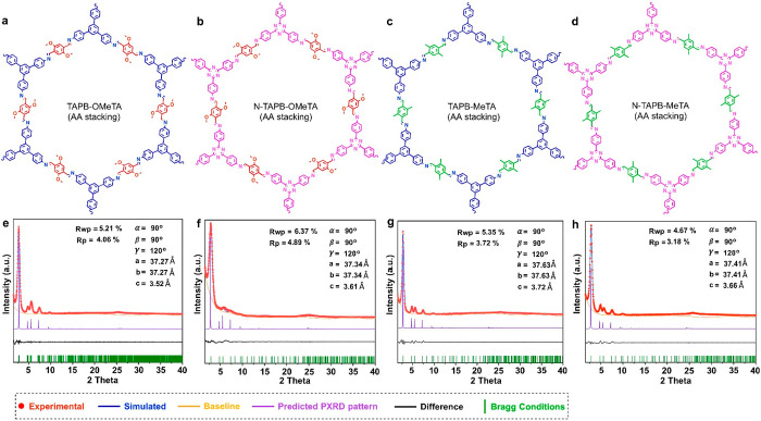
In the present study, we selected four different 2D COFs for the systematic study of their aggregated structures. These COFs include one previously reported 2D COF, TAPB-OMeTA,32,34 and three new 2D COFs, namely, N-TAPB-OMeTA, TAPB-MeTA, and N-TAPB-MeTA (Figure 1a–d). TAPB-OMeTA was synthesized by Schiff-base condensation between 1,3,5-tris(4-aminophenyl)benzene (TAPB) and 2,5-dimethoxy terephthalaldehyde (OMeTA), N-TAPB-OMeTA was synthesized by the reaction between 4,4′,4′′-(1,3,5-triazine-2,4,6-triyl)trianiline (N-TAPB) and OMeTA, TAPB-MeTA was synthesized by the reaction of TAPB and 2,5-dimethylterephthalaldehyde (MeTA), and N-TAPB-MeTA was synthesized by the Schiff-base reaction between N-TAPB and MeTA. (Refer to the Supporting Information for detailed synthesis procedures, Figures S1–S9.) PXRD measurements show that all four have good crystallinity. Computer simulation and Pawley refinements indicate that all adopt AA stacking structures (Figure 1e–h, Tables S1–S3). These COFs were selected because they are representative examples of the most widely studied category of COFs—those having Schiff-base linkages.35 More importantly, the methoxy and methyl side groups on these COF backbones have very different NMR chemical shifts compared with other nuclei in the COF structures, facilitating data processing. Additionally, N-TAPB-OMeTA and N-TAPB-MeTA were selected because in addition to their side groups, the carbon atoms in the triazine structure also have very different NMR chemical shifts compared with other nuclei in the COF backbone, providing an additional probe to detect the chemical environment experienced by the backbone. Additional information about the aggregated structures of 2D COFs can be obtained by comparing chemical environment differences between carbon atoms in side groups and carbon atoms in the COF backbone
Figure 1.
Chosen 2D COFs for the 13C SSNMR study. Chemical structures of (a) TAPB-OMeTA, (b) N-TAPB-OMeTA, (c) TAPB-MeTA, and (d) N-TAPB-MeTA. PXRD patterns and Pawley refinements of (e) TAPB-OMeTA, (f) N-TAPB-OMeTA, (g) TAPB-MeTA, and (h) N-TAPB-MeTA.
Feasibility of 13C SSNMR
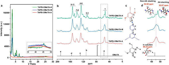
The feasibility of 13C SSNMR to distinguish different aggregated structures in a 2D COF was initially tested using TAPB-OMeTA with different crystallinities as an example. TABP-OMeTA was selected for its general high crystallinity, allowing us to tune the crystallinity over a wide range. By controlling the COF growth time, we prepared TAPB-OMeTA samples with middle crystallinity (TABP-OMeTA-M) and high crystallinity (TAPB-OMeTA-H). However, TAPB-OMeTA crystallized too fast to obtain an amorphous sample by controlling only the growth time. Instead, we obtained the amorphous TABP-OMeTA (TABP-OMeTA-A) starting from the frozen state followed by polymerization at room temperature. (Refer to the Supporting Information for detailed synthetic procedures.) Each sample was characterized by PXRD (Figure 2a). To quantify PXRD data and avoid possible differences caused by sample preparation,36 we pressed 15.0 mg of each sample with 5 kN force to form a round flake of 1.0 cm in diameter. All COF samples in the present study were measured on the same PXRD instrument without baseline subtraction. The results are shown in Figure 2a, from which we can see that TAPB-OMeTA-H has sharp peaks with the highest signal intensity (Figure 2a (green)). TAPB-OMeTA-M also has sharp peaks, but its signal intensity is much lower than that of TAPB-OMeTA-H (Figure 2a (blue)). No PXRD signal from the crystalline phase can be detected in TAPB-OMeTA-A (Figure 2a (red)). These samples were then characterized by N2 sorption (Figure S10), giving TAPB-OMeTA-A, -M, and -H SBET values of 98.5, 672.6, and 2535.2 cm2/g, respectively. These are consistent with the crystallinity trend shown by PXRD (Figure 2a). TAPB-OMeTA-A has no regular pores; its SBET value of 98.5 cm2/g may be attributed to N2 adsorption on external particle surfaces.
Figure 2.
Characterization of TAPB-OMeTA with different crystallinities. (a) PXRD patterns. (b) 13C SSNMR spectra of TAPB-OMeTA, *CDCl3. (c) Attribution of NMR signals to TAPB-OMeTA and OMeTA chemical structures. (d) Magnified 13C SSNMR signal of methoxy group in panel b.
Subsequently, TAPB-OMeTA samples with different crystallinities were characterized by 13SSNMR (Figure 2b–d). From the 13C SSNMR signal assignment (Figure 2c), we can see that most carbon atoms in COFs have chemical shifts ranging from 100 to 160 ppm. Their signals interfere with each other, which prevents us from analyzing their chemical environment. Fortunately, the chemical shift of the carbon nucleus in the methoxy group is located at ∼55 ppm without interfering with other nuclei; therefore, the methoxy group can be used as a probe to study the aggregated structures of TAPB-OMeTA. The methoxy carbon in TAPB-OMeTA-A has a chemical shift of 54.92 ppm (Figure 2b,d (red)). However, the signal of the methoxy group in TAPB-OMeTA-M split into two parts (Figure 2b (blue)): One remained at 54.92 ppm, and the other new peak appeared at 52.67 ppm. The relatively low intensity of this new peak increased significantly in TAPB-OMeTA-H (Figure 2b,d (green)). From these data, we can see that the intensity of the 52.67 ppm peak is consistent with the crystallinity trend of TAPB-OMeTA.
The different chemical shifts of methoxy groups in TAPB-OMeTA-H indicate that these methoxy groups located in different chemical environments, which were created by different aggregated structures. Specifically, as for TAPB-OMeTA-A, only one methoxy signal (54.92 ppm) was detected, which means that all of the methoxy groups in noncrystalline or non-AA stacking structures share similar chemical environments. As for TAPB-OMeTA-H, its high crystallinity clearly changes the chemical environments of the methoxy groups so that the new signal at 52.67 ppm can be attributed to the methoxy groups in the crystalline structure, which is also an AA-stacking structure proved by PXRD and Pawley refinements. The appearance of both signals at 54.92 and 52.67 ppm in TAPB-OMeTA-H implies the coexistence of AA and non-AA stacking structures. Notably, the methoxy groups in non-AA stacking structures cannot generate the signal at 52.67 ppm, as indicated by the 13C SSNMR spectrum of TAPB-OMeTA-A. Therefore, the signal at 52.67 ppm can be exclusively attributed to the methoxy groups in AA stacking structures. From this perspective, 13C SSNMR is especially good at distinguishing the AA stacking structure from other aggregated structures.
The reason that methoxy groups in the AA stacking structure have a smaller chemical shift (52.67 ppm) than the methoxy groups in the non-AA stacking structure (54.92 ppm) can be explained as follows: In the AA stacking structure, the distance between adjacent layers is 3.5 Å;32 under such a confined space, the methoxy groups from adjacent COF layers can interact intimately with each other. Such a special chemical environment cannot be created by non-AA stacking structures. Intimate interaction increases the electron density that surrounds and shields the carbon nuclei of methoxy groups, which moves the magnetic resonant frequency to upfield with a smaller chemical shift value. A more general conclusion is that spatial confinement and an intimate interaction between adjacent 2D COF layers move chemical shifts to smaller values. This conclusion is further confirmed by the observation that without any intimate interactions, the methoxy groups of a freely moving OMeTA monomer in CDCl3 solution have the largest chemical shift value of 56.22 ppm (Figure 2b,d (black)). On the basis of the above results, we conclude that 13C SSNMR can distinguish different aggregated structures in a 2D COF.
It should be pointed out that the methoxy group was selected as an indicator of the 2D COF interlayer interaction because its chemical shift is different from that of other nuclei, facilitating data processing. The majority of COF carbon nuclei, such as those in phenyl groups, generally have similar chemical shift values. Therefore, several nuclei may share one combined signal in the 13C SSNMR spectrum. It is interesting to observe that such a combined 13C SSNMR signal could also have a signal splitting phenomenon. For example, carbon nuclei 9–11 (Figure 2b) have a combined signal at 152.9 ppm in TAPB-OMeTA-A. This combined peak split into two peaks when the COF crystallinity increased, resulting in an additional peak at 146.8 ppm in TAPB-OMeTA-H. However, it is challenging to quantify the contribution of each nucleus for the newly emerged signal; therefore, only those nuclei that have independent 13C SSNMR signals are used to study 2D COF aggregated structures in the present study.
13C SSNMR Study on Other 2D COFs
Next, 13C SSNMR was applied to analyze the aggregated structures of N-TAPB-OMeTA, TAPB-MeTA, and N-TAPB-MeTA (Figure 3). Specifically, N-TAPB-OMeTA was selected to examine if the signal splitting phenomenon could be observed for methoxy groups in other 2D COFs. From Figure 3b, we can see that signal splitting can be observed for methoxy groups in N-TAPB-OMeTA. One sharp signal locates at 52.55 ppm, similar to that of the methoxy groups in the AA stacking structure of TAPB-OMeTA (52.67 ppm). We attribute this signal at 52.55 ppm to the methoxy groups in the AA stacking structure of N-TAPB-OMeTA. The other signal at 53.93 ppm is attributed to the methoxy groups in non-AA stacking structures.
Figure 3.
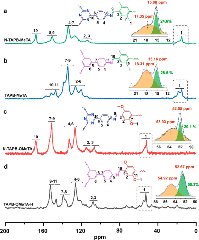
13C SSNMR spectrum, signal assignment, and methyl group signal area calculation of (a) N-TAPB-MeTA, (b) TAPB-MeTA, (c) N-TAPB-OMeTA, and (d) TAPB-OMeTA-H.
TAPB-MeTA and N-TAPB-MeTA were selected to test if, in addition to methoxy groups, other side groups would have a signal-splitting phenomenon in 13C SSNMR spectra. From Figure 3b, we can see that the signal of the methyl group in TAPB-MeTA split into two parts, one located at 15.16 ppm and the other at 18.31 ppm. As an analog to the methoxy groups in which carbon nuclei in the AA-stacking structure have smaller chemical shifts because of their intimate interaction, which increases the electron density and surrounds and shields the carbon nuclei, the sharp signal at 15.16 ppm is attributed to the intimately interacting methyl groups in the AA stacking structure. In comparison, the peak at 18.31 ppm is due to the methyl groups without intimate interactions, and they locate in non-AA stacking structures. As a reference, methyl groups without any close interaction in the solution-dissolved MeTA monomer have a chemical shift of 18.86 ppm (Figure S11). As for N-TAPB-MeTA, signal splitting of its methyl groups was also observed in the 13C SSNMR spectrum, in which the sharp peak at 15.08 ppm is attributed to the intimately interacting methyl groups in the AA stacking structure and the other signal at 17.35 ppm is assigned to the nonintimately interacting methyl groups in non-AA stacking structures.
Quantification of AA Stacking Structure
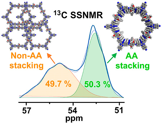
Quantifying the amount of AA stacking structure in a 2D COF is especially important because the AA stacking structure is the most frequently reported crystalline structure in 2D COFs. However, to the best of our knowledge, quantitative calculation of AA stacking structures has not yet been achieved. On the basis of the above 13C SSNMR data, the percentage of AA stacking structure can be calculated by counting the number of carbon atoms located in the AA stacking structure and comparing this value with the number of carbon atoms located in non-AA stacking structures. Because of a certain degree of overlap between 13C SSNMR signals, a Gaussian function was applied to calculate the signal areas of side groups from AA or non-AA stacking structures. The results are shown in Figure 3, from which we can see that TAPB-OMeTA-H has the highest AA stacking structure content of 50.3%. This value is 20.1, 28.5, and 24.6% for N-TAPB-OMeTA, TABP-MeTA, and N-TAPB-MeTA, respectively. These data suggest that the AA stacking structure amount is not very high for the latter three COFs, despite their sharp PXRD peaks.
Offset Stacking Structure
The crystalline phase in most 2D COFs has been widely found to be an AA stacking structure, which can be detected by PXRD. Are there other stacking structures potentially present in 2D COFs that do not have periodically ordered arrangements and thus elude X-ray detection?
In the present study, 13C SSNMR data suggest that such stacking structures may exist in 2D COFs. We name these “offset” stacking structures. In addition to methoxy and methyl side groups, the framework triazine carbon atoms in N-TAPB-OMeTA and N-TAPB-MeTA have chemical shifts distinct from those of other nuclei (Figure 4). Therefore, the shifts of these triazine carbon atoms can provide valuable information about their chemical environments. The 13C SSNMR signal of triazine carbon nuclei in N-TAPB-OMeTA splits into two parts: one sharp peak at 167.86 ppm and a broad peak at 170.65 ppm (Figure 4a,b). Similar to signal splitting for methoxy or methyl groups, the peak at 167.86 ppm is attributed to triazine carbon atoms having close interactions, whereas the peak at 170.65 ppm is attributed to the triazine carbon atoms without intimate interactions. As a reference, free triazine carbon atoms in solution-dissolved N-TAPB monomer (without any intimate interlayer interactions) have a chemical shift of 171.02 ppm (Figure S12). After counting the number of the carbon nuclei in these two different chemical environments, we found that closely interacting triazine carbon atoms account for 77.6% of the total, a much higher percentage than that of the intimately interacting carbon nuclei in the methoxy groups of N-TAPB-OMeTA (20.1%). Thus not all of the closely interacting triazine carbon atoms correspond to closely interacting methoxy carbon atoms.
Figure 4.
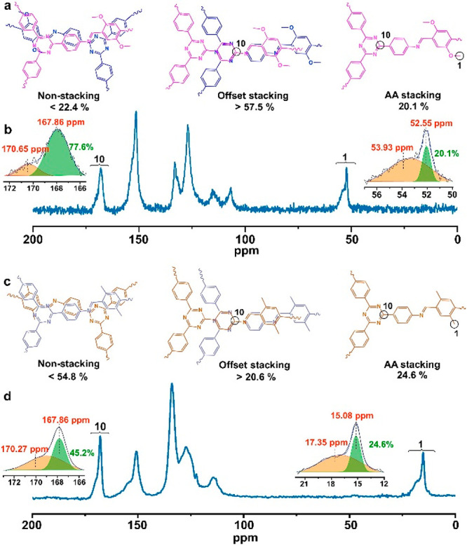
Comparison of chemical environment differences between different carbon atoms from backbones and side groups of 2D COFs. (a) Proposed different aggregated structures in N-TAPB-OMeTA. (b) 13C SSNMR spectrum and signal area calculation of carbon atoms from triazine structure on the COF backbone and the methoxy side group of N-TAPB-OMeTA. (c) Proposed different aggregated structures in N-TAPB-MeTA. (d) 13C SSNMR spectrum and signal area calculation of carbon atoms from triazine structure on the COF backbone and the methyl side group of N-TAPB-MeTA.
In the AA stacking structure, all triazine carbon atoms should have intimate interlayer interactions; these triazine atoms account for 20.1% of the total. Therefore, among the 77.6% intimately interacting triazine carbon atoms, 57.5% are not included in the AA stacking structure. We hypothesize that the extra 57.5% of these triazine carbon atoms are located in a new type of structure, which should have the following features. First, it should be a type of stacking structure because only stacking structures can make this 57.5% of triazine carbon atoms on the N-TAPB-OMeTA backbone closely interact. Second, this new stacking structure has no long-range ordering because it cannot generate sharp diffraction peaks on its PXRD patterns. On the basis of these analyses, we propose the existence of a new type of offset stacking structure in which COF layers are not exactly on top of each other but have certain degrees of random displacement, resulting in no intimate interactions between methoxy side groups. However, in these structures, the triazine carbon atoms still have close interactions with carbon atoms in adjacent layers and have similar chemical shifts to that of the triazine carbon atoms in the AA stacking structure (Figure 2a). In other words, intimately interacting methoxy side groups can only be found in the AA stacking structure. However, intimately interacting triazine groups in the COF backbone can be found in both AA stacking and offset stacking structures, which explains why triazine has a much higher percentage of intimately interacting triazine carbon atoms than methoxy group carbon atoms. It should be noted that in the offset stacking structure model, not all triazine carbon atoms are required to have intimate interactions. Therefore, the offset stacking structure ratio is underestimated by counting only triazine carbon atoms with intimate interactions. Subsequently, the amount of material present in the offset structure should be >57.5% in N-TAPB-OMeTA. There are 22.4% triazine carbon atoms (170.65 ppm) without any intimate interactions, and we attribute these carbon atoms to nonstacking structures in N-TABP-OMeTA.
As an analog to N-TAPB-OMeTA, a similar structural analysis can be performed on N-TAPB-MeTA (Figure 4c,d). The offset stacking structure in N-TAPB-MeTA accounts for >20.6% of the total, which is quite different from what is seen for N-TAPB-OMeTA (>57.5%). Therefore, we conclude that the amount of offset stacking structures present varies with different 2D COFs.
Aggregated Structures in Solution
In addition to the characterization of dried-state 2D COFs by 13C SSNMR, it is necessary to examine aggregated structures of 2D COFs in solution because a significant amount of 2D COF applications take place in solutions,37,38 and solvated 2D COFs may have different aggregated structures compared with their dried counterparts.
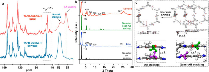
In the present study, highly crystalline TAPB-OMeTA-H was used as an example to study aggregated structures in CDCl3 (Figure 5). Compared with the 13C SSNMR spectrum of the dried state, the AA stacking structure signal (52.67 ppm) disappeared in CDCl3-solvated TAPB-OMeTA-H. In other words, the AA stacking structure does not exist in the solvated TAPB-OMeTA-H (Figure 5a). PXRD measurements indicate that the solvated TAPB-OMeTA-H has good crystallinity, although the pattern of the solvated TAPB-OMeTA-H is different from that of its dried form. We thus conclude that the AA stacking structure in dried TAPB-OMeTA-H transforms into a different crystalline structure when solvated. Computer simulation and Pawley refinements indicate that the solvated TAPB-OMeTA-H adopts a quasi-AB stacking structure (Figure S13, Table S4), which agrees with a previous study.39 In the quasi-AB stacking structure, the distance between methoxy groups of adjacent COF layers increases from 3.5 to 4.8 Å, such that the methoxy groups no longer interact intimately with adjacent COF layers. Therefore, their chemical shifts fall within the range of methoxy groups that do not have intimate interactions (54.92 ppm). In summary, 13C SSNMR demonstrates that 2D COFs have different aggregated structures in dried and solvated states, which means that 2D COF crystal structures determined in the dried state may not be suitable for interpreting the properties 2D COFs when being used in solutions.
Figure 5.
(a) 13C SSNMR spectra of TAPB-OMeTA-H measured in dried and solvated states. (b) Experimental and simulated PXRD patterns of dried and solvated TAPB-OMeTA-H. (c) Scheme of the transformation from AA stacking to quasi-AB stacking structure of TAPB-OMeTA. The structures are obtained from Pawley refinement of the PXRD patterns.
Conclusions
In the present study, we systematically examined the aggregated structures of four 2D COFs, namely, TAPB-OMeTA, N-TAPB-OMeTA, TAPB-MeTA, and N-TAPB-MeTA, using 13C SSNMR techniques. On the basis of the signal splitting phenomenon of methoxy/methyl side groups in 13C SSNMR spectra, AA stacking structures of the studied 2D COFs can be distinguished from non-AA stacking structures. Furthermore, by counting the number of carbon atoms located in both AA and non-AA stacking structures, the AA stacking structure can be quantified for the first time. In a comparison of chemical environments experienced by carbon nuclei between COF side groups and COF backbones, 13C SSNMR data suggest the existence of a previously unknown offset stacking structure. On the basis of these results, the aggregated structures of 2D COFs can be divided into three major categories: AA stacking, offset stacking, and nonstacking structures. Furthermore, 13C SSNMR data indicate that dried and solvated 2D COFs have different aggregated structures. The AA stacking structure in the dried state transforms into a quasi-AB stacking structure in the solvated state. It should be noted that the essence of the 13C SSNMR method for studying COF aggregated structures is that different stacking styles result in different interactions between atoms/groups from adjacent COF interlayers. This principle may also be applied to other 2D COF systems with AB or ABC stacking modes. In summary, our results indicate that it is possible to quantitatively characterize the aggregated structures of polycrystalline 2D COFs. A better understanding of 2D COF structures helps clarify structure–performance relationships, providing valuable information for the design, synthesis, and evaluation of 2D COFs for different purposes and enabling their wide and efficient applications.
Acknowledgments
This work was supported by ExxonMobil through the Singapore Energy Center, the National Research Foundation Singapore (NRF2018-NRF-ANR007 POCEMON), and the Ministry of Education-Singapore (MOE2018-T2-2-148, MOE2019-T2-1-093).
Supporting Information Available
The Supporting Information is available free of charge at https://pubs.acs.org/doi/10.1021/jacs.1c12708.
Experimental details and materials, synthesis of COFs, structure characterization, simulation, and 13C SSNMR measurements (PDF)
The authors declare no competing financial interest.
Supplementary Material
References
- Côté A. P.; Benin A. I.; Ockwig N. W.; O’Keeffe M.; Matzger A. J.; Yaghi O. M. Porous, Crystalline, Covalent Organic Frameworks. Science 2005, 310 (5751), 1166–1170. 10.1126/science.1120411. [DOI] [PubMed] [Google Scholar]
- Li J.; Jing X.; Li Q.; Li S.; Gao X.; Feng X.; Wang B. Bulk COFs and COF Nanosheets for Electrochemical Energy Storage and Conversion. Chem. Soc. Rev. 2020, 49 (11), 3565–3604. 10.1039/D0CS00017E. [DOI] [PubMed] [Google Scholar]
- Xu F.; Yang S.; Chen X.; Liu Q.; Li H.; Wang H.; Wei B.; Jiang D. Energy-Storage Covalent Organic Frameworks: Improving Performance via Engineering Polysulfide Chains on Walls. Chem. Sci. 2019, 10 (23), 6001–6006. 10.1039/C8SC04518F. [DOI] [PMC free article] [PubMed] [Google Scholar]
- Vitaku E.; Gannett C. N.; Carpenter K. L.; Shen L.; Abruña H. D.; Dichtel W. R. Phenazine-Based Covalent Organic Framework Cathode Materials with High Energy and Power Densities. J. Am. Chem. Soc. 2020, 142 (1), 16–20. 10.1021/jacs.9b08147. [DOI] [PubMed] [Google Scholar]
- Fan H.; Mundstock A.; Feldhoff A.; Knebel A.; Gu J.; Meng H.; Caro J. Covalent Organic Framework-Covalent Organic Framework Bilayer Membranes for Highly Selective Gas Separation. J. Am. Chem. Soc. 2018, 140 (32), 10094–10098. 10.1021/jacs.8b05136. [DOI] [PubMed] [Google Scholar]
- Han S. S.; Furukawa H.; Yaghi O. M.; Goddard W. A. Covalent Organic Frameworks as Exceptional Hydrogen Storage Materials. J. Am. Chem. Soc. 2008, 130 (35), 11580–11581. 10.1021/ja803247y. [DOI] [PubMed] [Google Scholar]
- Liu X.; Huang D.; Lai C.; Zeng G.; Qin L.; Wang H.; Yi H.; Li B.; Liu S.; Zhang M.; Deng R.; Fu Y.; Li L.; Xue W.; Chen S. Recent Advances in Covalent Organic Frameworks (COFs) as a Smart Sensing Material. Chem. Soc. Rev. 2019, 48 (20), 5266–5302. 10.1039/C9CS00299E. [DOI] [PubMed] [Google Scholar]
- Ascherl L.; Evans E. W.; Hennemann M.; Di Nuzzo D.; Hufnagel A. G.; Beetz M.; Friend R. H.; Clark T.; Bein T.; Auras F. Solvatochromic Covalent Organic Frameworks. Nat. Commun. 2018, 9 (1), 1–8. 10.1038/s41467-018-06161-w. [DOI] [PMC free article] [PubMed] [Google Scholar]
- Ascherl L.; Evans E. W.; Gorman J.; Orsborne S.; Bessinger D.; Bein T.; Friend R. H.; Auras F. Perylene-Based Covalent Organic Frameworks for Acid Vapor Sensing. J. Am. Chem. Soc. 2019, 141 (39), 15693–15699. 10.1021/jacs.9b08079. [DOI] [PubMed] [Google Scholar]
- Ding S.-Y.; Dong M.; Wang Y.-W.; Chen Y.-T.; Wang H.-Z.; Su C.-Y.; Wang W. Thioether-Based Fluorescent Covalent Organic Framework for Selective Detection and Facile Removal of Mercury(II). J. Am. Chem. Soc. 2016, 138 (9), 3031–3037. 10.1021/jacs.5b10754. [DOI] [PubMed] [Google Scholar]
- Bai L.; Phua S. Z. F.; Lim W. Q.; Jana A.; Luo Z.; Tham H. P.; Zhao L.; Gao Q.; Zhao Y. Nanoscale Covalent Organic Frameworks as Smart Carriers for Drug Delivery. Chem. Commun. 2016, 52 (22), 4128–4131. 10.1039/C6CC00853D. [DOI] [PubMed] [Google Scholar]
- Li M.; Qiao S.; Zheng Y.; Andaloussi Y. H.; Li X.; Zhang Z.; Li A.; Cheng P.; Ma S.; Chen Y. Fabricating Covalent Organic Framework Capsules with Commodious Microenvironment for Enzymes. J. Am. Chem. Soc. 2020, 142 (14), 6675–6681. 10.1021/jacs.0c00285. [DOI] [PubMed] [Google Scholar]
- Guo J.; Jiang D. Covalent Organic Frameworks for Heterogeneous Catalysis: Principle, Current Status, and Challenges. ACS Cent. Sci. 2020, 6 (6), 869–879. 10.1021/acscentsci.0c00463. [DOI] [PMC free article] [PubMed] [Google Scholar]
- Ding S.-Y.; Gao J.; Wang Q.; Zhang Y.; Song W.-G.; Su C.-Y.; Wang W. Construction of Covalent Organic Framework for Catalysis: Pd/COF-LZU1 in Suzuki-Miyaura Coupling Reaction. J. Am. Chem. Soc. 2011, 133 (49), 19816–19822. 10.1021/ja206846p. [DOI] [PubMed] [Google Scholar]
- Sharma R. K.; Yadav P.; Yadav M.; Gupta R.; Rana P.; Srivastava A.; Zbořil R.; Varma R. S.; Antonietti M.; Gawande M. B. Recent Development of Covalent Organic Frameworks (COFs): Synthesis and Catalytic (Organic-Electro-Photo) Applications. Mater. Horiz. 2020, 7 (2), 411–454. 10.1039/C9MH00856J. [DOI] [Google Scholar]
- Wang J.; Zhuang S. Covalent Organic Frameworks (COFs) for Environmental Applications. Coord. Chem. Rev. 2019, 400, 213046. 10.1016/j.ccr.2019.213046. [DOI] [Google Scholar]
- Nguyen H. L.; Hanikel N.; Lyle S. J.; Zhu C.; Proserpio D. M.; Yaghi O. M. A Porous Covalent Organic Framework with Voided Square Grid Topology for Atmospheric Water Harvesting. J. Am. Chem. Soc. 2020, 142 (5), 2218–2221. 10.1021/jacs.9b13094. [DOI] [PubMed] [Google Scholar]
- Yuan S.; Li X.; Zhu J.; Zhang G.; Van Puyvelde P.; Van der Bruggen B. Covalent Organic Frameworks for Membrane Separation. Chem. Soc. Rev. 2019, 48 (10), 2665–2681. 10.1039/C8CS00919H. [DOI] [PubMed] [Google Scholar]
- Ding S.-Y.; Wang W. Covalent Organic Frameworks (COFs): From Design to Applications. Chem. Soc. Rev. 2013, 42 (2), 548–568. 10.1039/C2CS35072F. [DOI] [PubMed] [Google Scholar]
- Diercks C. S.; Yaghi O. M. The Atom, the Molecule, and the Covalent Organic Framework. Science 2017, 355 (6328), eaal1585 10.1126/science.aal1585. [DOI] [PubMed] [Google Scholar]
- Jin E.; Asada M.; Xu Q.; Dalapati S.; Addicoat M. A.; Brady M. A.; Xu H.; Nakamura T.; Heine T.; Chen Q.; Jiang D. Two-Dimensional Sp2 Carbon-Conjugated Covalent Organic Frameworks. Science 2017, 357 (6352), 673–676. 10.1126/science.aan0202. [DOI] [PubMed] [Google Scholar]
- Liang R.-R.; Xu S.-Q.; Zhang L.; A R.-H.; Chen P.; Cui F.-Z.; Qi Q.-Y.; Sun J.; Zhao X. Rational Design of Crystalline Two-Dimensional Frameworks with Highly Complicated Topological Structures. Nat. Commun. 2019, 10 (1), 4609. 10.1038/s41467-019-12596-6. [DOI] [PMC free article] [PubMed] [Google Scholar]
- Ma T.; Kapustin E. A.; Yin S. X.; Liang L.; Zhou Z.; Niu J.; Li L.-H.; Wang Y.; Su J.; Li J.; Wang X.; Wang W. D.; Wang W.; Sun J.; Yaghi O. M. Single-Crystal x-Ray Diffraction Structures of Covalent Organic Frameworks. Science 2018, 361 (6397), 48–52. 10.1126/science.aat7679. [DOI] [PubMed] [Google Scholar]
- Evans A. M.; Parent L. R.; Flanders N. C.; Bisbey R. P.; Vitaku E.; Kirschner M. S.; Schaller R. D.; Chen L. X.; Gianneschi N. C.; Dichtel W. R. Seeded Growth of Single-Crystal Two-Dimensional Covalent Organic Frameworks. Science 2018, 361 (6397), 52–57. 10.1126/science.aar7883. [DOI] [PubMed] [Google Scholar]
- Gropp C.; Ma T.; Hanikel N.; Yaghi O. M. Design of Higher Valency in Covalent Organic Frameworks. Science 2020, 370 (6515), eabd6406 10.1126/science.abd6406. [DOI] [PubMed] [Google Scholar]
- Liang L.; Qiu Y.; Wang W. D.; Han J.; Luo Y.; Yu W.; Yin G.-L.; Wang Z.-P.; Zhang L.; Ni J.; Niu J.; Sun J.; Ma T.; Wang W. Non-Interpenetrated Single-Crystal Covalent Organic Frameworks. Angew. Chem., Int. Ed. 2020, 59 (41), 17991–17995. 10.1002/anie.202007230. [DOI] [PubMed] [Google Scholar]
- Smith B. J.; Overholts A. C.; Hwang N.; Dichtel W. R. Insight into the Crystallization of Amorphous Imine-Linked Polymer Networks to 2D Covalent Organic Frameworks. Chem. Commun. 2016, 52 (18), 3690–3693. 10.1039/C5CC10221A. [DOI] [PubMed] [Google Scholar]
- Wu X.; Han X.; Liu Y.; Liu Y.; Cui Y. Control Interlayer Stacking and Chemical Stability of Two-Dimensional Covalent Organic Frameworks via Steric Tuning. J. Am. Chem. Soc. 2018, 140 (47), 16124–16133. 10.1021/jacs.8b08452. [DOI] [PubMed] [Google Scholar]
- Du Y.; Calabro D.; Wooler B.; Li Q.; Cundy S.; Kamakoti P.; Colmyer D.; Mao K.; Ravikovitch P. Kinetic and Mechanistic Study of COF-1 Phase Change from a Staggered to Eclipsed Model upon Partial Removal of Mesitylene. J. Phys. Chem. C 2014, 118 (1), 399–407. 10.1021/jp4097293. [DOI] [Google Scholar]
- Hao Q.; Li Z.-J.; Lu C.; Sun B.; Zhong Y.-W.; Wan L.-J.; Wang D. Oriented Two-Dimensional Covalent Organic Framework Films for Near-Infrared Electrochromic Application. J. Am. Chem. Soc. 2019, 141 (50), 19831–19838. 10.1021/jacs.9b09956. [DOI] [PubMed] [Google Scholar]
- Kuehl V. A.; Yin J.; Duong P. H. H.; Mastorovich B.; Newell B.; Li-Oakey K. D.; Parkinson B. A.; Hoberg J. O. A Highly Ordered Nanoporous, Two-Dimensional Covalent Organic Framework with Modifiable Pores, and Its Application in Water Purification and Ion Sieving. J. Am. Chem. Soc. 2018, 140 (51), 18200–18207. 10.1021/jacs.8b11482. [DOI] [PubMed] [Google Scholar]
- Xu H.; Gao J.; Jiang D. Stable, Crystalline, Porous, Covalent Organic Frameworks as a Platform for Chiral Organocatalysts. Nat. Chem. 2015, 7 (11), 905–912. 10.1038/nchem.2352. [DOI] [PubMed] [Google Scholar]
- Forse A. C.; Griffin J. M.; Merlet C.; Bayley P. M.; Wang H.; Simon P.; Grey C. P. NMR Study of Ion Dynamics and Charge Storage in Ionic Liquid Supercapacitors. J. Am. Chem. Soc. 2015, 137 (22), 7231–7242. 10.1021/jacs.5b03958. [DOI] [PMC free article] [PubMed] [Google Scholar]
- Feriante C. H.; Jhulki S.; Evans A. M.; Dasari R. R.; Slicker K.; Dichtel W. R.; Marder S. R. Rapid Synthesis of High Surface Area Imine-Linked 2D Covalent Organic Frameworks by Avoiding Pore Collapse During Isolation. Adv. Mater. 2020, 32 (2), 1905776. 10.1002/adma.201905776. [DOI] [PubMed] [Google Scholar]
- Segura J. L.; Mancheño M. J.; Zamora F. Covalent Organic Frameworks Based on Schiff-Base Chemistry: Synthesis, Properties and Potential Applications. Chem. Soc. Rev. 2016, 45 (20), 5635–5671. 10.1039/C5CS00878F. [DOI] [PubMed] [Google Scholar]
- Vazquez-Molina D. A.; Mohammad-Pour G. S.; Lee C.; Logan M. W.; Duan X.; Harper J. K.; Uribe-Romo F. J. Mechanically Shaped Two-Dimensional Covalent Organic Frameworks Reveal Crystallographic Alignment and Fast Li-Ion Conductivity. J. Am. Chem. Soc. 2016, 138 (31), 9767–9770. 10.1021/jacs.6b05568. [DOI] [PubMed] [Google Scholar]
- Shinde D. B.; Sheng G.; Li X.; Ostwal M.; Emwas A.-H.; Huang K.-W.; Lai Z. Crystalline 2D Covalent Organic Framework Membranes for High-Flux Organic Solvent Nanofiltration. J. Am. Chem. Soc. 2018, 140 (43), 14342–14349. 10.1021/jacs.8b08788. [DOI] [PubMed] [Google Scholar]
- Song Y.; Sun Q.; Aguila B.; Ma S. Opportunities of Covalent Organic Frameworks for Advanced Applications. Adv. Sci. 2019, 6 (2), 1801410. 10.1002/advs.201801410. [DOI] [PMC free article] [PubMed] [Google Scholar]
- Kang C.; Zhang Z.; Wee V.; Usadi A. K.; Calabro D. C.; Baugh L. S.; Wang S.; Wang Y.; Zhao D. Interlayer Shifting in Two-Dimensional Covalent Organic Frameworks. J. Am. Chem. Soc. 2020, 142 (30), 12995–13002. 10.1021/jacs.0c03691. [DOI] [PubMed] [Google Scholar]
Associated Data
This section collects any data citations, data availability statements, or supplementary materials included in this article.


