

Abstract

The wall effects on the sedimentation motion of a single spheroidal particle in cylindrical tubes filled with Bingham plastic fluid are investigated with the fixed computational domain using the Computational Fluid Dynamic (CFD) model in steady-state mode. The CFD model is validated with literature in both bounded and unbounded mediums. The rheological model of the Bingham plastic fluid is regularized with a smoothly varying viscosity. The retardation effects of the tube wall are presented in functions of Reynolds number Re, radius ratio λ (the radius of the tube to the semiaxis of the particle normal to the flow λ = R/r), aspect ratio E (the ratio of the semiaxis of the particle along the flow to r, E = b/r), and Bingham number Bn. The simulation results demonstrate that the drag coefficient CD declines with the rise in Reynolds number. The relative contribution to drag coefficient from the pressure force increases with larger Bingham number comparing with that from the friction force. The formation and size of the recirculation wake is suppressed by the yield stress. While Bn is approaching infinity, the limiting behavior is observed in the location of yield surface and the value of yield-gravity parameter. The values of critical yield-gravity parameter are explicitly given at different values of E, showing independence with Re and λ. For the flow with Bn ≥ 100, the influence of wall can be even ignored while λ is larger than 5.
1. Introduction
The sedimentation motion of a particle in liquid or flow past a rigid body is a research topic of interest in fluid mechanics, considering its widespread applications in solid–liquid separator, movement of particles in slurry, viscometer, fluid-bed, etc.1−3 For over a century, studies have been extended from the simplest case of a single sphere in Newtonian rheology, which was first investigated by Stokes,4 to more complex cases, including surrounding fluid in an unsteady motion state5,6 or of non-Newtonian rheology, different shapes of particle (e.g., disc, cylinder cone,7 and spheroid8,9) and multiparticle systems.3,10 By virtue of the yield stress, the visco-plastic material exhibits a very important characteristic. When the shear stress is below the yield value, the fluid does not deform and acts as a rigid solid. Ideally, for a rheology without yield stress, the flow is sheared everywhere, even in an infinite medium in the problem of flow past rigid body. However, under the condition of yield stress, the unsheared region(s) is formed in the flow and separated from the sheared region(s) by distinct yield surface(s). In a limiting case, while the shear stress imposed by the particle is not enough to overcome the yield stress, no sheared region exists in the flow and the fluid sustains the applied stress in a stationary condition. This condition is referred as static equilibrium in the literature, and the criterion used for the establishment of equilibrium condition is often expressed by the critical value of yield-gravity parameter, Yg.11 Usually, the drag coefficient CD and the value of critical Yg are the focus of concern in those studies on the fluid–particle system with visco-plastic mediums.
The literature shows that work has been conducted to disclose the standard drag curve and critical Yg of a spherical particle with infinite Bingham plastic fluids. Volarovich and Gutkin12 first raised the point that the visco-plastic rheology behaved as a fluid in a small envelope, which was surrounding the particle, and no shear but elastic force occurred outside the envelope. By assuming the envelope of a spherical shape to be concentric with the particle, Valentik and Whitmore13 measured the terminal velocity of the falling particle and estimated the diameter of the envelope using a modified model based on Newtonian fluids. Subsequently, Ansley and Smith14 proposed the envelope to be of ‘truncated toroidal shape’ based on the slip-line field theory and correlated the drag coefficient with the Reynolds number. The critical Yg given by them was 0.183–0.255. In 1971, Yoshioka et al.15 predicted two small stationary regions before and after the particle, and the upper and lower bounds on CD were obtained based on the variational principle. Their upper bound results agreed very well with the following numerical work, in which, Beris et al.16 treated the discontinuous equation of Bingham fluids with a regularization approach as proposed by Bercovier and Engelman.17 They calculated the drag coefficient under the creeping flow condition and worked out the critical Yg = 0.143 using the finite-element method. The results of Beris et al.16 were believed to be the most reliable values of CD and critical Yg for the Bingham rheologies in the creeping flow regime because of the great agreement with subsequent numerical6,18,19 and experimental studies.20 Based on the work of Ansley and Smith,14 a crude expression of the maximum value of Reynolds number, beyond which the creeping flow started to develop to noncreeping flow, was given by Chhabra and Uhlherr.21 Machač et al.22 presented new experimental data on the terminal velocity of a falling particle beyond the creeping flow region and evaluated the suitability of available equations for the drag coefficient with modified Reynolds number up to 1000. In 2003, Wilson et al.23 developed an approach to predicting the terminal velocity in non-Newtonian fluids based on equivalent Newtonian fluids of the same viscosity. Their work was recently improved by Arabi and Sanders,24 and a better accuracy of prediction on the terminal velocity could be achieved in the Newton’s regime.
Besides the experiments with a spherical particle, the case with a spheroidal particle also received much attention from researchers. For a Newtonian fluid, based on the analytical methods (e.g., series truncation and Fourier expansion method), the drag phenomena were studied by extending the solutions for spherical particle to spheroids for the flow under the condition of small Reynolds numbers.25,26 Later, numerical methods were employed by Rimon and Lugt27 as well as Pitter et al. to extend the flow regime to those of Re up to 100.28 In their works, drag coefficient was presented in functions of Reynolds number and aspect ratio for the flow with oblate spheroids of E = 0.05 to 0.5. For the non-Newtonian rheologies, the flow past spherical particles in unconfined medium was investigated numerically in the intermediate range of Reynolds numbers up to 100 and for aspect ratios from 0.2 to 5 with shear thinning rheologies by Tripathi et al.,9 shear thickening rheologies by Tripathi and Chhabra,29 and Bingham plastic fluids with Bn up to 100 by Gupta and Chhabra,30 respectively.
Compared to the unbounded fluids in theoretical research, the practical engineering problems are always dealt with in finite-size containers. The motion of a particle is retarded in the presence of a confining wall, namely, CD rises in comparison with that in the unbounded fluids. In view of a cylindrical tube with the spherical particle falling along the axis, the retardation effect of the wall is due to the flow in the negative direction to the movement of particle. In 1990, Atapattu et al.31 concluded that the wall effects existed only if the boundary intersected with the sheared region and worked out the critical diameter ratio by measuring the terminal velocity of a falling particle. Later, Blackery and Mitsoulis19 modified the Bingham plastic equation using an exponential regularization method, which was proposed by Papanastasiou,32 and numerically studied the wall effects for Bingham fluids under creeping flow conditions. Their predicted CD was proven to be within a ∼10% error in a later study by Liu et al.18 A more comprehensive review can be found elsewhere.11,33 Based on the review above, it can be found that the investigation on the wall effects for a spheroidal particle in confined Bingham plastic fluids is still missing. Therefore, the aim of this study is to fill this gap. The flow condition considered here is E = 0.2–5, λ = 2–15, Bn = 0.001–1000 and Re = 0.001–200.
2. Theory
2.1. Rheological Model
In this study, we assume that the fluids are incompressible with unchanging density of ρF and rheologically time-independent. The non-Newtonian Bingham plastic model can be described by eq 1:
| 1 |
where τ̃ is the stress tensor, η̃ is
the apparent viscosity, and  is the rate-of-strain tensor. For Bingham
plastic fluid,
is the rate-of-strain tensor. For Bingham
plastic fluid,  . Here, μB is the Bingham viscosity, τ0 is the yield stress, and
  .
.
The Bingham model suffers from discontinuity
and its implementation poses difficulties in numerical modeling, i.e.,  tends to be zero and apparent viscosity η̃ (
 ) tends to be infinity while the yield surface
is approached.18 Usually, therefore, other
strategies are employed to circumvent this problem caused by the yield
stress.34 One of the popular methods, which
is widely employed for the visco-plastic fluid problem studied here,16,34 is to represent the Bingham model using a smoothly changing viscosity,
which was developed by Bercovier and Engelman,17 as
) tends to be infinity while the yield surface
is approached.18 Usually, therefore, other
strategies are employed to circumvent this problem caused by the yield
stress.34 One of the popular methods, which
is widely employed for the visco-plastic fluid problem studied here,16,34 is to represent the Bingham model using a smoothly changing viscosity,
which was developed by Bercovier and Engelman,17 as
| 2 |
where P is a very small value and has the dimension of inverse time. When P tends to be zero, the ideal Bingham plastic fluid model is recovered from eq2 (as depicted in Figure 1).
Figure 1.

Qualitative illustration of ideal and regularized Bingham plastic model.
The dimensionless form of eq 2 can be achieved by nondimensionalizing the viscosity with μB, velocity gradient with V/d and stress with μBV/d (where V is the relative velocity between particle and tube) as
| 3 |
where Bn is defined as  and
and  .
.
2.2. Reynolds Number
For a spheroidal particle in Bingham fluids, the Reynolds number can be calculated by
| 4 |
where d is the axis of the particle normal to the flow.
2.3. Drag Coefficient
In this study, the semiaxis normal to the flow, i.e., r is chosen as the characterized radius. Thus, the drag coefficient, CD can be given by
| 5 |
where FD is the drag force exerting on the particle. The drag correction factor Y is thus given by
| 6 |
The yield-gravity parameter can be worked out by
| 7 |
2.4. Yield Surface
At the yield surface, the shear stress is equivalent to the yield stress and the following equation is formed:
| 8 |
The shear rate at the yield surface, γ̇Y can be solved from eq 8 as
| 9 |
2.5. Governing Equations
In this study, the governing transport equations, which are continuity and momentum equations, can be expressed in their general forms,35 as
| 10 |
| 11 |
where p is the fluid pressure and U is the velocity field.
3. CFD Simulations
The commercial software program, ANSYS Workbench 17.2, is applied to conduct the simulations. The flow geometries are produced and meshed using the software ICEM, and the flow is specified, solved, and postprocessed utilizing CFX 17.0. The initial geometries are a group of straight tubes with different diameters, combining with one spheroidal particle of E = 0.2–5 symmetrically placed at the tube center. Based on the axisymmetric configuration, the initial geometries are simplified to a quasi-two-dimensional model, obtained by sweeping 1° with a 2D mesh. As shown in Figure 2, the simplified geometry involves five boundaries: inlet, outlet, symmetry, tube wall, and particle wall. In order to eliminate the inlet and outlet boundary effects, the entrance length, Lin and exit length, Lout are selected as Lin = Lout = 100r – b.
Figure 2.
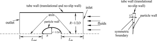
Schematic representation of simplified model with boundary conditions.
In this study, the geometries are meshed using hexahedral cells. A mesh-independence study is carried out to optimize the mesh size for reliable results, meanwhile keeping a balance with computational expense. A number of simulations are performed with different mesh densities, starting from a rough mesh and improving it until the results are independent of the mesh size. Table 1 reports a typical mesh-independence study with a geometry of λ = 5 and E = 1 at Re = 1. It can be seen that meshes required to satisfy the accuracy for calculations with small Bingham number are of relatively low quantity comparing with those with large Bingham number. For each mesh obtained from varying diameters, the mesh size near the particle wall is gradually reduced to 0.001r – 0.005r to achieve a better mesh resolution in this region where high velocity gradients exist (as depicted in Figure 3). The quality of each mesh in this study assessed by its orthogonality and warpage is greater than 0.7, much higher than the universal accepted minimum value of 0.4 for a good mesh.
Table 1. Effect of Mesh Quantity on Y with Varying Bingham Numbers at Re = 1 for λ = 5 and E = 1.
| Mesh Quantity |
|||||
|---|---|---|---|---|---|
| Bn | 7660 | 14630 | 21450 | 29550 | 40700 |
| 0.001 | 1.688 | 1.693 | 1.692 | 1.692 | 1.692 |
| 1000 | 1340 | 1238 | 1231 | 1229 | 1228 |
Figure 3.

Schematic of the mesh used in simulations with λ = 5 and E = 1.
PB plays a key role in the studies with yield stress rheologies. Recovery of the ideal Bingham model from eq 3 clearly requires PB tending to zero; i.e., small PB is prerequisite for accurate results. On the other hand, a small value of PB may lead to numerical difficulty or poor convergence.18 Therefore, the optimal PB should be as small as possible, meanwhile satisfying the demand for the reliability of the model. Generally, the simulations with larger Bn always require a smaller PB. By a comparison on the drag coefficient for Bn = 1000 at the extreme values of Re (0.001 and 200), E (0.2 and 5), and λ (2 and 15) with varying PB, it is found that the differences in CD resulting from a further decrease of PB from 10–6 to 10–7 are ignorable (<1%), indicating that 10–6 is small enough for reliable results. Therefore, the value of PB in the present study is chosen as 10–6 for all cases.
The CFX code applies a finite-volume-based technique to discretise the governing transport (eqs 10 and 11). In this method, ϕip is calculated at an integration point from the variable value at the upwind node, ϕup, and the variable gradient,∇ϕ, therefore
| 12 |
where β is a blend factor and Δr is the vector from the upwind node to the integration point. A first order accurate scheme is acquired with β = 0, which is robust but may generate a discretization error. A second order accurate scheme can be obtained with β = 1, which is unbounded and may lead to nonphysical values. In the present study, a high resolution advection scheme was employed, and the value of β is calculated locally to be as close to 1 as possible, so as to achieve the demand of both accuracy and boundedness.36
In the present work, the model used is with stationary flow domain and simulations are carried out in the steady-state mode. At the inlet uniform velocities are assigned, and at the outlet a zero gauge pressure condition is set. In addition, the inlet velocities and no-slip condition are specified at the tube wall. The particle wall is explicitly stated as stationary and no-slip.
When the root-mean-square (RMS) of both mass and momentum residuals obtain a convergent target of 10–6, the numerical solution is accepted as a high level of accuracy. However, even lower RMS residual values are generally achieved by most of the equations. An independent study has been conducted to confirm that the results reported below would not change with a smaller specified target of RMS residual. Reaching this level of convergence typically requires 200–6000 iterations.
4. Validation of the CFD Model
Although CFX is a stable and reliable code, and has been widely used in many fields, to maximize our confidence, validations are performed as much as possible here by comparing our results with that available in the literature. Two sets of validations, simulating flow in unbounded and bounded mediums, respectively, are conducted and described as below.
4.1. Validations in Unbounded Fluids
The first set of validations are conducted with unbounded medium of both Newtonian (i.e., Bn = 0) and Bingham plastic types. It should be noted that the results, reported in this study, corresponding to the unbounded condition are achieved by extrapolating the data from λ = 2 to 50. The drag coefficient with an aspect ratio of 0.2–5 is compared in Newtonian fluid at Re = 0.01 with that in the literature in Table 2. It can be seen that the agreement is generally great with the maximum difference being ∼5%. Figure 4 depicts the variation of Y and Yg while Bn tends to be infinity. The predicted critical Yg by the present model is 0.1426, showing an excellent agreement with the work of Beris and Tsamopoulos16 (0.143).
Table 2. Comparison of CD with Different Values of E in Unbounded Newtonian Fluids (Bn = 0) at Re = 0.01.
| E | 0.2 | 0.5 | 1 | 2 | 5 |
|---|---|---|---|---|---|
| Happel and Brenner37 | 2068 | 2173 | 2400 | 2889 | 4283 |
| Tripathi et al.9 | 2126 | 2231 | 2457 | 2951 | 4382 |
| Kishore and Gu8 | 2188 | 2259 | 2456 | 2956 | 4309 |
| Presenta | 2070 | 2176 | 2389 | 2890 | 4281 |
Extrapolation.
Figure 4.

Comparison of Y in unbounded Bingham plastic fluids for creeping flow of E = 1. Reproduced with permission from ref (16). Copyright 1985 Cambridge University Press.
4.2. Validations in Bounded Fluids
The second set of validations are conducted by simulating the flow with spherical particles (i.e., E = 1) in bounded mediums. For Newtonian rheology, the predicted results are compared with literature in the aspect of drag coefficient at Re = 1, 10, and 100, respectively. As shown in Table 3, our results have a difference of ∼15% from the work of Wham et al.38 when Re = 10 and λ = 10. However, it is still in a good agreement compared with the other combinations of Re and λ. For Bingham plastic fluids of Bn = 0.001–1000 under creeping flow conditions, the predicted drag correction factor using the present model is compared with the work of Blackery and Mitsoulis19 in Table 4. The match is seen to be great with Bn = 0.001. However, the maximum difference is found to be ∼11.5% with Bn = 1 and ∼24.2% with Bn = 1000. This is generally consistent with the that found in the study of Liu et al.18
Table 3. Comparison of CD with Different Values of λ in Bounded Newtonian Fluids at Moderate Reynolds Number.
|
Re = 1 |
Re = 10 |
Re = 100 |
||||
|---|---|---|---|---|---|---|
| λ = 5 | λ = 10 | λ = 5 | λ = 10 | λ = 5 | λ = 10 | |
| Wham et al.38 | 40.476 | 30.599 | 4.794 | 3.853 | 1.087 | 1.016 |
| Song et al.39 | 40 | 32 | 4.9 | 4.2 | 1.2 | 1.1 |
| Tian40 | 40.499 | 30.933 | 4.980 | 4.420 | 1.162 | 1.101 |
| Presenta | 40.542 | 30.961 | 4.982 | 4.426 | 1.162 | 1.100 |
Extrapolation
Table 4. Comparison of Y with Different Values of λ in Bounded Bingham Plastic Fluids for Creeping Flow.
To sum up, in spite of some slight differences existing, considering the comparatively good agreement in the validations, we believe that the CFD model is sufficiently accurate and reliable for investigating the wall effects of spheroidal particles in the confined Bingham plastic fluids.
5. Results and Discussion
The drag phenomena and flow patterns are evaluated as functions of Reynolds number (0.001 ≤ Re ≤ 200), diameter ratio (2 ≤ λ ≤ 15), Bingham number (0.001 ≤ Bn ≤ 1000), and aspect ratio (0.2 ≤ E ≤ 5). The choice of the ranges of Re, Bn, and λ is briefly given here. Kishore and Gu8 have confirmed that the confined flow of Newtonian fluids past oblate and prolate particles is steady, laminar, and axisymmetric with Re up to 200, indicating that the range of Re from 0.001 to 200, which is selected in the present study is also reasonable as the flow becomes more stable under the condition of yield stress. It also should be noted here that at high Re the results presented in this section are possibly unable to be used for freely falling spheroids as the initial orientation of particle may change. Bn, from 0.001 to 1000, well describes the rheological change of fluids from Newtonian to fully plastic and meanwhile enables the extrapolation for critical Yg. Besides Re and Bn, the results presented in following sections will show that the wall effects are negligible while λ is beyond 15 for most cases, confirming the reasonability of the choice of its range (i.e., 2–15).
5.1. The Effect of Reynolds Number on Flow Patterns and Drag Phenomena
In Figure 5, the drag coefficient is depicted as a function of Reynolds number of 1–200 for spherical particle on the dual logarithmic coordinate. As shown, CD decreases with the increase in Re over the whole ranges of Bn from 0.001 to 1000 and λ from 2 to 15. With given Bn and λ, the inverse relation between CD and Re (or independence of Y with Re), which is typically interpreted as the characteristic of creeping flow,11 is satisfied at small values of Re. Take the case of Bn = 1 and λ = 15 as an example, CD is inversely proportional to Re while Re ≤ ∼10. Figure 6 shows the development of stream line patterns around a spherical particle from Re = 1 to 200. Corresponding to the inverse relation between CD and Re, the stream lines are nearly symmetric before and after the particle until Re = ∼10. While Re is beyond ∼10, the inertial force becomes more obvious, and the flow starts to develop from creeping to noncreeping. The fore-and-aft symmetry of the stream lines gradually disappears. A recirculation wake can be observed after the particle at Re = 100 and tends to be longer with further increase in Reynolds number. For the drag coefficient, as presented in Figure 5, CD starts to deviate from the inverse relationship with Re at Re = ∼10, indicating the beginning of noncreeping flow. The end of creeping flow is always marked by its maximum value of Reynolds number, Rem.21 Similar to the stream line patterns, as indicated in Figure 7, the yield surface shows symmetrical characteristics before and after the particle, while Re is small. At a larger Reynolds number, the fluid is more likely to be sheared, and the yielded area increased in size. The contributions of pressure drag coefficient (Cp) and friction drag coefficient (Cf) to CD are also presented in the form of Cp/Cf in Figure 5. The conclusions can be drawn as (1) Cp makes the predominant contribution based on the fact that Cp/Cf is generally above unity; (2) Cp/Cf is independent with Reynolds number in the creeping flow region. For example, with Bn = 1 and λ = 15, Cp/Cf is of constant value at Re = 1 to ∼10, then shows exponential growth beyond Re = ∼10 and finally reaches its maximum value of 1.220 at Re = 200.
Figure 5.

Effects of Re and Bn on CD and Cp/Cf with different values of λ for spherical particle.
Figure 6.

Streamline patterns around the particle at Re = 1; 10; 100; 200 for Bingham plastic fluid: Bn = 1 with λ = 15 for a spherical particle.
Figure 7.

Comparison of locations of yield surface at different Reynolds numbers with λ = 15 and E = 1 for Bingham plastic fluids of Bn = 100 and 1000.
The yield-gravity parameter, Yg is plotted as a function of Bn in Figure 8 with λ = 2 and 15 for a spherical particle at different Reynolds numbers. It can be seen that Yg is independent of Re under the condition of creeping flow, i.e., the curves at different values of Re coincide. As stated in the introduction, the static equilibrium state is achieved while Bn tends to be infinity, thus, it can be concluded that the critical Yg is of identical value (0.143) at different Reynolds numbers. Beyond the creeping flow region, the yield-gravity parameter reduces with the rise in Re. For example, with Bn = 0.001 and λ = 2, Yg for the creeping flow is ∼2.3 times as that achieved at Re = 200.
Figure 8.

Effects of Bingham number and Reynolds number on Yg with λ = 2 and 15 for a spherical particle.
5.2. The Effect of Bingham Number on Flow Patterns and Drag Phenomena
The Bingham number Bn is an indicator of the degree of non-Newtonian behavior; the larger is the value of Bn, the more prominent are the non-Newtonian properties of the fluid. As Bn increases, the Bingham plastic fluid behaves more viscous, thus resulting in a more obvious retardation on the flow comparing with the Newtonian fluid. As shown in Figure 5, for given Re and λ, the fluid of Bn = 1000 yields a larger value of CD over all the other cases. The additional viscosity resulting from the non-Newtonian properties of Bingham plastic fluid also enlarges the creeping flow region, i.e., Rem rises with the increase in Bn. For λ = 10, the creeping flow can be realized throughout the whole range of Re = 1–200 with Bn = 1000, but cannot be achieved with Bn = 0.001 even at Re = 1. Similar phenomena are observed in the comparison of wakes with varying Bingham numbers. As shown in Figure 9, at Re = 100, a clear recirculation wake is discovered after the particle for Bn = 1. However, with the increase in Bingham number, it gradually disappears, and stream lines show symmetrical characteristics beyond Bn = 100 (i.e., the creeping flow is recovered). The sheared region is depicted with Bn = 10, 100, and 1000 at Re = 10 in Figure 10. As more shear is required to yield the flow, the unyielded region increases in size, i.e., the yield surface tends to be closer to the particle for a fluid with the larger Bingham number. Conclusions from the comparison of Cp/Cf with different values of Bn are not clear. As depicted in Figure 5, generally, with the rise in Bn, the pressure force acting on the particle increases, and therefore leads to a less contribution from the friction drag. However, under the noncreeping flow condition, the pressure drag is more likely to increase comparing with the friction drag. Thus, at Re = 200 and λ = 2, it is observed that the minimum value of Cp/Cf is achieved with Bn = 10.
Figure 9.

Stream line patterns around the particle at Re = 100 for Bingham plastic fluid: Bn = 1–1000 with λ = 10 and E = 1.
Figure 10.

Comparison of locations of yield surface with different values of Bn at Re = 10 with λ = 15 and E = 1.
5.3. The Effect of Diameter Ratio on Flow Patterns and Drag Phenomena
The wall effects are generated by the backward flux of the fluid displaced by the particle. The diameter ratio demonstrates the impact extent of the wall effects, the closer to unity is the diameter ratio, the greater is the influence resulting from the wall. The drag coefficient, CD is compared with varying λ at Re = 1 for a spherical particle in Figure 11 (the values of drag correction factor Y are listed in Table 5 for quantitative purposes). For Bn = 100 and Bn = 1000, the fluid is more likely to be solid-like and the wall effects cannot be observed even with λ = 2 (i.e., CD is independent of the diameter ratio throughout the range of λ). On the other hand, at low values of Bn, the fluid behaves as liquid, and the flow is retarded by the presence of the wall, leading to an increase in the drag coefficient. While the wall is moving outward from the particle, its effects on the flow gradually diminish and finally disappear. For Bn = 1, CD decreases rapidly from 181.8 at λ = 2 and starts to level off beyond λ = ∼10. Finally, the drag coefficient converges to its value of 94.34 in unbound fluids (i.e., CD reaches constant while λ → ∞). The recirculation wakes are compared in Figure 12 with varying diameter ratios for both Bn = 0.001 and 1. For the fluid without the yield stress, while the wall is moving away from the particle, the recirculation wake tends to be longer for Newtonian fluids.39,40 For non-Newtonian rheologies, their apparent viscosity changes with the additional shear yielded by the particle surface while the fluid flows past the particle. Thus, the length of wake progressively grows for the shear-thickening fluids or decays for the shearing-thinning types while λ is increasing.39,40 Similar to the pseudoplastic fluids, the Bingham plastic fluids exhibit an apparent viscosity that decreases hyperbolically with the increasing shear rate. Therefore, for the fluid with small value of Bn (0.001), the length of recirculation wake (defined as the length along the axis of tube) is around 1.65r at λ = 2, then reaches ∼1.72r at λ = 10 and does not change with further departure of the wall from the particle. However, for the fluid of Bn = 1, the non-Newtonian property results in a shorter wake length of 0.50r beyond λ = 10, comparing with that of ∼ 0.94r at λ = 2. The yield surface is depicted in Figure 13 at Re = 100 with varying diameter ratios. Under the severe wall effects (e.g., λ = 2), the velocity gradient is so large that the fluid is more likely to be sheared beside the particle, and the yielded region extends to the wall. While λ is rising, the size of yielded area increases, and the wall effects can be neglected beyond λ = 10.
Figure 11.

Comparison of CD with different values of λ at Re = 1 for Bingham plastic fluids of Bn = 0.001–1000 and E = 1.
Table 5. Drag Correction Factor Y at Re = 100 and E = 1 with Different Values of λ and Bn.
|
Bn |
|||||
|---|---|---|---|---|---|
| λ | 0.001 | 0.1 | 10 | 100 | 1000 |
| 2 | 9.668 | 9.794 | 23.16 | 138.4 | 1239 |
| 5 | 4.843 | 5.015 | 19.61 | 135.6 | 1234 |
| 10 | 4.584 | 4.771 | 19.62 | 134.9 | 1230 |
| 15 | 4.553 | 4.736 | 19.63 | 135.1 | 1239 |
Figure 12.

Comparison of streamline patterns after the particle with different values of λ for Bn = 1 and E = 1 at Re = 100.
Figure 13.

Comparison of locations of yield surface with different values of λ at Re = 100 with Bn = 100 for spherical particle.
The yield-gravity parameter, Yg, is compared in Table 6 with varying λ for E = 0.2–5 under the creeping flow condition. It can be seen that Yg is lower in the case of bounded flow while Bn is small. However, as Bn tends toward infinity, the fluid behaves as a solid and is not affected by the wall. Therefore, under the condition of static equilibrium, the values of critical Yg, corresponding to an identical aspect ratio, are the same with different diameter ratios.
Table 6. Yield-Gravity Parameter Yg at Re = 0.001 with Different Values of λ, E, and Bn.
| Bn |
|||||||
|---|---|---|---|---|---|---|---|
| E | λ | 0.001 | 0.1 | 10 | 100 | 1000 | Critical Yg(i.e., Bn → ∞)a |
| 0.2 | 2 | 4.416 × 10⁻⁵ | 4.274 × 10⁻³ | 1.076 × 10⁻² | 1.497 × 10⁻¹ | 1.604 × 10⁻¹ | ∼1.64 × 10⁻¹ |
| 5 | 1.247 × 10⁻⁴ | 1.067 × 10⁻² | 1.123 × 10⁻¹ | 1.488 × 10⁻¹ | 1.589 × 10⁻¹ | ||
| 10 | 1.578 × 10⁻⁴ | 1.174 × 10⁻² | 1.120 × 10⁻¹ | 1.490 × 10⁻¹ | 1.572 × 10⁻¹ | ||
| 15 | 1.688 × 10⁻⁴ | 1.179 × 10⁻² | 1.120 × 10⁻¹ | 1.490 × 10⁻¹ | 1.587 × 10⁻¹ | ||
| 0.5 | 2 | 3.771 × 10⁻⁵ | 3.657 × 10⁻³ | 9.799 × 10⁻² | 1.406 × 10⁻¹ | 1.523 × 10⁻¹ | ∼1.57 × 10⁻¹ |
| 5 | 1.157 × 10⁻⁴ | 9.919 × 10⁻³ | 1.051 × 10⁻¹ | 1.406 × 10⁻¹ | 1.520 × 10⁻¹ | ||
| 10 | 1.486 × 10⁻⁴ | 1.107 × 10⁻² | 1.060 × 10⁻¹ | 1.400 × 10⁻¹ | 1.518 × 10⁻¹ | ||
| 15 | 1.597 × 10⁻⁴ | 1.115 × 10⁻² | 1.047 × 10⁻¹ | 1.403 × 10⁻¹ | 1.510 × 10⁻¹ | ||
| 1 | 2 | 2.806 × 10⁻⁵ | 2.732 × 10⁻³ | 7.997 × 10⁻² | 1.214 × 10⁻¹ | 1.345 × 10⁻¹ | ∼1.43 × 10⁻¹ |
| 5 | 9.905 × 10⁻⁵ | 8.535 × 10⁻³ | 9.215 × 10⁻² | 1.236 × 10⁻¹ | 1.357 × 10⁻¹ | ||
| 10 | 1.314 × 10⁻⁴ | 9.814 × 10⁻³ | 9.223 × 10⁻² | 1.232 × 10⁻¹ | 1.356 × 10⁻¹ | ||
| 15 | 1.425 × 10⁻⁴ | 9.790 × 10⁻³ | 9.196 × 10⁻² | 1.228 × 10⁻¹ | 1.355 × 10⁻¹ | ||
| 2 | 2 | 1.740 × 10⁻⁵ | 1.698 × 10⁻³ | 5.439 × 10⁻² | 8.749 × 10⁻² | 9.998 × 10⁻² | ∼1.14 × 10⁻¹ |
| 5 | 7.339 × 10⁻⁵ | 6.404 × 10⁻³ | 7.140 × 10⁻² | 9.714 × 10⁻² | 1.075 × 10⁻¹ | ||
| 10 | 1.036 × 10⁻⁴ | 7.800 × 10⁻³ | 7.119 × 10⁻² | 9.681 × 10⁻² | 1.073 × 10⁻¹ | ||
| 15 | 1.146 × 10⁻⁴ | 7.877 × 10⁻³ | 7.108 × 10⁻² | 9.662 × 10⁻² | 1.078 × 10⁻¹ | ||
| 5 | 2 | 7.705 × 10⁻⁶ | 7.550 × 10⁻⁴ | 2.621 × 10⁻² | 4.425 × 10⁻² | 5.183 × 10⁻² | ∼7.12 × 10⁻² |
| 5 | 3.851 × 10⁻⁵ | 3.436 × 10⁻³ | 4.253 × 10⁻² | 5.924 × 10⁻² | 6.626 × 10⁻² | ||
| 10 | 6.089 × 10⁻⁵ | 4.658 × 10⁻³ | 4.261 × 10⁻² | 5.883 × 10⁻² | 6.541 × 10⁻² | ||
| 15 | 7.050 × 10⁻⁵ | 4.933 × 10⁻³ | 4.257 × 10⁻² | 5.884 × 10⁻² | 6.617 × 10⁻² | ||
Extrapolation.
5.4. The Effect of Aspect Ratio on Flow Patterns and Drag Phenomena
The aspect ratio describes the shape of the particle, the smaller is the aspect ratio, the more oblate is the spheroidal particle. With a given r (i.e., the semiaxis normal to the direction of flow is fixed), a larger E indicates a bigger particle. As the particle–fluid interface increases, the particle normally suffers a larger friction force, thus, contributing a larger CD. The variation of drag coefficient with E at Re = 10 is shown in Figure 14. Taking Bn = 100 as an example, CD shows a significant increase from 266.58 at E = 0.2 to 668.48 at E = 5. The relatively rapid rise in friction force also results in a decrease in the value of Cp/Cf. As depicted in Figure 14, the case of E = 5 yields a smaller value of Cp/Cf over all the other cases.
Figure 14.

Effects of E on CD and Cp/Cf with different values of Bn for a spheroidal particle at Re = 10.
Based on eqs 5–7 and the discussions above, it can be derived that the increase in E also leads to a decrease in the yield-gravity parameter. As depicted in Table 6, under the creeping flow condition (Re = 0.001), for the case of λ = 10 and Bn = 10, Yg is 1.120 × 10⁻² at E = 0.2, about 2.6 times as that at E = 5. While Bn → ∞, the dependence of critical Yg on aspect ratio shows a similar trend as that at a finite Bingham number. As shown in Table 6, the case of E = 5 leads to the smallest value of critical Yg, ∼0.0712 in the present study.
6. Conclusions
In this study, the flow past spheroidal particles in cylindrical tubes filled with Bingham plastic fluids is investigated for wide ranges of Reynolds number, diameter ratio, Bingham number, and aspect ratio using CFX with a validated CFD model. The total drag coefficient depends on Re, λ, Bn, and E in the following ways: (1) CD decreases with the increase in Re in the whole range; (2) CD rises with increasing Bn; (3) CD declines with increasing λ until the wall effects can be ignored; (4) CD reduces as the particle tends to be more oblate. In addition, for a spherical particle, Cp/Cf remains constant and rises exponentially beyond the creeping flow regime when Re is increasing. In the present study, the friction provides more drag for Newtonian fluids than the pressure; however, less for the Bingham fluids with large values of Bn. Rem increases with the rise in Bn, and the creeping flow regime is much larger for flow with a high value of Bn. At large Reynolds number, the recirculation wake may form after the particle. The formation and growth of the wake is promoted from the departure of the wall from the particle, but suppressed by the non-Newtonian property of Bingham fluids. The limiting behavior can be observed in the location of the yield surface while Bn tends to be infinity. The critical Yg, corresponding to the same aspect ratio, is of identical value for all combinations of λ and Re used in the present study.
Acknowledgments
We gratefully acknowledge financial support from National Key R&D Program of China (2020YFC2004400), “The Fundamental Research Funds of Shandong University”, Gansu Youth Science and Technology Fund Program (20JR5RA213), and “The Foundation of NHC Key Laboratory of Assisted Circulation (Sun Yat-sen University)”.
Glossary
Nomenclature
- CD
Total drag coefficient, -
- Cf
Friction drag coefficient, -
- Cp
Pressure drag coefficient, -
- d
Particle diameter, m
- D
Tube diameter, m
- E
Aspect ratio, -
- FD
Total drag force, N
- P
Regularization parameter, s–1
- PB
Dimensionless regularization parameter, -
- r
Particle radius, m
- R
Tube radius, m
- Re
Reynolds number, -
- V
Relative velocity between particle and tube wall, m s–1
- Y
Drag coefficient correction factor, -
- Yg
Yield-gravity parameter, -
Greek letters
- γ̇
Dimensionless shear rate, -

Shear rate, s–1
- η
Apparent viscosity, Pa s
- ηB
Bingham viscosity, Pa s
- λ
Diameter ratio or radius ratio, D/d or R/r, -
- ρF
Density of fluid, kg m–3
- τ
Dimensionless shear stress, -
- τ̃
Shear stress, Pa
- τ0
Yield stress, Pa
The authors declare no competing financial interest.
References
- Gavignet A. A.; Sobey I. J. Model aids cuttings transport prediction. J. Pet. Technol. 1989, 41, 916–921. 10.2118/15417-PA. [DOI] [Google Scholar]
- Li Y.; Kuru E. Numerical modelling of cuttings transport with foam in horizontal wells. J. Can. Pet. Technol. 2003, 42, 54–61. 10.2118/03-10-06. [DOI] [Google Scholar]
- Talmon A. M.; Huisman M. Fall velocity of particles in shear flow of drilling fluids. Tunnelling Underground Space Technol. 2005, 20, 193–201. 10.1016/j.tust.2004.07.001. [DOI] [Google Scholar]
- Stokes G. G.On the effect of the internal friction of fluids on the motion of pendulums; Pitt Press: Pittsburgh, 1850. [Google Scholar]
- Ferroir T.; Huynh H. T.; Chateau X.; Coussot P. Motion of a solid object through a pasty (thixotropic) fluid. Phys. Fluids 2004, 16, 594–601. 10.1063/1.1640372. [DOI] [Google Scholar]
- Wünsch O. Oscillating sedimentation of spheres in viscoplastic fluids. Rheol. Acta 1994, 33, 292–302. 10.1007/BF00366955. [DOI] [Google Scholar]
- Jossic L.; Magnin A. Drag and stability of objects in a yield stress fluid. AIChE J. 2001, 47, 2666–2672. 10.1002/aic.690471206. [DOI] [Google Scholar]
- Kishore N.; Gu S. Wall effects on flow and drag phenomena of spheroid particles at moderate Reynolds numbers. Ind. Eng. Chem. Res. 2010, 49, 9486–9495. 10.1021/ie1011189. [DOI] [Google Scholar]
- Tripathi A.; Chhabra R. P.; Sundararajan T. Power law fluid flow over spheroidal particles. Ind. Eng. Chem. Res. 1994, 33, 403–410. 10.1021/ie00026a035. [DOI] [Google Scholar]
- Hariharaputhiran M.; Subramanian R. S.; Campbell G. A.; Chhabra R. P. The settling of spheres in a viscoplastic fluid. J. Non-Newtonian Fluid Mech. 1998, 79, 87–97. 10.1016/S0377-0257(98)00084-6. [DOI] [Google Scholar]
- Chhabra R. P.Bubbles, Drops, and Particles in Non-Newtonian Fluids, 2nd ed.; CRC Press: Boca Raton, FL, 2006. [Google Scholar]
- Volarovich M. P.; Gutkin A. M. Theory of flow of a viscoplastic medium. Colloid J. 1953, 15, 153–159. [Google Scholar]
- Valentik L.; Whitmore R. L. The terminal velocity of spheres in Bingham plastics. Br. J. Appl. Phys. 1965, 16, 1197–1203. 10.1088/0508-3443/16/8/320. [DOI] [Google Scholar]
- Ansley R. W.; Smith T. N. Motion of spherical particles in a Bingham plastic. AIChE J. 1967, 13, 1193–1196. 10.1002/aic.690130629. [DOI] [Google Scholar]
- Yoshioka N.; Adachi K.; Ishimura H. On creeping flow of a visco-plastic fluid past a sphere. Kagaku Kogaku Ronbunshu 1971, 35, 1144–1152. 10.1252/kakoronbunshu1953.35.1144. [DOI] [Google Scholar]
- Beris A. N.; Tsamopoulos J. A.; Armstrong R. C.; Brown R. A. Creeping motion of a sphere through a Bingham plastic. J. Fluid Mech. 1985, 158, 219–244. 10.1017/S0022112085002622. [DOI] [Google Scholar]
- Bercovier M.; Engelman M. A finite-element method for incompressible non-Newtonian flows. J. Comput. Phys. 1980, 36, 313–326. 10.1016/0021-9991(80)90163-1. [DOI] [Google Scholar]
- Liu B. T.; Muller S. J.; Denn M. M. Convergence of a regularization method for creeping flow of a Bingham material about a rigid sphere. J. Non-Newtonian Fluid Mech. 2002, 102, 179–191. 10.1016/S0377-0257(01)00177-X. [DOI] [Google Scholar]
- Blackery J.; Mitsoulis E. Creeping motion of a sphere in tubes filled with a Bingham plastic material. J. Non-Newtonian Fluid Mech. 1997, 70, 59–77. 10.1016/S0377-0257(96)01536-4. [DOI] [Google Scholar]
- Tabuteau H.; Coussot P.; Bruyn J. R. D. Drag force on a sphere in steady motion through a yield-stress fluid. J. Rheol. 2007, 158, 125–137. 10.1122/1.2401614. [DOI] [Google Scholar]
- Chhabra R. P.; Uhlherr P. H. T.. Static equilibrium and motion of spheres in viscoplastic liquids. In Encyclopedia of Fluid Mechanics; Rheology and Non-Newtonian Flows; Gulf Pub. Co.: Houston, 1988; Vol. 7, pp 611–633. [Google Scholar]
- Machač I.; Ulbrichová I.; Elson T. P.; Cheesman D. J. Fall of spherical particles through non-Newtonian suspensions. Chem. Eng. Sci. 1995, 50, 3323–3327. 10.1016/0009-2509(95)00168-5. [DOI] [Google Scholar]
- Wilson K. C.; Horsley R. R.; Kealy T.; Reizes J. A.; Horsley M. Direct prediction of fall velocities in non-Newtonian materials. Int. J. Miner. Process. 2003, 71, 17–30. 10.1016/S0301-7516(03)00027-9. [DOI] [Google Scholar]
- Arabi A. S.; Sanders R. S. Particle terminal settling velocities in non-Newtonian viscoplastic fluids. Can. J. Chem. Eng. 2016, 94, 1092–1101. 10.1002/cjce.22496. [DOI] [Google Scholar]
- Aoi T. The steady flow of viscous fluid past a fixed spheroidal obstacle at small Reynolds numbers. J. Phys. Soc. Jpn. 1955, 10, 119–129. 10.1143/JPSJ.10.119. [DOI] [Google Scholar]
- Payne L. E.; Pell W. H. The Stokes flow problem for a class of axially symmetric bodies. J. Fluid Mech. 1960, 7, 529–549. 10.1017/S002211206000027X. [DOI] [Google Scholar]
- Rimon Y.; Lugt H. J. Laminar flows past oblate spheroids of various thicknesses. Phys. Fluids 1969, 12, 2465–2472. 10.1063/1.1692382. [DOI] [Google Scholar]
- Pitter R. L.; Pruppacher H. R.; Hamielec A. E. A numerical study of viscous flow past a thin oblate spheroid at low and intermediate Reynolds numbers. J. Atmos. Sci. 1973, 30, 125–134. . [DOI] [Google Scholar]
- Tripathi A.; Chhabra R. P. Drag on spheroidal particles in dilatant fluids. AIChE J. 1995, 41, 728–731. 10.1002/aic.690410330. [DOI] [Google Scholar]
- Gupta A. S.; Chhabra R. P. Spheroids in viscoplastic fluids: Drag and heat transfer. Ind. Eng. Chem. Res. 2014, 53, 18943–18965. 10.1021/ie501256v. [DOI] [Google Scholar]
- Atapattu D. D.; Chhabra R. P.; Uhlherr P. H. T. Wall effect for spheres falling at small Reynolds-number in a viscoplastic medium. J. Non-Newtonian Fluid Mech. 1990, 38, 31–42. 10.1016/0377-0257(90)85031-S. [DOI] [Google Scholar]
- Papanastasiou T. C. Flows of Materials with Yield. J. Rheol. 1987, 31, 385–404. 10.1122/1.549926. [DOI] [Google Scholar]
- Chhabra R. P.; Richardson J. F.. Non-Newtonian Flow in the Process Industries: Fundamentals and Engineering Applications; Butterworth-Heinemann: Oxford, England, 1999. [Google Scholar]
- Mitsoulis E. Flows of viscoplastic materials: Models and computations. Rheol. Rev. 2007, 135–178. [Google Scholar]
- Bird R. B.; Armstrong R. C.; Hassager O.. Dynamics of Polymeric Liquids; Fluid Mechanics; Wiley: New York, Vol. 1, 1987. [Google Scholar]
- Barth T. J.; Jespersen D. C. The Design and Application of Upwind Schemes on Unstructured Meshes. In 27th Aerospace Sciences Meeting, AIAA, Paper 89-0366, Reno, NV, 1989. [Google Scholar]
- Happel J.; Brenner H.. Low Reynolds Number Hydrodynamics: With Special Applications to Particulate Media; Moreau R. J., Ed.; Springer Science & Business Media: Hague, Netherlands, 1983; Vol. 1. [Google Scholar]
- Wham R. M.; Basaran O. A.; Byers C. H. Wall effects on flow past solid spheres at finite Reynolds number. Ind. Eng. Chem. Res. 1996, 35, 864–874. 10.1021/ie950354c. [DOI] [Google Scholar]
- Song D.; Gupta R. K.; Chhabra R. P. Wall effects on a sphere falling in quiescent power law fluids in cylindrical tubes. Ind. Eng. Chem. Res. 2009, 48, 5845–5856. 10.1021/ie900176y. [DOI] [Google Scholar]
- Tian S. Wall effects for spherical particle in confined shear-thickening fluids. J. Non-Newtonian Fluid Mech. 2018, 257, 13–21. 10.1016/j.jnnfm.2018.03.010. [DOI] [Google Scholar]