

Abstract
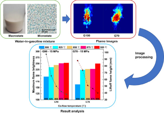
This study explores the flame characteristics of gasoline and a water-in-gasoline mixture and provides some optimization suggestions for the control strategy of water-in-gasoline mixture injection in the internal combustion Rankine cycle engines. The influences of co-flow temperature, injection pressure condition, and water content on the flame characteristics were investigated under a controllable high-temperature thermal atmosphere, including flame pattern, liftoff height, brightness, and local peak temperature distribution. Results obtained show that the water content has the most significant effect on the flame characteristics. The flame pattern gradually changes from slender to lumpy as the water content rises, while the high-temperature zone increases and becomes uniform. There is an appropriate water content range of 10–20% in which the flame characteristics are generally better. Furthermore, as the water content increases from 20 to 30%, the flame characteristics deteriorate, with a sharp decrease in the maximum flame temperature and brightness.
1. Introduction
Along with the burgeoning global economy, carbon neutrality and peak carbon dioxide emissions have become common goals worldwide.1 However, excessive consumption of fossil fuels in industrialization brings lots of carbon emissions, causing environmental pollution and climate change, which restrict the sustainable development of society and endanger human health.2 Therefore, efficiently and cleanly utilizing fossil fuels is the top priority of current research. In the automotive field, where fossil fuels are widely used, it is necessary to develop ultra-high thermal efficiency and ultra-low emission advanced internal combustion engine technologies.3
For gasoline engines, integration and innovation of technologies are needed to reduce emissions while improving the average thermal efficiency, including miniaturization, high supercharging, ultra-high compression ratio, optimized combustion cycle and control strategies, and so forth.4−7 Nonetheless, pre-ignition, knocking, and even highly violent super knocking occur in the application process of miniaturization, high supercharging, and ultra-high compression ratio, limiting the improvement of thermal efficiency and worsening emission characteristics. Therefore, delayed spark timing,8 a rich fuel–air mixture,9 and exhaust gas recirculation10 are used in concert to suppress knocking, while they are at the expense of engine power or fuel consumption.
In order to improve thermal efficiency while keeping high engine performance, Professor Bilger proposed the internal combustion Rankine cycle (ICRC) as an advanced gasoline combustion mode.11 An appropriate amount of water is injected during the combustion process to effectively control the combustion temperature in the cylinder, which can suppress the knocking tendency. More importantly, the expanding water steam works during the power stroke; thereby, the higher indicated mean effective pressure (IMEP) and thermal efficiency can be reached. The water injection technology plays an essential role in the ICRC.
At present, the water injection technologies applied in gasoline engines are mainly divided into three types: port water injection (PWI), direct water injection (DWI), and water-in-gasoline mixture injection in-cylinder. Zhu et al.12 and Hermann et al.13 elaborated on different water injection concepts in their reviews. According to their research, the characteristics and differences of these three water injection technologies could be clarified.
Till date, many studies on PWI and DWI of gasoline engines have been carried out. For PWI, Worm et al.14 investigated the impact of water injection on the engine combustion cycle, with an emphasis on high load operation. Their experimental results showed that water injection could decrease exhaust gas temperature and improve thermal efficiency at full load conditions. Li et al.15 explored the feasibility of water injection in the intake port to reduce the knock tendency of gasoline direct injection (GDI) engines and the effects of different water injection pressures on combustion and emissions by numerical simulation methods. They found that water injection technology could significantly reduce the knock intensity and NOx emissions, especially when the injection pressure is 5 bar. For DWI in-cylinder, Mingrui et al.16 investigated the influence of variable water injection by mass on the performance and emission characteristics of a GDI engine under light load conditions. The results indicated that a 15% water injection by mass used together with fuel gave the best engine performance. Hunger et al.17 compared the benefits and drawbacks of the various water injection technologies based on single-cylinder engine tests as well as computational analyses. They presented that DWI could provide immense potential in avoiding knock and reducing exhaust gas temperature.
According to the above studies, it can be found that the effects of these two water injection technologies have the advantage of engine performance improvement and knock suppression. The main advantage of PWI is the easy implementation, similar to a port fuel injection (PFI) system.12 Generally, the gasoline PFI system can be directly used for the PWI with little modifications.14 Compared to PWI, DWI has tremendous advantages in precise injection timing control, fuel atomization quality, and cooling effect, directly affecting the in-cylinder combustion process.18 However, DWI is complex because it needs to redesign the cylinder head and additional water injection system, which increases retrofit costs and limits its application.
Water-in-gasoline mixture injection in-cylinder is easy to retrofit, while it has the advantages of direct injection in the cylinder. Further, this injection method can improve the atomization quality of the spray at high temperature and then provides more possibilities for promoting fuel–air mixing and the combustion process.19 Therefore, the water-in-gasoline mixture injection has great research potential.
The concept of water-in-gasoline mixture injection is inspired by water-in-diesel mixture injection. Presently, the applications of water-in-diesel mixture injection in diesel engines are relatively mature. Many diesel engine bench tests using water-in-diesel mixture injection were carried out to reduce NOx and PM emissions effectively. The different conditions’ effects on the performance and emissions were explored, including water content (0–45%), different injection systems, and injection strategies.20−25 In contrast, studies on water-in-gasoline mixture injection are rare. In 1979, Feuerman26 prepared the water-in-gasoline mixture applied in conventional gasoline engines by mixing gasoline, water, and surfactants. Since then, Nguyen et al.27 and Heinrich et al.28 conducted bench tests using water-in-gasoline mixture injection. Their experimental results showed that the water-in-gasoline injection could also significantly improve anti-knock performance and reduce fuel consumption and NOx emission. Still, the excessive water content of the water-in-gasoline mixture would lead to unstable combustion. Qadiri29 explored the emission characteristics of the engine fuelled with conventional gasoline, ethanol blends, and a water-in-gasoline mixture through simulation calculations. It could be concluded from the calculation results that the water-in-gasoline mixture injection has enormous potential to reduce fuel consumption and emissions. Similarly, it would lead to unstable combustion under high-water-content conditions. According to the current studies, it is not difficult to find that clarifying the appropriate water content range of the water-in-gasoline mixture is the key to optimizing combustion. Besides, in the high-water-content conditions of the ICRC engine, optimization strategies for flame characteristics should be proposed to ensure stable combustion.
Our research group has been studying the ICRC for many years. Studies on ICRC engines with different fuels (gasoline, diesel, and propane), ignition modes (spark ignition and compression ignition), and water injection strategies (PWI and DWI) have been carried out successively.30−33 The previous engine bench tests showed that water injection technology could significantly improve engine performance and emission characteristics under full load conditions while effectively controlling in-cylinder temperature to suppress knocking. We also found that excessive water injection could prolong combustion duration and worse combustion. Currently, we are investigating the application of the water-in-gasoline mixture injection in the ICRC engine. Before carrying out the engine bench test using water-in-gasoline mixture injection, fundamental spray and combustion studies are conducted. It can decouple the research problem from the complex combustion process in the engine cylinder, directly and efficiently studying the variation law for spray and flame under different influences. Also, the results of fundamental research can provide theoretical support for engine bench tests.
Since the water intervention makes the physical properties of such immiscible mixtures extraordinarily different from the traditional fuels, we started the fundamental spray experiment to compare the spray characteristics of gasoline and water-in-gasoline mixtures.19 In this work, we explore the fundamental flame characteristics of water-in-gasoline mixtures based on a Dibble burner.34 The influences of co-flow temperatures (800–900 °C), fuel injection pressures (5 and 15 MPa), and water contents (0–30%) on flame characteristics are studied. The correlation between the water-in-gasoline mixture’s spray characteristics and flame characteristics is analyzed. Ultimately, we aim to determine the appropriate water content range according to the flame characteristics and provide optimization suggestions for the next ICRC engine bench test applying water-in-gasoline mixture injection.
The following text introduces the preparation of water-in-gasoline, experimental system, image processing method, and definition of flame parameters in Section 2. The variations of the water-in-gasoline mixture’s flame characteristics with the boundary conditions are discussed in Section 3.
2. Methodology
2.1. Preparation of Water-in-Gasoline
The preparation method of the water-in-gasoline mixture is mentioned in the previous research.19 G100, G90, G80, and G70 represent the different water contents. For example, G100 represents pure gasoline, while G80 represents the mixture of 80% gasoline and 20% water by volume. Here is an instance of configuring a G80. Add gasoline and deionized water into a container at a ratio of 8:2 first, and then add the emulsion according to 1% of the total volume. Next, stir the mixture with a high-speed stirrer at 10,000 rpm for 30 min. The water-in-gasoline mixture prepared can attain stability within 40 min. Each test of this experiment is guaranteed to be completed within 30 min. If it cannot be done, reprepare the mixture.
The macrostate of the G80 and its microscopic observation results are shown in Figure 1. The image taken by the microscope is grayscaled first and then binarized according to the distribution of the grayscale histogram with the OTSU’s algorithm. As shown in Figure 1c, the black area is gasoline, while the white area is water. Obtained by statistical calculation, the area ratio of gasoline and water is 0.7935:0.2065, which is extremely close to the actual preparation ratio.
Figure 1.

G80 macrostate (a), microscopic image (b), and microscopic image binarization result (c).
2.2. Experimental Apparatus and Conditions
2.2.1. Experimental Apparatus
A combustion synchronous measurement experimental system was built for this experiment. The schematic of the experimental system is shown in Figure 2. The actual picture of the experimental setup is shown in Figure 3. The central part of the system is a Dibble burner, which can provide a stable thermal atmosphere of 500–1200 °C. The blower continuously supplies oxygen to the Dibble burner, while the H2 bottle provides hydrogen. Hydrogen and oxygen are premixed inside the burner and then ignited above the burner. The co-flow field temperature of the burner is provided by the H2–O2 combustion products and measured by a B-type thermocouple with a precision of 0.5%. The turbulence intensity of the co-flow field can be effectively controlled by adjusting the air flow of the blower.
Figure 2.

Schematic of combustion synchronous measurement experimental system.
Figure 3.

Actual picture of the experimental setup.
The visual images of jet flames are captured by a Phantom V7.3 high-speed camera with the frame number set to 2000 fps, an exposure time of 498 μs, and an image resolution of 512 × 512 pixels. The flame temperature distribution is recorded with a FLIR SC7700 infrared camera with the frame number set to 110 fps, an exposure time of 1369 μs, and an image resolution of 640 × 512 pixels. The emissivity of the infrared camera is set to 0.29.
The fuel injection part consists of a gas–liquid compressor, a nitrogen cylinder, a GDI injector, and an injector fixture. A gas–liquid compressor is used to supply stable fuel injection pressure. When the signal pulse is received, the GDI injector starts injection, and two cameras record the combustion process simultaneously.
2.2.2. Experimental Conditions
The experimental conditions in this study are listed in Table 1. A GDI single-hole fuel injector with a diameter of 0.5 mm is used. The injection pressures are 5 and 15 MPa, while the water content varies from 0 to 30%. The co-flow temperature is set in a high-temperature range (800–900 °C) close to the ICRC gasoline engine operating conditions. Each experimental operating condition is repeated five times. The specific experimental procedures are shown in Figure 4.
Table 1. Experimental Conditions.
| GDI injector aperture (mm) | 0.5 |
| gasoline octane number | 92 |
| injection period (ms) | 2 |
| water content of mixture (volume, %) | 0, 10, 20, 30 |
| temperature of the mixture (°C) | 25 |
| injection pressure (MPa) | 5, 15 |
| ambient temperature (°C) | 800, 825, 850, 875, 900 |
| blower volume flow (m3/h) | 100 |
Figure 4.

Flow chart of experimental procedures.
2.2.3. Image Processing Methods
In this paper, Python is used to process visual images of the flame. First, the original image is subtracted from the background to obtain the preliminary flame shape. Next, the image is converted into a grayscale image. Then, pseudo-color processing can be performed on the grayscale image to obtain the pseudo-color image. The pseudo-color map from deep blue to deep red represents the flame brightness from low to high. Finally, the grayscale image is binarized into a binary image at a threshold of 5, used for flame feature extraction and calculation. At this threshold, the flame shapes in the original, binarized, and pseudo-color images are the closest. The processed images for each step of image recognition are shown in Figure 5.
Figure 5.

Processed images of image recognition: (a) original image, (b) pseudo-color image, and (c) binarized image.
The flame temperature distribution in the axial direction from the flame base and the radial direction at the flame’s widest position are extracted from infrared images. The specific processing is shown in Figure 6: (a) infrared image, (b) temperature extraction in axial and radial, and (c) temperature distribution curve fitting and local peak temperature extraction.
Figure 6.

Processing of flame temperature distribution: (a) infrared image, (b) temperature extraction in axial and radial, and (c) local peak temperature extraction.
2.2.4. Definition of Flame Parameters
The fluctuation of the liftoff flame within 5 ms after injection is relatively tiny. Therefore, the flame image at 5 ms is taken for analysis. The liftoff flame height is the distance from the lowest point of the jet flame to the injector outlet. The maximum flame brightness refers to the maximum gray value of the flame image.
The local peak temperature distribution is used to describe the coverage of the high-temperature zone in the axial direction and the radial direction. As shown in Figure 6c, the local peak temperature points are connected to a blue polyline. The distance in the x-axis direction of the blue polyline is defined as the local peak temperature distribution in the axial direction. The temperature corresponding to the highest point is the maximum flame temperature in the axial direction.
3. Results and Discussion
3.1. Flame Pattern
The flame pattern at 5 ms after injection is selected for comparison and analysis. Figure 7 shows the variation of flame pattern for G100 and G70 with the co-flow temperature at the injection pressure of 15 MPa. As the co-flow temperature increases, the flame brightness gradually rises, and the boundary of the flame pattern becomes more evident. In addition, high-temperature points of the flame pattern are gradually connected into blocks.
Figure 7.

Flame pattern for G100 and G70 varies with co-flow temperature.
The increase of co-flow temperature accelerates the fuel evaporation process, promoting the formation of the combustible mixture. Furthermore, the higher co-flow temperature is beneficial to the accumulation of ignition energy, which intensifies the chemical reaction and contributes to the full release of heating value. These can explain the variation in the flame brightness and the distribution of the high-temperature zone.
At the experimental temperatures, the flame shape of G100 is slender with noticeable wrinkles, and the high-temperature zone is unevenly distributed in deep red. Differently, the flame shape of G70 is lumpy, and the high-temperature zone is uniformly distributed in bright red. The previous research19 compares G100 and G70 spray patterns. The results show that water intervention can change the spray from slender with escalated wrinkles to pronounced collapsed. The variation of the spray pattern may strongly influence the flame pattern.
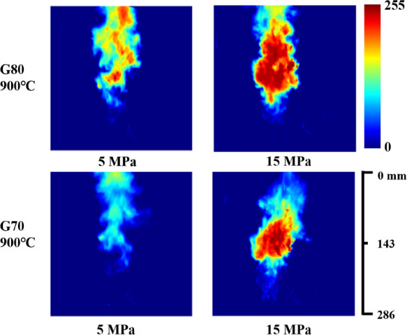
Figure 8 shows a comparison of the flame pattern of water-in-gasoline mixtures at the injection pressures of 5 and 15 MPa. The co-flow temperature is 900 °C. Compared with the injection of 5 MPa, the high-temperature zone of the flame at the injection pressure of 15 MPa increases significantly, and the flame is brighter as a whole. It is known that higher injection pressure means better breakup and atomization of the liquid fuel, which contributes to complete combustion. More importantly, when the injection period is constant, there is more fuel injection quantity at the injection pressure of 15 MPa, so a larger high-temperature zone.
Figure 8.
Flame pattern for G80 and G70 at the injection pressures of 5 and 15 MPa.
The flame characteristics of the water-in-gasoline mixture at low injection pressure are poor due to insufficient fuel. Nguyen’s research27 also mentions that the too lean water-in-gasoline mixture at a high air–fuel ratio decreases combustion stability, which causes the occurrence of the misfire. Moreover, Heinrich et al.28 propose that increasing the equivalence ratio may improve the combustion stability at the high water content. Similar to improving the injection pressure, improving the equivalence ratio also increases the amount of fuel to improve combustion stability. Thus, in the high-water-content conditions of the ICRC engine, it is recommended to supplement the fuel amount during the combustion process for better flame characteristics and combustion stability appropriately, such as increasing the injection pressure, extending the injection period, and so forth.
Figure 9 shows the variation of the flame pattern with water content. The injection pressure is 15 MPa, and the co-flow temperature is 900 °C. Compared with pure gasoline, the high-temperature zone of the water-in-gasoline mixture flame significantly increases, and the distribution is more uniform. The flame pattern gradually changes from slender to lumpy as the water content rises. Differences in gasoline and water-in-gasoline flame patterns can be explained by comparing spray patterns. Figure 10 shows the spray patterns for G100 and G70 with the injection pressure of 15 MPa and the initial temperature of 140 °C. It can be seen that there are more wrinkles on the wings of the G100 spray, which means a more intense interaction force between air and jet. The reason is that G100 has a higher gas–liquid density ratio than that of G70. The intense interaction between the gas and the liquid accelerates the evaporation of the G100 spray’s two wings. Therefore, the spray pattern of G100 is slender than that of G70. The spray pattern directly affects the flame pattern, so the G100 flame is slender.
Figure 9.

Flame pattern varies with water content.
Figure 10.

Spray patterns for G100 and G70 with the injection pressure of 15 MPa and the initial temperature of 140 °C.
The water intervention increases the spray cone angle of the water-in-gasoline mixture under the same conditions, which facilitates the development of the spray in the radial direction.19 In addition, the impact of the micro-explosion phenomenon of the water-in-gasoline mixture at high temperatures further promotes the spray development trend in radial. Thus, the flame pattern gradually changes to lumpy as the water content rises. During the micro-explosion process, the low-boiling liquid is vaporized first and impacts the rest of the liquid. On the one hand, this gas–liquid interaction promotes the fragmentation of the spray, possibly increasing the uniformity of the flame. On the other hand, the micro-explosion enhances the spatial dispersion of the water-in-gasoline mixture spray and makes its spray area larger than that of the pure gasoline spray,19 which may be the reason for the increase in the high-temperature zones.
However, the effect of water intervention is not entirely favorable. In the water content range of 10–20%, the flame patterns are significantly better due to the enlargement of the high-temperature zone and the increase in uniformity. The reason behind this result is explained in the upper paragraph. The high-temperature zone significantly decreases as the water content rises from 20 to 30%. The reason is that the excess water vaporization absorbs the heat released by the combustion, which inhibits the diffusion of the fire core to the outside and reduces the overall flame temperature. In conclusion, there is an appropriate water content range of 10 to 20%, in which the flame pattern may be optimized.
3.2. Liftoff Flame Height and Maximum Flame Brightness
The liftoff flame height and maximum flame brightness vary with the co-flow temperature at the injection pressure of 15 MPa, as shown in Figure 11. The curve in Figure 11 represents the liftoff flame height, while the histogram represents the maximum flame brightness. The liftoff flame height reflects the ignition delay time. As the co-flow temperature increases from 800 °C, the liftoff height decreases significantly because the higher co-flow temperature enhances the heat transfer between fuel and thermal atmosphere, shortening the ignition delay time.
Figure 11.

Liftoff flame height and flame brightness vary with co-flow temperature.
There is a critical temperature of 850 °C, above which the liftoff flame height is more stable, and flame brightness gradually reaches saturation. The reason is that when the co-flow temperature reaches the critical temperature, a vigorous chemical reaction has been thoroughly carried out inside the flame. Due to the correlation between flame brightness and the chemical reaction process, the flame brightness changes little when the co-flow temperature is high enough.
The above influence law of co-flow temperature has reference significance for the control of ambient temperature in the engine cylinder. If the ambient temperature before fuel injection is too low, it will prolong the ignition delay time, which is not conducive to optimizing the combustion phase. Thus, under similar working conditions in the ICRC engines using the water-in-gasoline mixture injection, it is recommended to control the ambient temperature in the range of 850–900 °C.
Figure 12 shows the variations of liftoff flame height and maximum flame brightness with the water content at the injection pressure of 15 MPa. It can be seen that the effect of water content on the liftoff height is diverse at different co-flow temperatures. When the co-flow temperature is 800 °C, the liftoff flame height decreases by 24.2% as the water content increases to 10%. At this temperature, the water intervention may promote the breakup and atomization of the spray, which effectively shortens the physical ignition delay time. As the water content continues to increase, the liftoff height and brightness tend to stabilize. The liftoff height increases, and the maximum flame brightness decreases due to the water intervention at 900 °C. The liftoff flame heights are overall lower, and the flame brightness tends to be saturated. At this time, the inhibitory effect of water may play the dominant role in combustion, extending the ignition delay time and inhibiting the rate of chemical reactions.
Figure 12.

Liftoff flame height and maximum flame brightness vary with water content.
The maximum flame brightness and liftoff height are generally better in the 10–20% water content. The experimental result of Heinrich et al.28 shows that the specific fuel consumption has a significant reduction in the range of 15–30% water fuel ratio (10.5–21% water content) at different engines speeds, which has good consistency with the optimal range of water content proposed in this paper. The correlation shows that optimizing the water content range may be vital in improving in-cylinder combustion in the actual engine. Combined with the variation of flame pattern with water content, when applying water-in-gasoline mixture injection in the ICRC engine, the water content range is considered to be controlled at 10 to 20% to optimize the in-cylinder combustion.
3.3. Flame Local Peak Temperature Distribution
The flame local peak temperature distribution and maximum flame temperature of G100 vary with the co-flow temperature, as shown in Figure 13. The injection pressure is 5 MPa. The curve in Figure 13 represents the maximum flame temperature, while the histogram represents the local peak temperature distribution. As the co-flow temperature rises, the distribution range of the local peak temperature gradually becomes more extensive, particularly in the axial direction. Also, the maximum flame temperature increases rapidly, especially in the radical direction.
Figure 13.

Local peak temperature distribution and maximum flame temperature vary with co-flow temperature.
The increase of co-flow temperature accelerates heat transfer between the jet and the high-thermal atmosphere and promotes the multi-point spontaneous combustion of fuel. As a result, the high-temperature zone widens. The G100 spray mainly develops in the axial direction of the injector, which may be the reason for the more obvious change trend in the axial direction. The chemical reaction between the fuel and the oxidant is more intense at higher temperatures, conducive to complete heat release, which makes the maximum flame temperature higher.
The local peak temperature distributions and maximum flame temperatures of gasoline and water-in-gasoline mixtures with different water contents are shown in Figure 14. The injection pressure is 5 MPa, and the co-flow temperature is 900 °C. The representation of Figure 14 is similar to that of Figure 13. Overall, the local peak temperature distribution range becomes more extensive with the increase of water content, which is related to the variation of the flame pattern. The maximum flame temperature decreases as the water content rises.
Figure 14.

Local peak temperature distribution and maximum flame temperature vary with water content.
There is a critical water content of 20%, above which the maximum flame temperature sharply reduces. The maximum flame temperature reduces from 1776 to 1340 °C in the axial direction, while it reduces from 2088 to 1447 °C in the radial direction. The incorporation of water increases the overall specific heat capacity of the water-in-gasoline mixture and reduces the total heat released by combustion, which is detrimental to the temperature rise. Moreover, the water vaporization process will absorb a large amount of heat released by combustion, which is not conducive to flame propagation. When the water content is excessive, flame propagation is inhibited so that the heat of the fuel cannot be released sufficiently, which causes a sudden drop in maximum flame temperature.
Similarly, in Nguyen et al.’s research,27 the coefficient of variance of IMEP significantly increased for the 15% water content. According to these results, it can be concluded that excessive water content will deteriorate the flame characteristics with a sharp reduction in flame temperature, causing unstable combustion in the gasoline engine. The instability of the water-in-gasoline mixture in Nguyen’s experiment is poor due to the slow stirring speed (5000 rpm) and short stirring time (10 min). As a result, unstable combustion occurs in the lower water content (15%).
In practical engine applications, the sudden decrease in flame temperature can lead to unstable combustion and even misfire. For this reason, when water-in-gasoline mixture injection is applied in ICRC engines, the water content is recommended not to exceed 20% to ensure stable combustion.
4. Conclusions
The flame characteristics of gasoline and the water-in-gasoline mixture were investigated based on the combustion synchronous measurement experimental system. Several optimization suggestions for the control strategy of water-in-gasoline mixture injection applied in ICRC engines were proposed. The main conclusions are as follows:
-
(1)
As the co-flow temperature increases, the liftoff flame height of gasoline and the gasoline–water mixture decreases continuously, while the maximum flame brightness, maximum flame temperature, and local peak temperature distribution increase. There is a critical temperature of 850 °C, above which the liftoff flame height is more stable, and flame brightness gradually reaches saturation.
-
(2)
The water-in-gasoline mixture’s flame patterns are apparent and distinct at different injection pressures. Compared with the injection pressure of 5 MPa, the high-temperature zone of the flame pattern at 15 MPa increases significantly, and the flame is brighter as a whole.
-
(3)
As water content rises, the flame pattern gradually changes from slender to lumpy, while the high-temperature zone increases and becomes uniform. The flame characteristics are better in the 10 to 20% water content. The maximum flame temperature and brightness decrease sharply above 20% water content.
-
(4)
Under similar operating conditions in the ICRC engines, the appropriate ambient temperature in-cylinder (850–900 °C) and the water content of the water-in-gasoline mixture (10–20%) are advised to optimize flame characteristics and ensure stable combustion. Increasing the injection pressure appropriately in high-water-content conditions is suggested.
Applying the water-in-gasoline mixture injection in ICRC engines has considerable development potential. In future work, the combustion process of the water-in-gasoline mixture will be investigated through engine bench tests. Diverse fuel compositions will be considered to reduce the inhibitory effect of water on combustion at high-water-content conditions.
Acknowledgments
This work was supported by the National Natural Science Foundation of China (nos. U1832179, 52076153).
Glossary
Abbreviations
- ICRC
internal combustion Rankine cycle
- IMEP
indicated mean effective pressure
- PWI
port water injection
- DWI
direct water injection
- PFI
port fuel injection
- GDI
gasoline direct injection
- COV
coefficient of variance
Author Contributions
The manuscript was written through contributions of all authors. All authors have given approval to the final version of the manuscript.
The authors declare no competing financial interest.
References
- Yang S.; Yang D.; Shi W.; Deng C.; Chen C.; Feng S. Global evaluation of carbon neutrality and peak carbon dioxide emissions: current challenges and future outlook. Environ. Sci. Pollut. Res. 2022, 1–20. 10.1007/s11356-022-19764-0. [DOI] [PMC free article] [PubMed] [Google Scholar]
- Kennedy I. M. The health effects of combustion-generated aerosols. Proc. Combust. Inst. 2007, 31, 2757–2770. 10.1016/j.proci.2006.08.116. [DOI] [Google Scholar]
- Zheng G. Research on energy saving and emission reduction of urban transportation under the concept off low-carbon life. E3S Web Conf. 2021, 248, 02025. 10.1051/e3sconf/202124802025. [DOI] [Google Scholar]
- He B. Q.; Liu M. B.; Yuan J.; Zhao H. Combustion and emission characteristics of a HCCI engine fuelled with n-butanol-gasoline blends. Fuel 2013, 108, 668–674. 10.1016/j.fuel.2013.02.026. [DOI] [Google Scholar]
- Lu X.; Han D.; Huang Z. Fuel design and management for the control of advanced compression-ignition combustion modes. Prog. Energy Combust. Sci. 2011, 37, 741–783. 10.1016/j.pecs.2011.03.003. [DOI] [Google Scholar]
- Li X.; Zhen X.; Xu S.; Wang Z.; Liu D.; Tian Z. Numerical comparative study on knocking combustion of high compression ratio spark ignition engine fueled with methanol, ethanol and methane based on detailed chemical kinetics. Fuel 2021, 306, 121615. 10.1016/j.fuel.2021.121615. [DOI] [Google Scholar]
- Chen L.; Wei H.; Pan J.; Liu C.; Shu G. Understanding the correlation between auto-ignition, heat release and knocking characteristics through optical engines with high compression ratio. Fuel 2020, 261, 116405. 10.1016/j.fuel.2019.116405. [DOI] [Google Scholar]
- De Bellis D. B.; Bozza B.; Teodosio T.; Valentino V. Experimental and Numerical Study of the Water Injection to Improve the Fuel Economy of a Small Size Turbocharged SI Engine. SAE Int. J. Engines 2017, 10, 550–561. 10.4271/2017-01-0540. [DOI] [Google Scholar]
- Chang C.; Wei M. Effect of key parameters on knock suppression in a two-stroke spark ignition engine with aviation kerosene fuel. Proc. Inst. Mech. Eng. J. Power Eng. 2019, 233, 1047–1055. 10.1177/0957650919842008. [DOI] [Google Scholar]
- Tornatore C.; Bozza F.; De Bellis V.; Teodosio L.; Valentino G.; Marchitto L. Experimental and numerical study on the influence of cooled EGR on knock tendency, performance and emissions of a downsized spark-ignition engine. Energy 2019, 172, 968–976. 10.1016/j.energy.2019.02.031. [DOI] [Google Scholar]
- Bilger R. W.; Wu Z. Carbon Capture for Automobiles Using Internal Combustion Rankine Cycle Engines. J. Eng. Gas Turbines Power 2009, 131, 034502–034505. 10.1115/1.3077657. [DOI] [Google Scholar]
- Zhu S.; Hu B.; Akehurst S.; Copeland C.; Lewis A.; Yuan H.; Kennedy L.; Bernards J.; Branney C. A review of water injection applied on the internal combustion engine. Energy Convers. Manage. 2019, 184, 139–158. 10.1016/j.enconman.2019.01.042. [DOI] [Google Scholar]
- Hermann I.; Glahn C.; Kluin M.; Paroll M.; Gumprich W. P.. Water Injection for Gasoline Engines—Quo Vadis?. International Conference on Knocking in Gasoline Engines; Springer International Publishing: Cham, 2017, pp 299–321.
- Worm J.; Naber J.; Duncan J.; Barros S.; Atkinson W. Water Injection as an Enabler for Increased Efficiency at High-Load in a Direct Injected, Boosted, SI Engine. SAE Int. J. Engines 2017, 10, 951–958. 10.4271/2017-01-0663. [DOI] [Google Scholar]
- Li A.; Zheng Z.; Song Y. A Simulation Study of Water Injection Position and Pressure on the Knock, Combustion, and Emissions of a Direct Injection Gasoline Engine. ACS Omega 2021, 6, 18033–18053. 10.1021/acsomega.1c01792. [DOI] [PMC free article] [PubMed] [Google Scholar]
- Mingrui W.; Thanh Sa S. N.; Turkson R. F.; Jinping L.; Guanlun G. Water injection for higher engine performance and lower emissions. J. Energy Inst. 2017, 90, 285–299. 10.1016/j.joei.2015.12.003. [DOI] [Google Scholar]
- Hunger M.; Böcking B.; Walther U.; Günther G.; Freisinger K.; Karl G.. Potential of Direct Water Injection to Reduce Knocking and Increase the Efficiency of Gasoline Engines. International Conference on Knocking in Gasoline Engines; Springer International Publishing: Cham, 2017, pp 338–359.
- Pei Y.; Zhang Q.; Peng Z.; An Y.; Shi H.; Qin J.; Zhang B.; Zhang Z.; Gao D. Thermal efficiency improvement of lean burn high compression ratio engine coupled with water direct injection. Energy Convers. Manage. 2022, 251, 114969. 10.1016/j.enconman.2021.114969. [DOI] [Google Scholar]
- Wu Z.; Xie W.; Yu Y.; Li L.; Deng J. Comparison of spray characteristics of gasoline and water-in-gasoline mixture at elevated fuel temperature conditions. Fuel 2021, 304, 121409. 10.1016/j.fuel.2021.121409. [DOI] [Google Scholar]
- González D. M.; Rivas H.; Gutiérrez X.; León A. Performance and Emissions Using Water in Diesel Fuel Microemulsion. SAE Int. J. Engines 2001, 1, 3525. 10.4271/2001-01-3525. [DOI] [Google Scholar]
- Lin C. Y.; Wang K. H. Effects of a Combustion Improver on Diesel Engine Performance and Emission Characteristics When Using Three-Phase Emulsions as an Alternative Fuel. Energy Fuels 2004, 18, 477–484. 10.1021/ef0300848. [DOI] [Google Scholar]
- Alahmer A.; Yamin J.; Sakhrieh A. M. A.; Hamdan M. A. Engine performance using emulsified diesel fuel. Energy Convers. Manage. 2010, 51, 1708–1713. 10.1016/j.enconman.2009.11.044. [DOI] [Google Scholar]
- Maiboom A.; Tauzia X. NOx and PM emissions reduction on an automotive HSDI Diesel engine with water-in-diesel emulsion and EGR: An experimental study. Fuel 2011, 90, 3179–3192. 10.1016/j.fuel.2011.06.014. [DOI] [Google Scholar]
- Saitoh H.; Uchida K.. Feasibility Study on the Utilization of Water-In-Oil Type Emulsified Fuels to Small Di Diesel Engines. SAE Technical Papers, 2011.
- Basha J. S.; Anand R. B. Effects of nanoparticle additive in the water-diesel emulsion fuel on the performance, emission and combustion characteristics of a diesel engine. Int. J. Veh. Des. 2012, 59, 164–181. 10.1504/IJVD.2012.048692. [DOI] [Google Scholar]
- Feuerman A. I.Gasoline-water emulsion. U.S. Patent 4,158,551 A, 1979.
- Nguyen Q. A.; Wu Y. Y.. B104 experimental investigations of using water-gasoline emulsions as a Nox treatment and its effects on performance and emissions of lean-burn spark-ignition engine (combustion-1). The Proceedings of the International Conference on Power Engineering (ICOPE) 2009.1; The Japan Society of Mechanical Engineers, 2009.
- Heinrich C.; Dörksen H.; Esch A.; Krämer K.. Gasoline Water Direct Injection (GWDI) as a Key Feature for Future Gasoline Engines. Knocking in Gasoline Engines; Springer International Publishing: Cham, 2017, pp 322–337. [Google Scholar]
- Qadiri U. Computational parametric investigation on single cylinder constant speed spark ignition engine fuelled water-based micro-emulsion, ethanol blends, and conventional gasoline. Mater. Sci. Energy Technol. 2021, 4, 256–262. 10.1016/j.mset.2021.07.002. [DOI] [Google Scholar]
- Wu J.; Zhang Z.; Kang J.; Deng L.; Li Z.; Wu Z. An assessment methodology for fuel/water consumption co-optimization of a gasoline engine with port water injection. Appl. Energy 2022, 310, 118567. 10.1016/j.apenergy.2022.118567. [DOI] [Google Scholar]
- Kang Z.; Zhang Z.; Deng J.; Li L.; Wu Z. Experimental Research of High-Temperature and High-Pressure Water Jet Characteristics in ICRC Engine Relevant Conditions. Energies 2019, 12, 1763. 10.3390/en12091763. [DOI] [Google Scholar]
- Fu L.; Wu Z.; Yu X.; Deng J.; Hu Z.; Li L. Experimental Investigation of Combustion and Emission Characteristics for Internal Combustion Rankine Cycle Engine under Different Water Injection Laws. Energy Proc. 2015, 66, 89–92. 10.1016/j.egypro.2015.02.047. [DOI] [Google Scholar]
- Wu Z.; Wu J.; Kang Z.; Deng J.; Hu Z.; Li G. A review of water-steam-assist technology in modern internal combustion engines. Energy Rep. 2021, 7, 5100–5118. 10.1016/j.egyr.2021.08.104. [DOI] [Google Scholar]
- Cabra R.; Dibble R. W.; Chen J. Y.. Characterization of Liquid Fuel Evaporation of a Liftoff Methanol Spray Flame in a Vitiated Co-flow Burner, NASA Report. NASA/CR-2002-212083.