Abstract
Background
Our study aims to validate a commercially available inertial measurement unit (IMU) system against a standard laboratory-based optical motion capture (OMC) system for shoulder measurements in a clinical context.
Methods
The validation analyses were conducted on 19 healthy male volunteers. Twelve reflective markers were placed on each participant’s trunk, scapula and across the arm and one IMU was attached via a self-adhesive strap on the forearm. A single tester simultaneously collected shoulder kinematic data for four shoulder movements: flexion, extension, external rotation, and abduction. Agreement between OMC system and IMU measurements was assessed with Bland-Altman analyses. Secondary analysis included mean biases, root mean square error (RMSE) analysis and Welch’s t-test.
Results
Bland-Altman limits of agreement (LoA) exceeded the acceptable range of mean difference for 95% of the population (−22.27°, 11.31°). The mean bias showed high levels of agreement within 8° for all four movements. More than 60% of participants demonstrated mean bias less than 10° between methods. Statistically significant differences were found between measurements for abduction (P<0.001) and flexion (P=0.027) but not for extension and external rotation (P≥0.05).
Conclusions
Our study shows preliminary evidence for acceptable accuracy of a commercially available IMU against an OMC system for assessment of shoulder movements by a single tester. The IMU also exhibits similar whole degree of error compared to a standard goniometer with potential for application in remote rehabilitation.
Keywords: Inertial measurement unit (IMU), motion tracking, goniometer, kinematics, remote rehabilitation
Introduction
The assessment of joint range of motion (RoM) is a critical step in the clinical evaluation of joint pathology. There are several methods for measuring RoM, ranging from visual estimation or easily accessible universal goniometers to laboratory equipment such as optical motion capture (OMC) systems. The universal goniometer remains the most widely adopted method to assess joint RoM, owing to its ease of use and portability. However, its accuracy varies according to the user’s skill level (1). On the other hand, OMC systems are considered the gold standard for RoM analysis, but its use is limited to laboratory settings (2). This highlights a gap in available methods for joint motion analysis that is both accurate and easily accessible.
In recent years, inertial measurement units (IMUs) have increased in popularity as a wearable motion capture system for joint analysis. IMUs utilise non-OMC sensors to collect a variety of data such as RoM, velocity, and acceleration (3). By capitalising on recent advancements on miniaturisation of motion capture sensors, IMUs provide a portable, non-invasive instrument for joint motion analysis.
While shoulder motion is produced by a combination of movements across several joints, many common shoulder pathologies such as rotator cuff syndrome, adhesive capsulitis, and shoulder dislocations usually involve the glenohumeral joint. Therefore, it is of particular importance to develop a portable, and accurate method of assessing kinematics of the glenohumeral joint. The complexity of the shoulder joint movement leads to difficulties in accurate measurement of joint kinematics without laboratory equipment. While continued use of laboratory equipment to measure joint kinematics is important, there is a growing interest in assessing joint motion outside of a laboratory setting (4,5). If the accuracy of IMUs is found to be comparable to that of OMC systems found in kinematic labs, the portability of IMUs would allow accurate evaluation of shoulder joint kinematics as part of routine clinical practice. For example, the clinical examination of patients with rotator cuff injuries usually involves RoM testing (6). The current practice is to measure shoulder RoM using a goniometer, which has been shown to have a minimal clinical difference of 22° compared to the gold standard (7). We believe that IMUs may present a superior alternative with increased accuracy, collection of real-time data, and simultaneous gathering of other kinematic parameters aside from RoM.
The aim of this study was to validate a commercially available IMU system against a standard laboratory-based OMC system for the measurement of shoulder flexion, extension, external rotation, and abduction. We present the following article in accordance with the TREND reporting checklist (available at https://mhealth.amegroups.com/article/view/10.21037/mhealth-22-7/rc).
Methods
Participants
The study was conducted in accordance with the Declaration of Helsinki (as revised in 2013). The study was approved by the institutional review board of Nanyang Technological University (No. IRB-2014-06-014) and informed consent was taken from all individual participants. Nineteen male volunteers aged between 24 to 26 years old participated in the study. All participants were screened to ensure that they did not suffer from previous or existing upper limb injuries and/or had impairments in upper limb RoM.
OMC system
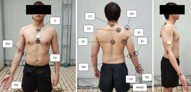
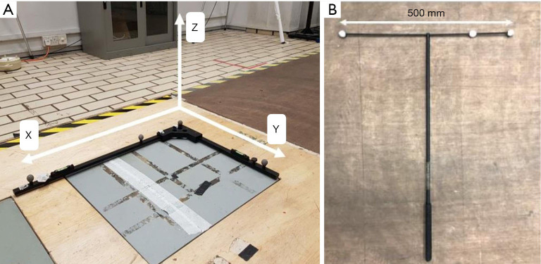
The OMC system comprised of six infra-red Eagle digital cameras (Motion Analysis Corp., Santa Rosa, CA, USA). 12 reflective markers for the OMC system were placed on the participant’s trunk, scapula, arm, and hand (Figure 1). The markers were recorded during the test protocol at a sample frequency of 100 Hz. Local anatomic coordinate systems were defined as recommended by the International Society of Biomechanics (Table S1) (8). Kinematic data collected by the OMC system was sent to a local computer and processed with the Cortex software (Motion Analysis Corp., Santa Rosa, CA, USA). Prior to experimentation, the OMC system underwent static and dynamic calibration. For static calibration, an L-frame with four retro-reflective markers was placed on the ground to construct the global X-Y-Z coordinate system (Figure 2A). Static calibration was successful when all four markers were detectable by each infra-red camera. For dynamic calibration, a 500 mm T-wand with three retro-reflective markers was waved in a figure-of-eight motion for 90 seconds (Figure 2B). Dynamic calibration is performed to establish the relationship between the image coordinates from markers on the target structure with respect to the global coordinate system. Dynamic calibration was successful when the Cortex software revealed average 3D residual values <0.5 and correctly estimated the wand length to be 500 mm.
Figure 1.
Positions of reflective markers for the gold standard optical motion capture system are shown. Four markers form the thorax coordinate system: xiphoid process (PX), suprasternal notch (IJ) and the C7, T8 vertebrae. Three markers form the scapula coordinate system: inferior angle of the scapula (IA), acromion (AA) and trigonum spinae (TS). Two markers form the humerus coordinate system: medial (EM) and lateral (EL) epicondyle. Finally, three additional markers form the forearm coordinate system: ulnar styloid (US), radial styloid (RS) and the dorsum of the hand (HAND). The images are published with the participant’s consent.
Figure 2.
Calibration setup for the optical motion capture system. (A) Shows the L-frame used in static calibration to construct the global X-Y-Z coordinate system. (B) Shows the 500 mm T-wand used for dynamic calibration.
Kinematic data from the Cortex software is filtered through a low band-pass Butterworth filter with a frequency of 6Hz and converted into joint angles using MATLAB® (R2019a, Mathworks Inc., Natick, MA, USA). First, we estimated the glenohumeral joint rotation centre (GH-JRC) using a mathematical sphere-fitting model in as shown in equation 1, which calculates an offset from each participant’s acromion (AA, Figure 1) as a palpable bony landmark (9).
| [1] |
Next, shoulder RoM was calculated using a rotation matrix constructed by rotating the thorax (global) coordinate system to fit into the humerus (local) coordinate system. The vector definitions for the thorax and humerus coordinate systems used in this study can be found in Table S2. Using both the thorax and humerus coordinate systems, a rotation matrix can be constructed by rotating the global coordinate system to fit into the local coordinate system. In our study, the YXY rotation sequence was used to produce 3 rotation angles, α, β, and δ, to describe plane of elevation, angle of elevation and axial rotation respectively (8). The following rotation matrices shows the rotation of the coordinate systems, where θ is an arbitrary angle:
| [2] |
The rotation matrix R with YXY sequence is then defined as:
| [3] |
| [4] |
Finally, expressions for Euler angles are obtained by solving the above matrix relation:
| [5] |
IMU
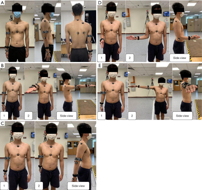
The XCLR8 IMU (XCLR8 Technologies Private Limited, Singapore) consists of a gyroscope, accelerometer, and magnetometer to assess motion. The IMU was attached to each participant via a self-adhering strap on the forearm, midway between the olecranon and the radial styloid (Figure 3A). Kinematic data from the IMU was sampled at a rate of 20 Hz and sent wirelessly to an android mobile device to be processed with the Rebee-Rehab software application (XCLR8 Technologies Private Limited, Singapore). The frequency of 20 Hz was chosen as it was the most effective way to send data from the sensor-phone-unity avatar without causing any visual delays in the real-time human avatar shown on the android mobile device. Assuming that the sense axes of the IMU is aligned with the anatomical axes of the humerus, quaternion data from the IMU is used to estimate shoulder RoM.
Figure 3.
Experimental setup depicting positions of reflective markers for the gold standard optical motion capture system and inertial measurement unit (IMU). (A) shows IMU attached to the forearm with a black self-adhesive strap. Participant is shown in (A) neutral position and performing (B) flexion up to 90°, (C) extension, (D) external rotation, (E) abduction up to 90°. The images are published with the participant’s consent.
Test protocol
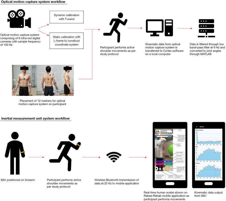
The IMUs were validated for four active movements: 90° flexion, extension, external rotation, and 90° abduction (Figure 3). In our study protocol, we chose 90° as a standardised range that most clinical patients would be expected to achieve. For example, certain post-operative patients may not be able to perform RoM past 90° in the perioperative period. A demonstration of the movement was conducted prior to each test and the participant practiced the movement until he was comfortable and performing it correctly. Participants used their dominant arm and were required to complete three sets of each motion. The starting and ending positions of each motion were held for two seconds. For each participant, static and dynamic calibration was performed to account for differences in individual body structure. First, the participant was instructed to maintain a neutral standing position for five seconds to create a static model. Following which dynamic calibration was performed by instructing the participant to swing their arm in a controlled, anti-clockwise motion for 25 seconds. For all trials, kinematic data from the OMC system and IMU were collected simultaneously and synchronised. All experiments were carried out by a single researcher (CCS) in the same motion analysis laboratory. A flowchart summarising the experimental workflow described in this section can be found in Figure 4.
Figure 4.
Experimental flow chart for both the optical motion capture (OMC) and inertial measurement unit (IMU) systems.
Statistical analysis
Shapiro-Wilk test was performed to check for normality of data. Group means and standard deviations are reported for all movements. Absolute differences between the gold standard OMC system and IMU system was calculated. Bland-Altman analysis was used to determine the limits of agreement (LoA) between the two measurement methods. Bland-Altman analysis quantifies the amount of agreement between two methods of measurement by constructing LoA. These limits are calculated by using the mean and standard deviation of the differences between two measurements. In Bland-Altman analysis, the LoA are defined as 95%, as the authors recommended that 95% of data points should lie within 2 standard deviations of the mean difference. The results of this analysis are conventionally displayed graphically using a scatter plot, in which the Y axis shows the difference between two paired measurements, and the X axis represents the average of these measurements (10,11). For the comparison of OMC system and IMU measurements, acceptable LoA was determined a priori to be within 10° of no difference between measurements (12,13). The relationship between kinematic data collected by the OMC and IMU systems were analysed by a linear regression, where the slope of the regression line and the coefficient of determination (R2) were calculated. In addition, sample-to-sample root mean square error (RMSE) and Welch’s t-test were performed to evaluate the means of measurements between OMC system and IMU. P value of <0.05 is taken to be statistically significant. All statistical analysis was performed in MATLAB and R version 4.1.1.
Results
All 19 participants completed all measurements for four movements—flexion, extension, external rotation, and abduction. For extension and external rotation movement, there was an error in OMC system data capture for one male subject. Therefore, only data from 18 participants were analysed. Shapiro-Wilk test revealed that the distribution of data was not significantly different from the normal distribution (P>0.05) and normality of our study population was assumed.
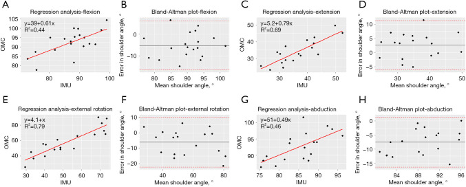
The mean bias between OMC system and IMU measurements was smallest for extension at 2.58°, whereas larger values were observed for flexion, external rotation, and abduction (Table 1). Additionally, according to reported mean biases, the IMU appears to underestimate the OMC for extension and overestimate joint angles for flexion, abduction, and external rotation. Our Bland-Altman analysis revealed LoAs greater than 10° of the mean difference on either side for all movements (Figure 5). However, more than 60% of participants demonstrated difference of less than 10° between measurement methods for all four movements (Table 2). Additionally, t-test showed statistically significant differences in abduction (P<0.001) and flexion (P=0.027) movements (Table 2). No statistically significant differences were found for extension and external rotation (P>0.05).
Table 1. Bland-Altman analysis: optical motion capture system versus IMU.
| Shoulder movements | Optical system mean, ° (SD) | IMU forearm mean, ° (SD) | Mean bias, ° (SD) | Lower LoA, ° | Lower LoA 95% CI, ° | Upper LoA, ° | Upper LoA 95% CI, ° |
|---|---|---|---|---|---|---|---|
| Flexion | 87.20 (7.25) | 92.40 (6.65) | −5.20 (5.72) | −16.41 | [−21.20, −11.61] | 6.00 | [1.21, 10.8] |
| Extension | 36.58 (7.84) | 34.00 (7.43) | 2.58 (4.45) | −2.29 | [−10.01, −6.15] | 11.31 | [7.45,15.17] |
| External Rotation | 52.44 (15.22) | 58.56 (17.81) | −6.12 (8.24) | −22.27 | [−29.41, −15.13] | 10.03 | [2.90, 17.17] |
| Abduction | 84.87 (6.19) | 92.42 (4.48) | −7.55 (4.54) | −16.45 | [−20.26, −12.64] | 1.35 | [−2.46, 5.16] |
Mean bias = Optical – IMU measurement; LoA = mean difference ±1.96 (SD difference). IMU, inertial measurement unit; SD, standard deviation; LoA, limit of agreement; CI, confidence interval.
Figure 5.
Regression and Bland-Altman analyses comparing shoulder joint angle measurements between inertial measurement unit (IMU) and optical motion capture (OMC) systems. Regression analysis describing the correlation of measurements for shoulder joint angles between IMU and OMC systems for flexion (A), extension (C), external rotation (E), and abduction (G). Bland-Altman plots demonstrating the difference for joint angles between IMU and OMC system for flexion (B), extension (D), external rotation (F) and abduction (H). The dashed red lines represent the 95% limits of agreement corresponding to 2 standard deviations of the mean difference.
Table 2. Additional validation analyses: optical motion capture system versus IMU.
| Shoulder movements | Percentage participants within 10° of mean difference, % [n] | R2 | RMSE | P |
|---|---|---|---|---|
| Flexion | 73.7 [14] | 0.44 | 7.62 | 0.027 |
| Extension | 94.4 [17] | 0.69 | 5.04 | 0.318 |
| External rotation | 61.1 [11] | 0.79 | 10.08 | 0.276 |
| Abduction | 63.2 [12] | 0.46 | 8.75 | <0.001 |
IMU, inertial measurement unit; n, number of participants within 10° of mean difference; RMSE, root mean square error.
Discussion
Validity of IMU
The aim of this study was to evaluate the accuracy of a commercially available IMU sensor in assessing shoulder RoM relative to the gold standard, lab-based OMC system. There were statistically significant differences in measurements for flexion (P=0.027) and abduction (P<0.001). These inaccuracies may be due to rotation of the IMU sensor on two different axes. For example, if shoulder abduction is taken as the x-axis, and wrist rotation is taken as the y-axis, larger RoM shifts the central line of the sensor higher along the x-axis. Therefore, this source of error is exacerbated by greater magnitudes of joint motion as observed in our study. In contrast, smaller measurement errors were likely observed during external rotation and extension as they were statistically insignificant. A recent study by Höglund et al. concluded that position of IMU sensors most affected kinematic output for shoulder flexion and abduction. In addition, they suggested that more distal placement of IMU sensors on the forearm were preferable to reduce soft tissue interference, which is in line with our methodology (14). However, fixation on the forearm comes with concerns of misalignment of the IMU sensor and anatomical axes during RoM assessment due to forearm rotation and elbow angle (15). Despite these limitations, we chose to place the sensor on the forearm to accentuate ease of use for the patient. The IMU and Rebee application interface is designed for patients with limited mobility, and it was important to choose a location that was easy for patients to wear independently while limiting the number of times they must relocate the sensor during rehabilitation.
Overall, the validity of our IMU system is comparable to the current literature. The mean bias of IMUs compared to the OMC system is within 8° for all four movements. Our results are comparable to Morrow et al. as one of the few studies that compared IMU and OMC system measurements for shoulder RoM (16). Morrow et al. reported deviations in IMU measurements within 7° of the OMC system for shoulder elevation. Unlike our study, Morrow et al. used two IMUs to derive shoulder RoM based on the orientation of an IMU fixed to the upper arm relative to the orientation of an IMU fixed to the sternum. The combination of results from our study and Morrow et al. reveal a potential mean bias of 8° in IMU measurements for shoulder RoM assessment compared to the gold standard. Furthermore, a systematic review evaluating IMU validity in shoulder RoM by De Baets et al. concluded RMSE below 12° among four studies (17), which is equal to our results. This suggests that shoulder joint angles can be assessed in a repeatable, reliable, and reproducible manner across various patient groups and IMU systems. We recommend further studies involving various patient groups to reveal if meaningful clinical differences in shoulder RoM can be measured with the current system.
In addition, De Baets et al. highlighted that majority of current literature used only one IMU for RoM measurement, and estimated joint angles based on movement of the humerus relative to the thorax (17). Our study utilised a similar experimental protocol, estimating shoulder joint angles under the assumption that the thorax remains in perfect alignment throughout RoM. While we recognise that using more IMUs to estimate joint angles will lead to greater accuracy, this comes at the expense of ease of use which decreases the usability and compliance of the system for application in remote rehabilitation. Further research can be conducted comparing the use of one versus two IMU sensors for any significant differences in RoM measurements.
Potential clinical implementation of IMUs
Assessing RoM is a fundamental component of managing musculoskeletal injuries. In current clinical practice, the standard goniometer is most used to assess RoM. Unlike standard goniometers which require the clinician to be physically present for manual measurement of joint angles, IMUs may be operated independently by the patient after some brief instruction. This offers the prospect for IMUs to be used in remote rehabilitation. Remote rehabilitation has several benefits, many of which have been brought to light by the recent coronavirus disease 2019 (COVID-19) pandemic (18,19). In a time when direct contact between clinicians and patients is limited, remote rehabilitation becomes an important avenue for the continuity of patient care. With IMUs, patients can perform prescribed rehabilitation exercises at home while the IMU collects kinematic data. Subsequently, clinicians can review the uploaded results online and provide feedback to the patients via a teleconsultation. The potential risk of COVID-19 contagion is reduced through telerehabilitation, providing a safe and effective alternative to in-person consultations. For healthcare institutions, remote rehabilitation facilitates the reallocation of resources to cope with the pandemic without compromising on patient care.
Outside the pandemic, remote rehabilitation offers patients immediate access to outpatient services, reducing costs and saving time (20). This may benefit patients with reduced mobility where travel to the hospital is inconvenient. Additionally, IMUs encourage clinician-patient interaction beyond the hospital setting. In between follow-up appointments, clinicians may monitor their patients’ progress through data collected by the IMU. Therefore, clinicians can provide continuous feedback and develop custom therapeutic regimens to assure proper adherence to rehabilitation programs.
It is simple to envision the application of IMUs as a data-logging tool to collect information on joint kinematics. The recorded information can be used to monitor activities and symptoms of disease progression, or in recent literature has been used to train machine learning algorithms to classify episodes of epilepsy or analyse activities of stroke patients. However, another major advantage of IMUs is its ability to provide real-time information concurrent to IMU signal acquisition. This opens the possibility of treating a disease in addition to symptom monitoring using previously captured data. For example, inertial devices have been used in detection and correction of gait abnormalities in various patient groups such as Parkinson’s disease and drop foot syndrome (21,22). We hope that IMUs may be implemented in a similar fashion during rehabilitation to treat musculoskeletal pathologies.
Limitations and future work
Given that our study was designed as an initial validation study, it has several limitations, which represent opportunities for future research. Regarding our study population, the sample size was small which may have affected the power of our results. Furthermore, all participants who volunteered for our study were males. Hence, we were unable to gather any data in the female population. Generalisation of results in this study to females or patients with shoulder injuries should be performed with caution. We recommend that future studies include a larger and more diverse population, involving participants with equal gender distribution, different age groups and joint pathology. Secondly, all experiments were carried out by the same tester. Hence, we were unable to evaluate the inter-rater reliability of the IMU. Future validation studies should investigate the inter-rater reliability not only between clinicians but also compare measurements when an IMU is used independently by participants versus clinicians. This will better evaluate the accuracy of the IMU for remote rehabilitation, where patients will need to independently use the IMU device. Thirdly, our study did not evaluate compound movements such as activities of daily living, and shoulder flexion and abduction beyond 90°. We recommend that future studies validate the IMU during these movements and investigate the maximum RoM whereby the IMU remains accurate. Lastly, we assumed that the axes of the OMC and IMU systems would be aligned throughout RoM.
In summary, our study reports acceptable accuracy of a commercially available IMU device for shoulder RoM assessment compared to a gold standard, OMC system when used by a single tester. In addition, IMUs have similar degree of error to the standard goniometer but carry the added advantage of its potential applications in remote rehabilitation. As with any validation study, the results of this study are protocol specific. Hence, further evaluation of IMUs involving a more diverse study population, different shoulder movements and various testers is required prior to its application in routine clinical practice.
Supplementary
The article’s supplementary files as
Acknowledgments
Funding: None.
Ethical Statements: The authors are accountable for all aspects of the work in ensuring that questions related to the accuracy or integrity of any part of the work are appropriately investigated and resolved. The study was conducted in accordance with the Declaration of Helsinki (as revised in 2013). The study was approved by the institutional review board of Nanyang Technological University (No. IRB-2014-06-014) and informed consent was taken from all individual participants.
Footnotes
Reporting Checklist: The authors have completed the TREND reporting checklist. Available at https://mhealth.amegroups.com/article/view/10.21037/mhealth-22-7/rc
Data Sharing Statement: Available at https://mhealth.amegroups.com/article/view/10.21037/mhealth-22-7/dss
Peer Review File: Available at https://mhealth.amegroups.com/article/view/10.21037/mhealth-22-7/prf
Conflicts of Interest: All authors have completed the ICMJE uniform disclosure form (available at https://mhealth.amegroups.com/article/view/10.21037/mhealth-22-7/coif). SRYB and HRBAR report consulting role for XCLR8 Technologies Pte Ltd in an unpaid role as a medical advisor. LY reports full-time employment at XLCR8 Technologies Pte Ltd since 2020 with no financial interests related to the submitted work. LD reports stock ownership of XCLR8 Technologies Pte Ltd with no financial interests related to the submitted work. The other authors have no conflicts of interest to declare.
References
- 1.van Rijn SF, Zwerus EL, Koenraadt KL, et al. The reliability and validity of goniometric elbow measurements in adults: A systematic review of the literature. Shoulder Elbow 2018;10:274-84. 10.1177/1758573218774326 [DOI] [PMC free article] [PubMed] [Google Scholar]
- 2.Aurbach M, Wagner K, Süß F, et al. editors. Implementation and Validation of Human Kinematics Measured Using IMUs for Musculoskeletal Simulations by the Evaluation of Joint Reaction Forces. Singapore: Springer Singapore 2017. [Google Scholar]
- 3.Kirking B, El-Gohary M, Kwon Y. The feasibility of shoulder motion tracking during activities of daily living using inertial measurement units. Gait Posture 2016;49:47-53. 10.1016/j.gaitpost.2016.06.008 [DOI] [PubMed] [Google Scholar]
- 4.Fantozzi S, Giovanardi A, Magalhães FA, et al. Assessment of three-dimensional joint kinematics of the upper limb during simulated swimming using wearable inertial-magnetic measurement units. J Sports Sci 2016;34:1073-80. 10.1080/02640414.2015.1088659 [DOI] [PubMed] [Google Scholar]
- 5.Picerno P, Viero V, Donati M, et al. Ambulatory assessment of shoulder abduction strength curve using a single wearable inertial sensor. J Rehabil Res Dev 2015;52:171-80. 10.1682/JRRD.2014.06.0146 [DOI] [PubMed] [Google Scholar]
- 6.Jain NB, Wilcox RB, 3rd, Katz JN, et al. Clinical examination of the rotator cuff. PM R 2013;5:45-56. 10.1016/j.pmrj.2012.08.019 [DOI] [PMC free article] [PubMed] [Google Scholar]
- 7.Muir SW, Corea CL, Beaupre L. Evaluating change in clinical status: reliability and measures of agreement for the assessment of glenohumeral range of motion. N Am J Sports Phys Ther 2010;5:98-110. [PMC free article] [PubMed] [Google Scholar]
- 8.Wu G, van der Helm FC, Veeger HE, et al. ISB recommendation on definitions of joint coordinate systems of various joints for the reporting of human joint motion--Part II: shoulder, elbow, wrist and hand. J Biomech 2005;38:981-92. 10.1016/j.jbiomech.2004.05.042 [DOI] [PubMed] [Google Scholar]
- 9.Ehrig RM, Taylor WR, Duda GN, et al. A survey of formal methods for determining the centre of rotation of ball joints. J Biomech 2006;39:2798-809. 10.1016/j.jbiomech.2005.10.002 [DOI] [PubMed] [Google Scholar]
- 10.Bland JM, Altman DG. Measuring agreement in method comparison studies. Stat Methods Med Res 1999;8:135-60. 10.1177/096228029900800204 [DOI] [PubMed] [Google Scholar]
- 11.Giavarina D. Understanding Bland Altman analysis. Biochem Med (Zagreb) 2015;25:141-51. 10.11613/BM.2015.015 [DOI] [PMC free article] [PubMed] [Google Scholar]
- 12.Rigoni M, Gill S, Babazadeh S, et al. Assessment of Shoulder Range of Motion Using a Wireless Inertial Motion Capture Device-A Validation Study. Sensors (Basel) 2019;19:1781. 10.3390/s19081781 [DOI] [PMC free article] [PubMed] [Google Scholar]
- 13.Bravi R, Caputo S, Jayousi S, et al. An Inertial Measurement Unit-Based Wireless System for Shoulder Motion Assessment in Patients with Cervical Spinal Cord Injury: A Validation Pilot Study in a Clinical Setting. Sensors (Basel) 2021;21:1057. 10.3390/s21041057 [DOI] [PMC free article] [PubMed] [Google Scholar]
- 14.Höglund G, Grip H, Öhberg F. The importance of inertial measurement unit placement in assessing upper limb motion. Med Eng Phys 2021;92:1-9. 10.1016/j.medengphy.2021.03.010 [DOI] [PubMed] [Google Scholar]
- 15.Bouvier B, Duprey S, Claudon L, et al. Upper Limb Kinematics Using Inertial and Magnetic Sensors: Comparison of Sensor-to-Segment Calibrations. Sensors (Basel) 2015;15:18813-33. 10.3390/s150818813 [DOI] [PMC free article] [PubMed] [Google Scholar]
- 16.Morrow MMB, Lowndes B, Fortune E, et al. Validation of Inertial Measurement Units for Upper Body Kinematics. J Appl Biomech 2017;33:227-32. 10.1123/jab.2016-0120 [DOI] [PMC free article] [PubMed] [Google Scholar]
- 17.De Baets L, van der Straaten R, Matheve T, et al. Shoulder assessment according to the international classification of functioning by means of inertial sensor technologies: A systematic review. Gait Posture 2017;57:278-94. 10.1016/j.gaitpost.2017.06.025 [DOI] [PubMed] [Google Scholar]
- 18.Turolla A, Rossettini G, Viceconti A, et al. Musculoskeletal Physical Therapy During the COVID-19 Pandemic: Is Telerehabilitation the Answer? Phys Ther. 2020;100(8):1260-4. 10.1093/ptj/pzaa093 [DOI] [PMC free article] [PubMed] [Google Scholar]
- 19.Calton B, Abedini N, Fratkin M. Telemedicine in the Time of Coronavirus. J Pain Symptom Manage 2020;60:e12-4. 10.1016/j.jpainsymman.2020.03.019 [DOI] [PMC free article] [PubMed] [Google Scholar]
- 20.Rosen K, Patel M, Lawrence C, et al. Delivering Telerehabilitation to COVID-19 Inpatients:A Retrospective Chart Review Suggests It Is a Viable Option. HSS J 2020;16:64-70. 10.1007/s11420-020-09774-4 [DOI] [PMC free article] [PubMed] [Google Scholar]
- 21.Jovanov E, Wang E, Verhagen L, et al. deFOG--A real time system for detection and unfreezing of gait of Parkinson's patients. Annu Int Conf IEEE Eng Med Biol Soc 2009;2009:5151-4. [DOI] [PubMed] [Google Scholar]
- 22.Veltink PH, Slycke P, Hemssems J, et al. Three dimensional inertial sensing of foot movements for automatic tuning of a two-channel implantable drop-foot stimulator. Med Eng Phys 2003;25:21-8. 10.1016/S1350-4533(02)00041-3 [DOI] [PubMed] [Google Scholar]
Associated Data
This section collects any data citations, data availability statements, or supplementary materials included in this article.
Supplementary Materials
The article’s supplementary files as


