Abstract
Three-dimensional printing (3DP) technology is suitable for manufacturing personalized orthopedic implants for reconstruction surgery. Compared with traditional titanium, polyether-ether-ketone (PEEK) is the ideal material for 3DP orthopedic implants due to its various advantages, including thermoplasticity, thermal stability, high chemical stability, and radiolucency suitable elastic modulus. However, it is challenging to develop a well-designed method and manufacturing technique to meet the clinical needs because it requires elaborate details and interplays with clinical work. Furthermore, establishing surgical standards for new implants requires many clinical cases and an accumulation of surgical experience. Thus, there are few case reports on using 3DP PEEK implants in clinical practice. Herein, we formed a team with a lot of engineers, scientists, and doctors and conducted a series of studies on the 3DP PEEK implants for chest wall reconstruction. First, the thoracic surgeons sort out the specific types of chest wall defects. Then, the engineers designed the shape of the implant and performed finite element analysis for every implant. To meet the clinical needs and mechanical requirements of implants, we developed a new fused deposition modeling technology to make personalized PEEK implants. Overall, the thoracic surgeons have used 114 personalized 3DP PEEK implants to reconstruct the chest wall defect and further established the surgical standards of the implants as part of the Chinese clinical guidelines. The surface modification technique and composite process are developed to overcome the new clinical problems of implant-related complications after surgery. Finally, the major challenges and possible solutions to translating 3DP PEEK implants into a mature and prevalent clinical product are discussed in the paper.
Keywords: Three-dimensional printing, Fused deposition modeling, Polyether-ether-ketone, Chest wall reconstruction
1. Introduction
Three-dimensional printing (3DP) is a novel manufacturing technology. 3DP technology can directly convert computer graphic design data into models or products[1,2]. Given its additive manufacturing characteristics, it can quickly produce, save resources, and manufacture products of any shape. 3DP technology is suitable for manufacturing customized products of complex structures, with the advantage of saving raw materials[3-5]. 3DP implants are fabricated according to the individual need of each patient. The surgical accuracy and efficiency have been significantly improved using 3DP implants, achieving personalized precise repair[6,7]. Many 3DP titanium implants have been proven feasible and safe to repair bone defects, including spine, skull, sternum, ribs, and joints[8-12]. The ideal implants should meet the needs of functional repair as well as anatomical repair. For some non-weight-bearing bones, such as the sternum and ribs, the mechanical property of titanium implants is much greater than cortical bone, which may even restrict the motion of thorax and cause ventilatory dysfunction after surgery[13-15]. Thus, only 3DP implants with matching mechanical properties can meet the needs of chest wall reconstruction.
The polyether-ether-ketone (PEEK) is a member of the polyaryl-ether-ketone family and was first synthesized in 1978[16-18]. The material is a semi-crystalline aromatic polymer material with thermoplasticity[17]. The electron delocalization of the C atom of the PEEK benzene ring forms a p-p conjugation, and the lone pair of electrons of the adjacent O atom can form a p-p conjugation with the C atom of the benzene ring. This is a very stable chemical structure that enables PEEK to withstand the corrosion of most chemical reagents except concentrated sulfuric acid[19-21]. In addition, PEEK has good radiation resistance, and gamma rays will not cause any obvious free radical residues on the surface of PEEK[22]. The radiolucency of PEEK material is good because it will not produce any imaging artifacts, and also, it will not affect the subsequent clinical imaging results after implantation surgery[23]. Concerning the mechanical property of PEEK, the elastic modulus of PEEK is similar to that of cortical bone, which can effectively avoid bone non-union caused by stress shielding. Till now, numerous in vitro studies have confirmed the low cytotoxicity of PEEK to various cells[24,25]. After long-term implantation in the body, it will not release toxic and harmful ions in the follow-up period[26,27]. The high-temperature resistance, chemical properties, radiolucency, good mechanical property, and low cytotoxicity of PEEK make it a suitable candidate for surgical implants[23,28-32].
The main manufacturing method of PEEK implants is digital control mechanical processing by cutting the PEEK block mold[33,34]. The traditional digital control mechanical processing is convenient for rapid batch production but it consumes more raw materials[35]. This method is also not suitable for customized products with complex structures. Thus, traditional surgery can only use implants with fixed specifications, which is difficult to meet the requirements of personalized and precise repair. PEEK is an excellent raw material for 3DP technology due to its thermoplasticity[35]. Nevertheless, developing the design methods and manufacturing techniques to meet the clinical needs is a very difficult task, requiring a lot of detail and interplay with clinical work. Establishing surgical standards for new implants require many clinical cases and an accumulation of surgical experience. Thus, there are few case reports on using 3DP PEEK implants in clinical practice.
Since 2017, our team, including a lot of engineers, scientists, and doctors, has performed a series of studies on the 3DP PEEK implants for chest wall reconstruction[14,29,36-49]. First, the thoracic surgeons must sort out the specific types of chest wall defects and propose the clinical implants needs for chest wall reconstruction. Then, the engineers can work with thoracic surgeons to design the shape of the implant and perform the implant mechanics simulations and calculations[36-38]. Furthermore, to meet the shape and mechanical requirements of implants, we developed a new fused deposition modeling (FDM) technology to make personalized PEEK implants[39-42]. Overall, 114 personalized PEEK implants have been used to reconstruct the chest wall defect in more than 40 hospitals in China[14,29]. The design and manufacturing process of PEEK implants has also changed with the increase in clinical applications. The surgical methods are constantly improved as the applications increase, and we further establish the surgical standards of 3DP PEEK implants for chest wall reconstruction in Chinese clinical guidelines[43,44]. In addition, new clinical problems, such as incision ulcers and respiratory restriction, have prompted surgeons and engineers to work together to develop new implant designs and fabrication processes. The surface amination grafting and sulfuric acid etching methods were developed to overcome the strong hydrophobicity of PEEK material, and the wavy elastic structure of implants can make the thorax possess a better degree of motion[38,45-49]. Herein, we systematically summarize all the details of 3DP PEEK implants for chest wall reconstruction from a clinical need for biofabrication and discuss its future clinical industrialization perspectives.
2. Accurate design methods for 3DP PEEK implants
The chest wall reconstruction could be grouped into rib reconstruction and sternum-rib hybrid reconstruction, depending on whether the sternum was included, and the typical situations are shown in Figure 1. The rib reconstruction could be categorized into three types based on the position: in-suit rib reconstruction (Figure 1A), costal arch reconstruction (Figure 1B) and vertical reconstruction (Figure 1C), and the sternum-rib hybrid reconstruction could also be divided into three types: Whole sternum reconstruction (Figure 1D), upper segment sternum reconstruction (Figure 1E), and upper segment sternum reconstruction (Figure 1F)[50].
Figure 1.
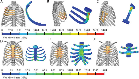
The design and von Mises stress of the implant for chest wall reconstruction. (A) In-suit rib reconstruction; (B) costal arch reconstruction; (C) vertical reconstruction; (D) whole sternum reconstruction; (E) upper segment sternum reconstruction; and (F) upper segment sternum reconstruction.
As the bridge connecting the clinical needs and 3D printing, the designing of implants plays a significant role in developing 3D-printed PEEK sternal rib implants. In the design, the clinical needs of implants must be comprehensively considered; thus, the criteria, including geometrical matching[11,51], mechanical safety[36], stable fixation[52] with residual ribs/sternum, and restoration of breath function, should be obtained while the limitation from 3D printing processes on the design of the implant should be seen as a constraint.
The in-suit rib reconstruction is one of the most typical situations, and it mainly consists of a body part, a junctional part with residual rib and/or sternum. A design framework of the in-suit rib prosthesis was reported by Kang et al.[37], as shown in Figure 2. The criterion of geometrical matching was presented in the design of the body part[53]. The common design methodology of customized implants was constructed according to the defect model from computed tomography (CT) data. However, erosion of the thoracic skeleton by tumor will result in partial bone loss or severe deformity, restricting the application of traditional design. Meanwhile, due to the complex geometric morphology characteristics and cross-section properties of natural ribs, the stair-stepping effect[54] for the direct replication model of natural ribs is significant during the printing process of FDM, which affects the surface quality and service performance[55,56]. Therefore, a new method based on the centroid trajectory of the natural rib was developed for the design of the body part of the in-suit rib prosthesis, as shown in Figure 2C[37], by which the mechanical properties of the rib prosthesis can be conveniently adjusted through the change of shape and size of cross-section. The centroid trajectory-based methodology gave more freedom in the design of the rib implant, as well as benefitted the surface quality of the PEEK prosthesis manufactured by FDM. The prosthesis needs to be stably fixed to the residual ribs or sternum. On the rib side, wire binding was employed for the fixation between rib prosthesis and natural rib, and thus in the design of rib implant, grooves are needed to prevent the wire from sliding. The prosthesis needs to be stably fixed to the residual ribs or sternum. Screw fastening was employed on the sternum side to obtain stable fixation, and countersunk holes are necessary for the screws[14].
Figure 2.
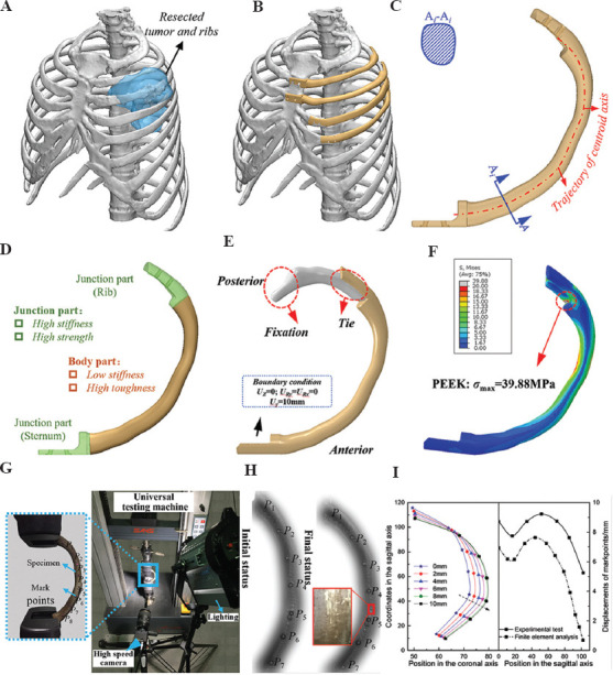
Design and evaluation of the in-suit rib prosthesis. (A) Resection plan of the tumor and ribs, (B) Scheme of the in-suit reconstruction, (C) generation of the body part of the rib prosthesis through centroid trajectory, (D) load and boundary of the FEA model of the rib and prosthesis, (E) the von Mises stress of the rib prosthesis, (F) the von Mises stress of the corresponding natural rib, (G) mechanical testing of the 3D-printed rib prosthesis, (H) the deformation pattern during of the bending test, and (I) the deformation of the in-suit rib prosthesis at different sagittal displacement (left) and a comparison of the relative displacement between experimental and FEA results.
To ensure the safety of PEEK implant, the biomechanical properties were investigated thoroughly using the finite element analysis (FEA) and experiment testing, as shown in Figure 2D and 2G. Evaluating the biomechanics of the natural rib in vivo might be difficult because of the paucity of human rib cadavers. Thus, the existing studies only evaluated the ultimate load-bearing capacity of natural rib through in vitro mechanical test[57,58]. As shown in Figure 2E and 2F, the maximum von Mises stress of an in-suit rib prosthesis is 39.88 MPa, while 143.7 MPa for natural rib at the same loading condition is shown in Figure 2D. Mechanical testing was also conducted to validate the FEA results and check the deformation and strength of the prosthesis when loading along the sagittal axis (Figure 2G), and the deformation pattern of the rib prosthesis between FEA results and mechanical testing was similar to a maximum relative error of 20% (Figure 2I). FEA results and mechanical testing showed that the PEEK in-suit rib prosthesis could withstand a sagittal displacement of 10 mm, which was close to the deformation of the human thoracic cavity, without yielding or fracture.
While the defect was located at the anterior arch of 6 – 10th ribs, a costal arch prosthesis (Figure 1B) was utilized rather than the in-suit rib prosthesis mainly because of the connection between these ribs with the sternum is realized in the costal cartilage. Wire binding was employed to fix the costal arch prosthesis with the health rib; thus, through hole is necessary for the junctions. The physical loading of the costal arch prosthesis in the human body may mainly come from the accidental impact; therefore, FEA was conducted to simulate the impact on the distal part of the costal arch prosthesis (red dashed circle in Figure 1B). The result showed that the costal arch prosthesis could bear a concentrated load of 200 N.
The vertical prosthesis is applied to reconstruct the defect close to the spine, as shown in Figure 1C, considering the surgically challenging implantation of the in-suit rib prosthesis, especially the great risk in the fixation with the spine. The same method was used to fix the vertical prosthesis with the ribs as the costal arch prosthesis. The impact from the side of the body would be the main threat to the mechanical safety of the vertical prosthesis. To simulate the mechanical performance of the prosthesis, a concentrated force of 200 N was loaded at the middle of the prosthesis in the FEA model, and the result presented the maximum von Mises stress of approximately 30 MPa, which is much lower than the yield stress of PEEK made by FDM, reported to be 60 – 84 MPa[40].
The whole sternum reconstruction was the most extreme case in the sternum-rib hybrid reconstruction, consisting of the sternum, rib, and junction parts connecting with the residual ribs. The sternum part was designed based on CT data of the thoracic cage, where unnecessary geometric features were ignored and the surface of the sternum was smoothed greatly to reduce the manufacturing difficulty while maintaining the appearance of the thorax[42]. The design method of the rib part and junction part was similar to that of the in-suit rib prosthesis. Protecting the internal organs is the major mechanical function of the whole sternum prosthesis, FEA was employed to predict the safety of the prosthesis under loading of 500 N, the maximum von Mises of the sternum prosthesis was 16 MPa which indicated the safety of the prosthesis. As for the segment sternum reconstruction, countersunk holes for the screwing fastening were introduced for the fixation with the natural sternum.
The costal cartilages connect the sternum and ribs and play an important role during the breath, and they are prolonged when inhaled and expand the thoracic cage[59]. Post-operative respiratory function after the reconstruction surgery was limited because of the much higher stiffness of PEEK compared to the costal cartilages, thus decreasing the structural elastic modulus of the PEEK rib prosthesis was the solution to the problem. A bionic design methodology through a wavy elastic structure was established by Zhang et al.[38], as shown in Figure 3. By changing the design parameters of the wavy structure, the local stiffness of the prosthesis could be adjusted. Both FEA (Figure 3C) and mechanical testing (Figure 3D and 3E) of stiffness of the wavy elastic structure with different design parameters (Figure 3A right) are shown. The results showed that the stiffness was adjusted in the range of 0.5 – 17.3 MPa (Figure 3F), which covered the elastic modulus of the costal cartilage[60]. The long-term mechanical safety of the wavy structure should be paid special attention to because it would experience tension-compression deformation for a long time. The endurance properties of the wavy structure should be further studied by mechanical testing and animal experiment before clinical application.
Figure 3.
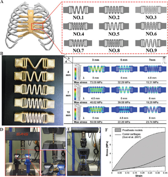
Bionic costal cartilage made of PEEK. (A) Design of wavy elastic structure; (B) 3DP PEEK wavy structure; (C) FEA results of different wavy structures; (D) bending test of the wavy structure; (E) tension test of the wavy structure; and (F) the comparison of the uniaxial stress-strain relationship between the adjustment range of the wavy structures and natural costal cartilages in tensile tests[38].
3. FDM process for 3DP PEEK implants
PEEK is a polymer material with thermoplastic properties, and its processing methods are diversified. Traditional PEEK processing methods include injection molding, compression molding, extrusion molding, and machining. The traditional method of processing and molding requires the manufacture of molds first. There are considerable advantages to the standardized manufacturing process in large quantities. However, the size and shape of the implant vary from person to person. Therefore, these processing techniques are incapable of manufacturing individualized PEEK implants. Machining is also a commonly used PEEK processing method. In general, it is necessary to combine surface treatment technology to anneal the PEEK finished product before and after machining to eliminate the influence of residual stress on the finished production. It is worth noting that when machining implants with hollow structures or curved surfaces (such as sphenoid bones or skulls) using machining methods, the amount of cutting occupies a large proportion of the raw materials, and the waste situation of materials is more serious.
In response to the limitations of traditional processing technology, 3D printing technology, as one of the most intelligent manufacturing technologies, plays a more and more prominent role[61,62]. PEEK material is also fully suitable for processing and manufacturing by 3D printing technology. 3D printing technology is also known as solid freeform fabrication, rapid prototyping, layered manufacturing, and additive manufacturing. This manufacturing technology is direct manufacturing, and a digital control mechanism centralizes its internal control through production by stacking layer by layer[63]. In addition, the inherent characteristics of 3D printing technology can also realize the preparation of controllable porous products[64]. This structure can increase the attachment of biological tissue cells, which is conducive to tissue growth[65]. 3D printed porous PEEK parts also have great potential in load-bearing and non-load-bearing applications[66]. It can be used as an implant for load-bearing bones (such as femur and tibia) and non-load-bearing bones (such as sternum and ribs). At present, FDMs are one of the most suitable 3DP methods for processing PEEK materials (Figure 4A and 4C).
Figure 4.
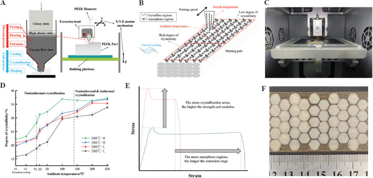
3D printing technology for PEEK implants. (A) Fused deposition modeling (FDM) process; (B) influence factors of crystallization; (C) FDM equipment; (D) crystallization regulating; (E) mechanical properties regulating; and (F) different local crystallinity structure.
3.1. Process mechanism
This technology is also called FDM[67]. This fabrication method mainly uses continuous filaments processed into corresponding diameters (Figure 4A). Moreover, after heating to a temperature close to the melting point in a liquefier, the PEEK filaments are extruded and deposited on an unfixed platform[68,69]. The extrusion head and platform of the liquefier are controlled by the digital control device of the printer, and the corresponding graphics are produced according to the preset path. For complex graphics, the printer will additionally print supporting materials to support the overhanging part of the product[70]. After the material is extruded, the subsequent cooling process will make the semi-molten extruded filament return to a solid state. At this stage, the high thermal gradient will cause residual stress in the printed product[66]. The optimal printing temperature to print PEEK filaments is from 360°C to 430°C according to melting point and denaturation temperature of PEEK material. Some 3DP equipment with high temperature (above the melting point of PEEK) print head can print PEEK filaments, which can come from Apium Corp. in Germany, Jugao Corporation in China, etc.
However, the time for this technology to process PEEK products is relatively short, and further theories and results are still needed to prove it[71]. However, there have been corresponding studies on the mechanical properties, tensile properties, and thermal processing conditions of printed PEEK products[66,40].
3.2. Crystallization and mechanical properties regulating
As a semi-crystalline polymer material, PEEK’s crystal zone proportion is called crystallinity. The mechanical, physical, and chemical properties of the crystal zone or the amorphous zone are vastly different. The crystallization properties of PEEK materials are significantly affected by the thermal history of the materials (Figure 4B). A heat insulation cover (Figure 5A-C) could be added near the 3D printing head nozzle to improve the local environment temperature near the nozzle, thus improving the uniformity of the temperature field in the process of printing to improve the ultimate strength and crystallinity of PEEK materials, and the experimental results showed that under the optimal process conditions, the maximum tensile strength could reach 75 MPa, and the maximum bending strength can reach 120 MPa (Figure 5D-F)[68]. Different ambient temperatures can obtain PEEK material parts with different crystallinity and mechanical properties in the 3D printing process. Using the printing room temperature of 140°C combined with post-printing annealing treatment (160°C for 30 min, followed by 200°C for 2 h) can improve the crystallinity and mechanical properties of PEEK material manufactured by FDM, and its tensile strength can reach 83 MPa, the compressive strength can reach up to 140 MPa and the bending strength up to 122 MPa[69]. The nozzle temperature and the printing speed can also change the crystallinity (12.40 – 18.06%) and the mechanical properties of PEEK parts after forming[66].
Figure 5.
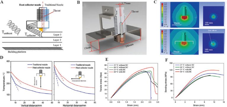
Crystallization and mechanical properties regulating. (A) Schematic diagram of the module with a heat collector module; (B) the new nozzle model; (C) the temperature distribution around the nozzle; (D) temperature profiles around the printer head; (E) tensile; and (F) bending results of printed PEEK specimens under different conditions[68].
Therefore, as shown in Table 1, by controlling the thermal conditions of 3D printing, such as ambient temperature, printing temperature, and heat treatment conditions, the crystallinity of PEEK forming can be precisely controlled, and the strength, modulus, and other properties of the material can also be controlled (Figure 4D and 4E). PEEK materials with high crystallinity (35%) can perform high strength (90 MPa tensile strength), high stiffness (4 GPa elastic modulus), and poor plasticity (15% fracture elongation); on the contrary, PEEK materials with low crystallinity (20%) show low strength (58 MPa tensile strength), low stiffness (2.65 GPa elastic modulus), and good plasticity (140% fracture elongation). Therefore, PEEK materials with different crystallinity can be formed according to the performance requirements of the prosthesis. In addition, the crystallization of PEEK materials in different areas of the same model can be controlled in real time through real-time control of 3D printing forming thermal conditions to form an integrated prosthesis with partition performance and mechanical properties regulation. Figure 4F shows the part with different local crystallinity structure.
Table 1.
The relationship between process parameters and crystallinity.
| Ambient temperature | Forced cooling | Nozzle temperature | Printing speed | Printing path | Crystallinity |
|---|---|---|---|---|---|
| ≥Tg (143°C) | Nonuse (Slow cooling) | - | Fast (Short completion time and insufficient crystallization) | - | ++++++ |
| ≥Tg | Nonuse | - | Slow (Long completion time and sufficient crystallization) | - | +++++++ |
| <Tg | Forced air cooling (rapid cooling) | Low (Small heat influence area) | Fast | Long (Sufficient cooling time) | + |
| <Tg | Forced air cooling | Low | Fast | Short (Insufficient cooling time) | ++ |
| <Tg | Forced air cooling | Low | Slow | Long | ++ |
| <Tg | Forced air cooling | Low | Slow | Short | ++ |
| <Tg | Forced air cooling | High (Big heat influence area) | Fast | Long | ++ |
| <Tg | Forced air cooling | High | Fast | Short | +++ |
| <Tg | Forced air cooling | High | Slow | Long | +++ |
| <Tg | Forced air cooling | High | Slow | Short | ++++ |
| <Tg | Nonuse | Low | Fast | Long | +++ |
| <Tg | Nonuse | Low | Fast | Short | ++++ |
| <Tg | Nonuse | Low | Slow | Long | ++++ |
| <Tg | Nonuse | Low | Slow | Short | ++++ |
| <Tg | Nonuse | High | Fast | Long | ++++ |
| <Tg | Nonuse | High | Fast | Short | +++++ |
| <Tg | Nonuse | High | Slow | Long | +++++ |
| <Tg | Nonuse | High | Slow | Short | ++++++ |
3.3. Process parameters of FDM and anisotropy of PEEK material
The key technical process parameters of FDM can change the mechanical properties of PEEK materials. Among them, the printing angle and the path should be especially considered for the influence of the anisotropy of fabrication, which affects the overall performance and ability to apply the manufactured PEEK materials. Experimental results show that the additive manufactured PEEK has different anisotropy with different layer thickness and printing angle, and the PEEK specimens with the layer thickness of 0.3 mm and the printing angle of 0°/90° alternately have the best mechanical properties, with the maximum bending strength of 56.1 MPa and the maximum tensile strength of 56.6 MPa (Figure 6A and B)[70]. The printing speed and filling rate can also affect the properties and the microstructure of PEEK material manufactured by the FDM technology. Experimental results show that under the layer thickness of 0.2 mm, the printing speed of 60 mm/s, and the filling speed rate of 40%, the PEEK sample has good comprehensive mechanical properties, with the tensile strength of 40 MPa, tensile fracture elongation of 14.3%, bending strength of 68.2 MPa, and impact strength of 101.2 kJ/m2 (Figure 6C-E)[71].
Figure 6.
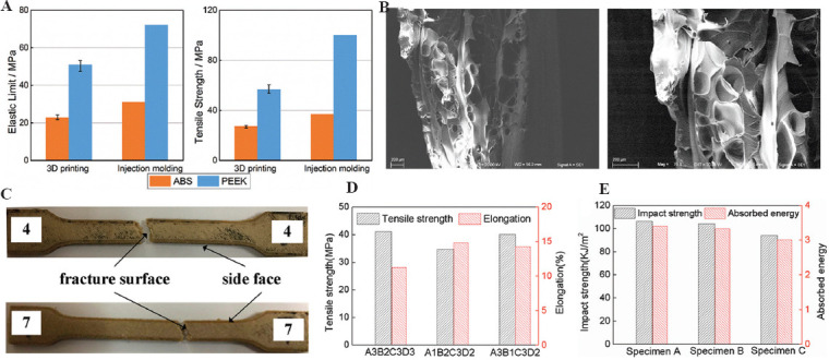
Process parameters of FDM and the mechanical properties of PEEK materials. (A) Tensile property of PEEK; (B) SEM images of fracture cross-sections of PEEK; (C) fractured tensile specimens; (D) comparison of tensile properties for different printing parameters; and (E) impact strength and absorbed energy[70,71].
Therefore, because FDM 3D printing method adopts the method of line-line bonding and layer-layer deposition, the interface problem between lines will cause the mechanical properties (especially the fracture elongation) along the printing line to be higher than in other directions. In addition, the extrusion mobile forming will make the polymer chain of the polymer material align in a highly oriented direction along the printing path, which will greatly improve the tensile and extension performance of the material in this direction, thus resulting in 3D anisotropy of additive manufactured PEEK prosthesis. The highest mechanical properties of the printing direction may approach injection molding, while those of the weakest direction may be less than half of that[42]. Therefore, for the large size prosthesis model, it is critical to adopt appropriate placement through stress analysis and performance demand analysis to ensure that the anisotropy conforms to the biomechanical environment of the implants.
3.4. Manufacturing process of personalized sternal rib implants
Sternal rib implants can accurately repair the sternal defect of patients to ensure sufficient mechanical, biological safety and long-term reliability. To reduce the loss of respiratory function after implant surgery, the designed thoracic rib model can be divided into four functional areas for different manufacturing processes (Figure 7).
Figure 7.
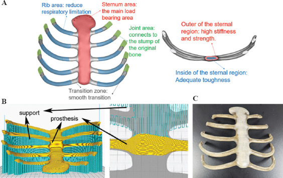
The manufacturing process of personalized sternal rib implants. (A) Performance requirement analysis of sternal prosthesis. (B) Printing path planning and a close-up of the support structures. (C) 3D-printed PEEK sternal rib implants.
Sternum area (high stress and high deformation area): Sternum is one of the most important bones to bear the load and protect viscera, which requires high stiffness and enough strength. In addition, given the cyclic deformation caused by respiration, requires sternum area in the implants also needs a certain toughness. Therefore, for the 3D printing process, one of the feasible schemes is that the outer layer of the sternal region has a very high crystallinity (≥35%) with a thickness of about 3 mm, while the inner region has a very low crystallinity (≤25%).
Rib area (high deformation area): Costal cartilage that exists in the human body can generate the right amount of deformation in human breathing. Therefore, to get the lowest modulus possible, the 3D printing process in the rib area should be designed to get a very low crystallinity (≤25%) for the implants.
Joint area (wear resistance, connection area): This area needs a good hardness and abrasion resistance to guarantee long-term connection reliability, the crystallinity in this area can be designed to be 30 ± 2% by the 3D printing process with moderate temperature conditions.
Transition region: To avoid stress concentration, the transition region should be manufactured to get an appropriate crystallinity variation between different contiguous crystallinity areas.
4. Application of 3DP PEEK implants for personalized chest wall reconstruction
4.1. Large size individualized PEEK implants for ribs defects
In general, the 3DP PEEK implants for ribs reconstruction can be divided into three categories according to the shape of the implants, including the horizontal type (Figure 8A), E type (Figure 8B), and vertical type (Figure 8C). The category of implants can be better used in clinical practice. As for the implants for ribs reconstruction, the strength of the joint area is key point in the manufacturing process. The 3DP PEEK implant is bound with the residual ribs using the titanium wire and fixed with the sternum using two titanium screws (Figure 8A). Thus, the 3DP PEEK implants are fixed through a rigid connection. FDM process in the joint area was used here to fabricate the joint area of 3DP PEEK implants with enough hardness and strength. In addition, the connector structure is another factor affecting the stability of implants. The implants cannot be fixed in a symmetric position due to the irregularity of the costal arch, making for the instability of the implant after surgery. Thus, the implant is designed as a massive structure (E type), possessing multiple junctions with the residual ribs and upper ribs adjacent to the defect. The E-type implant was fixed with the residual ribs and the upper rib adjacent to the defect (Figure 8B). The multiple junctions can confirm the stability of the implant after surgery. The vertical type implants are used to repair the chest wall defects adjacent to the spine because it is difficult to fix the implants with the spine in accordance with the anatomic structure. In this case, the connector of implants is designed as a flat and semi-arc shape to adhere to the rib tightly, and the implant is bound with the upper and lower ribs adjacent to the defect using titanium wire (Figure 8C). At last, a pericardial patch was suspended under the 3DP PEEK implants to close the thorax. It is necessary to use the biological patch to isolate the PEEK implants from the lung because the hydrophobicity of PEEK materials can prevent the adhesion of soft tissues. In addition, the patch was fixed with the 3DP PEEK implants using the sutures, and no motion happened between the PEEK implants and patch. In our hospital, 49 patients received ribs reconstruction using 3DP PEEK implants, including 34 of horizontal type, six of vertical type, and nine of E type. The main chest wall diseases were primary and metastatic tumor. The average chest wall defect size was 220.0 ± 120.5 cm2 (64– 700 cm2).
Figure 8.
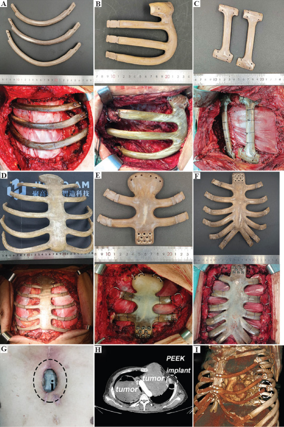
The 3DP PEEK implants of horizontal type (A), E type and (B), vertical type and (C), corresponding chest wall reconstruction surgery images. The 3DP PEEK implants for whole sternum (D), manubrium sterni, and (E) mesosternum (F) defect, and corresponding chest wall reconstruction surgery images. The incision ulcer and 3DP PEEK implant exposure. (G) After the surgery (the black circle point out the PEEK implant). The displacement of 3DP PEEK implant in the rib (H and I) residues (the white circle points out the displacement part).
4.2. Large size individualized 3DP PEEK implants for sternum defects
We classified sternal defects into three categories according to the defect site, including the whole sternum, manubrium sterni, and mesosternum defect. Furthermore, we designed and fabricated the individualized 3DP PEEK implants according to the sternum defect types (Figure 8D-F). Herein, reliable mechanical links are key to implant stability. For the whole sternum implant, we usually use wires to bind the implant with residual ribs embracingly (Figure 8D). The side through-hole must be reserved in the connection of the implant for embracing binding. Based on our experience, the 3DP PEEK implant should be secured below the residual ribs to prevent the implant from pushing against the skin and causing ulcers. For the manubrium sterni and mesosternum implants, we usually use eight titanium screws to fix the implant with the residual sternum (Figure 8E and F). It is worth mentioning that we always use two wires to bind the implant with the clavicle. Although this fixation does not restore motion of the sternoclavicular joint, it is stable enough in the body during the following up period. A pericardial patch was also suspended under the 3DP PEEK implants to close the thorax. In our hospital, 65 patients received sternum reconstruction using 3DP PEEK implants, including 11 whole sternum implants, 34 manubrium sterni, and 20 mesosternum implants. The average weight of the 3DP PEEK sternum implant was 107.4 ± 33.6 g. The main chest wall diseases were primary tumor and infection. The average chest wall defect size was 140.9 ± 101.5 cm2 (range, 64– 900 cm2).
4.3. Pulmonary function assessment and adverse reactions of implants
A healthy person breathes about 20 times/min. That is to say, and the thorax moves more than 10 million times in 1 year. The titanium plates are the traditional implants for chest wall reconstruction. However, the mechanical property of titanium is much greater than that of cortical bone or costicartilage[72]. The motion of thorax is restricted after using the titanium implants. The forced vital capacity (FVC) of patients is reduced by more than 30% after traditional surgery[73-76]. The pulmonary function of patients decreased significantly if the mechanical mismatch implants were used in surgery. Thus, the FDM process with low crystallinity (≤25%) was used in the middle segment of 3DP PEEK implant to make it flexible.
To test the effect of 3DP PEEK implant to pulmonary function, each patient received pulmonary function examination before and after surgery. The pulmonary function of each patient was tested and compared between pre-operative (1 week before the operation) and post-operative (3 months after the operation) groups. For the patients receiving 3DP ribs PEEK implants, pulmonary function results show that pre-operative and post-operative FVC ranged from 2.90 ± 0.66 L to 2.53 ± 0.80 L (P < 0.001), FEV1/FVC ranged from 82.4% ± 5.7% to 81.8% ± 6.7% (P > 0.05), MVV ranged from 83.73 ± 21.15 L/min to 83.19 ± 28.4 L/min (P < 0.49), and partial pressure of oxygen ranged from 86.1 ± 10.7 mmHg to 80.4 ± 9.2 mmHg (P > 0.05). The mean reduction of FVC in these patients after surgery was 0.36 ± 0.25 L, which represents 12.4% of the pre-operative FVC value. For the patients receiving 3DP sternum PEEK implants, pulmonary function results show that pre-operative and post-operative FVC ranged from 2.65 ± 0.72 L to 2.23 ± 0.55 L (P < 0.001), FEV1/FVC ranged from 82.4% ± 6.7% to 87.5% ± 9.3% (P > 0.05), MVV ranged from 76.38 ± 24.61 L/min to 71.9 ± 24.4 L/min (P > 0.05), and partial pressure of oxygen ranged from 84.1 ± 9.7 mmHg to 80.2 ± 10.2 mmHg (P > 0.05). The mean reduction of FVC in these patients after surgery was 0.44 ± 0.25 L, which represents 16.6% of the pre-operative FVC value. As compared with the titanium plates, 3DP PEEK implants may help the patients to preserve more pulmonary function.
In the follow-up period, six patients suffered from incision ulcer 1 year after the surgery (Figure 8G), which may be related to the hydrophobic surface of PEEK material. Three patients received the first surgery to remove the exposed partial PEEK implant, then received a second pectoralis major myocutaneous flap transfer surgery 2 weeks later. The displacement of the 3DP PEEK implant happened in a patient due to the recurrence of tumor in situ and erosion in the rib residue (Figure 8H and I).
5. Interface modification and composite print of PEEK implant for clinical need
The most common and serious implant-related complication in the follow-up period is incision ulcer, accounting for about 5.3% (6/114). These patients have to receive a second surgery to remove the implants and transfer a myocutaneous flap to cover the chest wall defects until 6 – 9 months after the first surgery. Some reasons can be summarized as follows. First, the hydrophobic surface of PEEK materials inhibited protein deposition and tissue adhesion with the implant. There may be relative friction between the soft tissue and implant that may cause the incision ulcer in the follow-up visit. For another thing, due to the wide excision of chest wall tumor, the lack of muscle coverage is also the main cause of post-operative incision ulcer. Thus, enhancing the soft-tissue integration with the 3DP PEEK implant is the main method to reduce implant-related complications. We have developed surface amination grafting and sulfuric acid etching methods to increase the hydrophilic of 3DP PEEK implants[45-46].
3D PEEK lattice structures are fabricated by the previous FDM system to observe the soft-tissue ingrowth (Figure 9A). The whole FDM process is same as that for clinical implants. Then, two modified methods are used respectively to improve the hydrophilic of PEEK interfaces. To obtain uniform microporous architectures, a sulfonation treatment strategy is developed by fully immersing the 3DP PEEK scaffolds into concentrated sulfuric acid (95.0 – 98.0%) for 30 – 45 s (Figure 9A). The micropores (Figure 9B) with an average size of 0.19 ± 0.07 mm show little effect on the mechanical property of the whole PEEK implant (Figure 9C and D). Furthermore, the micropores on the PEEK implant significantly improve the cellular attachment, spreading, and proliferation, which can also facilitate the tight adhesion of newly regenerated soft tissues to the PEEK implant (Figure 9E-G).
Figure 9.
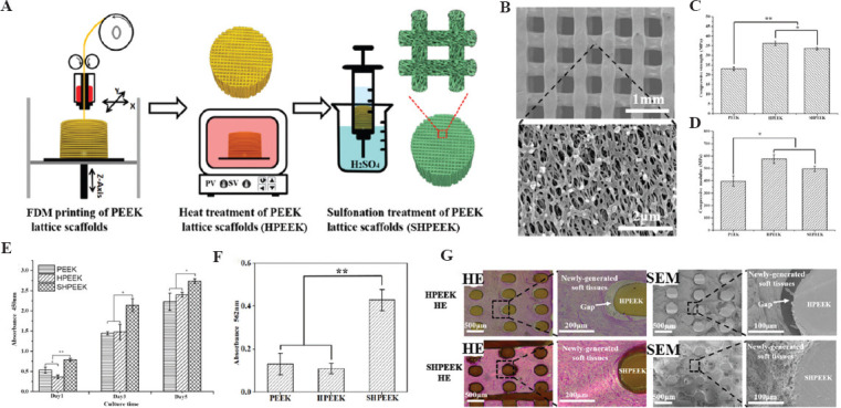
Schematic diagram of the preparation process to create the microporous architectures in the FDM PEEK scaffolds (A); SEM images of SHPEEK scaffolds with a sulfonation processing time of 30 s (B); the comparison of compressive strength (C) and compressive modulus (D) in FDM PEEK, HPEEK, and SHPEEK scaffolds; the comparison of cellular proliferation in FDM PEEK, HPEEK, and SHPEEK scaffolds using CCK-8 method (E); the comparison of deposited calcified nodules in FDM PEEK, HPEEK, and SHPEEK scaffolds (F); HE staining and SEM images of soft-tissue ingrowth into the FDM HPEEK and SHPEEK scaffolds in vivo for 2 weeks (G) (*P < 0.05 and **P < 0.01)[45].
To obtain the uniform amidogen on the interface of PEEK, O2 plasma and (3-aminopropyl) triethoxysilane are successively coated on the 3DP PEEK scaffolds (Figure 10A-C). The amidogen PEEK (NPEEK) significantly improves the cellular adhesion and migration of the fibroblasts (L929 cells) (Figure 10D and E). Furthermore, soft-tissue ingrowth occurs more and faster in the NPEEK interface after the NPEEK scaffold is embedded in the chest wall of rabbit (Figure 10F). In the animal experiment, a clathrate PEEK implant is fabricated to mimic the real sternal implant (Figure 10G). The surgical procedures to reconstruct the chest wall defects of rabbits are the same as the clinical surgery for humans. The PEEK implant with amidogen interface can remarkably reduce the healing time and incision complications (Figure 10H and I). The micropores and amidogen on the interface of PEEK implants proved the effectiveness of soft-tissue ingrowth, as reported in the previous studies.
Figure 10.
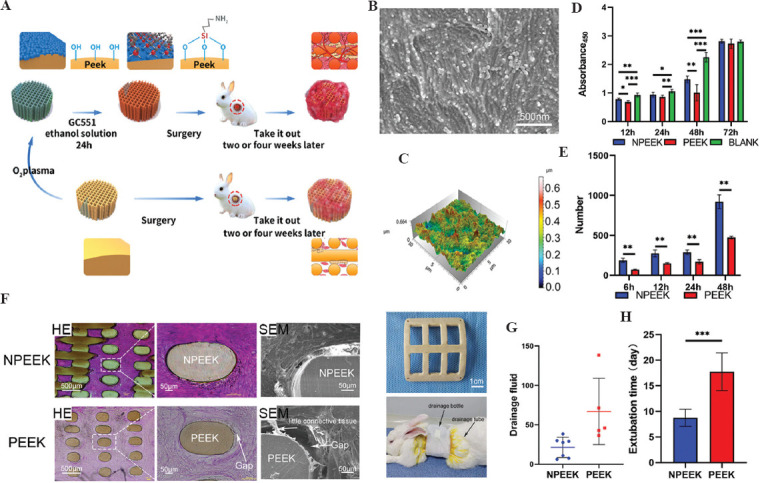
Schematic diagram of FDM PEEK implant modification and animal experiment results (A); SEM images of the interface on amidogen PEEK (B); three-dimensional images of the interface on amidogen PEEK (C); the comparison of cellular proliferation in FDM PEEK, NPEEK scaffolds, and blank materials using CCK-8 method (D); the comparison of cell migration on NPEEK and PEEK interfaces using wound healing assay (E); HE staining and SEM images of soft-tissue ingrowth into the FDM PEEK and NPEEK scaffolds in vivo for 2 weeks (F); the clathrate PEEK or NPEEK implants and the rabbit after chest wall reconstruction surgery (G); the comparison of drainage fluid (H) and extubation time (I) after chest wall reconstruction surgery in FDM PEEK and NPEEK groups (*P < 0.05, **P < 0.01 and ***P < 0.001)[46].
It is worth mentioning that the displacement and rupture of the 3DP PEEK implant after surgery infrequently happened in the follow-up period because sternum and ribs are the non-load-bearing bone and the implants do not have to carry too much load. As an orthopedic implant, enhancing the osseointegration can increase the stability of the implants in vivo. Thus, we further manufacture 3DP PEEK composite scaffolds with hydroxyapatite (HA) or calcium silicate (CS) contents in gradient through FDM 3D printing techniques (Figure 11A)[47-49]. The PEEK (50 mm) and additives (HA or CS powder) (Figure 11B and C) are first mixed with a mass ratio (PEEK: HA = 8:2; PEEK: CS = 6:4). Then, the filaments with a diameter of 1.75 mm are extruded using the PEEK and additives mixture in a twin-screw extruder. The filaments are further used to fabricate tetragonal scaffold samples (length, width, and thickness of 10 mm) through FDM process. The PEEK and additives (HA or CS particles) are uniformly distributed in the filaments and the scaffold samples (Figure 11D). The modulus of the PEEK/HA scaffold increase relative to the rise of HA content, while the strength and failure strain concomitantly decreased. The elastic modulus of the PEEK/HA or PEEK/CS scaffolds can be close to the values of natural bone by regulating HA/CS content and porosity (Figure 11E-H). The PEEK/HA or PEEK/CS scaffolds can significantly improve the MC3T3-E1 cell attachment and mineralization (Figure 11I-K), and the structural design and mechanical properties are the main regulatory factors for bone tissue engineering.
Figure 11.
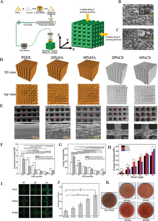
Schematic diagram of the preparation processes of PEEK/additives composites and FDM technology (A); the SEM images of PEEK granular material (B) and HA powders material (C) (white bar, 100 mm; yellow bar, 50 mm); geometry images of PEEK/HA and PEEK/CS scaffolds under micro-CT (D); SEM images of PEEK/HA and PEEK/CS scaffolds (E); the comparison of compressive modulus (F) and compressive strength (G) in PEEK/HA scaffolds with different pore sizes; the comparison of compressive modulus of the PEEK/CS scaffolds with different CS content and raster angles (H); the comparison of cellular proliferation in PEEK/HA scaffolds with different HA content (white bar, 400 mm); the comparison of alizarin red staining (J) and Alizarin red staining (K) of MC3T3-E1cells on the PEEK/HA scaffolds with different HA content[47-49].
6. Future perspectives
The 3DP PEEK implants have proven the feasibility of reconstructing chest wall defects. A total of 114 clinical cases in more than 40 hospitals in China have received chest wall reconstruction using the 3DP PEEK implants. It is critical to forming a stable team, including engineers, scientists, surgeons, and clinical research associates. The design methods, manufacturing process, and even implant surgery programs have improved with increased clinical cases. In the whole process, engineers and surgeons must work together for every special case. The surgical procedure must be recorded in detail, and the patients should be followed up periodically after surgery. Except for the efficacy of 3DP PEEK implant, it is critical to record the implant-related complication. The next modification of manufacturing process is originated from the main implant-related complication. The concept of biofabrication originated from clinical practice and was finally applied to clinical practice.
The 3DP PEEK implants need to be approved by the Food and Drug Administration or National Medical Products Administration. Personalized implants are an important development trend in future medicine, but they also bring new challenges to the regulatory authorities. The qualification rate of conventional implants can be tested by sampling, but this method is not suitable for personalized implants. It is difficult to test the physical and chemical properties of personalized implants because all implants are different, such as shape, and mechanical properties. The regulators cannot test the properties of every personalized implant in clinical practice. This is why there are no commercialized personalized implants in clinical practice. Although some implants are fabricated by 3DP technology, they are still classified by product size or materials: Standardized implants and not personalized implants. 3DP technology can save on raw materials and is more suitable for implants with complex internal structures. Thus, many acetabular cups with specific sizes are made using 3DP technology globally, but these acetabular cups cannot be regarded as personalized implants. Possibly, testing of implants could be replaced by supervising production lines or equipment of 3DP implants in the future. Adjusting regulatory policies and improving production technology can bring new vitality to the industrialization of 3DP personalized implants.
7. Conclusion
3DP PEEK implants are the ideal material for repair of orthopedic defects. It is necessary to perform finite element analysis for every implant to achieve anatomic and mechanical match. The FDM technology is a suitable method for manufacturing PEEK implants. Up to now, the thoracic surgeons have used 114 personalized 3DP PEEK implants to reconstruct the chest wall defect and further established the surgical standards of the implants in Chinese clinical guidelines.
Acknowledgments
We thank Feiyang Yin for editing the manuscript.
Conflict of interest
No conflicts of interest were reported by all authors.
Author contributions
Conceptualization: Lijun Huang, Dichen Li, and Tao Jiang
Investigation: Lei Wang, Xiaolong Yan, and Changquan Shi
Writing – original draft: Lei Wang, Chuncheng Yang, and Changning Sun
Writing – review and editing: Jiangkang He and Chaozong Liu
Funding
The work was supported by National Key R&D Program of China (2018YFE0207900), Lingyun Program of Air Force Medical University (2019cyjhwl), Top-Notch Project of Medical Science and Technology for Youth Cultivation of the Army (18QNP028), Clinical Development Innovation Fund of Air Force Medical University(2021XB024), Zhufeng Program of Air Force Medical University (2019rcfcyxl), Key R&D Program of Guangdong Province (2018B090906001), and the National Natural Science Foundation of China (51835010).
References
- 1.Ambrosi A, Pumera M. 3D-printing technologies for electrochemical applications. Chem Soc Rev. 2016;45:2740–55. doi: 10.1039/c5cs00714c. https://doi.org/10.1039/c5cs00714c. [DOI] [PubMed] [Google Scholar]
- 2.Hu G, Kang J, Ng LW, et al. Functional inks and printing of two-dimensional materials. Chem Soc Rev. 2018;47:3265–300. doi: 10.1039/c8cs00084k. https://doi.org/10.1039/c8cs00084k. [DOI] [PubMed] [Google Scholar]
- 3.Layani M, Wang X, Magdassi S. Novel Materials for 3D Printing by Photopolymerization. Adv Mater. 2018;30:e1706344. doi: 10.1002/adma.201706344. https://doi.org/10.1002/adma.201706344. [DOI] [PubMed] [Google Scholar]
- 4.Hirt L, Reiser A, Spolenak R, et al. Additive manufacturing of metal structures at the micrometer scale. Adv Mater. 2017;29:1604211. doi: 10.1002/adma.201604211. https://doi.org/10.1002/adma.201604211. [DOI] [PubMed] [Google Scholar]
- 5.Liaw CY, Guvendiren M. Current and emerging applications of 3D printing in medicine. Biofabrication. 2017;9:024102. doi: 10.1088/1758-5090/aa7279. https://doi.org/10.1088/1758-5090/aa7279. [DOI] [PubMed] [Google Scholar]
- 6.Martelli N, Serrano C, van den Brink H, et al. Advantages and disadvantages of 3-dimensional printing in surgery:A systematic review. Surgery. 2016;159:1485–500. doi: 10.1016/j.surg.2015.12.017. https://doi.org/10.1016/j.surg.2015.12.017. [DOI] [PubMed] [Google Scholar]
- 7.Khorsandi D, Fahimipour A, Abasian P, et al. 3D and 4D printing in dentistry and maxillofacial surgery:Printing techniques, materials, and applications. Acta Biomater. 2021;122:26–49. doi: 10.1016/j.actbio.2020.12.044. https://doi.org/10.1016/j.actbio.2020.12.044. [DOI] [PubMed] [Google Scholar]
- 8.Burnard JL, Parr WC, Choy WJ, et al. 3D-printed spine surgery implants:A systematic review of the efficacy and clinical safety profile of patient-specific and off-the-shelf devices. Eur Spine J. 2020;29:1248–60. doi: 10.1007/s00586-019-06236-2. https://doi.org/10.1007/s00586-019-06236-2. [DOI] [PubMed] [Google Scholar]
- 9.Melville JC, Manis CS, Shum JW, et al. Single-Unit 3D-Printed Titanium Reconstruction Plate for Maxillary Reconstruction:The Evolution of Surgical Reconstruction for Maxillary Defects-A Case Report and Review of Current Techniques. J Oral Maxillofac Surg. 2019;77:874. doi: 10.1016/j.joms.2018.11.030. e1–13. https://doi.org/10.1016/j.joms.2018.11.030. [DOI] [PubMed] [Google Scholar]
- 10.Kamel MK, Cheng A, Vaughan B, et al. Sternal reconstruction using customized 3D-printed titanium implants. Ann Thorac Surg. 2020;109:e411–4. doi: 10.1016/j.athoracsur.2019.09.087. https://doi.org/10.1016/j.athoracsur.2019.09.087. [DOI] [PubMed] [Google Scholar]
- 11.Wang L, Cao T, Li X, et al. Three-dimensional printing titanium ribs for complex reconstruction after extensive posterolateral chest wall resection in lung cancer. J Thorac Cardiovasc Surg. 2016;152:e5–7. doi: 10.1016/j.jtcvs.2016.02.064. https://doi.org/10.1016/j.jtcvs.2016.02.064. [DOI] [PubMed] [Google Scholar]
- 12.Anderson LA, Christie M, Blackburn BE, et al. 3D-printed titanium metaphyseal cones in revision total knee arthroplasty with cemented and cementless stems. Bone Joint J. 2021;103-b 6(Suppl A):150–7. doi: 10.1302/0301-620X.103B6.BJJ-2020-2504.R1. https://doi.org/10.1302/0301-620x.103b6.Bjj-2020-2504.R1. [DOI] [PubMed] [Google Scholar]
- 13.Moradiellos J, Amor S, Córdoba M, et al. Functional chest wall reconstruction with a biomechanical three-dimensionally printed implant. Ann Thorac Surg. 2017;103:e389–91. doi: 10.1016/j.athoracsur.2016.11.048. https://doi.org/10.1016/j.athoracsur.2016.11.048. [DOI] [PubMed] [Google Scholar]
- 14.Wang L, Huang L, Li X, et al. Three-dimensional printing PEEK implant:A novel choice for the reconstruction of chest wall defect. Ann Thorac Surg. 2019;107:921–8. doi: 10.1016/j.athoracsur.2018.09.044. https://doi.org/10.1016/j.athoracsur.2018.09.044. [DOI] [PubMed] [Google Scholar]
- 15.Aragon J, Perez Mendez I. Dynamic 3D printed titanium copy prosthesis:A novel design for large chest wall resection and reconstruction. J Thorac Dis. 2016;8:E385–9. doi: 10.21037/jtd.2016.03.94. https://doi.org/10.21037/jtd.2016.03.94. [DOI] [PMC free article] [PubMed] [Google Scholar]
- 16.Kurtz SM. An overview of PEEK biomaterials. In: PEEK Biomaterials Handbook. 2nd ed. Ch. 1. Norwich, NY: William Andrew Publishing; 2019. pp. 3–9. [Google Scholar]
- 17.Bessard E, De Almeida O, Bernhart G. Unified isothermal and non-isothermal modelling of neat PEEK crystallization. J Therm Anal Calorim. 2014;115:1669–78. https://doi.org/10.1007/s10973-013-3308-8. [Google Scholar]
- 18.Katti KS. Biomaterials in total joint replacement. Colloids Surf B Biointerfaces. 2004;39:133–42. doi: 10.1016/j.colsurfb.2003.12.002. https://doi.org/10.1016/j.colsurfb.2003.12.002. [DOI] [PubMed] [Google Scholar]
- 19.Stober EJ, Seferis JC, Keenan JD. Characterization and exposure of polyetheretherketone (PEEK) to fluid environments. Polymer. 1984;25:1845–52. https://doi.org/10.1016/0032-3861(84)90260-X. [Google Scholar]
- 20.Boinard E, Pethrick RA, MacFarlane CJ. The influence of thermal history on the dynamic mechanical and dielectric studies of polyetheretherketone exposed to water and brine. Polymer. 2000;41:1063–76. https://doi.org/10.1016/S0032-3861(99)00259-1. [Google Scholar]
- 21.Bishop MT, Karasz FE, Russo PS, et al. Solubility and properties of a poly(aryl ether ketone) in strong acids. Macromolecules. 1985;18:86–93. https://doi.org/10.1021/ma00143a014. [Google Scholar]
- 22.Li HM, Fouracre RA, Given MJ, et al. The effects on polyetheretherketone and polyethersulfone of electron and/spl gamma/irradiation. IEEE Trans Dielectr Electr Insul. 1999;6:295–303. https://doi.org/10.1109/94.775614. [Google Scholar]
- 23.Kurtz SM, Devine JN. PEEK biomaterials in trauma, orthopedic, and spinal implants. Biomaterials. 2007;28:4845–69. doi: 10.1016/j.biomaterials.2007.07.013. https://doi.org/10.1016/j.biomaterials.2007.07.013. [DOI] [PMC free article] [PubMed] [Google Scholar]
- 24.Ouyang L, Chen M, Wang D, et al. Nano Textured PEEK Surface for Enhanced Osseointegration. ACS Biomater Sci Eng. 2019;5:1279–89. doi: 10.1021/acsbiomaterials.8b01425. https://doi.org/10.1021/acsbiomaterials.8b01425. [DOI] [PubMed] [Google Scholar]
- 25.Han X, Yang D, Yang C, et al. Carbon fiber reinforced PEEK composites based on 3D-printing technology for orthopedic and dental applications. J Clin Med. 2019;8:240. doi: 10.3390/jcm8020240. https://doi.org/10.3390/jcm8020240. [DOI] [PMC free article] [PubMed] [Google Scholar]
- 26.Katzer A, Marquardt H, Westendorf J, et al. Polyetheretherketone—cytotoxicity and mutagenicity in vitro. Biomaterials. 2002;23:1749–59. doi: 10.1016/s0142-9612(01)00300-3. https://doi.org/10.1016/S0142-9612(01)00300-3. [DOI] [PubMed] [Google Scholar]
- 27.Toth JM, Wang M, Estes BT, et al. Polyetheretherketone as a biomaterial for spinal applications. Biomaterials. 2006;27:324–34. doi: 10.1016/j.biomaterials.2005.07.011. https://doi.org/10.1016/j.biomaterials.2005.07.011. [DOI] [PubMed] [Google Scholar]
- 28.Stratton-Powell AA, Pasko KM, Brockett CL, et al. The biologic response to polyetheretherketone (PEEK) wear particles in total joint replacement:A systematic review. Clin Orthop Relat Res. 2016;474:2394–404. doi: 10.1007/s11999-016-4976-z. https://doi.org/10.1007/s11999-016-4976-z. [DOI] [PMC free article] [PubMed] [Google Scholar]
- 29.Wang L, Liu X, Jiang T, et al. Three-dimensional printed polyether-ether-ketone implant for extensive chest wall reconstruction:A case report. Thorac Cancer. 2020;11:2709–12. doi: 10.1111/1759-7714.13560. https://doi.org/10.1111/1759-7714.13560. [DOI] [PMC free article] [PubMed] [Google Scholar]
- 30.Lethaus B, Ter Laak MP, Laeven P, et al. A treatment algorithm for patients with large skull bone defects and first results. J Craniomaxillofac Surg. 2011;39:435–40. doi: 10.1016/j.jcms.2010.10.003. https://doi.org/10.1016/j.jcms.2010.10.003. [DOI] [PubMed] [Google Scholar]
- 31.Kim MM, Boahene KD, Byrne PJ. Use of customized polyetheretherketone (PEEK) implants in the reconstruction of complex maxillofacial defects. Arch Facial Plast Surg. 2009;11:53–7. doi: 10.1001/archfaci.11.1.53. https://doi.org/10.1001/archfaci.11.1.53. [DOI] [PubMed] [Google Scholar]
- 32.Najeeb S, Zafar MS, Khurshid Z, et al. Applications of polyetheretherketone (PEEK) in oral implantology and prosthodontics. J Prosthodont Res. 2016;60:12–9. doi: 10.1016/j.jpor.2015.10.001. https://doi.org/10.1016/j.jpor.2015.10.001. [DOI] [PubMed] [Google Scholar]
- 33.Panayotov IV, Orti V, Cuisinier F, et al. Polyetheretherketone (PEEK) for medical applications. J Mater Sci Mater Med. 2016;27:118. doi: 10.1007/s10856-016-5731-4. https://doi.org/10.1007/s10856-016-5731-4. [DOI] [PubMed] [Google Scholar]
- 34.Seaman S, Kerezoudis P, Bydon M, et al. Titanium vs. polyetheretherketone (PEEK) interbody fusion:Meta-analysis and review of the literature. J Clin Neurosci. 2017;44:23–9. doi: 10.1016/j.jocn.2017.06.062. https://doi.org/10.1016/j.jocn.2017.06.062. [DOI] [PubMed] [Google Scholar]
- 35.Zanjanijam AR, Major I, Lyons JG, et al. Fused filament fabrication of PEEK:A review of process-structure-property relationships. Polymers (Basel) 2020;12:1665. doi: 10.3390/polym12081665. https://doi.org/10.3390/polym12081665. [DOI] [PMC free article] [PubMed] [Google Scholar]
- 36.Sun C, Jin Z, Wang L, et al. In 8th WACBE World Congress on Bioengineering 2017 [Google Scholar]
- 37.Kang J, Wang L, Yang C, et al. Custom design and biomechanical analysis of 3D-printed PEEK rib prostheses. Biomech Model Mechanobiol. 2018;17:1083–92. doi: 10.1007/s10237-018-1015-x. https://doi.org/10.1007/s10237-018-1015-x. [DOI] [PubMed] [Google Scholar]
- 38.Zhang C, Wang L, Kang J, et al. Bionic design and verification of 3D printed PEEK costal cartilage prosthesis. J Mech Behav Biomed Mater. 2020;103:103561. doi: 10.1016/j.jmbbm.2019.103561. https://doi.org/10.1016/j.jmbbm.2019.103561. [DOI] [PubMed] [Google Scholar]
- 39.Yang C, Wang B, Li D, et al. Modelling and characterisation for the responsive performance of CF/PLA and CF/PEEK smart materials fabricated by 4D printing. Virtual Phys Prototyp. 2017;12:69–76. https://doi.org/10.1080/17452759.2016.1265992. [Google Scholar]
- 40.Yang C, Tian X, Li D, et al. Influence of thermal processing conditions in 3D printing on the crystallinity and mechanical properties of PEEK material. J Mater Process Technol. 2017;248:1–7. https://doi.org/10.1016/j.jmatprotec.2017.04.027. [Google Scholar]
- 41.Yang C, Tian X, Liu T, et al. 3D printing for continuous fiber reinforced thermoplastic composites:Mechanism and performance. Rapid Prototyp J. 2017;23:209–15. https://doi.org/10.1108/rpj-08-2015-0098. [Google Scholar]
- 42.Li D, Yang C, Kang J, et al. Precision design and control-performance manufacturing research of large-size individualized PEEK implants. J Mech. 2018;54:121–5. https://doi.org/10.3901/JME.2018.23.121. [Google Scholar]
- 43.Wang L, Li J, Zhong D. Chinese expert consensus on chest wall tumor resection and chest wall reconstruction (version 2018) Chin J Clin Thorac Cardiovasc Surg. 2019;26:1–7. https://doi.org/10.7507/1007-4848.201809058. [Google Scholar]
- 44.Wang L, Yan X, Zhao J, et al. Expert consensus on resection of chest wall tumors and chest wall reconstruction. Transl Lung Cancer Res. 2021;10:4057–83. doi: 10.21037/tlcr-21-935. https://doi.org/10.21037/tlcr-21-935. [DOI] [PMC free article] [PubMed] [Google Scholar]
- 45.Su Y, He J, Jiang N, et al. Additively-manufactured poly-ether-ether-ketone (PEEK) lattice scaffolds with uniform microporous architectures for enhanced cellular response and soft tissue adhesion. Mater Des. 2020;191:108671. https://doi.org/10.1016/j.matdes.2020.108671. [Google Scholar]
- 46.Liu X, Huang L, Zhang H, et al. Facile Amidogen Bio?Activation Method Can Boost the Soft Tissue Integration on 3D Printed Poly–Ether–Ether–Ketone Interface. Adv Mater Interfaces. 2021;8:2100547. https://doi.org/10.1002/admi.202100547. [Google Scholar]
- 47.Zheng J, Kang J, Sun C, et al. Effects of printing path and material components on mechanical properties of 3D-printed polyether-ether-ketone/hydroxyapatite composites. J Mech Behav Biomed Mater. 2021;118:104475. doi: 10.1016/j.jmbbm.2021.104475. https://doi.org/10.1016/j.jmbbm.2021.104475. [DOI] [PubMed] [Google Scholar]
- 48.Zheng J, Zhao H, Dong E, et al. Additively-manufactured PEEK/HA porous scaffolds with highly-controllable mechanical properties and excellent biocompatibility. Mater Sci Eng C Mater Biol Appl. 2021;128:112333. doi: 10.1016/j.msec.2021.112333. https://doi.org/10.1016/j.msec.2021.112333. [DOI] [PubMed] [Google Scholar]
- 49.Zheng J, Dong E, Kang J, et al. Effects of Raster Angle and Material Components on Mechanical Properties of Polyether-Ether-Ketone/Calcium Silicate Scaffolds. Polymers (Basel) 2021;13:2547. doi: 10.3390/polym13152547. https://doi.org/10.3390/polym13152547. [DOI] [PMC free article] [PubMed] [Google Scholar]
- 50.Smith JA, Ho VP, Towe CW. Using 3-Dimensional Modeling to Customize Titanium Plates for Repair of Chest Wall Trauma. Surg Innov. 2018;25:115–20. doi: 10.1177/1553350617753225. https://doi.org/10.1177/1553350617753225. [DOI] [PubMed] [Google Scholar]
- 51.Cano JR, Escobar FH, Alonso DP, et al. Reconstruction of the anterior chest wall with a 3-dimensionally printed biodynamic prosthesis. J Thorac Cardiovasc Surg. 2018;155:e59–60. doi: 10.1016/j.jtcvs.2017.08.118. https://doi.org/10.1016/j.jtcvs.2017.08.118. [DOI] [PubMed] [Google Scholar]
- 52.Goriainov V, Cook R, Latham JM, et al. Bone and metal:An orthopaedic perspective on osseointegration of metals. Acta Biomater. 2014;10:4043–57. doi: 10.1016/j.actbio.2014.06.004. https://doi.org/10.1016/j.actbio.2014.06.004. [DOI] [PubMed] [Google Scholar]
- 53.Prakash M, Ong Q, Lo C, et al. Rib Cage Stabilisation with 3D-Printed Polyethylene Sternal Prosthesis Post-Sternotomy Mediastinitis. Heart Lung Circ. 2020;29:1561–5. doi: 10.1016/j.hlc.2020.01.005. https://doi.org/10.1016/j.hlc.2020.01.005. [DOI] [PubMed] [Google Scholar]
- 54.Mohamed OA, Masood SH, Bhowmik JL. Optimization of fused deposition modeling process parameters:A review of current research and future prospects. Adv Manuf. 2015;3:42–53. https://doi.org/10.1007/s40436-014-0097-7. [Google Scholar]
- 55.Wickramasinghe S, Do T, Tran P. FDM-based 3D printing of polymer and associated composite:A review on mechanical properties, defects and treatments. Polymers (Basel) 2020;12:1529. doi: 10.3390/polym12071529. https://doi.org/10.3390/polym12071529. [DOI] [PMC free article] [PubMed] [Google Scholar]
- 56.Turner BN, Gold SA. A review of melt extrusion additive manufacturing processes: II. Materials, dimensional accuracy, and surface roughness. Rapid Prototyp J. 2015;21:250–61. https://doi.org/10.1108/rpj-02-2013-0017. [Google Scholar]
- 57.Li Z, Kindig MW, Kerrigan JR, et al. Rib fractures under anterior-posterior dynamic loads:Experimental and finite-element study. J Biomech. 2010;43:228–34. doi: 10.1016/j.jbiomech.2009.08.040. https://doi.org/10.1016/j.jbiomech.2009.08.040. [DOI] [PubMed] [Google Scholar]
- 58.Li Z, Kindig MW, Subit D, et al. Influence of mesh density, cortical thickness and material properties on human rib fracture prediction. Med Eng Phys. 2010;32:998–1008. doi: 10.1016/j.medengphy.2010.06.015. https://doi.org/10.1016/j.medengphy.2010.06.015. [DOI] [PubMed] [Google Scholar]
- 59.Griffin MF, O'Toole G, Sabbagh W, et al. Comparison of the compressive mechanical properties of auricular and costal cartilage from patients with microtia. J Biomech. 2020;103:109688. doi: 10.1016/j.jbiomech.2020.109688. https://doi.org/10.1016/j.jbiomech.2020.109688. [DOI] [PubMed] [Google Scholar]
- 60.Guo BY, Liao DH, Li XY, et al. Age and gender related changes in biomechanical properties of healthy human costal cartilage. Clin Biomech (Bristol, Avon) 2007;22:292–7. doi: 10.1016/j.clinbiomech.2006.10.004. https://doi.org/10.1016/j.clinbiomech.2006.10.004. [DOI] [PubMed] [Google Scholar]
- 61.Melchels FP, Domingos MA, Klein TJ, et al. Additive manufacturing of tissues and organs. Prog Polym Sci. 2012;37:1079–104. https://doi.org/10.1016/j.progpolymsci.2011.11.007. [Google Scholar]
- 62.Gross BC, Erkal JL, Lockwood SY, et al. Evaluation of 3D printing and its potential impact on biotechnology and the chemical sciences. Anal Chem. 2014;86:3240–53. doi: 10.1021/ac403397r. https://doi.org/10.1021/ac403397r. [DOI] [PubMed] [Google Scholar]
- 63.Rengier F, Mehndiratta A, von Tengg-Kobligk H, et al. 3D printing based on imaging data:Review of medical applications. Int J Comput Assist Radiol Surg. 2010;5:335–41. doi: 10.1007/s11548-010-0476-x. https://doi.org/10.1007/s11548-010-0476-x. [DOI] [PubMed] [Google Scholar]
- 64.Leukers B, Gülkan H, Irsen SH, et al. Hydroxyapatite scaffolds for bone tissue engineering made by 3D printing. J Mater Sci Mater Med. 2005;16:1121–4. doi: 10.1007/s10856-005-4716-5. https://doi.org/10.1007/s10856-005-4716-5. [DOI] [PubMed] [Google Scholar]
- 65.Deng L, Deng Y, Xie K. AgNPs-decorated 3D printed PEEK implant for infection control and bone repair. Colloids Surf B Biointerfaces. 2017;160:483–92. doi: 10.1016/j.colsurfb.2017.09.061. https://doi.org/10.1016/j.colsurfb.2017.09.061. [DOI] [PubMed] [Google Scholar]
- 66.El Magri A, El Mabrouk K, Vaudreuil S, et al. Optimization of printing parameters for improvement of mechanical and thermal performances of 3D printed poly(ether ether ketone) parts. J Appl Polym Sci. 2020;137:49087. https://doi.org/10.1002/app.49087. [Google Scholar]
- 67.Berman B. 3-D printing:The new industrial revolution. Bus Horiz. 2012;55:155–62. https://doi.org/10.1016/j.bushor.2011.11.003. [Google Scholar]
- 68.Hu B, Duan X, Xing Z, et al. Improved design of fused deposition modeling equipment for 3D printing of high-performance PEEK parts. Mech Mater. 2019;137:3139. https://doi.org/10.1016/j.mechmat.2019.103139. [Google Scholar]
- 69.Wang R, Cheng KJ, Advincula RC, et al. On the thermal processing and mechanical properties of 3D-printed polyether ether ketone. MRS Commun. 2019;9:1046–52. https://doi.org/10.1557/mrc.2019.86. [Google Scholar]
- 70.Wu W, Geng P, Li G, et al. Influence of Layer Thickness and Raster Angle on the Mechanical Properties of 3D-Printed PEEK and a Comparative Mechanical Study between PEEK and ABS. Materials. 2015;8:5834–46. doi: 10.3390/ma8095271. https://doi.org/10.3390/ma8095271. [DOI] [PMC free article] [PubMed] [Google Scholar]
- 71.Deng X, Zeng Z, Peng B, et al. Mechanical properties optimization of poly-ether-ether-ketone via fused deposition modeling. Materials. 2018;11:20216. doi: 10.3390/ma11020216. https://doi.org/10.3390/ma11020216. [DOI] [PMC free article] [PubMed] [Google Scholar]
- 72.Sandri A, Donati G, Blanc CD, et al. Anterior chest wall resection and sternal body wedge for primary chest wall tumour:Reconstruction technique with biological meshes and titanium plates. J Thorac Dis. 2020;12:17–21. doi: 10.21037/jtd.2019.06.45. https://doi.org/10.21037/jtd.2019.06.45. [DOI] [PMC free article] [PubMed] [Google Scholar]
- 73.Lardinois D, Müller M, Furrer M, et al. Functional assessment of chest wall integrity after methylmethacrylate reconstruction. Ann Thorac Surg. 2000;69:919–23. doi: 10.1016/s0003-4975(99)01422-8. https://doi.org/10.1016/S0003-4975(99)01422-8. [DOI] [PubMed] [Google Scholar]
- 74.Nishida Y, Tsukushi S, Urakawa H, et al. Post-operative pulmonary and shoulder function after sternal reconstruction for patients with chest wall sarcomas. Int J Clin Oncol. 2015;20:1218–25. doi: 10.1007/s10147-015-0844-1. https://doi.org/10.1007/s10147-015-0844-1. [DOI] [PubMed] [Google Scholar]
- 75.Daigeler A, Druecke D, Hakimi M, et al. Reconstruction of the thoracic wall-long-term follow-up including pulmonary function tests. Langenbecks Arch Surg. 2009;394:705–15. doi: 10.1007/s00423-008-0400-9. https://doi.org/10.1007/s00423-008-0400-9. [DOI] [PubMed] [Google Scholar]
- 76.Leuzzi G, Nachira D, Cesario A, et al. Chest wall tumors and prosthetic reconstruction:A comparative analysis on functional outcome. Thorac Cancer. 2015;6:247–54. doi: 10.1111/1759-7714.12172. https://doi.org/10.1111/1759-7714.12172. [DOI] [PMC free article] [PubMed] [Google Scholar]


