Abstract
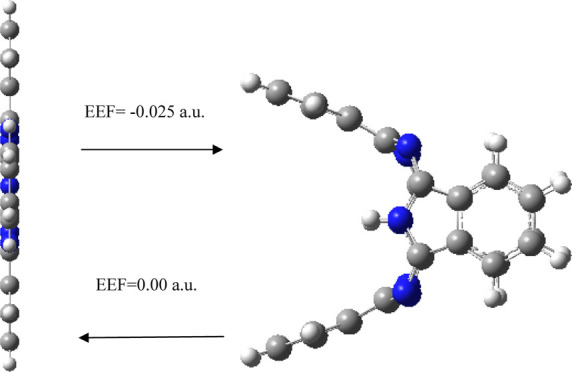
Here, the ground-state structures, electronic structures, polarizability, and spectral properties of metal-free phthalocyanine (H2Pc) under different external electric fields (EEFs) are investigated. The results show that EEF has an ultrastrong regulation effect on various aspects of H2Pc; the geometric structures, electronic properties, polarizability, and spectral properties are strongly sensitive to the EEF. In particular, an EEF of 0.025 a.u. is an important control point: an EEF of 0.025 a.u. will bend the benzene ring subunits to the positive and negative x directions of the planar molecule. Flipping the EEF from positive (0.025 a.u.) to negative (−0.025 a.u.) flips also the bending direction of benzene ring subunits. The H2Pc shows different dipole moments projecting an opposite direction along the x direction (−84 and 84 Debye for EEFs of −0.025 and 0.025 a.u., respectively) under negative and positive EEF, revealing a significant dipole moment transformation. Furthermore, when the EEF is removed, the molecule can be restored to the planar structure. The transformation of the H2Pc structure can be induced by the EEF, which has potential applications in the molecular devices such as molecular switches or molecular forceps. EEF lowers total energy and reduces highest occupied molecular orbital–lowest unoccupied molecular orbital (HOMO–LUMO) gap; especially, an EEF of 0.025 a.u. can reduce the HOMO–LUMO gap from 2.1 eV (in the absence of EEF) to 0.37 eV, and thus, it can enhance the molecular conductivity. The first hyperpolarizability of H2Pc is 0 in the absence of EEF; remarkably, an EEF of 0.025 a.u. can enhance the first hyperpolarizability up to 15,578 a.u. Therefore, H2Pc under the EEF could be introduced as a promising innovative nonlinear optical (NLO) nanomaterial such as NLO switches. The strong EEF (0.025 a.u.) causes a large number of new absorption peaks in IR and Raman spectra and causes the redshift of electronic absorption spectra. The changes of EEF can be used to regulate the structure transformation and properties of H2Pc, which can promote the application of H2Pc in nanometer fields such as molecular devices.
1. Introduction
Complexes containing carbon rings have a wide range of applications in the nanodevices. Conjugated molecules can be applied to organic field-effect transistors,1 such as Nakayama2 synthesizes different structures of triple azulene oligomers, which exhibits n-type field-effect properties or bipolar field-effect properties. Carbon nanomaterials such as carbon-richrotaxanes and hydrocarbon can be applied to nanodevices such as molecular mechanical locks,3 for example, Pérez designed nanomechanical locks by covering carbon nanotubes with organic rings.4 Phthalocyanines (Pcs) are synthetic analogues of naturally occurring porphyrins and are more accessible as completely synthetic species by virtue of their low cost and straightforward preparation on a large scale.5 The basic Pc macrocycle is a rigid structure consisting of four isoindole subunits attached via meso-positioned nitrogen atoms. There are two hydrogen atoms at the center of metal-free phthalocyanine (H2Pc), which can be replaced by metal and metalloid cations. Phthalocyanine allows diverse functionalities by variation of the central ion, and many divalent metal cations can be accommodated in the center of the Pc macrocycle forming a planar tetracoordinate complex with D4h symmetry, which does not cause a significant distortion of the macrocycle. Metal phthalocyanines (MPcs) (FePc, CoPc, NiPc, CuPc, and ZnPc) are representative planar structure with D4h symmetry and have been most widely studied as electrocatalysts.6 MPcs have been exploited for widespread applications in catalysis,7 fluorescent probes and photosensitisers,8 optoelectronic and redox-active materials,9 sensors,10 nonlinear optics,11 organic field-effect transistors,12 and molecular electronics.13Pc-based materials offer several advantages such as the structure of the active catalytic site in Pcs can be precisely identified, the high performance and selectivity, and the molecular structure of Pcs is highly tailorable, which make them promising candidates for electrocatalytic processes.5
The electronic structure of molecules or clusters will be greatly changed under the action of external electric field (EEF), and some new properties or phenomena are expected to be produced. EEF can catalyze and inhibit chemical reactions,14 induce phase transition, promote molecular diffusion in carbon nanotubes,15 promote the formation of fullerene molecular switch,16 control the selectivity of enzymatic-like bond activations,17 induce change in the selectivity of a metal oxide-catalyzed epoxide rearrangement,18 control the catalytic cycle of cytochrome P450cam,19 accelerate the formation of carbon–carbon bonds,20 catalyze the cis-to-trans isomerization of [3]cumulene derivatives in a scanning tunneling microscope,21 and change the interfacial energy band of photomultiplication-type organic photodetectors.22−24 The free-base tetraphenyl-porphyrin molecule has two hydrogen atoms in its inner cavity that can be flipped between two states with different local conductance levels using the electron current through the tip of a scanning tunneling microscope25 and can function as a molecular conductance switch. The encapsulated Gd atom in Gd@C82 can form a charged center that sets up two single-electron transport channels at a gate voltage of ±11 V (corresponding to a coercive field of ∼50 mV Å–1), which can form a gate-controlled switching between two electronic states.26 A scanning tunneling microscope can generate large EEF and offers unique opportunities to operate individual switches on the atomic scale.25,27 Experimentally, trans–cis isomerization of the azobenzene molecule can be induced under the threshold voltages (scanning tunneling microscope tip) between 0.1 and 0.7 V/Å;28 these experimental values are smaller than those calculated for the switching molecule by the EEF (about 1–2 V/Å).29 Therefore, the investigation of the EEF effect of metal-free phthalocyanine (H2Pc) would be quite beneficial to expand the application of H2Pc.
2. Computational Methods
Geometry optimizations and frequency analyses were conducted, and electronic structures were studied at the B3LYP/6-311+G(d,p) level. The B3LYP/6-311+G(d,p) is a reliable level for H2Pc; specifically, theoretical calculation results of the bond length of carbon–nitrogen with the B3LYP/6-311+G(d,p) level agree with the experimental bond length.30,31 Therefore, the discussion below is on the basis of B3LYP/6-311+G(d,p) level. In this paper, atomic unit is employed to represent the magnitude of EEF, 1 a.u. = 51.42 V/Å. Electronic absorption spectra were investigated by means of the time-dependent DFT (TD-DFT) method with B3LYP/6-311+G(d,p) level at optimized ground-state geometries. All computations were performed using Gaussian 16 software;32 molecular structure maps were plotted by GaussView 6. The EEF was applied via “field” keyword in Gaussian program. Note that the sign convention of EEF employed in Gaussian is opposite to the general physical definition.27 In the whole article, we follow common physical convention of the EEF direction. All analyses and various types of isosurface map drawings were realized using the Multiwfn 3.7(dev) code.33
3. Results and Discussion
3.1. Structure of H2Pc
The ground-state structure of the H2Pc molecule is shown in Figure 1. Figure 1a is the structural diagram observed along the x-direction (the positive x-direction is perpendicular to the page toward the interior), and the origin of the coordinate is the molecular center. Figure 1b is the structural diagram observed along the z direction (the positive z direction is perpendicular to the page toward the exterior). The H2Pc molecule has a square planar structure (D2h symmetry), and four isoindole subunits are symmetrically distributed in the z and y directions, respectively, connected by N atoms. Each isoindole subunit has a benzene ring subunit (the part surrounded by the red dotted line in Figure 1a, containing six C atoms and four hydrogen atoms), and the two central hydrogen atoms are located on the z axis and are connected to the N atom. The molecular length in the z or y direction is equal to 1.5 nm. The dipole moment of the H2Pc molecule is 0 (the dipole moments in the x, y, and z directions are all 0); this is because the molecule has the high symmetry and the distribution of positive and negative charges also has high symmetry. It can be seen from the calculation results that H2Pc possesses 21 delocalized π bonds, which quite surprisingly follow the 4m + 2 Hückel rule for aromaticity, and both the highest occupied molecular orbital (HOMO) and lowest unoccupied molecular orbital (LUMO) are π orbitals.
Figure 1.
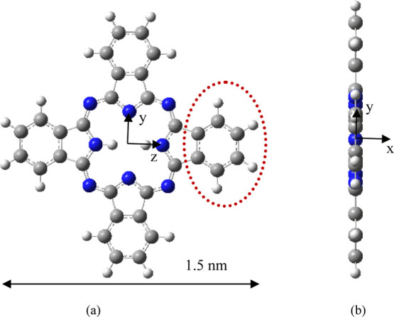
Structure of H2Pc. (a) Structure observed along the x direction and (b) structure observed along the z direction.
3.2. Structure Transformation of H2Pc under the EEF
Different EEFs (−0.025 to 0.025 a.u., negative sign indicates that the EEF direction is the negative x direction) are applied along the x-axis of the molecule to investigate its molecular structure and properties. All structures optimized under different magnitudes of EEF do not have any imaginary frequency, and the lowest harmonic frequencies of all structures are listed in Table 1. When the electric field is applied along the negative x direction, with the increase of the electric field strength (0–0.01 a.u.), the four benzene ring subunits of the molecule are almost bent to the left (negative x direction, as shown in Figure 2a–c), and the bending amplitude is small. With the further increase of the value of the electric field (0.015 a.u.), the molecule is no longer bent to the left as a whole, and a slight change occurs. The two benzene ring subunits in the y direction are further bent to the left, although two benzene ring subunits in the z direction (the axis where the two hydrogen atoms are located) are also bent further to the left, but the length of the left bend is shorter than that of the benzene ring subunits in the y direction (Figure 2d). With the further increase of the value of the electric field (0.020 a.u.), the molecule is also no longer bent to the left (negative x direction) as a whole, and a large change occurs; the two benzene ring subunits in the y direction are further bent to the left (negative x direction), two benzene ring subunits in the z direction are bent to the left by a small amplitude, and the bending length is shorter than that under an electric field strength of 0.015 a.u., which indicate that there is a reverse recovery trend (Figure 2e). When the value of the EEF increases to 0.025 a.u., the structure changes strangely, the two benzene ring subunits in the y direction are further bent to the left (negative x direction), and the two benzene ring subunits in the z direction are bent to the right (positive x direction); the length of the bend on both sides is about the same (Figure 2f). When an EEF is applied along positive x direction, the change law is just opposite to that when a negative EEF is applied, that is, when the field strength of positive x direction is increased to 0.025 a.u., the two benzene ring subunits in the y direction bend to the right (positive x direction), and the two benzene ring subunits in the z direction bend to the left (negative x direction, Figure 3). The two hydrogen atoms in the center of the molecule have a certain regulating effect on the bending direction. When the electric field of x direction is increased to 0.025 a.u., the bending direction of the benzene ring subunits in the z axis (the axis where the two hydrogen atoms are located) is just opposite to the direction of the EEF. In order to verify the transformation of the molecular structure, the structure under the action of EEF is taken as the initial structure and the structure is optimized without EEF, and the final optimized stable structure was restored to the original planar structure (Figure 4), indicating that the transformation of molecular structure can be regulated by the EEF. The peculiar structural transformation of the H2Pc molecule under the action of an EEF is promising to apply to a molecular switch which is switched between an on and off state because of the different structures. For example, the periodic EEF in the x direction can make the planar structure and three-dimensional structure change periodically to achieve the function of molecular switches. On the other hand, under the action of an EEF, bent benzene ring subunits can form a mechanical arm, which may be used in molecular level forceps.
Table 1. Lowest Frequencies, Energy, HOMO Energy, LUMO Energy, HOMO–LUMO Gap, and Dipole Moments (μ) of H2Pc under Different EEFs.
| EEF/a.u. | lowest frequencies/cm–1 | energy/Hartree | HOMO energy/eV | LUMO energy/eV | HOMO–LUMO gap/eV | μ/Debye |
|---|---|---|---|---|---|---|
| 0 | 18 | –1668.7302 | –5.31 | –3.19 | 2.12 | 0 |
| 0.005 | 18 | –1668.7334 | –5.31 | –3.20 | 2.11 | 3.18 |
| 0.010 | 16 | –1668.7429 | –5.33 | –3.23 | 2.10 | 6.50 |
| 0.015 | 11 | –1668.7593 | –5.35 | –3.27 | 2.08 | 10.19 |
| 0.020 | 10 | –1668.7842 | –5.31 | –3.39 | 1.92 | 15.86 |
| 0.025 | 18 | –1668.8706 | –5.99 | –5.62 | 0.37 | 84.21 |
| –0.005 | 18 | –1668.7334 | –5.31 | –3.20 | 2.11 | –3.18 |
| –0.010 | 16 | –1668.7429 | –5.33 | –3.23 | 2.10 | –6.50 |
| –0.015 | 11 | –1668.7593 | –5.35 | –3.27 | 2.08 | –10.19 |
| –0.020 | 10 | –1668.7842 | –5.31 | –3.39 | 1.92 | –15.86 |
| –0.025 | 18 | –1668.8706 | –5.99 | –5.62 | 0.37 | –84.21 |
Figure 2.
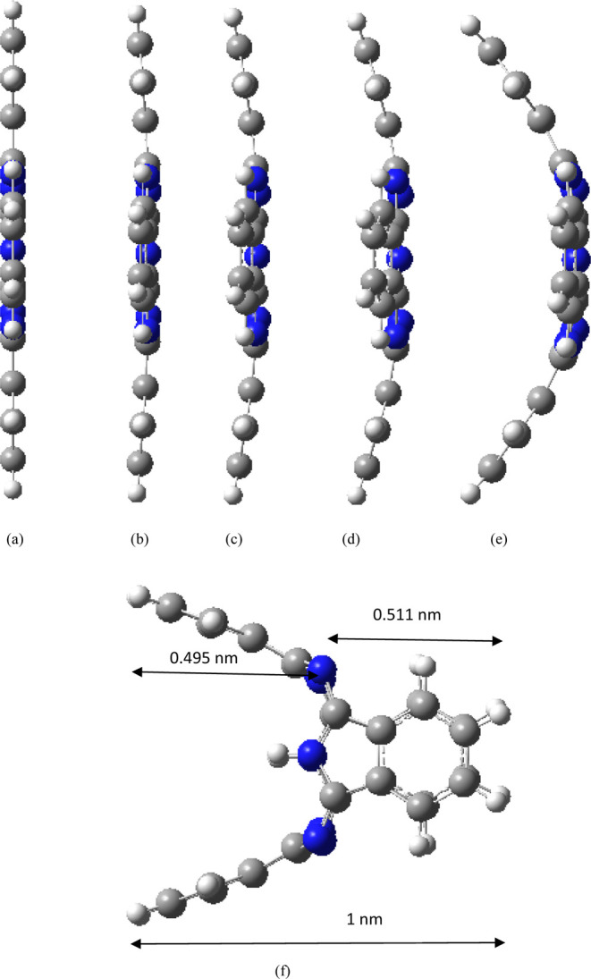
Structures under different EEFs (direction of EEF is negative x direction). (a) 0, (b) −0.005, (c) −0.010, (d) −0.015, (e) −0.020, and (f) −0.025 a.u.
Figure 3.
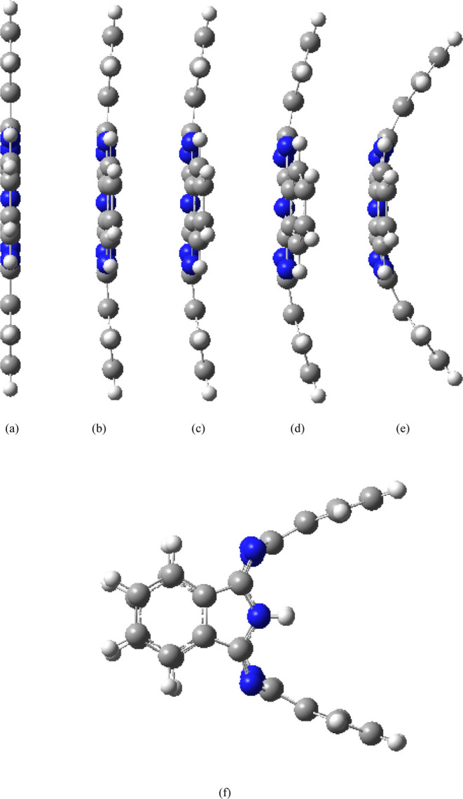
Structures under different EEFs (direction of EEF is positive x direction). (a) 0, (b) 0.005, (c) 0.010, (d) 0.015, (e) 0.020, and (f) 0.025 a.u.
Figure 4.
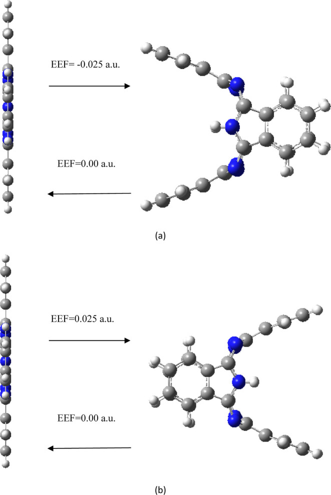
Transformation of the molecular structure in the absence/presence of EEF. (a) Direction of EEF is negative x direction, and (b) direction of EEF is positive x direction.
At an EEF of 0 a.u., the two benzene ring subunits in the y direction have some positive charges, and the two benzene ring subunits in the z direction (the axis where the two hydrogen atoms are located) have some positive charges (total charge of benzene ring subunits in the z direction is less than that of benzene ring subunits in the y direction, where the two hydrogen atoms in the center of the molecule regulate the charge distribution). From f = qE, when the EEF in the negative x direction is applied, four benzene ring subunits will receive a force f in the negative x direction, so the four benzene ring subunits are bent to the left (negative x direction), and similarly, if the EEF in the positive x direction is added, the four benzene ring subunits are bent to the right (positive x direction) as a whole. The molecules are bent along the direction of the EEF, the positive and negative charge centers are shifted under the action of the EEF, and the molecules are polarized. Under the action of the EEF, the positive and negative charges move in the positive and negative directions of the EEF, respectively, further stretching the molecule to bend the molecule and increase the polarization electric field; on the other hand, when the polarization electric field and the EEF are balanced, the molecule reaches the equilibrium structure. With the further increase of the value of EEF (0.020 a.u.), because the total positive charge of the two benzene ring subunits in the y direction is greater than the total positive charge of the two benzene ring subunits in the z direction, the force of the two benzene ring subunits in the y direction is larger than that of the two benzene ring subunits in the z direction, so the two benzene ring subunits in the y direction are more bent to the left. However, the two benzene ring subunits in the z direction are only bent a little, the polarized electric field generated by them can balance the applied electric field, and the molecule reaches the equilibrium structure. With the further increase of the value of EEF (0.025 a.u.), since the total positive charge of the two benzene ring subunits in the y direction is greater than that of the two benzene ring subunits in the z direction, the two benzene ring subunits in the y direction are much more stressed than the two benzene ring subunits in the z direction, so the two benzene ring subunits in the y direction first bend to the left, and if the two benzene ring subunits in the z direction are bent to the left, the polarized electric field generated by them cannot balance the applied electric field, and the molecules cannot reach the equilibrium structure. Therefore, the two benzene ring subunits in the z direction will bend to the right, resulting in a larger polarized electric field to balance the applied electric field, and the molecule reaches the equilibrium structure.
With the increase in the value of EEF, the molecular dipole moment μ increases gradually (the dipole moment in the x direction is not 0, and the dipole moment in the y and z directions is still 0), and with the increase of the EEF, the dipole moment μ increases nonlinearly. Because the dipole moment μ = Rq, where the direction is from the center of the negative charge to the center of the positive charge, q is the amount of charge, and R is the distance between the positive and negative charges. For example, with the gradual increase of the value of EEF (negative x direction), the negative charge on the positive side of the x axis increases, the positive charge on the negative side of the x axis increases, and the length of the molecule bending in the x direction also increases (resulting in an increase of R), which will lead to an increase of dipole moment. As shown in Table 1, H2Pc shows different dipole moments projecting an opposite direction along the x direction (−84 and 84 Debye for a negative and positive EEF of 0.025 a.u., respectively) under a negative and positive EEF of 0.025 a.u., revealing a significant dipole moment transformation. Thus, EEF > 0 increases the value of μ from 0 Debye (at EEF = 0) to 84 Debye, whereas EEF < 0 flips the direction of μ and increases its value of μ from 0 Debye (at EEF = 0) to 84 Debye. The EEF augmentation of the dipoles with regard to EEF = 0 reflects augmented ionicity of the molecule along the x axis. The results have demonstrated that an EEF could act on symmetry molecules, thus changing the conformation, and the EEF can regulate the size and direction of the dipole moment, which has potential applications in molecular devices and electrocatalysis.14
3.3. Electron Structure under the Action of EEF
On the basis of optimizing the ground-state stable structure of H2Pc under different EEFs, the molecular energy levels of H2Pc under different EEFs were analyzed. Table 1 shows the LUMO energy EL, HOMO energy EH, and the LUMO–HOMO energy gap Eg (Eg = EL – EH). The LUMO level is numerically comparable to the electron affinity, and the lower the EL, the more readily the molecule accepts electrons. The HOMO level reflects the strength of the molecule’s ability to lose electrons. The higher the EH, the easier the molecule loses electrons. The size of Eg reflects the ability of electrons to transition from occupied orbitals to empty orbits. The smaller the Eg, the greater the chemical activity. As can be seen from Table 1, Eg is 2.1 eV in the absence of EEF. In the presence of an EEF of 0–0.020 a.u., EL and EH have not changed much; however, at an EEF of 0.025 a.u., EL and EH have a big decrease. Since Eg = EL – EH, with the increase of the EEF, the variation trend of EL and EH leads to the decrease of Eg all the time. When the field strength varies from 0 to 0.020 a.u., it only decreases slightly with the increase of the EEF. When the field strength is increased to 0.025 a.u., Eg decreases to 0.37 eV. The results show that with the increase of the EEF strength, the electrons occupying the orbital are easily excited to the empty orbital, forming holes, so that H2Pc is easily excited, and it also shows that with the increase of the EEF, the chemical activity of H2Pc is greater. Due to the intrinsic semiconducting nature of the Pc molecule, electron transfer in the electrocatalytic process is restricted, which adversely affects its electrochemical performance.5,34 However, the EEF can reduce the Eg from 2 to 0.37 eV, which is conducive to electron transfer and is expected to be further applied in electrocatalysis.
In order to describe the characteristics of electron delocalization under the action of EEF, the electron localization function (ELF)35 is analyzed. Figure 5 shows the ELF of the valence electron under an EEF (the direction of the EEF is negative x-direction), and the isosurface value is 0.6. As shown in Figure 5, in the absence of EEF, the isosurface map is connected across the entire molecular plane. At an EEF intensity of 0.025 a.u., the isosurface map is connected in the whole molecule, and two mushroom-shaped regions appear on the right side of the molecule, indicating that the electrons are delocalized to the right side of the molecule. Figures S1–S4 show the ELF of the valence electron with the isosurface values of 0.70, 0.80, 0.90, and 0.96, respectively. As can be seen from Figures 5 and S1–S4, the delocalization characteristics in the molecular skeleton do not change much in the absence/presence of EEF. However, under an EEF of 0.025 a.u., two mushroom-shaped regions appear on the right side of the molecule, indicating that the electrons are delocalized to the right side of the molecule and EEF can enhance electron delocalization. It further shows that the EEF is conducive to electron transfer and is expected to be further applied in electrocatalysis. The isosurface map in the presence of positive EEF is exactly the opposite of distribution in the presence of negative EEF. The electron delocalization can be controlled by the EEF, and the delocalization characteristics of different positions of the molecule can also be controlled by the EEF, which has certain guiding significance for the use of H2Pc to make molecular devices. The ground-state properties and electron delocalization properties of H2Pc will change under the action of EEF, which may lead to interesting results.
Figure 5.
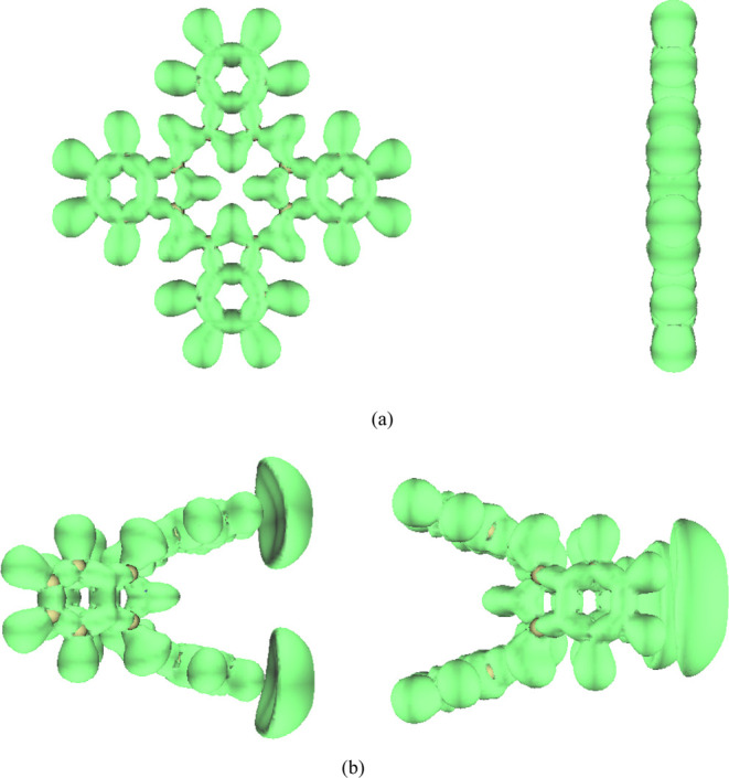
ELF, the isovalue is set to 0.6. (a) EEF is 0 a.u.; the left is observed along the x direction and the right is observed along the z direction and (b) EEF is −0.025 a.u.; the left is observed along the y direction and the right is observed along the z direction.
3.4. Polarization Properties
To understand the polarization properties of H2Pc, the polarizability of H2Pc was calculated, including average isotropic polarizability α, anisotropic polarizability Δα, and the magnitude of first hyperpolarizability β0. Δα describes the response of the system to electric fields from different directions. The larger the value of Δα, the stronger is the anisotropic response to the EEF. The first hyperpolarizability is also called the second-order nonlinear optical (NLO) coefficient, which evaluates the NLO properties of molecules. The polarizability in the presence of positive EEF is the same as that in the presence of negative EEF, and only the negative EEF case is shown in Table 2. It can be seen from Table 2 that with the EEF intensity varying from 0 to 0.020 a.u., the isotropic polarizability of H2Pc is proved to be increasing with the increase of the EEF intensity. When the EEF intensity is increased to 0.025 a.u., the isotropic polarizability increases to 1714 a.u., almost triple of that in the absence of electric field. It can be seen from Table 2 that when the EEF intensity varies from 0 to 0.020 a.u., the anisotropic polarizability of H2Pc is proved to be decreasing with the increase of the EEF intensity. However, when the EEF intensity is increased to 0.025 a.u., the anisotropic polarizability increases to 943 a.u., indicating the change of H2Pc in the action of EEF. It can be seen from Table 2 that the first hyperpolarizability of H2Pc in the absence of EEF is equal to 0, indicating that there is no NLO response. The first hyperpolarizability of H2Pc is proved to be increasing with the increase of the EEF intensity, indicating that H2Pc has strong NLO response. Specially, the EEF intensity of 0.025 a.u. enhances the first hyperpolarizability up to 15,578 a.u. Hence, H2Pc might be considered as a promising NLO nanomaterial and can be applied to NLO molecular devices. The molecule exhibits different structural features in the EEF and has different charge distribution characteristics, resulting in different polarization characteristics. To illustrate the trend of polarizability, molecular van der Waals (vdW) volume (the volume surrounded by a vdW surface and an electron density of 0.001 a.u. isosurface is defined as molecular vdW surface)36 is calculated. As can be seen from Table 2, the variation trend of vdW volume with electric field is consistent with that of polarizability with electric field. Under the action of the EEF, the molecule is bent and the positive and negative charges move in the positive and negative directions of the EEF, respectively, further stretching the molecule to bend the molecule and increase the molecular volume. Since the total number of electrons in the system is unchanged, the larger the vdW volume corresponds to the wider electron density distribution, the more significant the response of the electrons in the system to the EEF is, indicating that the average isotropic polarizability and the magnitude of first hyperpolarizability increase with the increase of the EEF intensity. Anisotropic polarizability reflects the system response to the electric field from different directions; the larger value corresponds to the stronger anisotropy. At the beginning, with the increase of the EEF intensity, the change of the structure leads to the weakening of the anisotropy. At an EEF intensity of 0.025 a.u., due to the abrupt change of the structure, the electronic structure changes greatly, which leads to the increase of the anisotropic polarizability.
Table 2. Polarizabilities of H2Pc under Different EEFs.
| EEF/a.u. | α/a.u. | Δα/a.u. | β0/a.u. | vdW volume/Å3 |
|---|---|---|---|---|
| 0 | 654 | 695 | 0 | 594.56 |
| –0.005 | 655 | 694 | 762 | 594.66 |
| –0.010 | 657 | 691 | 1540 | 595.13 |
| –0.015 | 660 | 682 | 2392 | 595.90 |
| –0.020 | 671 | 636 | 5396 | 597.20 |
| –0.025 | 1714 | 943 | 15578 | 641.97 |
3.5. Infrared and Raman Spectra under the EEF
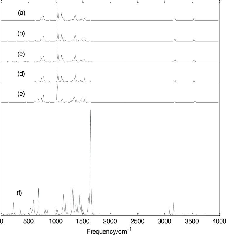
Figure 6 shows the infrared spectra of H2Pc under different EEFs. The infrared spectra in the presence of positive EEF are exactly the same as that in the presence of negative EEF, and only the infrared spectra in the presence of negative EEF are shown in the figure. In the absence of EEF, the minimum harmonic frequency is 18 cm–1 and the maximum harmonic frequency is 3602 cm–1; there are several strong absorption bands in the low-frequency region and two absorption bands in the high-frequency region. The strongest peak is at 1046 cm–1; this vibration mode is the stretching vibration in the molecular plane, and this vibration mode has no Raman activity. It can be seen from Figure 6 that when the EEF is applied, as the EEF intensity varies from 0 to 0.015 a.u., the main band characteristics of the infrared spectrum hardly change. When the EEF intensity increases to 0.020 a.u., the main band characteristics of the infrared spectrum do not change much, but there are two absorption bands with some absorption peaks added, and some vibration modes show infrared activity. When the EEF intensity increases to 0.025 a.u., the infrared spectrum changes greatly, and some enhanced vibrational modes appear, especially the strongest absorption peak moves to the high-frequency direction (1640 cm–1) and two relatively strong absorption bands appear in the high-frequency region. As mentioned above, under the action of an EEF, the molecular structure changes, resulting in the shift of the frequency and the enhancement or weakening of some vibration modes.
Figure 6.
Calculated infrared spectra under different EEFs. (a) 0, (b) −0.005, (c) −0.01, (d) −0.015, (e) −0.02, and (f) −0.025 a.u.
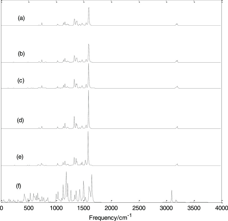
Figure 7 shows the Raman spectra under different EEFs. The Raman spectra in the presence of positive EEF are also exactly the same as that in the presence of negative EEF, and only the Raman spectra in the presence of negative EEF are shown in the figure. In the absence of EEF, the strongest Raman-active mode is at 1592 cm–1, and this vibrational mode has no infrared activity. Similar to the variation law of the infrared spectra, under the EEF, as the electric field intensity varies from 0 to 0.020 a.u., the Raman spectrum does not change much. When the electric field intensity increases to 0.025 a.u., the Raman spectrum changes greatly, and many enhanced vibrational modes appear; a relatively strong absorption band appears in the high-frequency region. The calculation results show that in the absence of EEF, the strongest infrared-active mode has no Raman activity, while the strongest Raman-active vibration mode has no infrared activity. In addition, in the absence of EEF, there are many infrared-inactive vibration modes and Raman-inactive vibration modes. When an EEF is applied, especially at 0.025 a.u., all vibrational modes are IR-active and Raman-active. If molecular vibrations lead to changes in molecular dipole moment, such vibrational modes are infrared-active; if molecular vibrations lead to changes in molecular polarizability, such vibrational modes are Raman-active. As mentioned above, the applied electric field will change the dipole moment and polarizability of the molecule and further changes the infrared and Raman activity of its vibrational modes.
Figure 7.
Calculated Raman spectra under different EEFs. (a) 0, (b) −0.005, (c) −0.01, (d) −0.015, (e) −0.02, and (f) −0.025 a.u.
3.6. Electronic Absorption Spectra under EEF
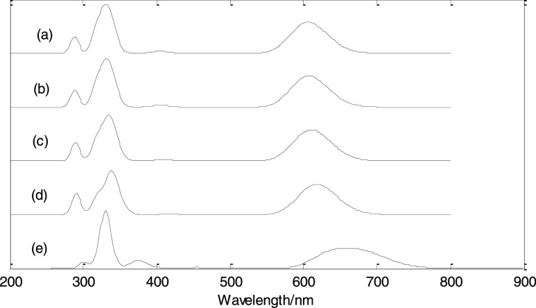
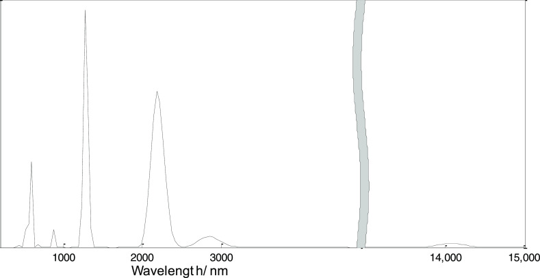
On the basis of the geometry optimization, the TD-B3LYP/6-311+G(d,p) method was used to study the electronic absorption spectra, as shown in Figures 8 and 9. Similar to infrared and Raman spectra, the electronic absorption spectra in the presence of positive EEF are exactly the same as that in the presence of negative EEF, and only the electronic absorption spectra in the presence of negative EEF are shown in the figure. The calculation results show that at an EEF of 0 a.u., the first absorption peak is about at 606 nm, which is formed by the excitations of S0 → 1 (oscillator intensity 0.40) and S0 → 2 (oscillator intensity 0.45). At the EEF intensities of 0.005, 0.010, and 0.015 a.u., the first absorption peaks are about at 607, 608, and 618 nm, respectively, and they are formed by the excitations of S0 → 1 (oscillator intensity 0.40) and S0 → 2 (oscillator intensity 0.45). At an EEF intensity of 0.020 a.u., the first absorption peak is about at 662 nm, which is formed by the excitations of S0 → 1 (oscillator strength 0.38) and S0 → 2 (oscillator strength 0.40); at an EEF intensity of 0.025 a.u., the first absorption peak is at 14,079 nm, which is formed by the excitation of S0 → 1 (oscillator strength 0.0053).
Figure 8.
Electronic absorption spectra under different EEFs. (a) 0, (b) −0.005, (c) −0.01, (d) −0.015, and (e) −0.02 a.u.
Figure 9.
Electronic absorption spectrum under an EEF of −0.025 a.u.
As the EEF intensity varies from 0 to 0.015 a.u., the excitation characteristics are basically unchanged, and only the excitation wavelength has a small redshift. When the value of EEF intensity increases to 0.020 a.u., the excitation characteristics change greatly, the excitation wavelength increases, and there is a large redshift. When the value of EEF intensity increases to 0.025 a.u., the excitation characteristics change dramatically, and the wavelength of the first excited state is red-shifted to 14,079 nm. At the EEF intensities of 0, 0.005, 0.01, 0.015, 0.020, and 0.025 a.u., the corresponding maximum excitation wavelengths (first excited state) are 609, 610, 613, 622, 686, and 14,079 nm, respectively. The size of the LUMO–HOMO energy gap can also reflect the excitation energy (excitation wavelength) of the first excited state. From the previous calculation results, it can be seen that with the increase of the EEF, Eg decreases, and the energy is inversely proportional to the wavelength, which just reflects the increasing excitation wavelength with the increasing EEF.
The excitation characteristics originate from the electron transitions between different orbitals. The EEF changes the electronic structure, resulting in the change of the orbital and the contribution of the orbital transition to the excited state, so the EEF leads to different excitation characteristics. By changing the EEF, on the one hand, the excitation wavelength can be changed; on the other hand, the absorption intensity can be controlled by changing the oscillator intensity of the excited state by the EEF. In addition, the electron absorbs photons and transitions from the ground state to the excited state with nonzero oscillator strength and then from the high excited state to the low excited state and emits light of different wavelengths. However, the EEF will lead to the change of excitation energy and oscillator intensity of the excited state, and the emission wavelength and luminous intensity can be changed by an EEF. In summary, by changing the EEF, the excitation wavelength can be changed, and the oscillator intensity of the excited state can also be changed to control the intensity of the absorption peak and the intensity of the luminescence.
4. Conclusions
This work demonstrated a phenomenon of structure transformation, dipole moment transformation, and the first hyperpolarizability transformation of H2Pc via EEF. The results show that EEF has an ultrastrong regulation effect on various aspects of H2Pc. In particular, an EEF of 0.025 a.u. will bend the benzene ring subunits in the positive and negative x directions of the planar molecule. However, when the EEF is removed, the molecules can be restored to the planar structure. The transformation of the H2Pc structure can be induced by the EEF, which has potential applications in the molecule switches. EEF can reduce HOMO–LUMO gap, and especially an EEF of 0.025 a.u. can reduce the energy gap to 0.37 eV and enhance the molecular conductivity. The first hyperpolarizability of H2Pc is 0 in the absence of EEF. Remarkably, an electric field of 0.025 a.u. enhances the first hyperpolarizability up to 15,578 a.u. Therefore, H2Pc under the EEF could be introduced as a promising innovative NLO nanomaterial. The strong EEF can regulate IR, Raman spectra, and electronic absorption spectra. The changes of EEF can be used to control the structure transformation and properties of H2Pc, which can provide new insights into constructing future practical single-molecule devices.
Acknowledgments
This work was supported by the National Natural Science Foundation of China (11804065), the Central Guiding Local Science and Technology Development Foundation of China (grant no. QK ZYD[2019]4012), and the Growth Foundation for Young Scientists of Education Department of Guizhou Province, China (grant no: QJH KY[2022]310).
Supporting Information Available
The Supporting Information is available free of charge at https://pubs.acs.org/doi/10.1021/acsomega.2c04941.
ELF of H2Pc in the absence/presence of EEF (PDF)
The authors declare no competing financial interest.
Supplementary Material
References
- Zhou W.; Yutronkie N. J.; Lessard B. H.; Brusso J. L. From chemical curiosity to versatile building blocks: unmasking the hidden potential of main-group phthalocyanines in organic field-effect transistors. Mater. Adv. 2021, 2, 165–185. 10.1039/d0ma00864h. [DOI] [Google Scholar]
- Yamaguchi Y.; Takubo M.; Ogawa K.; Nakayama K.; Koganezawa T.; Katagiri H. Terazulene Isomers: Polarity Change of OFETs through Molecular Orbital Distribution Contrast. J. Am. Chem. Soc. 2016, 138, 11335–11343. 10.1021/jacs.6b06877. [DOI] [PubMed] [Google Scholar]
- Sluysmans D.; Stoddart J. F. The Burgeoning of Mechanically Interlocked Molecules in Chemistry. Trends Chem. 2019, 1, 185–197. 10.1016/j.trechm.2019.02.013. [DOI] [Google Scholar]
- Pérez E. M. Putting Rings around Carbon Nanotubes. Chemistry 2017, 23, 12681–12689. 10.1002/chem.201702992. [DOI] [PubMed] [Google Scholar]
- Yang S.; Yu Y.; Gao X.; Zhang Z.; Wang F. Recent advances in electrocatalysis with phthalocyanines. Chem. Soc. Rev. 2021, 50, 12985–13011. 10.1039/d0cs01605e. [DOI] [PubMed] [Google Scholar]
- Zagal J. H.; Griveau S.; Silva J. F.; Nyokong T.; Bedioui F. Metallophthalocyanine-based molecular materials as catalysts for electrochemical reactions. Coord. Chem. Rev. 2010, 254, 2755–2791. 10.1016/j.ccr.2010.05.001. [DOI] [Google Scholar]
- Sorokin A. B. Phthalocyanine metal complexes in catalysis. Chem. Rev. 2013, 113, 8152–8191. 10.1021/cr4000072. [DOI] [PubMed] [Google Scholar]
- Li X.; Zheng B.-D.; Peng X.-H.; Li S.-Z.; Ying J.-W.; Zhao Y.; Huang J.-D.; Yoon J. Phthalocyanines as medicinal photosensitizers: Developments in the last five years. Coord. Chem. Rev. 2019, 379, 147–160. 10.1016/j.ccr.2017.08.003. [DOI] [Google Scholar]
- Wong E. W.; Walsby C. J.; Storr T.; Leznoff D. B. Phthalocyanine as a chemically inert, redox-active ligand: structural and electronic properties of a Nb(IV)-oxo complex incorporating a highly reduced phthalocyanine(4-) anion. Inorg. Chem. 2010, 49, 3343–3350. 10.1021/ic902409n. [DOI] [PubMed] [Google Scholar]
- Bouvet M.; Gaudillat P.; Suisse J.-M. Phthalocyanine-based hybrid materials for chemosensing. J. Porphyr. Phthalocyanines 2013, 17, 913–919. 10.1142/s1088424613300073. [DOI] [Google Scholar]
- de la Torre G.; Vázquez P.; Agulló-López F.; Torres T. Role of structural factors in the nonlinear optical properties of phthalocyanines and related compounds. Chem. Rev. 2004, 104, 3723–3750. 10.1021/cr030206t. [DOI] [PubMed] [Google Scholar]
- Melville O. A.; Grant T. M.; Lochhead K.; King B.; Ambrose R.; Rice N. A.; Boileau N. T.; Peltekoff A. J.; Tousignant M.; Hill I. G.; Lessard B. H. Contact Engineering Using Manganese, Chromium, and Bathocuproine in Group 14 Phthalocyanine Organic Thin-Film Transistors. ACS Appl. Electron. Mater. 2020, 2, 1313–1322. 10.1021/acsaelm.0c00104. [DOI] [Google Scholar]
- Claessens C. G.; Hahn U.; Torres T. Phthalocyanines: from outstanding electronic properties to emerging applications. Chem. Rec. 2008, 8, 75–97. 10.1002/tcr.20139. [DOI] [PubMed] [Google Scholar]
- Shaik S.; Mandal D.; Ramanan R. Oriented electric fields as future smart reagents in chemistry. Nat. Chem. 2016, 8, 1091–1098. 10.1038/nchem.2651. [DOI] [PubMed] [Google Scholar]
- English N. J.; Waldron C. J. Perspectives on external electric fields in molecular simulation: progress, prospects and challenges. Phys. Chem. Chem. Phys. 2015, 17, 12407–12440. 10.1039/c5cp00629e. [DOI] [PubMed] [Google Scholar]
- Foroutan-Nejad C.; Andrushchenko V.; Straka M. Dipolar molecules inside C70: an electric field-driven room-temperature single-molecule switch. Phys. Chem. Chem. Phys. 2016, 18, 32673–32677. 10.1039/c6cp06986j. [DOI] [PubMed] [Google Scholar]
- Shaik S.; de Visser S. P.; Kumar D. External electric field will control the selectivity of enzymatic-like bond activations. J. Am. Chem. Soc. 2004, 126, 11746–11749. 10.1021/ja047432k. [DOI] [PubMed] [Google Scholar]
- Gorin C. F.; Beh E. S.; Kanan M. W. An electric field-induced change in the selectivity of a metal oxide-catalyzed epoxide rearrangement. J. Am. Chem. Soc. 2012, 134, 186–189. 10.1021/ja210365j. [DOI] [PubMed] [Google Scholar]
- Lai W.; Chen H.; Cho K.-B.; Shaik S. External Electric Field Can Control the Catalytic Cycle of Cytochrome P450cam: A QM/MM Study. J. Phys. Chem. Lett. 2010, 1, 2082–2087. 10.1021/jz100695n. [DOI] [Google Scholar]
- Aragonès A. C.; Haworth N. L.; Darwish N.; Ciampi S.; Bloomfield N. J.; Wallace G. G.; Diez-Perez I.; Coote M. L. Electrostatic catalysis of a Diels-Alder reaction. Nature 2016, 531, 88–91. 10.1038/nature16989. [DOI] [PubMed] [Google Scholar]
- Zang Y.; Zou Q.; Fu T.; Ng F.; Fowler B.; Yang J.; Li H.; Steigerwald M. L.; Nuckolls C.; Venkataraman L. Directing isomerization reactions of cumulenes with electric fields. Nat. Commun. 2019, 10, 4482. 10.1038/s41467-019-12487-w. [DOI] [PMC free article] [PubMed] [Google Scholar]
- Zhao Z.; Liu B.; Xie C.; Ma Y.; Wang J.; Liu M.; Yang K.; Xu Y.; Zhang J.; Li W.; Shen L.; Zhang F. Highly sensitive, sub-microsecond polymer photodetectors for blood oxygen saturation testing. Sci. China Chem. 2021, 64, 1302–1309. 10.1007/s11426-021-1008-9. [DOI] [Google Scholar]
- Liu M.; Fan Q.; Yang K.; Zhao Z.; Zhao X.; Zhou Z.; Zhang J.; Lin F.; Jen A. K. Y.; Zhang F. Broadband photomultiplication-type polymer photodetectors and its application in light-controlled circuit. Sci. China Chem. 2022, 65, 1642–1649. 10.1007/s11426-022-1296-2. [DOI] [Google Scholar]
- Zhao Z.; Xu C.; Ma Y.; Yang K.; Liu M.; Zhu X.; Zhou Z.; Shen L.; Yuan G.; Zhang F. Ultraviolet Narrowband Photomultiplication Type Organic Photodetectors with Fabry–Pérot Resonator Architecture. Adv. Funct. Mater. 2022, 32, 2203606. 10.1002/adfm.202203606. [DOI] [Google Scholar]
- Auwärter W.; Seufert K.; Bischoff F.; Ecija D.; Vijayaraghavan S.; Joshi S.; Klappenberger F.; Samudrala N.; Barth J. V. A surface-anchored molecular four-level conductance switch based on single proton transfer. Nat. Nanotechnol. 2011, 7, 41–46. 10.1038/nnano.2011.211. [DOI] [PubMed] [Google Scholar]
- Zhang K.; Wang C.; Zhang M.; Bai Z.; Xie F. F.; Tan Y. Z.; Guo Y.; Hu K. J.; Cao L.; Zhang S.; Tu X.; Pan D.; Kang L.; Chen J.; Wu P.; Wang X.; Wang J.; Liu J.; Song Y.; Wang G.; Song F.; Ji W.; Xie S. Y.; Shi S. F.; Reed M. A.; Wang B. A Gd@C82 single-molecule electret. Nat. Nanotechnol. 2020, 15, 1019–1024. 10.1038/s41565-020-00778-z. [DOI] [PubMed] [Google Scholar]
- Shaik S.; Ramanan R.; Danovich D.; Mandal D. Structure and reactivity/selectivity control by oriented-external electric fields. Chem. Soc. Rev. 2018, 47, 5125–5145. 10.1039/c8cs00354h. [DOI] [PubMed] [Google Scholar]
- Alemani M.; Peters M. V.; Hecht S.; Rieder K. H.; Moresco F.; Grill L. Electric field-induced isomerization of azobenzene by STM. J. Am. Chem. Soc. 2006, 128, 14446–14447. 10.1021/ja065449s. [DOI] [PubMed] [Google Scholar]
- Füchsel G.; Klamroth T.; Dokić J.; Saalfrank P. On the electronic structure of neutral and ionic azobenzenes and their possible role as surface mounted molecular switches. J. Phys. Chem. B 2006, 110, 16337–16345. 10.1021/jp060969v. [DOI] [PubMed] [Google Scholar]
- Hoskins B. F.; Mason S. A.; White J. C. B. The location of the inner hydrogen atoms of phthalocyanine: a neutron diffraction study. J. Chem. Soc. D 1969, 554b–555b. 10.1039/c2969000554b. [DOI] [Google Scholar]
- Yase K.; Yasuoka N.; Kobayashi T.; Uyeda N. Structure of metal-free phthalocyanine stabilized by the addition of its 4-chloro derivative. Acta Crystallogr., Sect. C: Cryst. Struct. Commun. 1988, 44, 514–516. 10.1107/s0108270187011120. [DOI] [Google Scholar]
- Frisch M. J.; Trucks G. W.; Schlegel H. B.; et al. Gaussian 16; Gaussian Inc.: Wallingford CT, 2016.
- Lu T.; Chen F. Multiwfn: A multifunctional wavefunction analyzer. J. Comput. Chem. 2012, 33, 580–592. 10.1002/jcc.22885. [DOI] [PubMed] [Google Scholar]
- Eley D. D. Phthalocyanines as semiconductors. Nature 1948, 162, 819. 10.1038/162819a0. [DOI] [PubMed] [Google Scholar]
- Becke A. D.; Edgecombe K. E. A simple measure of electron localization in atomic and molecular systems. J. Chem. Phys. 1990, 92, 5397–5403. 10.1063/1.458517. [DOI] [Google Scholar]
- Bader R. F. W.; Carroll M. T.; Cheeseman J. R.; Chang C. Properties of atoms in molecules: atomic volumes. J. Am. Chem. Soc. 1987, 109, 7968–7979. 10.1021/ja00260a006. [DOI] [Google Scholar]
Associated Data
This section collects any data citations, data availability statements, or supplementary materials included in this article.


