

Abstract

This paper presents the novelty on a nonlinear proportional integral derivative (NPID) controller developed from the gain values obtained using the Lyapunov-based nonlinear model predictive controller (LyNMPC). The tuning parameters of the proposed controller are taken from the dynamics of the nonlinear system, and these parmeters are dynamic with their value varying according to the error in the system. In this article, the authors have considered two highly nonlinear systems, namely, batch polymerization reactor and quadrotor unmanned aerial vehicle systems. The nonlinear mathematical modeling of the batch reactor as well as the quadrotor system considered from the past literature of authors. The acrylamide polymerization reaction under consideration is an exothermic reaction, thereby making the temperature profile tracking and control a challenging task. The primary aim of this article is to develop the NPID controller based on the LyNMPC algorithm and to validate the NPID on a batch reactor bench-scale plant and on an hardware-in-the-loop platform for the quadrotor hardware. A comparative study of trajectory tracking and control capabilities of LyNMPC on derived non-linear models of the batch reactor and quadrotor system is presented. The system mathematical models are obtained with the help of the first-principle energy balance equation for the batch reactor and with the nonlinear dynamics of the quadrotor which is derived based on Newton–Euler formulations. With LyNMPC, the stability of the nonlinear systems can be improved because the error sensitivity is considered in the cost function.
Introduction
The batch reactors are highly nonlinear and non-steady systems with the primary objective to maintain the reactor temperature with respect to the temperature profile. If the reactor temperature is not maintained with respect to optimal trajectory formed, the reactor may face thermal runaway issues,1−5 which in-turn is due to the sudden conversion of a polymer into a monomer. Hence the optimal control of coolant flow-rate should be used as a manipulated variable with constant heater supply in this experimental study. The highly nonlinear batch reactor stability needs to be ensured while tracking the trajectory to avoid the byproduct formation and thermal runaway. Similarly, unmanned aerial vehicles (UAVs) or drones have been under a rapidly growing field of research. The applications of UAVs have been growing day-by-day and can be categorized as scientific, commercial, or military applications. Micro-UAVs or micro aerial vehicles (MAVs) are classified as miniature UAVs of different build configurations, which vary from the tiny insect sized aircrafts to the small quadrotors and the fixed wing aircrafts. The MAVs due to their smaller size range are more useful in the remote missions, show similarities with their UAV counterparts in various characteristics but differ in terms of the magnitude of the aerodynamic forces experienced, and are more susceptible to external forces due to their smaller size and lower inertia. Hence, the problem of tracking and control of the MAVs is a much more challenging task to achieve.
Model predictive control (MPC) is a sophisticated control method which has various applications in the chemical and petroleum industries, where the physical hard constraints can be handled effectively. The MPC is a finite-boundary iterative optimization technique very useful in situ technique where the plant requirements vary with time. The MPC algorithm determines the control variables from the values obtained previously. Linear MPCs are the most common form of control used in the applications of MPC with the feedback mechanisms due to the mismatch in the model and the process to be controlled. However, there are several instances, where the linear MPCs can be inaccurate, leading the way to modifying the algorithms to control the system in the non-linear scheme. The NMPC, which uses the direct optimal control, is an MPC that uses the nonlinear system model for the predictive function. Similar to MPC, the NMPC also uses the finite boundary conditions for the iterative process, but handles the hard constraints efficiently.
Background Study
The theory of optimal control has been developing since the 1700s. Today the process industries of the world have begun the use of the optimal control strategies such as MPC and its derivatives for the control and optimization of the process performance. In ref (2), the authors have described the modeling of the batch polymerization reactor along with the reaction dynamics-based Wiener neural network (WNN). The authors have modeled the batch reactor using the recorded open-loop input–output data set with the help of the WNN algorithm and designed a linear generalized predictive controller (GPC) for the experimental validation. The input feed along with the initiator is charged all together at a time into the reactor to initiate the reaction, and the reactor temperature needs to be maintained in line with the optimal temperature profile. The objective in this part is to train the neural network to efficiently track the nonlinear temperature profile that is generated optimally by considering the batch reaction time. The second part is designing a GPC using the data obtained from modeling the reactor to successfully track any arbitrary temperature profile. Therefore, this work presents the experimental modeling of a batch reactor and validation of a WNN-based GPC for temperature profile tracking. In ref (1), the authors have presented an efficient nonlinear model based control for the trajectory tracking of the batch reactor and also compared the performance characteristic of the control system with that of a nonlinear model predictive control algorithm. The experiments have been conducted in real-time for a batch acrylamide polymerization reaction. In ref (3), the authors have defined nonlinear ARX- and NARX-based models which have been derived based on the open-loop real-time data from the batch reactor. The authors have compared the performance of conventional linear controllers with that of the proposed controllers. The shortcomings of the conventional controller (PID-based) have been claimed to be addressed with the proposed controllers. In ref (5), the authors have presented a study on a proposed PI controller tuning method using extended predictive control (EPC). The PI controller parameters are claimed to be calculated using an EPC-based controller output and its closed-loop response. The proposed tuning process can be applied to single-input-single-output and multi-input-multi-output stable processes. In ref (4), the authors have addressed the energy consumption problem of a distillation process through an actuator. This has been achieved using an EPC-PI control algorithm. The authors have presented experimental validation of EPC-PI control algorithm and analysis of distillate purity of a lab-scale distillation column. The PI control scheme uses closed-loop data of extended predictive controller (EPC) that has been performed through off-line simulation. The performance of the control method is compared with different schemes such as Hagglund’s one-third rule and Skogestad’s overshoot method. It is noted that the controllers have been implemented for a linear model of the batch distillation column.4,5 Due to its own advantages in handling the soft and hard constraints, the use of predictive control and other optimal control strategies have been used in the aerospace industry/batch reactor for trajectory tracking problems. This trend is evident by the increase in the literature available in the use of optimal control in autopilot design for multirotor aircrafts, especially, quadrotor systems.6−16 The use of a quadrotor system for real-time experiments with nonlinear model predictive7−14 and simulations6,15,16 for the trajectory tracking problem of the quadrotor system have been presented.
The nonlinear model predictive control strategy involves the use of an optimization algorithms such as particle swarm optimization,6 quadratic programming-based optimization,7−9,12,14−16 improved continuation/generalized minimal residual (iC/GMRES) algorithm,10 neural networking-based optimization,11 reinforcement learning based optimization,12 Laguerre function-based optimization,15 and so forth. The optimization algorithm in each case is used to minimize the cost function of the predictive algorithm to generate the optimal control input. Cost function of the optimal control problem of the quadrotor system is derived based on the error in the system, which is dependent on the reference trajectory and the actual system output, and the control action on the system. NMPC algorithms are well known for their constraint handling capabilities. This is crucial in the case of the quadrotor trajectory tracking problem. Literature provides different types of predictive control algorithms of both linear6,9,11,14−16 and non-linear7,8,10,12,13 nature.
The quadrotor dynamic model in the literature is of two types: Newton–Euler formalism-based6−15 and Newton–Quaternion-based formalism.16 The Newton–Euler formalism involves the use of Newtonian physics in the derivation of the translational subsystem and Eulerian formulations for the rotational subsystem. On the other hand, the Newton–Quaternion formalism involves the use of Newtonian physics, similar to the previous case, but the rotational subsystem is derived based on Quaternion formulation for the rotational dynamics of the system.
In refs (17)–19, the authors have presented a design and analysis of different nonlinear robust control techniques, including the scheme of SMC, for a quadrotor UAV. In ref (19), the authors have addressed the control problem based on the nonlinear robust adaptive hierarchical SMC for a quadrotor governed by the thrust constraints and influenced by the inertial parametric uncertainties to gain significant trajectory tracking capabilities. In ref (20), the authors have presented a nonlinear ASMC based on back stepping control strategy for a quadrotor UAV attitude control. The adaptive technique used may not necessitate the upper limits of the parametric uncertainty. In ref (21), the authors have addressed the problem of attitude control in the quadrotor UAV with the internal and the external disturbances by implementing a fuzzy logic-based gain-scheduling (AFGS)-SMC.
In ref (22), the authors have addressed the use of a scheme of MPC to map the trajectory and control of a quadrotor-based UAV. In ref (23), the author has proposed a robust nonlinear MPC strategy for the trajectory control and tracking of a quadrotor, where the attitude and the position are controlled by an SMC algorithm. In ref (18), the authors have addressed the use of a model predictive control technique to solve the quadrotor trajectory detection and the control issue. In ref (24), the authors have presented a brief overview of a few types of techniques of obstacle avoidance for the unmanned aerial vehicles with the higher priority for avoiding the proximal obstacle. In ref (25), the authors have presented a model predictive control algorithm that uses the fewer variables for prediction requiring the lower computational capacity to control a micro aerial vehicle (MAV). In ref (21), the authors have addressed the trajectory monitoring problem for quadrotors in real-time scenarios and is solved using the robust sliding mode observer based on an explicit NMPC (ENMPC) scheme. The control algorithm was derived based on the mathematical model derived from Newton–Euler formulations. In ref (26), authors derived the mathematical model for the UAV using Lagrangian and Eulerian formulation. In ref (27), the authors have introduced a hybrid MPC strategy in combination with a scheme of fuzzy logic. In ref (28), the authors have addressed the problem in controlling the attitude of MAVs, exposed to unknown atmospheric disturbances, with the help of a Lyapunov-based non-linear tracking and control method. In ref (29), the authors have addressed the problem of controlling the states of a micro aerial vehicle by developing a neuro-adaptive controller and fine-tuned using multi-agent optimization techniques. In ref (30), to deal with the aircraft’s nonlinear behavior, the author explained the construction of a nonlinear control system for a quadrotor micro-UAV based on a division into a loop in loop structure and feedback linearization.
In ref (31), the authors have described the derivation and study of a mode switching control strategy for a VTOL UAV with hovering and level flight capability of a micro UAV structure. In ref (32), the authors have presented an adaptive control technique that has been developed for the stability and trajectory control of a quadrotor UAV subjected to parametric deviations. In ref (20), the authors have implemented a novel approach for the position and the attitude tracking control of a quadrotor UAV exposed to parametric and external perturbations.
Case Study 1: Experimental Validation of LyNMPC and Proposed NPID
Batch reactor is widely used in production of polymers, catalysts, in treatment of sewage and oil refineries, where work volume is less or demand for variety is high. It is an example for the closed loop system, where the total volume of reactants remains constant throughout the process. The energy required by the reactants is supplied through a heating element and a stirrer makes sure of uniform spread of heat. The cooling station that circulates coolant to the reactor through jacket/cooling coil helps in removing the excess heat. The temperature is maintained as per the desired profile by manipulating the flow rate of the coolant. Failing to track the desired temperature leads to undesirable products or thermal runaways due to the exothermic nature of batch reactions. The system dynamics of a batch reactor, involves the kinematics of the reaction of interest, reactor, and jacket temperature dynamics. The acrylamide polymerization reaction under consideration is an exothermic reaction thereby making the temperature profile tracking and control a challenging task.
Figure 1 shows the bench-scale batch reactor based on which the dynamic model has been derived, and Figure 2 is a schematic diagram of the batch reactor showing the components involved. The reaction considered in this case study is acrylamide polymerization, which uses ammonium per-sulfate as an initiator [I] and acrylamide as monomer [M] which are represented by the equations1 below
| 1 |
| 2 |
The reactor temperature Tr and jacket temperature Tj dynamics are given by the equations below
| 3 |
| 4 |
where
| 5 |
| 6 |
| 7 |
| 8 |
| 9 |
Figure 1.

Bench-scale batch reactor setup available in Advanced Process Control Lab, ICE Dept., MIT, Manipal.
Figure 2.

Schematic of the bench-scale batch reactor.
The overall energy transfer coefficient U is calculated based on the time constant of the batch reactor, and the heat loss coefficients α and β. The parameters of the nonlinear model of batch reactor was estimated using the input/output data collected from the 1 L capacity bench-scale batch reactor. The bench-scale setup and schematic diagram of the batch reactor are shown in Figures 1 and 2, respectively. For parameter values of the constants used in the nonlinear model of the batch reactor in eqs 1–9, one can refer.1
Control Formulation
The control formulation of the batch reactor is based on Lyapunov stability criterion and basic NMPC algorithm. The controller design involves the selection of a Lyapunov function to mathematically quantify the energy flow in the system. The NMPC cost function is solved for the minimization of the cost function using the MATLAB function “fmincon”. There are several other optimization functions which are also available. One can select the optimization based on the specific problem in hand. The controller cost function that defines as given below in eq 10
| 10 |
where
| 11 |
| 12 |
| 13 |
| 14 |
where n = 6 is the number of output variables and Wy and Wu are weighting functions. The Lyapunov function formed for the LyNMPC is given in eq 11, which is derived based on the sliding manifold, s, given by eq 14. The values of Wy and Wu are selected such that they are positive definite.
Results
The batch reactor has been simulated with the nonlinear optimal profile formed toward the acrylamide polymerization process. The LyNMPC results with a smooth manipulated variable, which is the coolant flow rate in this case study. The simulations obtained are illustrated in Figures 3 and 4. Figure 3 shows the closed-loop response of the LyNMPC for the temperature profile of the polymerization reaction. Figure 4 shows the optimal control signal generated by the LyNMPC. It is observed with the minimum variations in the control signal (coolant flow rate), that is, say less than 10% makes the process variable (reactor temperature) to track the desired trajectory in a closed-loop, as shown in Figure 3 and the results recorded. The closed-loop response of the LyNMPC is better compared to the NMPC designed using the data driven model for the same batch reactor bench-scale setup.3 Also, the experimental validation of the LyNMPC has been carried out in the bench-scale batch reactor setup. The temperature profile tracking of the batch reactor using the LyNMPC is given in Figure 5 for the acrylamide polymerization reaction and the manipulated variable, that is, the flow-rate of the coolant in the jacket is given in Figure 6. Due to plant-model mismatch the tuning parameters used for simulation is not valid for the real-time experiment in the bench-scale batch reactor, and hence, the experimental validation has been perform in multiple trials with various tuning parameters. The trials with maximum tracking performance have been presented below and their respective tuning parameters have been presented in Table 1.
Figure 3.

Simulation: temperature profile tracking of the batch reactor using the LyNMPC.
Figure 4.

Simulation: manipulated variable (coolant flow rate in percentage) of the LyNMPC.
Figure 5.

Experimental: temperature profile tracking of the batch reactor using the LyNMPC in three different trials.
Figure 6.

Experimental: manipulated variable (coolant flow rate in percentage) of the LyNMPC in three different trials.
Table 1. Tuning Parameters of the LyNMPC Algorithm for the Bench-Scale Batch Reactor.
| Wy | Wu | c | c1 | ||
|---|---|---|---|---|---|
| simulation | 10 | 0.01 | 100 | 0.009 | |
| trial 1 | 0.9 | 48 | 0.1 | 0.01 | |
| experimental | trial 2 | 0.8 | 55 | 0.2 | 0.1 |
| trial 3 | 0.8 | 55 | 0.2 | 0.15 |
The experimental validation of the LyNMPC algorithm results are shown in Figures 5 and 6. The temperature profile tracking in the real-time experimental results shows a raise in the temperature at the beginning of the process, as shown in the Figure 5. This is due to the sudden heating resulting from the heater supply of 12 mA at the initial state (45 °C). This is counter acted by the coolant flow-rate as shown in Figure 6, and the Tr profile follows the trajectory in the forthcoming time period. Among multiple experimental trials, three were considered to be the most optimized temperature profiles. The third trial shows better performance compared to the other trials due to minimum control effort and better tracking performance.
In both the simulation and the real-time experimentation of the batch reactor system, the prediction and control horizon of the LyNMPC algorithm has been chosen as 5 and 3, respectively.
Proposed Controller for Batch Reactor: LyNMPC-Based NPID Control
The proposed NPID controller is based on the controller gain values of the LyNMPC along with the tuning parameters which is related to the plant dynamics. Also, the proposed NPID control structure is given below
| 15 |
where
| 16 |
| 17 |
| 18 |
| 19 |
| 20 |
| 21 |
The control for the proposed LyNMPC based NPID controller has three parts, namely, proportional part given in eqs 20 and 21, differential part given in eqs 16 and 17, and integral part given in eqs 18 and 19. The proportional, integral, and differential gains are a function of the LyNMPC gain values and the error in the system, which makes the PID controller nonlinear as its gain values vary with the error in the system. The proposed controller gains (Kp, Kd, and Ki) are dynamic in nature with their value updated every consequent time instant with the change in error. The values of the control tuning parameters are given in Table 2.
Table 2. Tuning Parameters of the Proposed Algorithm for the Bench-Scale Batch Reactor.
| tuning parameters of | i = 1 | i = 2 | i = 3 | i = 4 | ||
|---|---|---|---|---|---|---|
| proportional (cP,i) | β = 0.001845 | UA = 27.0283 | m2 = 0.000045 | |||
| differential (cD,i) | V = 0.5 | cp6 = 0.49 | ||||
| integral (cI,i) | R/UA = 0.3076 | ϵ = 0.5 |
Results
The batch reactor has been simulated with the nonlinear optimal profile formed toward the acrylamide polymerization process. In the simulation, the proposed NPID results with smooth manipulated variable, which is the coolant flow rate in this case study. The simulations obtained are illustrated in Figures 7 and 8. Figure 7 shows the closed-loop response of the NPID for the temperature profile of the polymerization reaction. Figure 8 shows the optimal control signal generated by the NPID. Figure 9 and Figure 10 show the Quadrotor setup and its schematic diagram respectively.
Figure 7.

Simulation: temperature profile tracking of the batch reactor using the proposed NPID.
Figure 8.

Simulation: manipulated variable (coolant flow rate in percentage) of the proposed NPID.
Figure 9.
HEXSOON EDU 450 quadrotor setup available in Advanced Process Control Lab, ICE Dept., MIT, Manipal.
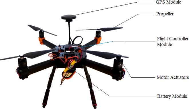
Figure 10.

Quadrotor model representing the reference coordinates along with the forces and moments.
Case Study 2: Quadrotor Control Using LyNMPC and Proposed Controller: Simulation
Non-Linear Mathematical Model of the Quadrotor
The system mathematical model is developed by analyzing the dynamic equations of a quadrotor system, under increasingly provisional simulation assumptions:
-
1.
The inertial characteristics of the system change with time, and
-
2.
The quadrotor fuselage is symmetrical and rigid, and the rotating bodies are the thin circular plates.
Based on the formulations of Newton and Euler, the equations of the quadrotor have been developed with the help of the above assumptions. These models can be used to derive the state space model of the quadrotor MAV, which, in turn, will be implemented in the consequent design of the controller for the system.
Kinematic Model
The initial step in deriving the quadrotor kinematic and dynamic equations is to fix the reference frames for the linear and angular measurements, which are the North–East–Down coordinate reference and the standard body-fixed coordinate reference.
The direction cosine matrix R facilitates the conversion of coordinates from the body frame to the inertial coordinate frame which provides for the attitude of the MAV. The attitude of the MAV is represented by the Euler angles (ϕ; θ; and ψ) denoting the rotational motion about the linear coordinate axes. The matrix R is obtained by considering a set of principle rotational motions, as given below.
 |
22 |
The control vector, U, is obtained from the quadrotor forces and moments, given by
| 23 |
where
| 24 |
| 25 |
| 26 |
| 27 |
Representing the control inputs in a matrix form
 |
28 |
U1, U2, U3, and U4 is the resultant control inputs from the four propellers that account for the altitude and attitude variations of the quadrotor and its time derivatives. The control vector (U), thus, decouples the rotational subsystem from the translational subsystem, resulting in the individual control of the attitude and altitude of the quadrotor system through the respective control inputs.
Using the equations of angular rotational acceleration, equations, and those of translational equations, the complete quadrotor mathematical model, can be written as follows in a representation of state space
 |
29 |
where
 |
30 |
The above matrix equation represents the generalized quadrotor non-linear state space representation. The system constants are given below which has been obtained from physical measurements and later verified using the particle swarm optimization method (Table 3).
Table 3. Parameters of HEXSOON Edu 450 Quadrotor.
| symbol | parameters | value | unit |
|---|---|---|---|
| m | mass | 1.516 | kg |
| l | length of the arm | 0.225 | m |
| Ixx | moment of inertia about x axis | 0.0060427 | kg m2 |
| Iyy | moment of inertia about y axis | 0.0070262 | kg m2 |
| Izz | moment of inertia about z axis | 0.00023 | kg m2 |
| Jr | rotor moment of inertia | 0.007559 | kg m2 |
| CD | coefficient of drag | 0.01328 | |
| CT | coefficient of thrust | 0.1939 | |
| g | acceleration due to gravity | 9.81 | m s–2 |
Control Formulation
This section of the report is a case study based on the reference, where an NMPC control algorithm has been employed for the trajectory tracking and control of a batch reactor.33 A similar inspired NMPC algorithm has been employed to achieve the results obtained in this case study.
The objective function used in the LyNMPC strategy is defined as:
| 31 |
where
| 32 |
| 33 |
| 34 |
| 35 |
where n = 6 is the number of output variables and qx and qU are weighting functions. The values of qx and qU are selected such that they are positive definite. The values of qx and qU as per the simulations, are given below
 |
36 |
 |
37 |
In the cost function JNMPC, the first term, V includes component that reduces the cross interference that is induced due to the fact that the intense oscillating or pulsating behavior of the inputs. This can cause damages to the hardware in real-time fast operating applications. The objective function is said to be under the influence of the following input constraints
| 38 |
The objective function is a function of the output variables (x, y, z, ϕ, θ, and ψ) and the control inputs (U1, U2, U3, and U4). The prediction horizon used is 120 time units and control horizon is 20 time units.
Calculation of the Hard Input Constraints
The input constraints are calculated based on the maximum and minimum force and moments that can be produced by the quadrotor motors in conjunction with the propellers. The calculation of each input constraint is given below
Altitude control constraint (U1,max and U1,min)
The maximum thrust from one of the motor in terms of mass, Fi = 12.684 N or 1.293 kg
The maximum total thrust produced
 |
39 |
The minimum thrust produced, U1,min = 0 N, because the motors can be powered down, thus producing 0 thrust.
Roll control constraint (U2,max and U2,min)
 |
40 |
Pitch control constraint (U3,max and U3,min)
The pitch control is attained similar to roll control, hence the value of
| 41 |
Yaw control constraint (U4,max and U4,min)
The yaw control of the quadrotor is obtained with all the motor working to produce differential torque. This can be mathematically represented as follows
| 42 |
Hence, the hard input constraints on the cost function,JNMPC, presented as per eq 38 are as follows
| 43 |
| 44 |
| 45 |
| 46 |
Results
The results obtained for the non-linear model of the quadrotor system controlled using the LyNMPC algorithm have been illustrated in Figures 11–21 below. Figure 11 represents the three-dimensional response plot for the quadrotor system along with the reference trajectory. The three-dimensional plot of the LyNMPC algorithm shows the use of an ascending spiral trajectory as reference trajectory with the system output tracking the reference in closed proximity.
Figure 11.

Three-dimensional response plot for the LyNMPC controlled Quadrotor system.
Figure 21.

Controller U4 response plot for the LyNMPC-controlled quadrotor system.
Figure 13.

Individual state variable response plot for the Y-coordinate using LyNMPC.
Figure 16.

Individual state variable response plot for the pitch angle using LyNMPC.
Figure 19.

Controller U2 response plot for the LyNMPC-controlled quadrotor system.
Figure 20.

Controller U3 response plot for the LyNMPC-controlled quadrotor system.
Figures 12–14 represent the respective X, Y, and Z position response of the quadrotor using the LyNMPC control along with the reference trajectories. The individual translational and rotational subsystem plots ensure the better understanding of the individual output variable response to the reference trajectory.
Figure 12.

Individual state variable response plot for the X-coordinate using LyNMPC.
Figure 14.

Individual state variable response plot for the Z-coordinate using LyNMPC.
Figures 15–17 represent the attitude response of the quadrotor using the LyNMPC algorithm.
Figure 15.

Individual state variable response plot for the roll angle using LyNMPC.
Figure 17.

Individual state variable response plot for the yaw angle using LyNMPC.
Figures 18–21 represent the control efforts produced by the LyNMPC algorithm to maintain trajectory tracking and control of the quadrotor.
Figure 18.

Controller U1 response plot for the LyNMPC-controlled quadrotor system.
The control efforts for the individual output variable are significantly low for the reference trajectory provided to the system. This is evident in the control effort plots shown above. The initial large variation in the control effort signifies the initial threshold at which the drone takes off from the ground. This threshold is as a result of the mass and its associated inertia in the system.
Proposed Control Algorithm: LyNMPC-Based Nonlinear Three-Mode (PID) Controller
The proposed controller is based on the computed gain values of the Lyapunov-based nonlinear control algorithm described in the previous section. The control inputs (gain values) are conditioned to derive the control law for a nonlinear PID controller. The control law is derived as given below.
Position Control
The position control of the quadrotor is derived based on the position error, that is, difference in the actual output of the system with the desired reference value. The position control is attained by the controller indirect method through attaining control over the angular positions ϕ and θ, that is, through U2 and U3.
| 47 |
| 48 |
where x1 and x3 are the state variables representing ϕ and θ, respectively.
| 49 |
| 50 |
Attitude Control
The rotational control of the quadrotor system is attained through the directional control by differential thrust from the rotors due their relative angular velocity. The final control law that affects the system is the sum of the proportional, differential, and integral control inputs. The initial iteration of the control input produced by the algorithm is given below
| 51 |
where
| 52 |
| 53 |
| 54 |
| 55 |
| 56 |
| 57 |
| 58 |
 |
59 |
Similar to the control law mentioned in case study 1 for the proposed NPID for the batch reactor system, the control structure has a proportional, differential, and integral parts. Here, the terms βP, βI, and βD represent the proportional, differential, and integral errors in the system based on which the control signals are generated. The tuning parameters used for the control algorithm are given below in Table 4.
Table 4. Tuning Parameters of the Proposed Algorithm for the Bench-Scale Batch Reactor.
| tuning parameters of | i = 1 | i = 2 | i = 3 | i = 4 | ||||
|---|---|---|---|---|---|---|---|---|
| Roll Control | ||||||||
| proportional (cP,i) | ||||||||
| differential (cD,i) | b2a4 | –a3/b1 | a2 | |||||
| integral (cI,i) | ||||||||
| Pitch Control | ||||||||
| proportional (cP,i) | a2 | –a3 | ||||||
| differential (cD,i) | b2a4 | a1 | ||||||
| integral (cI,i) | a1a2 | b1 | a4b2 | a1 | ||||
| Yaw Control | ||||||||
| proportional (cP,i) | ||||||||
| differential (cD,i) | a4b2 | |||||||
| integral (cI,i) | ||||||||
| X-axis Translational Control | ||||||||
| proportional (cP,i) | a4 | a2b2 | ||||||
| differential (cD,i) | a1 | |||||||
| integral (cI,i) | a4 | |||||||
| Y-axis Translational Control | ||||||||
| proportional (cP,i) | a2a4b1 | |||||||
| differential (cD,i) | a2b2 | a4b2 | ||||||
| integral (cI,i) | ||||||||
| Z-axis Translational Control | ||||||||
| proportional (cP,i) | a4 | |||||||
| differential (cD,i) | a1 | a42 | ||||||
| integral (cI,i) | a44 | |||||||
The calculation of the terms a1 to a5 and b1 to b3 are given in eq 30, which are functions of the moment of inertia of the quadrotor.
Results
The simulation results obtained for the quadrotor system controlled using the NPID algorithm is illustrated below. Figure 22 represents the three-dimensional response plot for the quadrotor system along with the reference trajectory. The performance of the proposed control for the quadrotor is not properly optimized. This can be achieved for the same using an appropriate optimization algorithm and fine tuning the control system.
Figure 22.

Three-dimensional response plot for the LyNMPC-based NPID-controlled Quadrotor system.
Figures 23–25 represent the respective X, Y, and Z position response of the quadrotor along with the reference trajectory.
Figure 23.

Individual state variable response plot for X-coordinate for the LyNMPC-based NPID-controlled Quadrotor system.
Figure 25.

Individual state variable response plot for Z-coordinate for the LyNMPC-based NPID-controlled quadrotor system.
Figure 24.

Individual state variable response plot for Y-coordinate for the LyNMPC-based NPID-controlled quadrotor system.
Conclusions
In this research article, the proposed NPID controller based on the LyNMPC algorithm is simulated for the highly nonlinear models of batch reactor and quadrotor systems and also validated the LyNMPC algorithm on the batch reactor polymerization process. The nonlinear dynamic equations of the quadrotor and batch reactor systems have been presented under case studies 1 and 2. The detailed results and its discussion are shown in case studies 1 and 2. From the simulation results, it can be concluded that LyNMPC-based NPID algorithms promise to be better at handling constraints in the system dynamics via the smooth manipulated variables. This can be seen in terms of the trajectory tracking with respect to the temperature profile in the batch reactor as well as the trajectory tracking with respect to the reference flight trajectory in quadrotor. The control efforts of NPID is minimal, that is, the magnitude of the control signal is well within 20%, and on other hand, the linear PID control results with ON/OFF kind for a highly nonlinear process. The initial observation of the proposed NPID algorithm stabilizes the nonlinear system, and by fine-tuning the tuning parameters, tight tracking of the trajectory with minimum error is possible.
Future Work
The future work for this research includes the experimental validation of the NPID control algorithm on the bench-scale setup for the acrylamide polymerization in batch reactor and quadrotor trajectory tracking with manual control input via radio transmitter using Pixhawk 2.1. Both the mentioned works are under progress. Comparison of the performance of the proposed controller with other benchmark control scales can establish its validity.
Acknowledgments
The authors would like to express gratitude to the funding agencies: (1) Manipal Academy of Higher Education (MAHE) for the seed money grant toward the batch reactor experimental setup under grant ID: 00000220 dated 1/1/2020. (2) Indian Space Research Organization/Department of Space Respond Program, Government of India, has funded this project under the project code: ISRO/RES/3/822/19-20, dated on August 8th, 2019. (3) Karnataka State Council of Science and Technology sponsored toward proximity sensors and camera modules under: 45S_MTECH_024, dated: 11th May, 2022. The authors would intimate their gratitude toward Prof. Prashant Mhaskar, McMaster University, Canada and P.S.J. Prakash, Dean, MIT, Anna University, for giving us meaningful insights into batch reactor and its experimental validation.
The authors declare no competing financial interest.
References
- Shettigar J P.; Lochan K.; Jeppu G.; Palanki S.; Indiran T. Development and Validation of Advanced Nonlinear Predictive Control Algorithms for Trajectory Tracking in Batch Polymerization. ACS Omega 2021, 6, 22857–22865. 10.1021/acsomega.1c03386. [DOI] [PMC free article] [PubMed] [Google Scholar]
- Shettigar J P.; Kumbhare J.; Yadav E. S.; Indiran T. Wiener Neural Network-Based Modeling and Validation of Generalized Predictive Control on a Laboratory-Scale Batch Reactor. ACS Omega 2022, 7, 16341–16351. 10.1021/acsomega.1c07149. [DOI] [PMC free article] [PubMed] [Google Scholar]
- Yadav E. S.; Shettigar J P.; Poojary S.; Chokkadi S.; Jeppu G.; Indiran T. Data-Driven Modeling of a Pilot Plant Batch Reactor and Validation of a Nonlinear Model Predictive Controller for Dynamic Temperature Profile Tracking. ACS Omega 2021, 6, 16714–16721. 10.1021/acsomega.1c00087. [DOI] [PMC free article] [PubMed] [Google Scholar]
- Yadav E. S.; Indiran T.; Priya S. S. Optimal Energy Consumption of the Distillation Process and Its Product Purity Analysis Using Ultraviolet Spectroscopy. ACS Omega 2021, 6, 1697–1708. 10.1021/acsomega.0c05731. [DOI] [PMC free article] [PubMed] [Google Scholar]
- Yadav E. S.; Indiran T.; Priya S. S.; Fedele G. Parameter Estimation and an Extended Predictive-Based Tuning Method for a Lab-Scale Distillation Column. ACS Omega 2019, 4, 21230–21241. 10.1021/acsomega.9b02713. [DOI] [PMC free article] [PubMed] [Google Scholar]
- Kapnopoulos A.; Alexandridis A. A cooperative particle swarm optimization approach for tuning an MPC-based quadrotor trajectory tracking scheme. Aero. Sci. Technol. 2022, 127, 107725. 10.1016/j.ast.2022.107725. [DOI] [Google Scholar]
- Sun S.; Romero A.; Foehn P.; Kaufmann E.; Scaramuzza D. A Comparative Study of Nonlinear MPC and Differential-Flatness-Based Control for Quadrotor Agile Flight. IEEE Trans. Robot. 2022, 1–17. 10.1109/tro.2022.3177279. [DOI] [Google Scholar]
- Carlos B. B.; Sartor T.; Zanelli A.; Frison G.; Burgard W.; Diehl M.; Oriolo G.. International Conference on Sustainable Computing and Data Communication Systems (ICSCDS); IEEE, 2022.
- Torrente G.; Kaufmann E.; Fohn P.; Scaramuzza D. Data-Driven MPC for Quadrotors. IEEE Rob. Autom. Lett. 2021, 6, 3769–3776. 10.1109/lra.2021.3061307. [DOI] [Google Scholar]
- Wang D.; Pan Q.; Shi Y.; Hu J.; Zhao C. Efficient Nonlinear Model Predictive Control for Quadrotor Trajectory Tracking: Algorithms and Experiment. IEEE Trans. Cybern. 2021, 51, 5057–5068. 10.1109/tcyb.2020.3043361. [DOI] [PubMed] [Google Scholar]
- Xi L.; Wang X.; Jiao L.; Lai S.; Peng Z.; Chen B. M. GTO-MPC-Based Target Chasing Using a Quadrotor in Cluttered Environments. IEEE Trans. Ind. Electron. 2022, 69, 6026–6035. 10.1109/tie.2021.3090700. [DOI] [Google Scholar]
- Hanover D.; Foehn P.; Sun S.; Kaufmann E.; Scaramuzza D. Performance, Precision, and Payloads: Adaptive Nonlinear MPC for Quadrotors. IEEE Rob. Autom. Lett. 2022, 7, 690–697. 10.1109/lra.2021.3131690. [DOI] [Google Scholar]
- Zhang K.; Shi Y.; Sheng H. Robust Nonlinear Model Predictive Control Based Visual Servoing of Quadrotor UAVs. IEEE ASME Trans. Mechatron. 2021, 26, 700–708. 10.1109/tmech.2021.3053267. [DOI] [Google Scholar]
- Greatwood C.; Richards A. G. Reinforcement learning and model predictive control for robust embedded quadrotor guidance and control. Aut. Robots 2019, 43, 1681–1693. 10.1007/s10514-019-09829-4. [DOI] [Google Scholar]
- Eskandarpour A.; Sharf I. A constrained error-based MPC for path following of quadrotor with stability analysis. Nonlinear Dynam. 2020, 99, 899–918. 10.1007/s11071-019-04859-0. [DOI] [Google Scholar]
- Islam M.; Okasha M.; Sulaeman E. A Model Predictive Control (MPC) Approach on Unit Quaternion Orientation Based Quadrotor for Trajectory Tracking. Int. J. Control Autom. Syst. 2019, 17, 2819–2832. 10.1007/s12555-018-0860-9. [DOI] [Google Scholar]
- Owis M.; El-Bouhy S.; El-Badawy A.. Quadrotor Trajectory Tracking Control using Non-Linear Model Predictive Control with ROS Implementation, 2019; pp 243–247.
- L’Afflitto A.; Anderson R. B.; Mohammadi K. An Introduction to Nonlinear Robust Control for Unmanned Quadrotor Aircraft: How to Design Control Algorithms for Quadrotors Using Sliding Mode Control and Adaptive Control Techniques [Focus on Education]. IEEE Control Syst. Mag. 2018, 38, 102–121. 10.1109/mcs.2018.2810559. [DOI] [Google Scholar]
- Zou Y. Nonlinear robust adaptive hierarchical sliding mode control approach for quadrotors. Int. J. Robust Nonlinear Control 2017, 27, 925–941. 10.1002/rnc.3607. [DOI] [Google Scholar]
- Chingozha T.; Nyandoro O.. Adaptive Sliding Backstepping Control of Quadrotor UAV Attitude. IFAC Proceedings Volumes, 2014; Vol. 47, pp 11043–11048. 19th IFAC World Congress.
- Ahmed N.; Chen M. Sliding mode control for quadrotor with disturbance observer. Adv. Mech. Eng. 2018, 10, 168781401878233. 10.1177/1687814018782330. [DOI] [Google Scholar]
- Voos H.Nonlinear Control of a Quadrotor Micro-UAV Using Feedback-Linearization, 2009; Vol. 1–6.
- Nadda S.; Swarup A. On adaptive sliding mode control for improved quadrotor tracking. J. Vib. Control 2018, 24, 3219–3230. 10.1177/1077546317703541. [DOI] [Google Scholar]
- Salichon M.; Tumer K. Evolving a Multiagent Controller for Micro Aerial Vehicles. IEEE Trans. Syst. Man Cybern. C Appl. Rev. 2012, 42, 1772–1783. 10.1109/tsmcc.2012.2221696. [DOI] [Google Scholar]
- Razmi H.; Afshinfar S. Neural network-based adaptive sliding mode control design for position and attitude control of a quadrotor UAV. Aero. Sci. Technol. 2019, 91, 12–27. 10.1016/j.ast.2019.04.055. [DOI] [Google Scholar]
- Mofid O.; Mobayen S. Adaptive sliding mode control for finite-time stability of quad-rotor UAVs with parametric uncertainties. ISA Trans. 2018, 72, 1–14. 10.1016/j.isatra.2017.11.010. [DOI] [PubMed] [Google Scholar]
- Abdolhosseini M. An Efficient Model Predictive Control Scheme for an Unmanned Quadrotor Helicopter. J. Intell. Rob. Syst. 2013, 70, 27–38. 10.1007/s10846-012-9724-3. [DOI] [Google Scholar]
- Çakıcı F.; Leblebicioğlu M. K. Design and analysis of a mode-switching micro unmanned aerial vehicle. Int. J. Micro Air Veh. 2016, 8, 221–229. 10.1177/1756829316678876. [DOI] [Google Scholar]
- Bhattacharjee D.; Subbarao K.. Robust Control Strategy for Quadcopters using Sliding Mode Control and Model Predictive Control, 2020.
- Cao G.; Lai E. M.-K.; Alam F.. Gaussian Process Model Predictive Control of Unmanned Quadrotors, 2016; pp 200–206.
- Raffo G. V.; Ortega M. G.; Rubio F. R.. MPC with Nonlinear H-Infinity Control for Path Tracking of a Quad-Rotor Helicopter, 2008.
- Yang Y.; Yan Y. Attitude regulation for unmanned quadrotors using adaptive fuzzy gain-scheduling sliding mode control. Aero. Sci. Technol. 2016, 54, 208–217. 10.1016/j.ast.2016.04.005. [DOI] [Google Scholar]
- Mahmood M.; Mhaskar P. Lyapunov-based model predictive control of stochastic nonlinear systems. Automatica 2012, 48, 2271–2276. 10.1016/j.automatica.2012.06.033. [DOI] [Google Scholar]